模具设计类论文翻译(原文和译文)
- 格式:doc
- 大小:253.50 KB
- 文档页数:15

Injection MoldingThe basic concept of injection molding revolves around the ability of a thermoplastic material to be softened by heat and to harden when cooled .In most operations ,granular material (the plastic resin) is fed into one end of the cylinder (usually through a feeding device known as a hopper ),heated, and softened(plasticized or plasticized),forced out the other end of the cylinder, while it is still in the form of a melt, through a nozzle into a relatively cool mold held closed under pressure.Here,the melt cools and hardens until fully set-up. The mold is then opened, the piece ejected, and the sequence repeated.Thus, the significant elements of an injection molding machine become: 1) the way in which the melt is plasticized (softened) and forced into the mold (called the injection unit);2) the system for opening the mold and closing it under pressure (called the clamping unit);3) the type of mold used;4) the machine controls.The part of an injection-molding machine, which converts a plastic material from a sold phase to homogeneous seni-liguid phase by raising its temperature .This unit maintains the material at a present temperature and force it through the injection unit nozzle into a mold .The plunger is a combination of the injection and plasticizing device in which a heating chamber is mounted between the plunger and mold. This chamber heats the plastic material by conduction .The plunger, on each stroke; pushes unbelted plastic material into the chamber, which in turn forces plastic melt at the front of the chamber out through the nozzleThe part of an injection molding machine in which the mold is mounted, and which provides the motion and force to open and close the mold and to hold the mold close with force during injection .This unit can also provide other features necessary for the effective functioning of the molding operation .Movingplate is the member of the clamping unit, which is moved toward a stationary member. the moving section of the mold is bolted to this moving plate .This member usually includes the ejector holes and mold mounting pattern of blot holes or “T” slots .Stationary plate is the fixed member of the clamping unit on which the stationary section of the mold is bolted .This member usually includes a mold-mounting pattern of boles or “T” slots. Tie rods are member of the clamping force actuating mechanism that serve as the tension member of the clamp when it is holding the mold closed. They also serve as a gutted member for the movable plate .Ejector is a provision in the clamping unit that actuates a mechanism within the mold to eject the molded part(s) from the mold .The ejection actuating force may be applied hydraulically or pneumatically by a cylinder(s) attached to the moving plate, or mechanically by the opening stroke of the moving plate.Methods of melting and injecting the plastic differ from one machine to another and are constantly being implored .conventional machines use a cylinder and piston to do both jobs .This method simplifies machine construction but makes control of injection temperatures and pressures an inherently difficult problem .Other machines use a plasticizing extruder to melt the plastic and piston to inject it while some hare been designed to use a screw for both jobs :Nowadays, sixty percent of the machines use a reciprocating screw,35% a plunger (concentrated in the smaller machine size),and 5%a screw pot.Many of the problems connected with in ejection molding arise because the densities of polymers change so markedly with temperature and pressure. thigh temperatures, the density of a polymer is considerably cower than at room temperature, provided the pressure is the same.Therefore,if molds were filled at atmospheric pressure, “shrinkage” would make the molding deviate form the shape of the mold.To compensate for this poor effect, molds are filled at high pressure. The pressure compresses the polymer and allows more materials to flow into the mold, shrinkage is reduced and better quality moldings are produced.Cludes a mold-mounting pattern of bolt holes or “T” slots. Tie rods are members of the clamping force actuating mechanism that serve as the tension members of clamp when it is holding the mold closed. Ejector is a provision in the calming unit that actuates a mechanism within the mold to eject the molded part(s) form the mold. The ejection actuating force may be applied hydraulically or pneumatically by a cylinder(s) attached to the moving plate, or mechanically by the opening stroke of the moving plate.The function of a mold is twofold: imparting the desired shape to the plasticized polymer and cooling the injection molded part. It is basically made up of two sets of components: the cavities and cores and the base in which the cavities and cores are mounted. The mold ,which contains one or more cavities, consists of two basic parts :(1) a stationary molds half one the side where the plastic is injected,(2)Moving half on the closing or ejector side of the machine. The separation between the two mold halves is called the parting line. In some cases the cavity is partly in the stationary and partly in the moving section. The size and weight of the molded parts limit the number of cavities in the mold and also determine the machinery capacity required. The mold components and their functions are as following:(1)Mold Base-Hold cavity (cavities) in fixed, correctposition relative to machine nozzle.(2)Guide Pins-Maintain Proper alignment of entry into moldinterior.(3)Spree Bushing (spree)-Provide means of entry into moldinterior.(4)Runners-Conroy molten plastic from spree to cavities.(5)Gates-Control flow into cavities.(6)Cavity (female) and Force (male)-Control the size,shape and surface of mold article.(7)Water Channels-Control the temperature of mold surfacesto chill plastic to rigid state.(8)Side (actuated by came, gears or hydrauliccylinders)-Form side holes, slots, undercuts and threaded sections.(9)Vent-Allow the escape of trapped air and gas.(10)Ejector Mechanism (pins, blades, stripper plate)-Ejectrigid molded article form cavity or force.(11)Ejector Return Pins-Return ejector pins to retractedposition as mold closes for next cycle.The distance between the outer cavities and the primary spree must not be so long that the molten plastic loses too much heat in the runner to fill the outer cavities properly. The cavities should be so arranged around the primary spree that each receives its full and equal share of the total pressure available, through its own runner system (or the so-called balanced runner system).The requires the shortest possible distance between cavities and primary sprue, equal runner and gate dimension, and uniform culling.注射成型注射成型的基本概念是使热塑性材料在受热时熔融,冷却时硬化,在大部分加工中,粒状材料(即塑料树脂)从料筒的一端(通常通过一个叫做“料斗”的进料装置)送进,受热并熔融(即塑化或增塑),然后当材料还是溶体时,通过一个喷嘴从料筒的另一端挤到一个相对较冷的压和封闭的模子里。
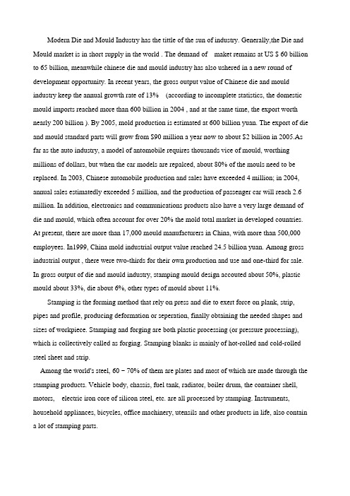
Modern Die and Mould Industry has the tittle of the sun of industry. Generally,the Die and Mould market is in short supply in the world . The demand of maket remains at US $ 60 billion to 65 billion, meanwhile chinese die and mould industry has also ushered in a new round of development opportunity. In recent years, the gross output value of Chinese die and mould industry keep the annual growth rate of 13% (according to incomplete statistics, the domestic mould imports reached more than 600 billion in 2004 , and at the same time, the export worth nearly 200 billion ). By 2005, mold production is estimated at 600 billion yuan. The export of die and mould standard parts will grow from $90 million a year now to about $2 billion in 2005.As far as the auto industry, a model of antomobile requires thousands vice of mould, worthing millions of dollars, but when the car models are repalced, about 80% of the mouls need to be replaced. In 2003, Chinese automobile production and sales have exceeded 4 million; in 2004, annual sales estimatedly exceeded 5 million, and the production of passenger car will reach 2.6 million. In addition, electronics and communications products also have a very large demand of die and mould, which often account for over 20% the mold total market in developed countries. At present, there are more than 17,000 mould manufacturers in China, with more than 500,000 employees. In1999, China mold industrial output value reached 24.5 billion yuan. Among gross industrial output , there were two-thirds for their own production and use and one-third for sale. In gross output of die and mould industry, stamping mould design accouted about 50%, plastic mould about 33%, die about 6%, other types of mould about 11%.Stamping is the forming method that rely on press and die to exert force on plank, strip, pipes and profile, producing deformation or seperation, finally obtaining the needed shapes and sizes of workpiece. Stamping and forging are both plastic processing (or pressure processing), which is collectively called as forging. Stamping blanks is mainly of hot-rolled and cold-rolled steel sheet and strip.Among the world's steel, 60 ~ 70% of them are plates and most of which are made through the stamping products. Vehicle body, chassis, fuel tank, radiator, boiler drum, the container shell, motors, electric iron core of silicon steel, etc. are all processed by stamping. Instruments, household appliances, bicycles, office machinery, utensils and other products in life, also contain a lot of stamping parts.Stampings are thin, uniform, light and strong compared with castings and forgings. Stamping can produce the workpiece with reinforced rib, ups and downs, and flange to improve its rigidity, which is difficult to manufacture by other method. As a result of precision molds, precision parts up to micron level, and high repetition accuracy, the same specifications, we can stamp out of a hole, boss and so on.Generally cold stamping parts do not need cutting, or only need a small amount of cutting. Hot stampi ng parts’s precision and surface state are below the cold stamping parts, but still better than the castings, forgings, because of its less cutting.Stamping is a highly efficient production methods, using compound die, especially themulti-task position progressive die, in a stamping press to complete the multi-channel processes, realizing the whole Automated production from the raw material coil, flattening, punching to forming, finishing. With high efficiency, good working conditions, low production costs, generally it can produce hundreds per minute.Stamping are mainly classified by process, which can be divided into separate processes and forming process two categories. Separation process, also known as punching, its purpose is to make the stamping parts separated from the sheet along the contour lines, while maintaining the quality requirements of separate section. Forming process is intended to provide blank sheet with plastic deformation without breaking, getting the required shape and size of the workpiece. In actual production, it is often a variety of processes to be applied to a workpiece. Punching, bending, shearing, deep drawing, bulging, spinning,and correction are the several major stamping process.Surface and the internal performance of sheet metal have a great influence on the quality of the stamping finished product, which require stamping material thickness precision, uniform; smooth surface, no spots, no scars, no scratches, no surface cracks; uniform yield strength, no obvious Direction; uniform extension rate; low yield ratio; low hardening.In actual production, we often use the technology test similar to stamping process, such as deep drawing performance test, bulging performance test and so on to ensure product quality and a high pass rate.The accuracy and structure of mold directly affect the forming and precision of stamping parts. The manufacturing costs and life of mold is an important factor in cost and quality of stamping.The design and manufacturing of mold need more time, which extende the production preparation time of a new stamping.Standardization of the die holder, mold bases and guide and development of simple pieces of the mold (for small batch production), compound die, multi-task position progressive die (for mass production), and the development of quick die change equipment, can reduce the workload for stamping and shorten the preparation time, and can apply to reduce the workload and preparing time of the stamping production to, making mass production of advanced punching technology reasonably applied to many varieties of small batch production.In addition to the thick plate , water stamping press is used for forming. But in general, mechanical presses are used. Modern high-speed multi-tasking mechanical press as the center position, configuration of open book, flattening, collection of thefinished , transportation and other machinery and tooling libraries and quick die change equipment, and using the computer program to control, can be composed of high-productivity automatic punch line.Under the condition that producing tens, hundreds of cases of stampings per minute, and completing feeding, stamping, out parts, waste discharge processes, etc. in a short period of time, the acciden of physical, equipment and quality are often occurring. Therefore, safety of the stamping is a very important issue.The development of die technology should adapt to mold products’ reqirements "short delivery time", "high precision", "good quality", and "low price ". To meet this requirement, it is urgent need to develop the following items:(1) Comprehensively promote cad / cam / cae technical. mold cad / cam / cae technology is the direction of development of mold design and manufacturing. With the development and progress of computer software, it is ripe to universal cad / cam / cae technology , and the businesses will increase cad / cam technology training and technical service efforts; further expand the scope of cae technology. The development of computers and networks are making cad / cam / cae technology trans-regional, cross-enterprise, campus-wide in the whole industry as possible to promote and achieve re-integration of technical resources to enable virtual manufacturing possible.(2) High-speed milling process. In recent years, the development of foreign high-speed milling process, significantly improve the processing efficiency and to get a high surface finish. In , itcan also processe the module with high hardness, but also have the features of low temperature rise, thermal deformation and so on. The development of high-speed milling technology injected new vitality for automotive, home appliance manufacturing industry in the large cavity mold. It currently moves for a more agile, intelligent, integrated direction.(3)Die scanning and digitizing system.High-speed scanner and mold scanning system provides scan rom a model or physical model to processing required number of functions,greatly reducing the manufacturing cycle in the development of mold. Some quick scan system can be quickly installed in existing CNC milling machine and machining center, for fast data acquisition, automatic generation of a variety of CNC machining process, different formats cad data for, "Reverse Engineering”of mold manufacturing . Die scanning system has been successfully applied in the automotive, motorcycle, household appliances and other industries, I believe it will play a greater role during the in the "Tenth Five".(4) ED Milling. ED Milling Technology, also known as invasive as processing technology, which is an alternative to the traditional processing of the cavity by forming a new electrode technology, it is a simple high-speed rotation of the tubular electrode as Three-dimensional or two-dimensional contour machining (CNC milling, as the same), so no longer need to create a complex shape electrode, which is obviously a major field of EDM development. This technique has been used abroad in the mold processing machine application. Expected that this technology will be developed.(5) Increasing the degree of standardization of the mold die. It is estimated using the present standard mold coverage reaching about 30%. Developed countries is generally about 80%.(6) High-quality materials and advanced surface treatment technology and application of high quality steel, the corresponding surface treatment technology to improve the life of the mold it is very necessary. Mold heat treatment and surface treatment can fully mold steel material properties play a key part. Direction of development of mold heat treatment is the use of vacuum heat treatment. In addition to the mold surface treatment of advanced technology should be developed to improve vapor deposition (tin, tic, etc.), plasma spraying technology.(7) Die polishing automation, intelligent mold surface quality of mold life, the appearance of quality parts and so have a greater impact of automation and intelligence of the grinding and polishing methods replace the existing manual operation to Improve the quality of the moldsurface is an important trend.8) The development of mold automatic processing system is our long-term development goals. Automatic mold machine processing system should be more reasonable with more than one machine.Resistance one: low mechanization and automation. In U.S., 70% of 680 punch line have multi-task presses, and in Japan, 32% of 250 production lines are multi-tasking digital presses, and this large-scale international level on behalf of today's multi-mission presses in our application is one of the few; SME equipment is generally more backward, high-energy supplies, seriously environmental pollution; head forming poorly equipped, manual operation than the major; fine blanking machine is expensive, 5 to 10 times of the general press; most companies who are unable tor invest hinde fine blanking technology application in China; hydroforming, IUH in particular, need large equipment investment, so it is hard to start domesticly.Breakthrough: accelerating transformation.To change the current backward situation of most manual loading and unloading, combined with the specific circumstances, adopt new technology, improved mechanization and automation. Auto body panel stamping should be single-line automation, robotics punch line, especially for large multi-mission presses direction. Increasing investment to accelerate the technological transformation of stamping production line, reach to the current international standards as soon as possible. With microelectronics technology and communication technology, automation and flexibility of sheet metal forming equipment have technology base. Should accelerate the development of digital element of the flexible forming, hydroforming technology, high precision composite forming technology to adapt to the profile bending technology and related equipment for lightweight body structure of a new generation. While transform the domestic old equipment to play the new production capacity.Resistance two: the production of low concentration.Many large Automotive Group form a closed internal support, leading to many kinds of stamping parts of enterprises, low concentration of the production., small scale, easy to create low-level redundant construction, difficult to meet the specialized division of labor production, and weak market competition; Motor Car stamping industry is facing fierce market competition, in the " Optimal and be very bad, but not tide "status; head manufacturing enterprises are smalland dispersed, only 39.2% concentration.Breakthroughs: take the professional road.Quickly change the current "large","scattered and poor " pattern, as soon as possible separate stamping parts from the vehicle group , to establish several large-scale supplier of stamping parts manufacturing and dozens of small and specialized parts and components factories.according to the large, medium and small category of stamping parts. Through the professional road, the producing of stamping parts and components can be bigger and stronger and we can become internationally competitive supplier of stamping parts.Resistance three: self-sufficiency rate of sheet stamping and different specifications are not enough.At present, China can only meet 60% of car sheet metal, while the high-end cars with steel, such as high strength plate, zinc alloy plate, wide boards (1650mm above) are all imported.Breakthrough: the materials used should be coordinated with the development of the industry.Variety of automotive steel sheets tend to be more reasonable toward the high-strength, high corrosion resistance and a variety of thin steel plate direction, and to improve the stamping performance. Aluminum, magnesium alloy has become a vehicle rational lightweight materials, and expanding the application is imperative.Resistance four: transformtion of scientific and technological achievements into advanced technology and the promote are slow.In China, many new technology of start-stamping is not late, and some have reached the international advanced level, but they are often difficult to form the productive forces. Application of advanced stamping process is few, some only at the trial stage, with a slow absorption, transformation and promoting. Less investment cost of technology development leads to the slow mastery and application of advanced technology for enterprise, and insufficient capacity to develop and innovate. At present, most domestic enterprises are still using the traditional stamping technology, with the lack of research and technology reserves for forming technology of the next generation of lightweight vehicle structures and materials.Breaking point: the way United with the industry, academia and research.Compared to Europe, the United States and Japan, our largest gap is lack of a consortium of industry, academia and research.Research is difficult to expand,and the results can not be transformed into productivity as soon as possible. It should focus on large-scale development and industrialization projects, supported by to universities and research institutes for technology, by the base of business for the application,to form of corporate joint entity united byproducts, equipment, materials, and technology, to form the benign cycle of both development and innovation, but also the rapid industrialization.Resistance five:a large, fine imported mold.Currently, the stamping die materials, design, production can not meet all the needs of the domestic automobile development, and standardization is still low, about 40% to 45%, while the international community in general about 70%.Breakthrough: to enhance information technology, standardization.Transformation of information technology must use die enterprises , focusing promotment of CAD / CAM / CAE integration technology, especially computer simulation analysis and optimization technology (CAE)of forming process. Accelerate the process of the mold standardization to improve the accuracy and exchange rates. Strive for the coverage of using standard mold in 2005 up to 60%, in 2010 more than 70% to meet market demand basically.Resistance six: lack of professionals.Among industry, high-quality professionals with a mastery of advanced design analysis and digital technology can not meet needs of rapid development of the pressing industry. Especially in the motorcycle industry, the persons with stamping techniques, skills and knowledge are in terrible short and a large number outflow. In addition, project design, design rights and voting rights of many foreign joint venture company are mastered by the foreign side, but it is difficult for our stamping technical staff really grasp the true meaning of stamping process. Breakthrough: to improve the quality of industry personnel.This is an urgent task, but also a long-term and systematic task. The revitalization of Chinse press industry needs a large number of high-level scientific and technological personnel, a large number of entrepreneurs who are familiar with domestic and foreign markets and have modern management knowledge and skills , a large number of senior skilled personnel with sophisticated technologies and processes. Must be willing to make great efforts, and plans to train at differentlevels.。

英文原文A CAD/CAE-integrated injection mold design system for plastic products Abstract Mold design is a knowledge-intensive process. This paper describes a knowledge-based oriented, parametric, modular and feature-based integrated computer-aided design/computer-aided engineering (CAD/CAE) system for mold design. Development of CAx systems for numerical simulation of plastic injection molding and mold design has opened new possibilities of product analysis during the mold design. The proposed system integrates Pro/ENGINEER system with the specially developed module for the calculation of injection molding parameters, mold design, and selection of mold elements. The system interface uses parametric and CAD/CAE feature-based database to streamline the process of design, editing, and reviewing. Also presented are general structure and part of output results from the proposed CAD/ CAE-integrated injection mold design system.Keywords Mold design . Numerical simulation . CAD . CAE1 IntroductionInjection molding process is the most common molding process for making plastic parts. Generally, plastic injection molding design includes plastic product design, mold design, and injection molding process design, all of which contribute to the quality of the molded product as well as production efficiency [1]. This is process involving many design parameters that need to be considered in a concurrent manner. Mold design for plastic injection molding aided by computers has been focused by a number of authors worldwide for a long period. Various authors have developed program systems which help engineers to design part, mold, and selection parameters of injection molding. During the last decade, many authors have developed computer-aided design/computer-aided engineering (CAD/CAE) mold design systems for plastic injection molding. Jong et al. [2] developed a collaborative integrated design system for concurrent mold design within the CAD mold base on the web, using Pro/E. Low et al. [3] developed an application for standardization of initial design of plastic injection molds. The system enables choice and management of mold base of standard mold plates, but does not provide mold and injection molding calculations. The authors proposed a methodology of standardizing the cavity layout design system for plastic injection mold such that only standard cavity layouts are used. When standard layouts are used, their layout configurations can be easily stored in a database. Lin at al. [4, 5] describe a structural design system for 3D drawing mold based on functional features using a minimum set of initial information. In addition, it is also applicable to assign the functional features flexibly before accomplishing the design of a solid model for the main parts of a drawing mold. This design system includes modules for selection and calculation of mold components. It uses Pro/E modules Pro/Program and Pro/Toolkit, and consists of modules for mold selection, modification and design. Deng et al. [6, 7] analyzed development of the CAD/CAE integration. The authors also analyzed systems and problems of integration between CAD and CAE systems for numerical simulation of injection molding andmold design. Authors propose a feature ontology consisting of a number of CAD/CAE features. This feature represents not only the geometric information of plastic part, but also the design intent is oriented towards analysis. Part features contain the overall product information of a plastic part, wall features, development features (such as chamfer, ribs, boss, hole, etc.), treatment features which contain analysis-related design information and sub wall developed features. Wall and development features are so called ―component features‖. God ec et al. [8, 9] developed a CAE system for mold design and injection molding parameters calculations. The system is based on morphology matrix and decision diagrams. The system is used for thermal, rheological and mechanical calculation, and material base management,Fig. 1 General structure of integrated injection mold design system for plastic productsbut no integration with commercial CAx software is provided. Huang et al. [10] developed a mold-base design system for injection molding. The database they used was parametric and feature-based oriented. The system used Pro/E for modeling database components. Kong et al. [11]developed a parametric 3D plastic injection mold design system integrated with solid works. Other knowledge-based systems, such as IMOLD, ESMOLD, IKMOULD, and IKBMOULD, have been developed for injection mold design. IMOLD divides mold design into four major steps; parting surface design, impression design, runner system design, and mold-base design. The software uses a knowledge-based CAD system to provide an interactive environment, assist designers in the rapid completion of mold design, and promote the standardization of the mold design process. IKB-MOULD application consists of databases and knowledge bases for mold manufacturing. Lou et al. [12] developed an integrated knowledge-based system for mold base design. The system has module for impression calculation, dimension calculation, calculation of the number of mold plates and selection of injection machine. The system uses Pro/ Mold Base library. This paper describes KBS and key technologies, such as product modeling, the frame-rule method, CBS, and the neural networks. A multilayer neural network has been trained by back propagation BP. This neural network adopts length, width, height and the number of parts in the mold as input and nine parameters (length, width, and height of up and down set-in, mold bases side thickness, bottom thickness of the core, and cavity plates) as output. Mok et al. [13, 14] developed an intelligent collaborative KBS for injection molds. Mok at el. [15] has developed an effective reuse and retrieval system that can register modeled standard parts using a simple graphical user interface even though designers may not know the rules of registration for a database. The mold design system was developed using an Open API and commercial CAD/computer aided manufacturing (CAM)/CAE solution. The system was applied to standardize mold bases and mold parts in Hyundai Heavy Industry. This system adopted the method of design editing, which implements the master model using features. The developed system provides methods whereby designers can register the master model, which is defined as a function of 3D CAD, as standard parts and effectively reuse standard parts even though they do not recognize the rules of the database.Todic et al. [16] developed a software solution for automated process planning for manufacturing of plastic injection molds. This CAD/CAPP/CAM system does not provide CAE calculation of parameters of injection molding and mold design. Maican et al. [17] used CAE for mechanical, thermal, and rheological calculations. They analyzed physical, mechanical, and thermal properties of plastic materials. They defined the critical parameters of loaded part. Nardin et al. [18] tried to develop the system which would suit all the needs of the injection molding for selection of the part–mold–technology system. The simulation results consist of geometrical and manufacturing data. On the basis of the simulation results, part designers can optimize part geometry, while mold designers can optimize the running and the cooling system of the mold. The authors developed a program which helps the programmers of the injection molding machine to transfer simulation data directly to the machine. Zhou et al. [1] developed a virtual injection molding system based on numerical simulation. Ma et al. [19] developed standard component library for plastic injection mold design using an object-oriented approach. This is an objector iented, library model for defining mechanical components parametrically. They developed anobject-oriented mold component library model for incorporating different geometric topologies and non-geometric information. Over the years, many researchers have attempted to automate a wholeFig. 2 Structure of module for numerical simulation of injection molding processFig. 3 Forms to define the mold geometrymold design process using various knowledge-based engineering (KBE) approaches, such as rule-based reasoning (RBR), and case base (CBR) and parametric design template (PDT). Chan at al. [20] developed a 3D CAD knowledge-based assisted injection mold design system (IKB mold). In their research, design rules and expert knowledge of mold design were obtained from experienced mold designers and handbooks through various traditional knowledge acquisition processes. The traditional KBE approaches, such as RBR, CBR, and simple PDT have been successfully applied to mold cavity and runner layout design automation of the one product mold. Ye et al. [21] proposed a feature-based and object-oriented hierarchical representation and simplified symbolic geometry approach for automation mold assembly modeling. The previously mentioned analysis of various systems shows that authors used different ways to solve the problems of mold design by reducing it to mold configureator (selector). They used CAD/CAE integration for creating precision rules for mold-base selection. Many authors used CAE system for numerical simulation of injection molding to define parameters of injection molding. Several also developed original CAE modules for mold and injection molding process calculation. However, common to all previously mentioned systems is the lack of module for calculation of mold and injection molding parameters which would allow integration with the results of numerical simulation. This leads to conclusion that there is a need to create a software systemwhich integrates parameters of injection molding with the result obtained by numericalFig. 4 Forms to determine the distance between the cooling channels and mold cavityFig. 5 Mold-base selector formssimulation of injection molding, mold calculation, and selection. All this would be integrated into CAD/CAE-integrated injection mold design system for plastic products.2 Structure of integrated CAD/CAE systemAs is well known, various computational approaches for supporting mold design systems of various authors use design automation techniques such as KBE (RBR, CBR, PDT) or design optimisation techniques such as traditional (NLP,LP, BB, GBA, IR, HR) or meta heuristic search such as (TS, SA, GA) and other special techniques such as (SPA, AR, ED).The developed interactive software system makes possible to perform: 3D modeling of the parts, analysis of part design and simulation model design, numerical simulation of injection molding, and mold design with required calculations.The system consists of four basic modules:& Module for CAD modeling of the part& Module for numerical simulation of injection molding processFig. 6 Form for mechanical mold calculation& Module for calculation of parameters of injection molding and mold design calculation and selection& Module for mold modeling (core and cavity design and design all residual mold components) The general structure of integrated injection mold design system for plastic products is shown in Fig. 1.2.1 Module for CAD modeling of the part (module I)The module for CAD modeling of the part is the first module within the integrated CAD/CAE system. This module is used for generating CAD model of the plastic product and appropriate simulation model. The result of this module is solid model of plastic part with all necessary geometrical and precision specifications. Precision specifications are: project name, number, feature ID, feature name, position of base point, code number of simulation annealing, trade material name, material grade, part tolerance, machine specification (name, clamping force, maximal pressure, dimensions of work piece), and number of cavity. If geometrical and precision specification is specified (given) with product model, the same are used as input to the next module, while this module is used only to generate the simulation model.2.2 Module for numerical simulation of injection molding process (module II)Module II is used for numerical simulation of injection molding process. User implements an iterative simulation process for determining the mold ability parameters of injection molding and simulation model specification. The structure of this module is shown in Fig. 2.After a product model is imported and a polymer is selected from the plastic material database,user selects the best location for gating subsystem. The database contains rheological, thermal, andmechanical properties of plastic materials. User defines parameters of injection molding and picks the location for the gating subsystem. Further analyses are carried out: the plastic flow, fill time, injection pressure, pressure drop, flow front temperature, presence of weld line, presence of air traps, cooling quality, etc.The module offers four different types of mold flow analysis. Each analysis is aimed at solving specific problems:& Part analysis—This analysis is used to test a known gate location, material, and part geometry to verify that a part will have acceptable processing conditions.& Gate analysis—This analysis tests multiple gate locations and compares the analysis outputs to determine the optimal gate location.& Sink mark analysis—This analysis detects sink mark locations and depths to resolve cosmetic problems before the mold is built eliminating quality disputes that could arise between the molder and the customer.The most important parameters are the following: [22]& Part thickness& Flow length& Radius and drafts,& Thickness transitions& Part material& Location of gates& Number of gates& Mold temperature& Melt temperature& Injection pressure& Maximal injection molding machine pressureIn addition to the previously mentioned parameters of injection molding, the module shows following simulation results: welding line position, distribution of air traps, the distribution of injection molding pressure, shear stressFig. 7 Segment of the mechanical calculation algorithmdistribution, temperature distribution on the surface of the simulation model, the quality of filling of a simulation model, the quality of a simulation model from the standpoint of cooling, and time of injection molding [22, 23]. A part of output results from this module are the input data for the next module. These output results are: material grade and material supplier, modulus of elasticity in the flow direction, modulus of elasticity transverse direction, injection pressure, ejection temperature, mold temperature, melting temperature, highest melting temperature thermoplastic, thermoplastic density in liquid and solid state, and maximum pressure of injection molding machine. During implementation of iterative SA procedure, user defines the moldability simulation model and the parameters of injection molding. All results are represented by different colors in the regions of the simulation model.2.3 Module for calculation of parameters of injection molding and mold design calculation and selection (module III)This module is used for analytical calculations, mold sizing, and its selection. Two of the more forms for determining the dimensions of core and cavity mold plates are shown in Fig. 3.Based on the dimensions of the simulation model and clamping force (Fig. 3) user selects the mold material and system calculates the width and length of core and cavity plates. Wall thickness between the mold cavity to the cooling channel can be calculated with the following three criteria: criterion allowable shear stress, allowable bending stress criterion, and the criterion of allowable angle isotherms are shown in Fig. 4 [22, 24]. The system adopts the maximum value of comparing the values of wall thickness calculated by previously mentioned criteria.Fig. 8 Forms for standard mold plates selectionFig. 9 Forms for mold plate model generationBased on the geometry of the simulation model, user select shape and mold type. Forms for the selection mold shape, type, and subsystems are shown in Fig. 5. Once these steps are completed, user implements the thermal, rheological, and mechanical calculation of mold specifications. An example of one of the several forms for mechanical mold calculation is shown in Fig. 6. Segment of the algorithm of mechanical calculations is shown in Fig. 7.Where,f max maximal flexure of cavity platef dop allowed displacement of cavity plateε elastic deformationαmin minimal value of shrinkage factorE k modulus of elasticity of cavity plateG shear modulusS k wall thickness distance measuring between cavity and waterlined KT cooling channel diameterAfter the thermal, rheological, and mechanical calculations, user selects mold plates from the mold base. Form for the selection of standard mold plates is shown in Fig. 8. The system calculates the value of thickness of risers, fixed, and movable mold plates (Fig. 8). Based on the calculated dimensions, the system automatically adopts the first major standard value for the thickness of risers, movable, and fixed mold plate. Calculation of the thickness and the adoption of standard values are presented in the form as shown in Fig. 8.The interactive system recommends the required mold plates. The module loads dimensions from the database and generates a solid model of the plate. After the plate selection, the plate is automatically dimensioned, material plate isFig. 10 Structure of module IVassigned, and 3D model and 2D technical drawing are generated on demand. Dimensions of mold component (e.g., fixed plate) are shown in the form for mold plate mode generation, as shown in Fig. 9.The system loads the plate size required from the mold base. In this way, load up any othernecessary standard mold plates that make up the mold subassembly. Subassembly mold model made up of instance plates are shown in Fig. 10Then get loaded other components of subsystems as shown in Fig. 5. Subsystem for selection other components include bolts and washers. The way of components selection are based on a production rules by authors and by company ―D-M-E‖ [25, 26].2.4 Module for mold modeling (core and cavity design and design all residual mold components; module IV)This module is used for CAD modeling of the mold (core and cavity design). This module uses additional software tools for automation creating core and cavity from simulation (reference) model including shrinkage factor of plastics material and automation splitting mold volumes of the fixed and movable plates. The structure of this module is shown in Fig. 11.Additional capability of this module consists of software tools for:& Applying a shrinkage that corresponds to design plastic part, geometry, and molding conditions, which are computed in module for numerical simulation& Make conceptual CAD model for nonstandard plates and mold components& Design impression, inserts, sand cores, sliders and other components that define a shape of molded part& Populate a mold assembly with standard components such as new developed mold base which consists of DME mold base and mold base of enterprises which use this system, and CAD modeling ejector pins, screws, and other components creating corresponding clearance holes& Create runners and waterlines, which dimensions was calculated in module for calculating of parameters of injection molding and mold design calculation and selection& Check interference of components during mold opening, and check the draft surfacesAfter applied dimensions and selection mold components, user loads 3D model of the fixed (core) and movable (cavity) plate. Geometry mold specifications, calculated in the previous module, are automatically integrated into this module, allowing it to generate the final mold assembly. Output from this module receives the complete mold model of the assembly as shown in Fig. 15. This module allowsFig. 11 Subassembly model of moldFig. 12 CAD model of the test Productmodeling of nonstandard and standard mold components that are not contained in the mold base.3 Case studyThe complete theoretical framework of the CAD/CAE-integrated injection mold design system for plastic products was presented in the previous sections. In order to complete this review, the system was entirely tested on a real case study. The system was tested on few examples of similar plastic parts. Based on the general structure of the model of integrated CAD/CAE design system shown in Fig. 1, the authors tested the system on some concrete examples. One of the examples used for verification of the test model of the plastic part is shown in Fig. 12.The module for the numerical simulation of injection molding process defines the optimal location for setting gating subsystem. Dark blue regions indicate the optimal position for setting gating subsystem as shown in Fig. 13.Based on dimensions, shape, material of the case study product (Fig. 11), optimal gating subsystem location (Fig. 13), and injection molding parameters (Table 1), the simulation model shown in Fig. 14 was generated.One of the rules for defining simulation model gate for numerical simulation:IF (tunnel, plastic material, mass) THEN prediction dimension (upper tunnel, length, diameter1, diameter2, radius, angle, etc.)Part of the output results from module II, which are used in module III are shown in Table 1.Fig. 13 Optimal gating subsystem location in the partTable 1 Part of the output results from the module for the numerical simulation of injection molding processMaterial grade and material supplier Acrylonitrile butadiene styrene 780(ABS 780),Kumho Chemicals Inc.Max injection pressure 100 MPaMold temperature 60°C ili 40Melt Temperature 230°CInjection Time 0,39 s 0,2 sInjection Pressure 27,93 MPaRecommended ejection temperature 79°CModulus of elasticity, flow direction for ABS 780 2,600 MPaModulus of elasticity, transverse direction for ABS 780 2,600 MPaPoision ratio in all directions for ABS 780 0.38Shear modulus for ABS 780 942 MPaDensity in liquid state 0.94032 g/cm3Density in solid state 1.047 g/cm3In module III, the system calculates clamping force F=27.9 kN (Fig. 3), cooling channel diameter d KT=6 mm, cooling channel length lKT090 mm (Fig. 4). Given the shape and dimensions of the simulation model, square shape of mold with normal performance was selected as shown in Fig. 5. Selected mold assembly standard series: 1,616, length and width of mold housing 156×156 mm as shown in Fig. 8. In the segment of calculation shown in Fig. 8, mold design system panel recommends the following mold plates:& Top clamping plate N03-1616-20& Bottom clamping plate N04-1616-20& Fixed mold plate (core plate) N10A-1616-36& Movable plate (cavity plate) N10B-1616-36& Support plate N20-1616-26& Risers N30-1616-46& Ejector retainer plate N40-1616-10& Ejector plate N50-1616-12After finishing the fixed and movable mold plates from the standpoint of CAD modeling core and cavity plates, cooling channel, followed by manual selection of other mold standard components such as sprue bush, locating ring, guide pins, guide bush, leading bushing guide, spacer plates, screws (M4×10, M10×100, M10×30, M6×16, M10×30, etc.) and modeling nonstandard mold components (if any) ejector pins, ejector holes, inserts etc. A complete model of the mold assembly with tested simulation model is shown in Fig. 15.Fig. 14 Simulation model of plastic partFig. 15 Model of the mold assembly with tested simulation model4 ConclusionThe objective of this research was to develop a CAD/CAE integrated system for mold design which is based on Pro/ ENGINEER system and uses specially designed and developed modules for mold design. This paper presents a software solution for multiple cavity mold of identical molding parts, the so-called one product mold. The system is dedicated to design of normal types of molds for products whose length and width are substantially greater than product height, i.e., the system is customized for special requirements of mold manufacturers. The proposed system allows full control over CAD/CAE feature parameters which enables convenient and rapid mold modification. The described CAD/CAE modules are feature-based, parametric, based on solid models, and object oriented. The module for numerical simulation of injection molding allows the determination selection of injection molding parameters. The module for calculation of parameters of injection molding process and mold design calculation and selection improves design Fig. 15 Model of the mold assembly with tested simulation model faster, reduces mold design errors, and provides geometric and precision information necessary for complete mold design. The knowledge base of the system can be accessed by mold designers throughinteractive modules so that their own intelligence and experience can also be incorporated into thetotal mold design. Manufacture of the part confirms that the developed CAD/CAE system provides correct results and proves to be a confident software tool.Future research will be directed towards three main goals. The first is to develop a system for automation of family mold design. Another line of research is the integration with CAPP system for plastic injection molds manufacturing developed at the Faculty of Technical Sciences. Finally, following current trends in this area, a collaborative system using web technologies and blackboard architecture shall be designed and implemented.中文译文塑料制品的CAD / CAE集成的注塑模具设计系统摘要:模具设计是一个知识密集的过程。

本科毕业设计(论文)外文翻译(附外文原文)学院:机械与控制工程学院课题名称:复杂阶梯形圆筒件拉深有限元分析专业(方向):机械设计制造及其自动化(模具设计与制造)班级:学生:指导教师:日期:拉伸模设计中拉伸壁起皱的分析摘要本文研究带有斜度的方形盒和带有阶梯的方形盒的拉深中发生的起皱现象。
这两种类型的起皱现象有一个共同的特征:全都发生在相对无支撑、无压边的拉深壁处。
在带有斜度的方形盒的拉深中,常受到工序参数的影响,例如:模具的间隙值和压边力等,所以常用有限元模拟的方法来研究分析起皱的发生。
模拟的结果表明模具的间隙值越大,起皱现象就越严重,而且增加压边力也不能抑制和消除起皱现象的发生。
在带有阶梯的方形盒拉深的起皱现象分析中,常通过实际生产中一种近似的几何结构来研究、试验。
当凸模与阶梯边缘之间的金属板料在拉深时分布并不均衡,就会在侧壁发生起皱现象。
为了消除起皱现象的发生,一个最优的模具设计常采用有限元的方法进行分析。
模拟的结果和起皱试验论证了有限元分析的准确性,并且表明了在拉深模具设计中使用有限元方法分析的优越性。
关键词:侧壁起皱;拉深模;带有阶梯的方形盒;带有斜度的方形盒1 引言起皱是金属板料成形中常见的失效形式之一。
由于功能和视觉效果的原因,起皱通常是不能为零件制品所能接受的。
在金属板料成形加工中通常存在三种类型的起皱现象:法兰起皱;侧壁起皱和由于残余压应力在未变形区产生的弹性变形。
在冲压复杂形状的时候,拉深壁起皱就是在模具型腔中形成的褶皱。
由于金属板料在拉深壁区域内相对无支撑,因此,消除拉深壁起皱比抑制法兰起皱要难得多。
我们知道在不被支撑的拉深壁区域中材料的外力拉深可以防止起皱,这可以在实践中通过增加压边力而实现,但是运用过大的拉深力会引起破裂失效。
因此,压边力必须控制在一定的范围内,一方面可以抑制起皱,另一方面也可以防止破裂失效。
合适的压边力范围是很难确定的,因为起皱在拉深零件的中心区域以一个复杂的形状形成,甚至根本不存在一个合适的压边力范围。

冲压模具设计外文翻译摘录:在这一篇论文中,对滚动接触机械装置上的滚动接触体结构柔性变形的效果简短地分析。
轮副和轨道对轮的潜变力的结构变形的效果和轨条详细地被分析研究。
轮副的一般结构柔性变形和轨道首先分别用有限元的机械要素方法和关系一起分析,从而获得表达滚动方向和轮副的横方向的结构柔性变形和对应的负载。
按照它们之间的关系,我们计算轮和轨条的在一点相接接触的影响力系数。
影响力系数代表发生在轮/轨道接触的一个小的矩形面积上的单位面积的牵引力引起的结构柔性变形。
他们习惯校订一些与Kalker的无赫兹的形状滚动接触的三维空间的有柔性体的理论Bossinesq 和Cerruti 的公式一起获得的影响力系数。
在潜变力的分析中, 利用了修正的 Kalker 的理论。
从轮副和轨道的结构柔性变形中获得的数字结果表明潜变力发挥的很大影响力。
2002 Elsevier 科学出版社版权所有。
关键字: 轮/轨条; 滚动接触;潜变力;柔性变形结构1.介绍由于火车轮副和轨道之间的很大相对运动作用力引起轮副和轨道的结构较大的柔性变形。
大的结构变形极大影轮和轨条响滚动接触的性能,如潜变力,波形 [1 – 3] ,黏着,滚动接触疲劳, 噪音 [4,5] 和脱轨[6]等等. 到现在为止在轮/ 轨道的潜变力的分析中广泛应用的滚动接触理论是以柔性一半的空间假定为基础的 [7 –12]. 换句话说,轮/ 轨道的一个接触的柔性变形和牵引之间的关系可以用Bossinesq和 Cerruti的理论公式表达。
实际, 当轮副在轨道上持续运动,接触的柔性变形是比那些以滚动接触的现在理论公式计算的更大。
因为轮副/ 轨道的挠性是比柔性一半的空间更加大。
由对应的负荷所引起的轮副/ 轨道柔性变形结构在图中被显示。
如 1 和 2. 在图中轮副弯曲变形被显示出来。
在图 1a 中被显示的轮副弯曲变形主要由车辆和轮副/轨条的垂直动载荷所引起。
在图 1 b 中描述的轮副扭转的变形是由于轮和轨道之间的纵潜变力的作用生产的。
IntroductionAlthough the Greek philosopher Democritus had postulated the existence of atoms in the first century BC and Dalton’s atomic theory of 1807 laid the basis for the existence of atoms before the turn of the twentieth century. Indeed, at that time an influential school of German physicists led by Ernst Mach considered the atomic model to be merely a useful picture with no basis in reality.1.1 THE EXISTENCE OF ATOMSThe situation was dramatically changed by an explosion of experimental investigation over the fifteen years between 1897 and 1912. in the 1870s, technical improvements in the construction of vacuum pumps had made possible the investigation of electrical phenomenon in evacuated tubes and the discovery of invisible rays which traveled between an electrically negative electrode (cathode) and an electrically positive electrode (anode) in such a tube.These rays came to be known as cathode rays. At first there was considerable controversy over their nature, but a series of experiments carried out by J.J. Thomson in 1897 demonstrated conclusively that the cathode rays consisted of a stream of negatively charged particles, presumably emitted by atoms in the cathode (Fig. 1.1).Thomson’s measurements of the deflection of the rays by electric and magnetic fields enabled the speed of the particles to be measured and also the ratio of the charge of a particle to its mass. By the turn of the century, the charge-mass radio of these particles, which came to be called electrons, could be measured to quite high precision.However, to give absolute values of the charge and mass, experiments of a different type were required. The most successful were investigations where macroscopic particles such as oil droplets were charged in some way and their motion in electric fields observed. A relatively straightforward measurement of the mass of the oil droplets enabled the charge of the charge of the electron to be measured. The famous experiments carried out by Millikan between 1909 and 1916 gave a value for this charge as 1.592±.002×10-19 coulomb, less than 1 percent lower than that accepted today. This, combined with Thomson’s results, gave a value for the electron’s mass of approximately 9×10-31 kg.Fig. 1.1Schematic diagram of J.J. Thomson’s cathode ray tube Electrons emitted by the cathode are accelerated through the anode. The beam of electrons hits the phosphorescent screen, producing a luminous spot.The measurement of electric charge made possible a direct measurement of atomic masses. Back in 1830, Faraday had carried out experiments on electrolysis. He had used his results to suggest that if matter were atomic, then electricity should also be atomic, but the converse is also true.The flow of electric current between two metallic plates in an electrolyte results in a measurable in increase in the mass of one electrode. The mass of metal deposited per unit charge flowing can be measured. Assuming that the motion of atoms between electrodes in due to the fact that each atom in the electrolyte carries a specified number of excess electrons, the mass of a single atom can be calculated.The investigation of cathode ray tubes produced another important line of experimentation. In 1895 Röntgen had discovered that cathode rays impinging on glass or metal produced a new type of ray –the X-ray. These rays were shown to have wave-like properties and in 1899 their wavelength was estimated by the Dutch physicists Haga and Wind to be of the order of 10-10m, using diffraction at a v-shaped slit. In 1906 Marx demonstrated that the speed of the waves was equal to that of light to within experimental error, and it became generally accepted that X-rays were electromagnetic radiation like light, but with much shorter wavelengths. In 1912 Laue in Germany and Bragg in England demonstrated the diffraction of X-rays by the regular pattern of atoms in a crystal lattice. These diffraction patterns gave the first direct evidence of the existence of atoms and of their sizes. An example is shown in Fig. 1.2.Fig. 1.2Laue diffraction pattern caused by the diffraction of X-rays by the regular lattice of atoms in rock salt.In 1897, Rutherford had found that pieces of the naturally occurring element uranium emitted two types of ray which were termed α rays and βrays. Both could be deflected by electric and magnetic fields and were therefore presumed to consist of charge particles. The βparticles were found to have the same charge and mass as cathode ray electrons, so were assumed to be electrons. The αrays, on the other hand, were considerably more massive. Measurements of their charge and mass suggested that they consisted of helium atoms from which two electrons had been removed. This was confirmed by Rutherford and Royds in 1909, who fired α rays into a sealed and evacuated vessel and showed that helium accumulated in it. The evidence was conclusive that an α particle consisted of a helium atom from which two electrons had been removed.This experiment also confirmed suggestions about the physical meaning of the atomic number Z. This number had been introduced to define the order of elements in the periodic table. Hydrogen had Z=1, helium Z=2and so on. The identification of α particles with helium atoms suggested that Z defined the number of electrons in a particular atom.By 1912, therefore, direct evidence existed on the mass of individual atoms and the size of these atoms. Even more interestingly, the electron appeared to be a constituent of atom, suggesting some internal structure.1.2 THE SIZE OF ATOMSTurning from the historical development of the subject, it is worthwhile to sum up the measurement of atomic masses and dimensions.As mentioned above, direct measurement of atomic masses can be made using electrolysis. A typical electrolysis cell might consist of two copper electrodes immersed in a bath of copper sulphate (Fig. 1.3). A potential difference between the electrodes causes a current to flow an the deposition of copper on the cathode.Fig. 1.3 Electrolytic cell. The anode and cathode are immersed in an electrolyte such as copper sulphate solution. Positively charged copper ions are attracted to the cathode and are deposited there.Several assumptions have to be made. First, it is assumed that in solution the copper sulphate crystals split up, giving free atoms of copper and that these free atoms have an excess positive charge.Second, using chemical knowledge that copper is reasonable extrapolation from the chemical valence theory, if it is assumed that chemical bonds result from the exchange of electrons, and that the lightest atom, hydrogen, has only a single electron to exchange. A copper atom in this state is referred to as being doubly ionized, Cu++. A final assumption is that all copper ions attracted to the cathode stick to it and gain further electrons to become electrically neutral again. The experiment then consists of driving a known quantity of electricity through the cell and measuring the increase in mass of the cathode. Experiments can be carried out with different elements and results confirm the atomic theory and the theory of valence. Most interesting for our discuss is the calculation of the mass of an atom of hydrogen, the lightest element. This turns out to be 1.67×10⁻²⁷ kg, approximately 1800 times that of an electron.Knowing atomic masses, and the density of materials, it is straightforward to obtain values for atomic dimensions. The only problem is that unless the atoms in a sample of material are arranged in a regular pattern, the answer is not very meaningful. For crystalline substances, X-ray diffraction enable the arrangement of atoms to be discovered. The dimensions of the crystal structure can then be calculated.Fig. 1.4 A single cell of the simple cubic lattice of sodium chloride. The lattice is held together by the attraction between the positively charged sodium ion and the negatively charged chlorine ion.For example, crystals of rock salt (sodium chloride, NaCl) are found to have a cubic structure, with sodium and chlorine ions on alternate corners (Fig. 1.4). If M is the kilogram molecular weight of NaCl and ρ the density of the crystal, the volume of one kg-molecule is/V M ρ=There are 2N atoms is one kg-molecule, where N is Avogadro ’s number. Therefore the distance between the centres of atoms, d is given by:3/(2)d M N ρ=For sodium chloride, this works out as 2.8×10⁻¹⁰m and similar results are obtained for other crystals.Of course, such calculations only tell us the distance between the centres of the atoms and hence the maximum possible size for an atom. To go further, it is necessary to investigate the structure of the atom itself.2.3 THE NUCLEAR MODEL OF THE ATOMFig. 2.2 Classical models of the atom. (a) Thomson’s model. Small, negatively charged electrons are held in a dense, positively charged body.(b) Rutherford’s model. The vast majority of the mass and all the positive charge are concentrated in a relatively tiny nucleus, surrounded by electrons. In both pictures the size of the electrons and of the nucleus are exaggerated. The nucleus should be at least 1000 times smaller and the electrons many times smaller again.In order to explain the result, Rutherford proposed a new model in which all the positive charge and most of the mass of the atom resided in a central nucleus, surrounded by electrons orbiting in free space. The size of the nucleus would be small compared with the size of the atom (Fig.2.2(b)). This model would give a qualitative explanation for Geiger and Marsden’s results as most of the αparticles would pass through the atom without encountering any matter, but a very few would collide with the massive nucleus. However, much more importantly, this model gives a precise quantitative agreement between theory and experiment.Because of the seminal nature of this model, it is worthwhile looking at Rutherford’s analysis in detail. Only classical of physics is required .Fig 2.3Path of αparticle (charge +2e) in the field of the nucleus (charge +Ze). The nucleus is at the origin and is very much more massive than the α particle. The force F is due to electrostatic repulsion.The analysis of the scattering experiment falls into two parts. First, it it necessary to obtain an expression for the deflection of a single αparticle as a function of its kinetic energy and its trajectory relative to the nucleus. The particle and the nucleus are assumed to be very small, and the nucleus is assumed to have a positive charge Ze where e is the electronic charge and Z the atomic number. The α particle has a charge of +2e and the force between it and the nucleus is given by Coulomb’s law. Figure 2.3 shows through situation, with the nucleus situated at the origin. The α particle starts far enough away from the nucleus for the interaction force to be negligible and travels parallel to the χ-axis. An important parameter of the motion is the impact parameter, b, which defines the minimum distance between the nucleus and the particle if the particle were mot deflected.Electrostatic repulsion means that the particle is deflected through an angle Θ and it is obvious that the smaller the value of b, the greater is the value of Θ.It is now possible to work out a value for Θ in terms of b and the kinetic energy of the particle T. Since the mass of the nucleus is much greater than that of the α particle, the kinetic energy and hence the speed of the particle before and after deflection remains the same. However the particle ’s direction of motion has changed and the law of conservation of momentum gives an expression for the absolute value of the change in momentum (Fig.2.4)()212sin /2p p p m υ∆=-=Θ (2.1)Where m is the mass of the particle, and υ its speed.From Newton ’s second law,this change of momentum must be equal to the force acting on the particle, integrated over the whole time that the particle is in the field of the nucleus. Therefore,02sin(/2)p m Fdt υ∞∆=Θ=⎰ (2.2) Figure 2.3shows the direction of F a particular position of the particle, defined by through angle φ, as shown, by symmetry, it can be seen that the integral in (2.2) is given by00cos I Fdt F dt ϕ∞∞==⎰⎰ (since the integral of the component parallel to the χ-axis, F sin φ, must be zero, by symmetry ).Fig 2.4 Change in momentum of an α particle during interaction with through nucleus.A change of variables for integration enables (2.2) to be rewritten:()()/2()/22sin /2cos (/)m F dt d d ππυϕϕϕ-Θ--ΘΘ=⎰ (2.3)(see Fig 2.3 for the changed limits of integration).Finally, (dt/d φ) is equal to 1/ω where ω is the angular speed of the particle about the origin. Since the force acting on the particle is radial, the angular momentum of the particle is the same for any value of φ, and ω must be given by the equation2mr m b ωυ=Therefore2(/)/dt d r b ϕυ=Coulomb ’s law gives2202/4F Ze r πε=so that substituting in (2.3) and integrating through right hand side gives an expression for Θ in terms of υ and b220cot(/2)(2/)m Ze b πευΘ= (2.4)or, in terms of the kinetic energy T of the particle20cot(/2)(4/)T Ze b πεΘ= (2.5)This gives an equation for the scattering angle in terms of the kinetic energy and impact parameter of the particle and of the charge on the nucleus, Ze.介绍虽然希腊哲学家德谟克利特曾推测了在公元前一世纪原子的存在和道尔顿的原子理论1807年奠定了原子的存在,在20世纪之交以前。
家里蹲大学本科生毕业设计(论文)翻译英文原文名Minimizing manufacturing costs for thin injectionmolded plastic components中文译名尽量减少生产成本的超薄注塑成型塑料部件学院家里蹲大学专业班级机械工程及自动化3班学生姓名哈利波特学生学号1234567890指导教师邓布利多·邓布利少填表日期2123年2月二〇二三年二月英文原文版出处:Received:14 November 2003 BY Springer-Verlag London Limited 2004译文成绩:指导教师(导师组长)签名:译文:尽量减少生产成本的超薄注塑成型塑料部件1前言在多数工业应用中,塑料零件的生产成本,主要集中在材料成型的模具上。
因此,目前使用最多的办法就是降低塑料部件的厚度,以减少材料使用。
假设设计模具及成型过程的最小厚度要求是直接导致制造的最低成本。
如今,电子产品如移动电话和医疗设备正变得越来越复杂,其尺寸正在不断减小。
在最近几年小而薄的塑料部件需求已大为增加除了最低限度的物质使用其他方面也可能成为生产超薄塑料部件的重要因素特别是对于制造薄件来说,在第一阶段的注塑压力尤为重要。
如果采用目前的设计方法,在这些薄件中,塑料部件将无法制造最低成本。
因此,处理超薄塑料零件,需要一种新的方法,以适应现有的模具设计原则和成型工艺。
1.1目前的研究状况如今,电脑辅助模拟软件是模具设计必不可少的组成部分。
这种软件,增加了设计的效率,减少设计成本和时间[ 1 ] 。
主要系统,如模具流和 C -流量,使用有限元分析,模拟充填现象,包括流动模式和填补序列。
因此,成型条件可以预测和验证,以使早期设计的修改是可以实现的。
虽然现有的软件能够分析流量条件下应力和温度分布状况,他们没有产生最低的制造成本的设计参数哦[ 2,3 ] 。
输出数据的软件只能提供参数值范围,以供设计师参考和决策。
冲压模具设计毕业外文翻译中英文翻译外文文献翻译毕业设计(论文)外文资料翻译系部:专业:姓名:学号:外文出处: The Pofessional English of DesignManufacture for Dies & Moulds附件: 1.外文资料翻译译文,2.外文原文。
指导教师评语:签名:年月日附件1:外文资料翻译译文冲压模具设计对于汽车行业与电子行业,各种各样的板料零件都是有各种不同的成型工艺所生产出来的,这些均可以列入一般种类“板料成形”的范畴。
板料成形(也称为冲压或压力成形)经常在厂区面积非常大的公司中进行。
如果自己没有去这些大公司访问,没有站在巨大的机器旁,没有感受到地面的震颤,没有看巨大型的机器人的手臂吧零件从一个机器移动到另一个机器,那么厂区的范围与价值真是难以想象的。
当然,一盘录像带或一部电视专题片不能反映出汽车冲压流水线的宏大规模。
站在这样的流水线旁观看的另一个因素是观看大量的汽车板类零件被进行不同类型的板料成形加工。
落料是简单的剪切完成的,然后进行不同类型的加工,诸如:弯曲、拉深、拉延、切断、剪切等,每一种情况均要求特殊的、专门的模具。
而且还有大量后续的加工工艺,在每一种情况下,均可以通过诸如拉深、拉延与弯曲等工艺不同的成形方法得到所希望的得到的形状。
根据板料平面的各种各样的受应力状态的小板单元体所可以考虑到的变形情形描述三种成形,原理图1描述的是一个简单的从圆坯料拉深成一个圆柱水杯的成形过程。
图1 板料成形一个简单的水杯拉深是从凸缘型坯料考虑的,即通过模具上冲头的向下作用使材料被水平拉深。
一个凸缘板料上的单元体在半径方向上被限定,而板厚保持几乎不变。
板料成形的原理如图2所示。
拉延通常是用来描述在板料平面上的两个互相垂直的方向被拉长的板料的单元体的变形原理的术语。
拉延的一种特殊形式,可以在大多数成形加工中遇到,即平面张力拉延。
在这种情况下,一个板料的单元体仅在一个方向上进行拉延,在拉长的方向上宽度没有发生变化,但是在厚度上有明确的变化,即变薄。
Heat Treatment of Die and MouldOriented Concurrent Design LI Xiong,ZHANG Hong-bing,RUAN Xue—yu,LUOZhong—hua,ZHANG YanAbstract:Many disadvantages exist in the traditional die design methodwhich belongs to serial pattern. It is well known that heattreatment is highly important to the dies. A new idea of concurrentdesign for heat treatment process of die and mould was developedin order to overcome the existent shortcomings of heat treatmentprocess. Heat treatment CAD/CAE was integrated with concurre ntcircumstance and the relevant model was built. Theseinvestigations can remarkably improve efficiency, reduce cost andensure quality of R and D for products.Key words:die design; heat treatment; mouldTraditional die and mould design,mainly by experience or semi—experience,is isolated from manufacturing process.Before the design is finalized,the scheme of die and mould is usually modified time and again,thus some disadvantages come into being,such as long development period,high cost and uncertain practical effect.Due to strong desires for precision,service life,development period and cost,modern die and mould should be designed and manufactured perfectly.Therefore more and more advanced technologies and innovations have been applied,for example,concurrent engineering,agile manufacturing virtual manufacturing,collaborative design,etc.Heat treatment of die and mould is as important as design,manufacture and assembly because it has a vital effect on manufacture,assembly and service life.Design and manufacture of die and mould have progressed rapidly,but heat treatment lagged seriously behind them.As die and mould industry develops,heat treatment must ensure die and mould there are good state of manufacture,assembly and wear—resistant properties by request.Impertinent heat treatment can influence die and mould manufacturing such as over—hard and—soft and assembly.Traditionally the heat treatment process was made out according to the methods and properties brought forward by designer.This could make the designers of die and mould and heat treatment diverge from each other,for the designers of die and mould could not fully realize heat treatment process and materials properties,and contrarily the designers rarely understood the service environment and designing thought. These divergences will impact the progress of die and mould to a great extent. Accordingly,if the process design of heat treatment is considered in the early designing stage,the aims of shortening development period,reducing cost and stabilizing quality will be achieved and the sublimation of development pattern from serial to concurrent will be realized.Concurrent engineering takes computer integration system as a carrier,at the very start subsequent each stage and factors have been considered such as manufacturing,heat treating,properties and so forth in order to avoid the error.The concurrent pattern has dismissed the defect of serial pattern,which bring about a revolution against serial pattern.In the present work.the heat treatment was integrated into the concurrent circumstance of the die and mould development,and the systemic and profound research was performed.1 Heat Treatment Under Concurrent CircumstanceThe concurrent pattern differs ultimately from the serial pattern(see Fig.1).With regard to serial pattern,the designers mostly consider the structure and function of die and mould,yet hardly consider the consequent process,so that the former mistakes are easily spread backwards.Meanwhile,the design department rarely communicates with the assembling,cost accounting and sales departments.These problems certainly will influence the development progress of die and mould and the market foreground.Whereas in the concurrent pattern,the relations among departments are close,the related departments all take part in the development pro gress of die and mould and have close intercommunion with purchasers.This is propitious to elimination of the conflicts between departments,increase the efficiency and reduce thecost.Heat treatment process in the concurrent circumstance is made out not after blueprint and workpiece taken but during die and mould designing.In this way,it is favorable to optimizing the heat treatment process and making full use of the potential of the materials.2 Integration of Heat Treatment CAD/CAE for Die and MouldIt can be seen from Fig.2 that the process design and simulation of heat treatment are the core of integration frame.After information input via product design module and heat treatment process generated via heat treatment CAD and heat treatment CAE module will automatically divide the mesh for parts drawing,simulation temperature field microstructure analysis after heat—treatment and the defect of possible emerging (such as overheat,over burning),and then the heat treatment process is judged if the optimization is made according to the result reappeared by stereoscopic vision technology.Moreover tool and clamping apparatus CAD and CAM areintegrated into this system.The concurrent engineering based integration frame can share information with other branch.That makes for optimizing the heat treatment process and ensuring the process sound.2.1 3-D model and stereoscopic vision technology for heat treatmentThe problems about materials,structure and size for die and mould can be discovered as soon as possible by 3-D model for heat treatment based on the shape of die and mould.Modeling heating condition and phase transformation condition for die and mould during heat treatment are workable,because it has been broken through for the calculation of phase transformation thermodynamics,phase transformation kinetics,phase stress,thermal stress,heat transfer,hydrokinetics etc.For example,3-D heat —conducting algorithm models for local heating complicated impression and asymmetric die and mould,and M ARC software models for microstructuretransformation was used.Computer can present the informations of temperature,microstructure and stress at arbitrary time and display the entire transformation procedure in the form of 3-D by coupling temperature field,microstructure field and stress field.If the property can be coupled,various partial properties can be predicted by computer.2.2 Heat treatment process designDue to the special requests for strength,hardness,surface roughness and distortion during heat treatment for die and mould,the parameters including quenching medium type,quenching temperature and tempering temperature and time,must be properly selected,and whether using surface quenching or chemical heat treatment the parameters must be rightly determined.It is difficult to determine the parameters by computer fully.Since computer technology develops quickly in recent decades,the difficulty with large—scale calculation has been overcome.By simulating and weighing the property,the cost and the required period after heat treatment.it is not difficult to optimize the heat treatment process.2.3 Data base for heat treatmentA heat treatment database is described in Fig.3.The database is the foundation of making out heat treatment process.Generally,heat treatment database is divided into materials database and process database.It is an inexorable trend to predict the property by materials and process.Although it is difficult to establish a property database,it is necessary to establish the database by a series of tests.The materials database includes steel grades,chemical compositions,properties and home and abroad grades parallel tables.The process database includes heat treatment criterions,classes,heat preservation time and cooling velocity.Based on the database,heat treatment process can be created by inferring from rules.2.4 Tool and equipment for heat treatmentAfter heat treatment process is determined,tool and equipment CAD/CAE system transfers the information about design and manufacture to the numerical control device.Through rapid tooling prototype,the reliability of tool and the clamping apparatus can be judged.The whole procedure is transferred by network,in which there is no man—made interference.3 Key Technique3.1 Coupling of temperature,microstructure,stress and propertyHeat treatment procedure is a procedure of temperature-microstructure—stress interaction.The three factors can all influence the property (see Fig.4).During heating and cooling,hot stress and transformation will come into being when microstructure changes.Transformation temperature-microstructure and temperature—microstructure—and stress-property interact on each other.Research on the interaction of the four factors has been greatly developed,but the universal mathematic model has not been built.Many models fit the test nicely,but they cannot be put into practice.Difficulties with most of models are solved in analytic solution,and numerical method is employed so that the inaccuracy of calculation exists.Even so,comparing experience method with qualitative analysis,heat treatment simulation by computer makes great progress.3.2 Establishment and integration of modelsThe development procedure for die and mould involves design,manufacture,heat treatment,assembly,maintenance and so on.They should have own database and mode1.They are in series with each other by the entity—relation model.Through establishing and employing dynamic inference mechanism ,the aim of optimizing design can be achieved.The relation between product model and other models was built.The product model will change in case the cell model changes.In fact,it belongs to the relation of data with die and mould.After heat treatment model is integrated into the system,it is no more an isolated unit but a member which is close to other models in the system.After searching,calculating and reasoning from the heat treatment database,procedure for heat treatment,which is restricted by geometric model,manufacture model for die and mould and by cost and property,is obtained.If the restriction is disobeyed,the system will send out the interpretative warning.All design cells are connected by communication network.3.3 Management and harmony among membersThe complexity of die and mould requires closely cooperating amongitem groups.Because each member is short of global consideration for die and mould development,they need to be managed and harmonized.Firstly,each item group should define its own control condition and resource requested,and learn of the request of up-and-down working procedure in order to avoid conflict.Secondly,development plan should be made out and monitor mechanism should be established.The obstruction can be duly excluded in case the development is hindered.Agile management and harmony redound to communicating information,increasing efficiency,and reducing redundancy.Meanwhile it is beneficial for exciting creativity,clearing conflict and making the best of resource.4 Conclusions(1) Heat treatment CAD/CAE has been integrated into concurrent design for die and mould and heat treatment is graphed,which can increase efficiency,easily discover problems and clear conflicts.(2) Die and mould development is performed on the same platform.When the heat treatment process is made out,designers can obtain correlative information and transfer self-information to other design departments on the platform.(3) Making out correct development schedule and adjusting it in time can enormously shorten the development period and reduce cost.References:[1] ZHOU Xiong-hui,PENG Ying-hong.The Theory and Technique of Modern Die and Mould Design and Manufacture[M].Shanghai:Shanghai Jiaotong University Press 2000(in Chinese).[2] Kang M,Park& Computer Integrated Mold Manufacturing[J].Int J Computer Integrated Manufacturing,1995,5:229-239.[3] Yau H T,Meno C H.Concurrent Process Planning for Finishing Milling and Dimensional Inspection of Sculptured Surface in Die and Mould Manufacturing[J].Int J Product Research,1993,31(11):2709—2725.[4] LI Xiang,ZHOU Xiong-hui,RUAN Xue-yu.Application of Injection Mold Collaborative Manufacturing System [J].JournaI of Shanghai Jiaotong University,2000,35(4):1391-1394.[5] Kuzman K,Nardin B,Kovae M ,et a1.The Integration of Rapid Prototyping and CAE in Mould Manufacturing [J].J Materials Processing Technology,2001,111:279—285.[6] LI Xiong,ZHANG Hong—bing,RUAN Xue-yu,et a1.Heat Treatment Process Design Oriented Based on Concurrent Engineering[J].Journal of Iron and Steel Research,2002,14(4):26—29.文献出处:LI Xiong,ZHANG Hong-bing,RUAN Xue—yu,LUO Zhong—hua,ZHANG Yan.Heat Treatment of Die and Mould Oriented Concurrent Design[J].Journal of Iron and Steel Research,2006,13(1):40-43,74模具热处理及其导向平行设计李雄,张鸿冰,阮雪榆,罗中华,张艳摘要:在一系列方式中,传统模具设计方法存在许多缺点。