HITECH海泰克指拨开关说明
- 格式:doc
- 大小:216.50 KB
- 文档页数:5
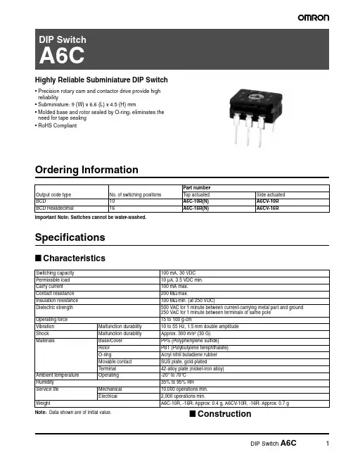
Highly Reliable Subminiature DIP Switch•Precision rotary cam and contactor drive provide high reliability•Subminiature: 9 (W) x 6.6 (L) x 4.5 (H) mm•Molded base and rotor sealed by O-ring; eliminates the need for tape sealing •RoHS CompliantOrdering InformationImportant Note: Switches cannot be water-washed.Specifications■CharacteristicsNote: Data shown are of initial value.■ConstructionOutput code type No. of switching positions Part numberTop actuated Side actuated BCD10A6C-10R(N)A6CV-10R BCD Hexadecimal16A6C-16R(N)A6CV-16RSwitching capacity 100 mA, 30 VDC Permissible load 10 µA, 3.5 VDC min.Carry current 100 mA max.Contact resistance 200 M Ω max.Insulation resistance 100 M Ω min. (at 250 VDC)Dielectric strength 500 VAC for 1 minute between current-carrying metal part and ground 250 VAC for 1 minute between terminals of same pole Operating force 15 to 100 g-cmVibration Malfunction durability 10 to 55 Hz, 1.5 mm double amplitude Shock Malfunction durability Approx. 300 m/s 2 (30 G)MaterialsBase/Cover PPS (Polyphenylene sulfide)Rotor PBT (Polybutylene terephthalate)O-ringAcryl nitril butadiene rubber Movable contact SUS plate, gold-plated T erminal42-alloy plate (nickel-iron alloy)Ambient temperature Operating-20° to 70°C Humidity 35% to 95% RH Service life Mechanical 10,000 operations min.Electrical 2,000 operations min.WeightA6C-10R, -16R: Approx. 0.4 g, A6CV-10R, -16R: Approx. 0.7 gThe movable contactor is moved as the rotor rotates. The terminalsare insert molded into the base. The rotor is secured by an O-ring and the case and the cover are made of plastic resin. Therefore, the internal mechanism is effectively sealed.DimensionsUnit: mm (inch)■A6C-10R(N)■A6CV-10R■A6C-16R(N)■A6CV-16RTerminal arrangement (bottom view)Mounting holesPCB dimension(Top view)Internal connections(top view)Omron Electronic Components, LLCTerms and Conditions of Sales1.Definitions: The words used herein are defined as follows.(a) Terms:These terms and conditions(b) Seller:Omron Electronic Components LLC and its subsidiaries(c) Buyer:The buyer of Products, including any end user in section III through VI(d) Products:Products and/or services of Seller(e) Including:Including without limitation2.Offer; Acceptance: These Terms are deemed part of all quotations, acknowledgments,invoices, purchase orders and other documents, whether electronic or in writing, relating to the sale of Products by Seller. Seller hereby objects to any Terms proposed in Buyer's purchase order or other documents which are inconsistent with, or in addition to, these Terms.3.Distributor: Any distributor shall inform its customer of the contents after and includingsection III of these Terms.1.Prices; Payment: All prices stated are current, subject to change without notice by Seller.Buyer agrees to pay the price in effect at time of shipment. Payments for Products received are due net 30 days unless otherwise stated in the invoice. Buyer shall have no right to set off any amounts against the amount owing in respect of this invoice.2.Discounts: Cash discounts, if any, will apply only on the net amount of invoices sent toBuyer after deducting transportation charges, taxes and duties, and will be allowed only if (a) the invoice is paid according to Seller's payment terms and (b) Buyer has no past due amounts owing to Seller.3.Interest: Seller, at its option, may charge Buyer 1.5% interest per month or the maximumlegal rate, whichever is less, on any balance not paid within the stated terms.4.Orders: Seller will accept no order less than 200 U.S. dollars net billing.5.Currencies: If the prices quoted herein are in a currency other than U.S. dollars, Buyershall make remittance to Seller at the then current exchange rate most favorable to Seller; provided that if remittance is not made when due, Buyer will convert the amount to U.S. dollars at the then current exchange rate most favorable to Seller availableduring the period between the due date and the date remittance is actually made.ernmental Approvals: Buyer shall be responsible for all costs involved in obtainingany government approvals regarding the importation or sale of the Products.7.Taxes: All taxes, duties and other governmental charges (other than general real propertyand income taxes), including any interest or penalties thereon, imposed directly orindirectly on Seller or required to be collected directly or indirectly by Seller for themanufacture, production, sale, delivery, importation, consumption or use of the Products sold hereunder (including customs duties and sales, excise, use, turnover and license taxes) shall be charged to and remitted by Buyer to Seller.8.Financial: If the financial position of Buyer at any time becomes unsatisfactory to Seller,Seller reserves the right to stop shipments or require satisfactory security or payment in advance. If Buyer fails to make payment or otherwise comply with these Terms or any related agreement, Seller may (without liability and in addition to other remedies) cancel any unshipped portion of Products sold hereunder and stop any Products in transit until Buyer pays all amounts, including amounts payable hereunder, whether or not then due, which are owing to it by Buyer. Buyer shall in any event remain liable for all unpaid accounts.9.Cancellation; Etc: Orders are not subject to rescheduling or cancellation unless Buyerindemnifies Seller fully against all costs or expenses arising in connection therewith. 10.Force Majeure: Seller shall not be liable for any delay or failure in delivery resulting fromcauses beyond its control, including earthquakes, fires, floods, strikes or other labor disputes, shortage of labor or materials, accidents to machinery, acts of sabotage, riots, delay in or lack of transportation or the requirements of any government authority.11.Shipping; Delivery: Unless otherwise expressly agreed in writing by Seller:(a) All sales and shipments of Products shall be FOB shipping point (unless otherwisestated in writing by Seller), at which point title to and all risk of loss of the Products shall pass from Seller to Buyer, provided that Seller shall retain a security interest in theProducts until the full purchase price is paid by Buyer;(b) Delivery and shipping dates are estimates only; and(c) Seller will package Products as it deems proper for protection against normalhandling and extra charges apply to special conditions.12.Claims: Any claim by Buyer against Seller for shortage or damage to the Productsoccurring before delivery to the carrier must be presented in detail in writing to Seller within 30 days of receipt of shipment.1.Suitability: IT IS THE BUYER’S SOLE RESPOINSIBILITY TO ENSURE THAT ANYOMRON PRODUCT IS FIT AND SUFFICIENT FOR USE IN A MOTORIZED VEHICLE APPLICATION. BUYER SHALL BE SOLELY RESPONSIBLE FOR DETERMINING APPROPRIATENESS OF THE PARTICULAR PRODUCT WITH RESPECT TO THE BUYER’S APPLICATION INCLUDING (A) ELECTRICAL OR ELECTRONICCOMPONENTS, (B) CIRCUITS, (C) SYSTEM ASSEMBLIES, (D) END PRODUCT, (E) SYSTEM, (F) MATERIALS OR SUBSTANCES OR (G) OPERATING ENVIRONMENT.Buyer acknowledges that it alone has determined that the Products will meet theirrequirements of the intended use in all cases. Buyer must know and observe allprohibitions of use applicable to the Product/s.e with Attention: The followings are some examples of applications for whichparticular attention must be given. This is not intended to be an exhaustive list of all possible use of any Product, nor to imply that any use listed may be suitable for any Product:(a) Outdoor use, use involving potential chemical contamination or electricalinterference.(b) Use in consumer Products or any use in significant quantities.(c) Energy control systems, combustion systems, railroad systems, aviation systems,medical equipment, amusement machines, vehicles, safety equipment, andinstallations subject to separate industry or government regulations.(d) Systems, machines, and equipment that could present a risk to life or property.3.Prohibited Use: NEVER USE THE PRODUCT FOR AN APPLICATION INVOLVINGSERIOUS RISK TO LIFE OR PROPERTY WITHOUT ENSURING THAT THE SYSTEM AS A WHOLE HAS BEEN DESIGNED TO ADDRESS THE RISKS, AND THAT THE PRODUCT IS PROPERLY RATED AND INSTALLED FOR THE INTENDED USEWITHIN THE OVERALL EQUIPMENT OR SYSTEM.4.Motorized Vehicle Application: USE OF ANY PRODUCT/S FOR A MOTORIZEDVEHICLE APPLICATION MUST BE EXPRESSLY STATED IN THE SPECIFICATION BY SELLER.5.Programmable Products: Seller shall not be responsible for the Buyer's programming ofa programmable Product.1.Warranty: Seller's exclusive warranty is that the Products will be free from defects inmaterials and workmanship for a period of twelve months from the date of sale by Seller (or such other period expressed in writing by Seller). SELLER MAKES NO WARRANTY OR REPRESENTATION, EXPRESS OR IMPLIED, ABOUT ALL OTHER WARRANTIES, NON-INFRINGEMENT, MERCHANTABILITY OR FITNESS FOR A PARTICULARPURPOSE OF THE PRODUCTS.2.Buyer Remedy: Seller's sole obligation hereunder shall be to replace (in the formoriginally shipped with Buyer responsible for labor charges for removal or replacement thereof) the non-complying Product or, at Seller's election, to repay or credit Buyer an amount equal to the purchase price of the Product; provided that there shall be noliability for Seller or its affiliates unless Seller's analysis confirms that the Products were handled, stored, installed and maintained and not subject to contamination, abuse,misuse or inappropriate modification. Return of any Products by Buyer must beapproved in writing by Seller before shipment.3.Limitation on Liability: SELLER AND ITS AFFILIATES SHALL NOT BE LIABLE FORSPECIAL, INDIRECT, INCIDENTAL OR CONSEQUENTIAL DAMAGES, LOSS OF PROFITS OR PRODUCTION OR COMMERCIAL LOSS IN ANY WAY CONNECTED WITH THE PRODUCTS, WHETHER SUCH CLAIM IS BASED IN CONTRACT,WARRANTY, NEGLIGENCE OR STRICT LIABILITY. FURTHER, IN NO EVENT SHALL LIABILITY OF SELLER OR ITS AFFILITATES EXCEED THE INDIVIDUAL PRICE OF THE PRODUCT ON WHICH LIABILITY IS ASSERTED.4.Indemnities: Buyer shall indemnify and hold harmless Seller, its affiliates and itsemployees from and against all liabilities, losses, claims, costs and expenses (including attorney's fees and expenses) related to any claim, investigation, litigation or proceeding (whether or not Seller is a party) which arises or is alleged to arise from Buyer's acts or omissions under these Terms or in any way with respect to the Products.1.Intellectual Property: The intellectual property embodied in the Products is the exclusiveproperty of Seller and its affiliates and Buyer shall not attempt to duplicate it in any way without the written permission of Seller. Buyer (at its own expense) shall indemnify and hold harmless Seller and defend or settle any action brought against Seller to the extent that it is based on a claim that any Product made to Buyer specifications infringedintellectual property rights of another party.2.Property; Confidentiality: Notwithstanding any charges to Buyer for engineering ortooling, all engineering and tooling shall remain the exclusive property of Seller. All information and materials supplied by Seller to Buyer relating to the Products areconfidential and proprietary, and Buyer shall limit distribution thereof to its trustedemployees and strictly prevent disclosure to any third party.3.Performance Data: Performance data is provided as a guide in determining suitabilityand does not constitute a warranty. It may represent the result of Seller's test conditions, and the users must correlate it to actual application requirements.4.Change In Specifications: Product specifications and description may be changed at anytime based on improvements or other reasons. It is Seller’s practice to change part numbers when published ratings or features are changed, or when significantengineering changes are made. However, some specifications of the Product may be changed without any notice.5.Errors And Omissions: The information on Seller’s website or in other documentationhas been carefully checked and is believed to be accurate; however, no responsibility is assumed for clerical, typographical or proofreading errors or omissions.6.Export Controls: Buyer shall comply with all applicable laws, regulations and licensesregarding (a) export of the Products or information provided by Seller; (b) sale ofProducts to forbidden or other proscribed persons or organizations; (c)disclosure to non-citizens of regulated technology or information.1.Waiver: No failure or delay by Seller in exercising any right and no course of dealingbetween Buyer and Seller shall operate as a waiver of rights by Seller.2.Assignment: Buyer may not assign its rights hereunder without Seller's written consent.w: These Terms are governed by Illinois law (without regard to conflict of laws). Federaland state courts in Illinois have exclusive jurisdiction for any dispute hereunder.4.Amendment: These Terms constitute the entire agreement between Buyer and Sellerrelating to the Products, and no provision may be changed or waived unless in writing signed by the parties.5.Severability: If any provision hereof is rendered ineffective or invalid, such provision shallnot invalidate any other provision.Certain Precautions on Specifications and UseOMRON ON-LINEGlobal - USA - Cat. No. J01C-E-01Printed in USAOMRON ELECTRONIC COMPONENTS LLC55 E. Commerce Drive, Suite B Schaumburg, IL 60173847-882-228801/07 Specifications subject to change without noticeComplete “Terms and Conditions of Sale” for product purchase and use are on Omron’s website at – under the “About Us” tab, in the Legal Matters section.ALL DIMENSIONS SHOWN ARE IN MILLIMETERS.T o convert millimeters into inches, multiply by 0.03937. To convert grams into ounces, multiply by 0.03527.。
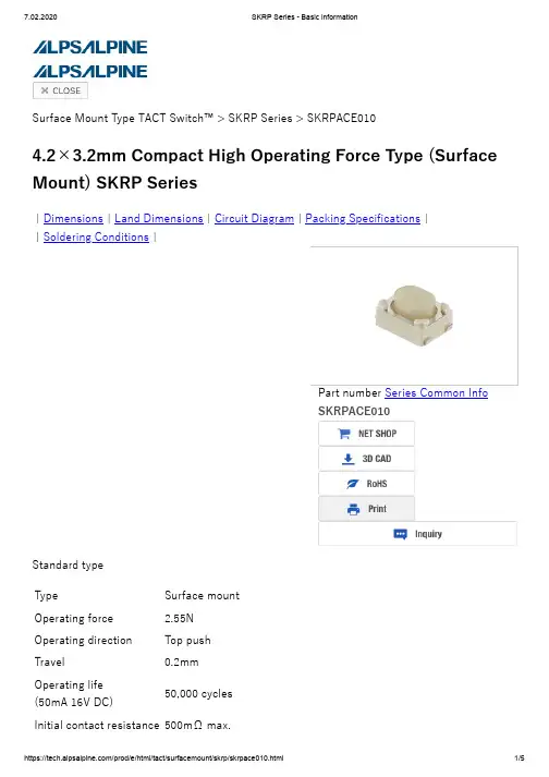
|Dimensions |Land Dimensions |Circuit Diagram |Packing Specifications |Soldering Conditions Surface Mount Type TACT Switch™ > SKRP Series > SKRPACE0104.2×3.2mm Compact High Operating Force Type (Surface Mount) SKRP Series||Standard typeTypeSurface mount Operating force2.55N Operating directionTop push Travel0.2mm Operating life(50mA 16V DC)50,000 cyclesInitial contact resistance 500mΩ max.Part number Series Common InfoSKRPACE010Stem color NaturalSeries type Sharp feeling typeOperating temperaturerange -30℃ to +85℃Rating (max.)50mA 16V DCRating (min.)10µA 1V DCElectrical performance Insulationresistance 100MΩ min. 100V DC for 1min.Voltageproof 250V AC for 1 min.Durability Vibration 10 to 55 to 10Hz/min., the amplitude is 1.5mm for all thefrequencies, in the 3 direction of X, Y and Z for 2 hoursrespectivelyEnvironmental performance Cold -30±2℃ for 96hDry heat 80±2℃ for 96hDampheat 60±2℃, 90 to 95%RH for 96hMinimum order unit (pcs.)Japan 4,000Export 4,000DimensionsLand DimensionsViewed from mounting face. Circuit DiagramPacking Specifications TapingNumber of packages (pcs.)1 reel4,0001 case / Japan40,0001 case / export packing40,000Tape width (mm)12Export package measurements (mm)395×395×205Soldering ConditionsCondition for Reflow1. Heating methodDouble heating method with infrared heater.2. Temperature measurementThermocouple 0.1 to 0.2 Φ CA(K) or CC(T) at solder joints (copper foil surface). A heat resisting tape should be used for fix measurement.3. Temperature profile(1) The above temperature shall be measured of the top of switch. There are cases where PC board's temperature greatly differs from that of the switch, depending on the material, size, thickness of PC board's and others. Care, should be taken to prevent the switch's surface temperature from exceeding 260℃.(2) Soldering conditions differ depending on reflow soldering machines. Prior verification of soldering condition is highly recommended.Manual SolderingItems ConditionSoldering temperature350℃ max.Duration of soldering3s max.Capacity of soldering iron60W max.1. Do not washing the TACT Switch™.2. Prevent flux penetration from the top side of the TACT switch™.3. Switch terminals and a PC board should not be coated with flux prior to soldering.4. The second soldering should be done after the switch returns to normal temperature.Notes are common to this series/models.1. This site catalog shows only outline specifications. When using the products, pleaseobtain formal specifications for supply.2. Please place purchase orders for taping products per minimum order unit (1 reel or acase).3. For φ330mm diameter reel requirements, please contact us.Inquiries about ProductsInquiryCOPYRIGHT© 2020 ALPS ALPINE CO., LTD。
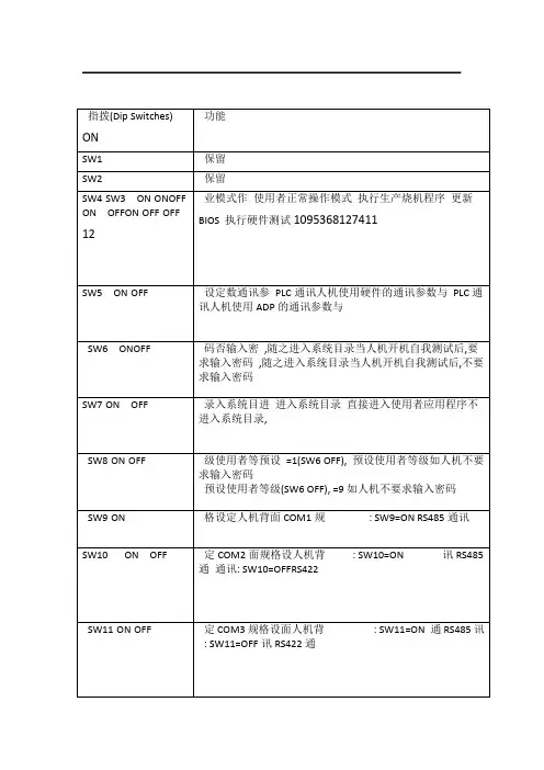
指拨(Dip Switches) 功能
U盘备份数据-----转载海泰克触摸屏用(2011-10-27 09:42:19)转载▼
标签:
触摸屏数据备份盘u杂谈年瑞典系列人机产品在大陆的推广和销售。
2005自1996年天津罗升开始负责HITECH PWS两大系列在中PWSEXTER和HMIBeijer成功并购HITECH(海泰克)后,目前旗下的产品:罗升系列产品的加入,EXTER国大陆的销售和服务全部由天津罗升企业有限公司负责。
由于的产品线更加的齐全。
穿透和透明模式举例说明下面针对BEIJER T70功能:
将历史缓冲区的数据自动存储到CF卡或U盘,此功能可以将历史数据自动保存到CF卡或U盘,能够以EXCEL表的形式在电脑中读取,方便客户存储和查看大量历史数据。
使用说明:
1.在工作参数设定中设定纪录缓冲区,在“备份存储装置”中选择“CF Card”或“USB Memory Card”这样,人机每采样一次,就会将数据自动备份到CF卡或者U盘,如图一。
图一
2.点击图一中的“编辑”,为要取样的数据取名字,如图二:
A:名称,为取样数据定义名称,中英文都可以。
word:字位置,该纪录缓冲区的第几个B.
C:格式,取样数据的格式。
D:长度,可以为单字也可以为双字。
图二
3.如此设置之后,人机会自动将纪录缓冲区中数据存保存到CF或U盘中,每个纪录缓冲区形成一个EXCEL文件,如图三
图三
4.各取样数据以图二中所取名字存在于CF卡,如图四
图四
Demo见demo21(数据保存至U盘只需要将“备份存储装置”更改为“USB Memory STICK”,其余操作与保存至CF卡一样)。
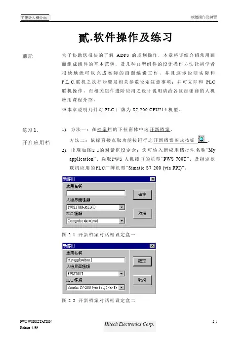
貳.软件操作及练习前言:为了协助您很快的了解ADP3的规划操作,本章将详细介绍常用画面组成组件的基本范例,及几种典型组件的设计操作方法让初学者很快地就可以完成实际的画面编辑工作,并且逐步说明实际和P.L.C.联机之执行步骤及相关参数设定注意事项;并可立即和PLC联机操作。
而相关组件进阶应用之设计说明请洽各区经销商的人机应用课程介绍。
※本章说明乃针对PLC厂牌为S7-200 CPU214机型。
练习1、开启应用档1). 方法一:在档案栏的下拉窗体中选开新档案。
方法二:鼠标直接点取功能按钮行之开新档案图式按钮。
2). 出现如图2-1的对话框设定盒;您可输入新应用档批注名称“Myapplication”、选取PWS-人机接口的机型“PWS-700T”、及指定欲联机应用的PLC厂牌机型“Simatic S7-200 (via PPI)”。
图2-1 开新档案对话框设定盒一图2-2 开新档案对话框设定盒二3、当新应用文件被开启后,屏幕会出现图2-3 ADP3画面层程序窗口。
图2-3 ADP3程序窗口_应用文件层窗口练习2、认识画面组件可对应的PLC资料地址在ADP3开始规划画面组件前,设计者必须清楚了解可以使用的PLC资料地址的格式及范围;在ADP3软件中大部份均依照PLC本身原厂格式,所以您可以参考PLC原厂技术手册;下表所列为针对SIEMENS S7-200 CPU216:表1. 在ADP3软件规划可以使用的P.L.C.缓存器地址的格式及范围缓存器种类代号格式编号范围资料长度Remark Input Image IWn n=0-6 WordInput Image IDn n=0-4 Double WordOutput Image QWn n=0-6 WordOutput Image QDn n=0-4 Double WordInternal Bits MWnn nn=0-30 WordInternal Bits MDnn nn=0-28 Double WordSpecial Bits SMWnnn nnn=0-27 Word Read only Special Bits SMWnnn nnn=28-192 WordSpecial Bits SMDnnn nnn=28-190 Double WordData Area VWnnnn nnnn=0-5118 WordData Area VDnnnn nnnn=0-5116 Double WordSpecial S SWnn nn=0-30 WordSpecial S SDnn nn=0-28 Double WordTimer Tnnn nnn=0-255 WordCounter Cnnn nnn=0-255 WordAnalog input word AIWnn nn=0-30 Word Read only Analog output word AQWnn nn=0-30 Word Read only功能圖式按鈕行開新檔案圖式按鈕標題行存檔圖式按鈕開新畫面圖式按鈕呼叫畫面圖式按鈕呼叫舊檔圖式按鈕注意1:CPU-212 不能使用AIW, AQW, SW, SD注意2:PLC缓存器地址的范围须受限于P.L.C主机CPU的机型,应用时,请限制不可超过该CPU本身的最大值,否则会通讯失败。
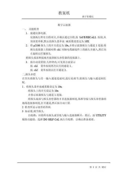
数字示波器一,功能检查1.接通仪器电源.仪器执行所有自检项目,并确认通过自检,按SA VE/RECALL按钮,从顶部菜单框,默认的探头菜单衰减系数设值定为10X.2.将p2100探头上的开关设定为10x,并将示波器探头与通道1连接.将探头连接器上的插对准ch1同轴电缆插接件上的插头并插入,然后向右旋转以拧紧探头.把探头端部和接地夹接到探头补偿器的连接器上.3.按自动设置钮.几秒钟内,可见到方波显示按ch1 菜单按钮两次以关闭通道1 ,按ch2 菜单按钮以打开通道2..二,探头补偿在首次将探头与任一输入通道连接时,进行此调节,使探头与输入通道相匹配.1 . 将探头菜单衰减系数设定为10x,将探头上的开关设定为10x并将示波器探头与通道1连接.将探头端部与探头补偿器的5伏连接器相连,基准导线与探头补偿器的地线连接器相连,打开通道,然后按自动门置.2 检查所显示波形的形状.3 如必要,调节探头.自校准:应将所有探头或导线与输入连接器断开,然后,按UTILITY 辅助功能钮,选择DO SELF CAL执行自校准,以确认准备就绪。
数字示波器三.探头衰减系数设定:探头有多种衰减系数,它们会影响示波器垂直标尺度数.如改变(检查)探头衰减系数设定值,按所使用通道的---垂直功能菜单钮, 然后按---探头钮旁的选择钮,直至显示正确的设定值.该设定在再次改变前一直有效.注意:出厂时预定值为10x.确认在探头上衰减开关的设定与示波器上探头探头菜单的选项相同.探头开关的设定值为1 和10.注意:衰减开关,设定在1 时探头将示波器的带宽限制在7兆,欲全带宽时,必将开关设定为10-.四,基本概念(一),触发:触发决定了示波器何时开始采集数据和显示波形,一旦触发被正确设定.它可以把不稳定的显示或黑屏转换成有意义的波形.示波器在开始采集数据时,先收集足够的数据用来在触发点的左方画出波形,示波器在等待触发条件发生的同时连续地采集数据.当检测到触发后,示波器连续地采集足够的数据以在触发点的右方画出波形.1.信源:触发可从多种信源得到:输入通道,市电,外部触发.1)输入通道:最常用, 可任选. 被选中作为触发信源的通道,无论其输入是否被显示.都能正常工作.2)市电:用来显示信号与动力电,如照明设备和动力提供设备,之间的频率关系.示波器将产触发,无需人工输入触发信号.3)外部触发: 用于在两个通道上采集数据的同时在第三个通道上输入触发.2.触发类型:1)边沿触发:可利用模拟和数字测试电路进行边沿触发,当触发输入沿给方向通过某一给定电平时,边沿触发发生.2)视频触发: 标准视频信号可用来进行场行触发.3.触发方式:1)自动触发:使得示波器即使在没有检测到触发条件的情况下也能取到波形,当示波器在一定等待时间”该时间由时基设置决定”器将进行强制触发.当强制进行无效触发时,示波器不能使波形同步,则显示有波形将卷在一起,当有效触发发生时,显示器上的波形是稳定的.可用自动方式来监测幅值电平等可能导致波形显示发生卷滚的因素.2)正常触发: 示波器在正常触发方式下只有当其被触发时才能获取到波形,无触发时,示波器将显示原有波形而获取不到新波形.3)单次触发:在单次触发方式下,用户每按下一次”运行”按钮,示波器将检测到一次触发获取一个波形.示波器采集到的数据依赖于获取方式.4.释抑:释抑时间—每次采集之后的一段时间.为了产生稳定的显示波形的需要.释抑周期可被用来阻止脉冲序中第一个脉冲之外的其它脉冲上的触发.这样,示波器将总是只显示第一个脉冲.为获得释抑控制,按下HORIZONTAL “释抑”,并用释抑旋钮改变释抑周期.5.耦合触发耦合决定信号的何种分量被传送到触发电路,耦合类型包括直流,交流,噪声抑制,高频抑制和低频抑制.1)直流:允许所有的分量通过.2)交流: 阻止直流分量通过.3)噪声抑制:降低触灵敏度并要求较高的信号幅值才能形成稳定触发,从而减少了在噪声上信号错误触发的可能性.4)高频抑制:阻止信号的高频部分通过,只允许低频分量通过.5)低频抑制: 作用效果与高频抑制耦合相反.6.斜率和电平斜率控制钮决定示波器的触发点在信号上升沿或在下降沿,欲获得触发斜率控制,按下”触发菜单”按钮选择”边沿”并用”斜率”按钮选择上升或下降.电平控制钮决定触发点在,边沿上的确切位置,欲获得触发电平控制,按下”HORIZONTAL”菜单按钮,选择“电平”并旋转”电平”旋钮改变数值.数字示波器(二)采集数据采集模拟数据时,本示波器将其转换成数字形式.时基设置将影响采集数据的速度.1,采集数据有三种不同的方式:1)采样: 在该获取方式下,示波器按相等的时间间隔对信号采样以重建波形.这种方式在大多数情况下正确地表示了模拟信号.这种方式不能获取模拟信号在两次采样时间间隔内发生的迅速变化, 从而导至混淆,并有可能丢失信号中的窄脉冲.2)峰值检测: 示波器采集每一采样间隔中输入信号的最大值,并用采样数据显示波形.这样,示波器可以获取和显示在采样方式下可能丢失的窄脉冲,但噪场将比较明显.3)平均值: 示波器获取若干波形,然后取平均,并显示平均后的波形,可用这种方式减少随机噪声.2.时基通过在离散点上对输入信号的采样将波形数字化,时基控制数字化的频率.使用“秒/刻度”旋钮调整时基到某一水平刻度以适合用户需要.(三).标度和定位波形通过调整波形的刻度和位置可改变其在导电屏幕上的显示.刻度被改变时,显示波形的尺寸将被放大或缩小.位置改变时,波形将上下左右移动.1.垂直刻度和位置通过上下移动波形可以改变显示波形的垂直位置,为对比数据,可将波形上下对齐.改变形的垂直刻度时,显示波形将相对接地电平收缩或扩张.2.水平刻度和位置:触发前后可通过调整”水平位置”控制钮查看波形数据, 改变波形的水平位置实际改变的是触发与显示区中心的时间偏差使用”秒/刻度”旋钮可改变所有波形的水平刻度.如查看波形的一个周期以测量其上升沿的对冲.数字示波器(四)测量:示波器所显示的电压—时间坐标图,可用来测量所显示的波形。
22 mm PILOT DEVICES OMPBD7 SERIESPUSHBUTTONS AND SELECTOR SWITCHESOmegas rugged OMPBD7 pilot devices offer maximum flexibility and a wide choice for all applications. This 22 mm line is aesthetically appealing and modularly designed to make assembly and interchangeability easy. The OMPBD7 operators are available in two different body styles to meet every application need. Both operators exhibit a new lower profile stylish appearance while maintaining the rugged performance necessary for demanding environments.Two Operator TypesOMPBD7P is a plastic operator with acaptive black plastic front bezel. Constructed of high-grade thermoplastics, the OMPBD7P is the corrosion resistant solution for harsh environments. For super tough applications,the OMPBD7M has a die-cast zinc housing and mounting ring for a rugged durability.Both are finished with corrosion resistant chrome plating. The OMPBD7M also features a captive shiny metal bezel for a polished appearance.Quick, Easy InstallationA standard anti-rotation tab keeps front elements from turning or falling off the control panel, making it possible for one person to install all OMPBD7components even if the front and rear panel are not accessible at the same time. A central mounting ring allows for quick installation and removal of all OMPBD7 operators. All back-of-panel components including contact blocksand power module elements snap-on and are readily accessible and interchangeable without removing the pilot device from the panel.Tool-Less Mounting LatchThe OMPBD7 “tool-less” mounting latch mates the front element with the contact blocks and other back-of-panel components.The mounting latch is available in a plastic and metal design. The latches are easily installed with a “click” and removed by pushing a rotating collar to the right. Quick,reliable and strong, it’s the best pilot device mounting latch available in the industry.Long Electrical and Mechanical LifeMost OMPBD7 operators have a mechanical of ten million operations… five million contact blocks. Electrical life ranges from 500,000 cycles at 3 A to ten million at 0.1 A.The OMPBD7 line is also electronics compatible with self cleaning contacts.Environmental RatingsFront elements, including pushbuttons,mushroom operators and selector switches,are IP66 rated against submersion, oil and dirt, making them reliable in the toughest industrial environments. Metal operators are NEMA 4/13 rated and plastic operators are rated NEMA 4/4X/13.OMPBD7M-F3PX10, $24, metal pushbutton,flush button, green,momentary operation with 1 NO contact.OMPBD7P-E4PX10, $24, plastic pushbutton,extended button, red,momentary operation with 1 NO contact.OMPBD7P-MT34PX01, $45,plastic pushbutton, 30 mm mushroom, red, maintained operation with 1 NC contact.Each pushbutton includes one contact block. Units shown with two additionalblocks (pushbuttons may be used with up to 6 contacts)see page I-26.l Heavy-Duty/Oil Tight Pushbuttonsl Quick Installation with Tool-Less Mounting Latchl Plastic Operators: NEMA 4/4X/13and IP65/66 Ratedl Metal Operators: NEMA 4/13 and IP65/66 Ratedl Touch-Safe ContactBlocks–with IP20 Recessed Screw Terminalsl Heavy-Duty Current Rating(10A Continuous)All models shownlarger than actual size.Additional Featuresand OptionsHeavy-Duty Ratings—The OMPBD7 lineis UL 46E, NEMA A600 and Q600 listed. All components carry a 10 Amp continuous current rating, covering all industrial control needs.All Major Approvals—OMPBD7 front elements are UL Recognized, while all OMPBD7 assemblies are UL Approved. The line is also approved by every major international agency making themideal for export requirements.H-Bridge & Gold Plated Contacts—By doubling the available paths for current to pass through the contacts, the standard H-bridge design provides a cleaner current flow. Gold plated contacts quadruple the current paths for increased contact reliability in low voltage applications.Touch-Safe—Back of panel components are finger safe, with IP20 protection.Long Lasting Integral LED Assemblies—Our new LED lamps last up to 11 years! They are conveniently offered as a complete unit for all illuminated operators which include the one piece Integral LED Module. They come in five different colors: amber, blue, green, red and white.OMPBD7M-HM22PX01, two way metal selector switch with long knob.Each unit includes tool-less mounting latch and one normally closed contact block.Shown with two additional (up to 6 total per operator possible) normally opencontact blocks, model OMPBD7-X10, $8.50 each.All shown largerthan actual size.CONTACT BLOCKSRed = normally closed.OMPBD7-X01, $8.50.OMPBD7-X10, $8.50.Green = normally open.Rear view.OMPBD7P-LMM43PX10, $39, plastic pushbutton,green, 40 mm mushroom,momentary operation, one NO contact, shown larger than actual size.OMPBD7P-LE4PX01, $30, plastic pushbutton, extended button, red, momentary operation, one NC contact,shown larger than actual size.22 mm PUSHBUTTONSILLUMINATED PUSHBUTTONS AND E-STOPSOMPBD7-IL Series Start at$51(Specify Model Number)MOST POPULAR MODELS HIGHLIGHTED!used per operator (light module occupies center position).*Insert number for color selection, 2= black, 3= green, 4= red, 5= yellow, 6= blue.Complete with pushbutton and light moduleEach operator includestool-less mounting latch and one contact block. Shown with two additional (up to 4total per operator possible)contact blocks.used per operator.Front-of-Panel (Operators)1Notes:1Performance data given in this publication is provided only as a guide for the user in determining suitability and do not constitute a performance warranty of any kind. Such data may represent the results of accelerated testing at elevated stress levels, and the user is responsible for correlating the data to actual application requirements. ALL WARRANTIES AS TO ACTUAL PERFORMANCE, WHETHER EXPRESS OR IMPLIED, ARE EXPRESSLY DISCLAIMED.2Momentary mushroom operators are IP65, multi-function operators are not Type 13 rated. Plastic operators with keys are not Type 4X rated.3Operating temperatures below 0°C (32°F) are based on the absence of freezing moisture and liquids, UL recognized to 55°C (131°F)incandescent module, max 40°C (104°F).22 mm PILOT DEVICESHEAVY-DUTY/OIL TIGHT PUSHBUTTONSAND SELECTOR SWITCHES OMPBD7 SERIESNon-illuminated pushbuttons, shown on pages I-25 and I-26.Notes:1Performance data given in this publication is provided only as a guide for the user in determining suitability and do not constitute a performance warranty of any kind. Such data may represent the results of accelerated testing at elevated stress levels, and the user is responsible for correlating the data to actual application requirements. ALL WARRANTIES AS TO ACTUAL PERFORMANCE, WHETHER EXPRESS OR IMPLIED, ARE EXPRESSLY DISCLAIMED.4Low voltage contacts are recommended for applications below 17 V, 5 mA.5Wires less than #18 (0.75 mm2) may not hold in terminal securely.CANADA www.omega.ca Laval(Quebec) 1-800-TC-OMEGA UNITED KINGDOM www. Manchester, England0800-488-488GERMANY www.omega.deDeckenpfronn, Germany************FRANCE www.omega.fr Guyancourt, France088-466-342BENELUX www.omega.nl Amstelveen, NL 0800-099-33-44UNITED STATES 1-800-TC-OMEGA Stamford, CT.CZECH REPUBLIC www.omegaeng.cz Karviná, Czech Republic596-311-899TemperatureCalibrators, Connectors, General Test and MeasurementInstruments, Glass Bulb Thermometers, Handheld Instruments for Temperature Measurement, Ice Point References,Indicating Labels, Crayons, Cements and Lacquers, Infrared Temperature Measurement Instruments, Recorders Relative Humidity Measurement Instruments, RTD Probes, Elements and Assemblies, Temperature & Process Meters, Timers and Counters, Temperature and Process Controllers and Power Switching Devices, Thermistor Elements, Probes andAssemblies,Thermocouples Thermowells and Head and Well Assemblies, Transmitters, WirePressure, Strain and ForceDisplacement Transducers, Dynamic Measurement Force Sensors, Instrumentation for Pressure and Strain Measurements, Load Cells, Pressure Gauges, PressureReference Section, Pressure Switches, Pressure Transducers, Proximity Transducers, Regulators,Strain Gages, Torque Transducers, ValvespH and ConductivityConductivity Instrumentation, Dissolved OxygenInstrumentation, Environmental Instrumentation, pH Electrodes and Instruments, Water and Soil Analysis InstrumentationHeatersBand Heaters, Cartridge Heaters, Circulation Heaters, Comfort Heaters, Controllers, Meters and SwitchingDevices, Flexible Heaters, General Test and Measurement Instruments, Heater Hook-up Wire, Heating Cable Systems, Immersion Heaters, Process Air and Duct, Heaters, Radiant Heaters, Strip Heaters, Tubular HeatersFlow and LevelAir Velocity Indicators, Doppler Flowmeters, LevelMeasurement, Magnetic Flowmeters, Mass Flowmeters,Pitot Tubes, Pumps, Rotameters, Turbine and Paddle Wheel Flowmeters, Ultrasonic Flowmeters, Valves, Variable Area Flowmeters, Vortex Shedding FlowmetersData AcquisitionAuto-Dialers and Alarm Monitoring Systems, Communication Products and Converters, Data Acquisition and Analysis Software, Data LoggersPlug-in Cards, Signal Conditioners, USB, RS232, RS485 and Parallel Port Data Acquisition Systems, Wireless Transmitters and Receivers。
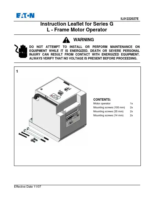
IL01222027EEffective Date 11/07Instruction Leaflet for Series G L - Frame Motor OperatorDO NOT ATTEMPT TO INSTALL OR PERFORM MAINTENANCE ON EQUIPMENT WHILE IT IS ENERGIZED. DEATH OR SEVERE PERSONAL INJURY CAN RESULT FROM CONTACT WITH ENERGIZED EQUIPMENT.ALWAYS VERIFY THAT NO VOLTAGE IS PRESENT BEFORE PROCEEDING.WARNINGRemove existing two screws from primary cover of breaker.Assemble support onto the breaker with four mounting screws supplied. Torque to 0.44 to 0.6 N.m or 4 to 5 in. lb.4•Turn breaker to the “OFF” position first.•Line up breaker handle and molded trigger of motor operator, and position motor operator on the breaker.Mount motor operator to breaker using mounting screws. Torque to 0.44 to 0.6 N.m or 4 to 5 in. lb.SupportMolded Trigger Mounting Screws (14 mm length)Breaker HandleMounting Screws(35 mm length) Mounting Screws(100 mm length)Manual OperationsMove the slide knob to the MANUAL position to expose the manual operating shaft located under the slide knob. The control power supply is cut off automatically.Insert the operating key into shaft slot. Turn the key clockwise to verify the breaker can be closed Leave breaker in the ON position. Press the manual PUSH-TO-TRIP button on the breaker to trip the breaker. Check that the display indicates the TRIP position.Turn the operating key clockwise (approximately 180°) again. This should reset the breaker. Turn the key (Clockwise only)Status IndicationPUSH-TO TRIP ButtonOpetating keyEffective Date 11/07Motor Operator Electrical DataVoltage Frequency Inrush Current 24VDC Application110-127VAC/110-125VDC Application48VDC Application9Lock-Off LeverLOCK-OFFMove slide knob to AUTO position. Pull outthe Lock-Off lever when breaker is in OFFposition, insert one to three padlock shacklesup to 6mm (.25 inch) in diameter.CAUTIONThe motor operator cannot be locked offwhile it is in the ON position.Printed in TQC。

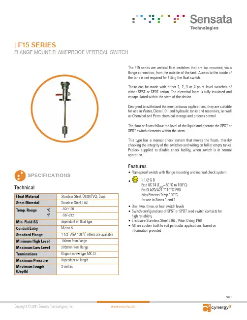
Page 1Copyright © 2021 Sensata Technologies, Inc. Float Material Stainless Steel, D300 (PVC), Buna Stem Material Stainless Steel 316L | F15 SERIESFLANGE MOUNT FLAMEPROOF VERTICAL SWITCHSPECIFICATIONSThe F15 series are vertical float switches that are top mounted, via a flange connection, from the outside of the tank. Access to the inside of the tank is not required for fitting the float switch.These can be made with either 1, 2, 3 or 4 point level switches of either SPST or SPDT action. The electrical loom is fully insulated and encapsulated within the stem of the device.Designed to withstand the most arduous applications, they are suitable for use in Water, Diesel, Oil and hydraulic tanks and reservoirs, as well as Chemical and Petro-chemical storage and process control.The float or floats follow the level of the liquid and operate the SPST or SPDT switch elements within the stem.This type has a manual check system that moves the floats, thereby checking the integrity of the switches and wiring on full or empty tanks. Padlock supplied to disable check facility, when switch is in normal operation.TechnicalFeatures• Flameproof switch with flange mounting and manual check system•II 1/2 G DEx d IIC T4 (T amb =-50°C to 100°C) Ex tD A20/A21 T110°C IP6X Max Process Temp 100°C for use in Zones 1 and 2• One, two, three, or four switch levels• Switch configurations of SPST or SPDT reed switch contacts for high reliability• Enclosure Stainless Steel 316L , Viton O ring IP68• All are custom built to suit particular applications, based oninformation providedPage 2CONTACT US+44 (0)1202 897969*********************Cynergy3 Components Ltd. 7 Cobham Road,Ferndown Industrial Estate, Wimborne, Dorset,BH21 7PE, United KingdomCopyright © 2021 Sensata Technologies, Inc.Sensata Technologies, Inc. (“Sensata”) data sheets are solely intended to assist designers (“Buyers”) who are developing systems that incorporate Sensata products (also referred to herein as “components”). Buyer understands and agrees that Buyer remains responsible for using its independent analysis, evaluation and judgment in designing Buyer’s systems and products. Sensata data sheets have been created using standard laboratory conditions and engineering practices. Sensata has not conducted any testing other than that specifically described in the published documentation for a particular data sheet. Sensata may make corrections, enhancements, improvements and other changes to its data sheets or components without notice.Buyers are authorized to use Sensata data sheets with the Sensata component(s) identified in each particular data sheet. HOWEVER, NO OTHER LICENSE, EXPRESS OR IMPLIED, BY ESTOPPEL OR OTHERWISE TO ANY OTHER SENSATA INTELLECTUAL PROPERTY RIGHT, AND NO LICENSE TO ANY THIRD PARTY TECHNOLOGY OR INTELLECTUAL PROPERTY RIGHT, IS GRANTED HEREIN. SENSATA DATA SHEETS ARE PROVIDED “AS IS”. SENSATA MAKES NO WARRANTIES OR REPRESENTATIONS WITH REGARD TO THE DATA SHEETS OR USE OF THE DATA SHEETS, EXPRESS, IMPLIED OR STATUTORY, INCLUDING ACCURACY OR COMPLETENESS. SENSATA DISCLAIMS ANY WARRANTY OF TITLE AND ANY IMPLIED WARRANTIES OF MERCHANTABILITY, FITNESS FOR A PARTICULAR PURPOSE, QUIET ENJOYMENT, QUIET POSSESSION, AND NON-INFRINGEMENT OF ANY THIRD PARTY INTELLECTUAL PROPERTY RIGHTS WITH REGARD TO SENSATA DATA SHEETS OR USE THEREOF.All products are sold subject to Sensata’s terms and conditions of sale supplied at SENSATA ASSUMES NO LIABILITY FOR APPLICATIONS ASSISTANCE OR THE DESIGN OF BUYERS’ PRODUCTS. BUYER ACKNOWLEDGES AND AGREES THAT IT IS SOLELY RESPONSIBLE FOR COMPLIANCE WITH ALL LEGAL, REGULATORY AND SAFETY-RELATED REQUIREMENTS CONCERNING ITS PRODUCTS, AND ANY USE OF SENSATA COMPONENTS IN ITS APPLICATIONS, NOTWITHSTANDING ANY APPLICATIONS-RELATED INFORMATION OR SUPPORT THAT MAY BE PROVIDED BY SENSATA.Mailing Address: Sensata Technologies, Inc., 529 Pleasant Street, Attleboro, MA 02703, USA.ISO9001CERTIFIED Rev: Cynergy3-f15-v3 03/09/21All are custom built to suit particular applications, based on information provided. Please contact Sensata with your requirements. Information that is normally required:The application and fluid in which the float switch will be used.The Specific Gravity, SG, of the fluid. The maximum temperature of the fluid.Will the float switch be fitted in a tank that is pressurized. The required flange mouth size (If unknown we can specify)The distance from the mounting face of the float switch to the switching point or points.The switching action required at the switch points - ‘make on rise’ or make on fall’Made in the UKLow voltage directive PED directive, where applicable Lloyds Type ApprovedATEX Directive EC Type Examination Cert No BAS01ATEX2265ElectricalApplicable StandardsAll ratings are resistive load only.。
22 mm PILOT DEVICES OMPBD7 SERIESPUSHBUTTONS AND SELECTOR SWITCHESOmegas rugged OMPBD7 pilot devices offer maximum flexibility and a wide choice for all applications. This 22 mm line is aesthetically appealing and modularly designed to make assembly and interchangeability easy. The OMPBD7 operators are available in two different body styles to meet every application need. Both operators exhibit a new lower profile stylish appearance while maintaining the rugged performance necessary for demanding environments.Two Operator TypesOMPBD7P is a plastic operator with acaptive black plastic front bezel. Constructed of high-grade thermoplastics, the OMPBD7P is the corrosion resistant solution for harsh environments. For super tough applications,the OMPBD7M has a die-cast zinc housing and mounting ring for a rugged durability.Both are finished with corrosion resistant chrome plating. The OMPBD7M also features a captive shiny metal bezel for a polished appearance.Quick, Easy InstallationA standard anti-rotation tab keeps front elements from turning or falling off the control panel, making it possible for one person to install all OMPBD7components even if the front and rear panel are not accessible at the same time. A central mounting ring allows for quick installation and removal of all OMPBD7 operators. All back-of-panel components including contact blocksand power module elements snap-on and are readily accessible and interchangeable without removing the pilot device from the panel.Tool-Less Mounting LatchThe OMPBD7 “tool-less” mounting latch mates the front element with the contact blocks and other back-of-panel components.The mounting latch is available in a plastic and metal design. The latches are easily installed with a “click” and removed by pushing a rotating collar to the right. Quick,reliable and strong, it’s the best pilot device mounting latch available in the industry.Long Electrical and Mechanical LifeMost OMPBD7 operators have a mechanical of ten million operations… five million contact blocks. Electrical life ranges from 500,000 cycles at 3 A to ten million at 0.1 A.The OMPBD7 line is also electronics compatible with self cleaning contacts.Environmental RatingsFront elements, including pushbuttons,mushroom operators and selector switches,are IP66 rated against submersion, oil and dirt, making them reliable in the toughest industrial environments. Metal operators are NEMA 4/13 rated and plastic operators are rated NEMA 4/4X/13.OMPBD7M-F3PX10, $24, metal pushbutton,flush button, green,momentary operation with 1 NO contact.OMPBD7P-E4PX10, $24, plastic pushbutton,extended button, red,momentary operation with 1 NO contact.OMPBD7P-MT34PX01, $45,plastic pushbutton, 30 mm mushroom, red, maintained operation with 1 NC contact.Each pushbutton includes one contact block. Units shown with two additionalblocks (pushbuttons may be used with up to 6 contacts)see page I-26.l Heavy-Duty/Oil Tight Pushbuttonsl Quick Installation with Tool-Less Mounting Latchl Plastic Operators: NEMA 4/4X/13and IP65/66 Ratedl Metal Operators: NEMA 4/13 and IP65/66 Ratedl Touch-Safe ContactBlocks–with IP20 Recessed Screw Terminalsl Heavy-Duty Current Rating(10A Continuous)All models shownlarger than actual size.Additional Featuresand OptionsHeavy-Duty Ratings—The OMPBD7 lineis UL 46E, NEMA A600 and Q600 listed. All components carry a 10 Amp continuous current rating, covering all industrial control needs.All Major Approvals—OMPBD7 front elements are UL Recognized, while all OMPBD7 assemblies are UL Approved. The line is also approved by every major international agency making themideal for export requirements.H-Bridge & Gold Plated Contacts—By doubling the available paths for current to pass through the contacts, the standard H-bridge design provides a cleaner current flow. Gold plated contacts quadruple the current paths for increased contact reliability in low voltage applications.Touch-Safe—Back of panel components are finger safe, with IP20 protection.Long Lasting Integral LED Assemblies—Our new LED lamps last up to 11 years! They are conveniently offered as a complete unit for all illuminated operators which include the one piece Integral LED Module. They come in five different colors: amber, blue, green, red and white.OMPBD7M-HM22PX01, two way metal selector switch with long knob.Each unit includes tool-less mounting latch and one normally closed contact block.Shown with two additional (up to 6 total per operator possible) normally opencontact blocks, model OMPBD7-X10, $8.50 each.All shown largerthan actual size.CONTACT BLOCKSRed = normally closed.OMPBD7-X01, $8.50.OMPBD7-X10, $8.50.Green = normally open.Rear view.22 mm SELECTOR SWITCHES2-WAY , 3-WAY AND 4-WAY HEAVY-DUTY /OIL TIGHT LIGHTSOMPBD7-SSSeries Start at$36502-Way Switch Contact Development TableNote: Up to 6 contact blocks can be attached (3 across/2 high). Contact actuation is reversed for spring return left switches.Switching Angle3-Way Switch Contact Development Table OMPBD7M-SM22PX10,ON/OFF, 2-way metal standard knob,NO contact block, $30, shown larger than actual size.* Add suffix “X10”for 1 NO contact block, or “X01”for 1 NC contact block.Each operator includestool-less mounting latch and one contact block. ShownAdd suffix “X10”for 1 NO contact block, or “X01”for 1 NC contact block.Front-of-Panel (Operators)1Notes:1Performance data given in this publication is provided only as a guide for the user in determining suitability and do not constitute a performance warranty of any kind. Such data may represent the results of accelerated testing at elevated stress levels, and the user is responsible for correlating the data to actual application requirements. ALL WARRANTIES AS TO ACTUAL PERFORMANCE, WHETHER EXPRESS OR IMPLIED, ARE EXPRESSLY DISCLAIMED.2Momentary mushroom operators are IP65, multi-function operators are not Type 13 rated. Plastic operators with keys are not Type 4X rated.3Operating temperatures below 0°C (32°F) are based on the absence of freezing moisture and liquids, UL recognized to 55°C (131°F)incandescent module, max 40°C (104°F).22 mm PILOT DEVICESHEAVY-DUTY/OIL TIGHT PUSHBUTTONSAND SELECTOR SWITCHES OMPBD7 SERIESNon-illuminated pushbuttons, shown on pages I-25 and I-26.Notes:1Performance data given in this publication is provided only as a guide for the user in determining suitability and do not constitute a performance warranty of any kind. Such data may represent the results of accelerated testing at elevated stress levels, and the user is responsible for correlating the data to actual application requirements. ALL WARRANTIES AS TO ACTUAL PERFORMANCE, WHETHER EXPRESS OR IMPLIED, ARE EXPRESSLY DISCLAIMED.4Low voltage contacts are recommended for applications below 17 V, 5 mA.5Wires less than #18 (0.75 mm2) may not hold in terminal securely.CANADA www.omega.ca Laval(Quebec) 1-800-TC-OMEGA UNITED KINGDOM www. Manchester, England0800-488-488GERMANY www.omega.deDeckenpfronn, Germany************FRANCE www.omega.fr Guyancourt, France088-466-342BENELUX www.omega.nl Amstelveen, NL 0800-099-33-44UNITED STATES 1-800-TC-OMEGA Stamford, CT.CZECH REPUBLIC www.omegaeng.cz Karviná, Czech Republic596-311-899TemperatureCalibrators, Connectors, General Test and MeasurementInstruments, Glass Bulb Thermometers, Handheld Instruments for Temperature Measurement, Ice Point References,Indicating Labels, Crayons, Cements and Lacquers, Infrared Temperature Measurement Instruments, Recorders Relative Humidity Measurement Instruments, RTD Probes, Elements and Assemblies, Temperature & Process Meters, Timers and Counters, Temperature and Process Controllers and Power Switching Devices, Thermistor Elements, Probes andAssemblies,Thermocouples Thermowells and Head and Well Assemblies, Transmitters, WirePressure, Strain and ForceDisplacement Transducers, Dynamic Measurement Force Sensors, Instrumentation for Pressure and Strain Measurements, Load Cells, Pressure Gauges, PressureReference Section, Pressure Switches, Pressure Transducers, Proximity Transducers, Regulators,Strain Gages, Torque Transducers, ValvespH and ConductivityConductivity Instrumentation, Dissolved OxygenInstrumentation, Environmental Instrumentation, pH Electrodes and Instruments, Water and Soil Analysis InstrumentationHeatersBand Heaters, Cartridge Heaters, Circulation Heaters, Comfort Heaters, Controllers, Meters and SwitchingDevices, Flexible Heaters, General Test and Measurement Instruments, Heater Hook-up Wire, Heating Cable Systems, Immersion Heaters, Process Air and Duct, Heaters, Radiant Heaters, Strip Heaters, Tubular HeatersFlow and LevelAir Velocity Indicators, Doppler Flowmeters, LevelMeasurement, Magnetic Flowmeters, Mass Flowmeters,Pitot Tubes, Pumps, Rotameters, Turbine and Paddle Wheel Flowmeters, Ultrasonic Flowmeters, Valves, Variable Area Flowmeters, Vortex Shedding FlowmetersData AcquisitionAuto-Dialers and Alarm Monitoring Systems, Communication Products and Converters, Data Acquisition and Analysis Software, Data LoggersPlug-in Cards, Signal Conditioners, USB, RS232, RS485 and Parallel Port Data Acquisition Systems, Wireless Transmitters and Receivers。
1. 软件安装及说明安装ADP 编程软件的基本硬件需求如下:1.个人计算机主机:建议使用CPU为80586或更高级机种。
2.内存:建议使用64M以上。
3.硬盘:硬盘必需有60M以上的空间。
4.显示器:一般VGA或SVGA显示卡。
Windows色彩显示请设256 色或以上,屏幕分辨率请设为800×600或以上。
ADP软件的安装程序已被压缩,故需安装才能使用,请使用光盘安装程序,也可由下列网站下载,或向各区域经销商索取。
∙∙∙1.1. 安装ADPADP编程软件,可在下列的 Windows操作系统下工作:∙Windows 95∙Windows 98∙Windows ME∙Windows 2000∙Windows XP安装步骤:1.请先启动您的计算机进入Windows 操作系统。
2.在窗口下 [开始] 栏中选 [执行] 功能项,点 [浏览] 找到光盘路径,执行安装 (Setup.exe) 程序,如图 1。
图 1.Windows下执行安装 (setup.exe) 程序3.按[确定] 钮后,系统会准备开始安装,如错误!未找到引用源。
图 2.ADP 准备开始安装4.然后遵循软件所指定的步骤,在以下的对话框指定欲安装ADP 的硬盘及目录名称,如错误!未找到引用源。
图 3.ADP 软件安装的磁盘驱动器及目录名称5.按 [Next] 钮后,选择所需的 ADP 软件的配套,见错误!未找到引用源。
“Typical” 适合一般性的使用;“Compact”将安装基本功能及“Custom” 将可选择您在 ADP 所需的功能。
图 4.选择所需的 ADP 软件的配套6.如选择“Typical”,按 [Next] 钮后,将自动开始安装,如错误!未找到引用源。
图 5.安装 ADP 软件7.完成安装后,会自动帮您产生ADP程序图标 (ICON)。
8.完成安装后,ADP程序将被建立在所指定的子目录,此时直接用鼠标点取 ADP图标(ICON) 就可执行编程软件了。
HITECH海泰克触摸屏指拨开关的使用说明
指拨开关功能使用的详解
SW1 SW2 : 显示类型出厂默认为SW1=ON;SW2=ON
SW3 SW4 : 运行模式执行使用者应用模式SW3=ON;SW4=ON SW5 : 通讯参数与PLC通讯格式按照硬件系统设置时
SW5=ON;
与PLC通讯格式按照软件系统设置时
SW5=OFF。
SW6 : 密码要求输入密码时SW6=ON;
不要求输入密码时SW6=OFF.
SW7 : 系统菜单开机后腰显示系统菜单时SW7=ON;
开机后直接进入运行模式时SW7=OFF. SW8 : 默认用户等级开机时密码等级设为1时SW8=ON;
开机时密码等级设为3时SW8=OFF. SW9 : COM1通讯方式COM1为RS485通讯方式时
SW9=ON;
COM1为RS422通讯方式时
SW9=OFF.
SW10 : COM2通讯方式COM2为RS485通讯方式时
SW10=ON;
COM2为RS422通讯方式时
SW10=OFF.
PWS3720-TFT 上海亚豪塑胶科技有限公司1#塑料压延机自动计量部分用PWS3261-TFT
2#塑料压延机自动计量部分用PWS3760-TFT 都是在使用中指拨开关1,2,3,4,8,9处于ON位置;而5,6,7,10,处于OFF位置。
附件C.PWS1711/1760安裝說明PWS 1711/PWS 1760是㆒種配備有㆗型5.7”(320Hx240V)LCD 顯示螢幕及類比式觸控面板(Analog Resistive Touch Panel)此面板具有IP65(NEMA 4)的防水防塵工業級設計,適用於各種惡劣環境之高功能㆟機介面,其面板採用高亮度16灰階Mono-STN 或256色的Color-STN,使用者可以根據實際應用要求選擇不同機種。
PWS 1760之機種有LPT 印表埠,不僅可印出完整畫面且更可以自行設計表格,即時列印所須之報表。
PWS 1711是PWS 1700的替代品其軟體功能方面與PWS 1700相容,同樣是㆒種高功能的㆟機介面。
PWS1711/1760產品一般規格Item PWS1711-STN PWS1760-CTN Display Type Monochrome blue mode STN LCD, 16 gray levels Color mode STN LCD,256 gray levels Display Size 5.7" (diagonal)Number of Pixels 320x240Display Adjustment Contrast adjustable from touch screen Back Light CCFT; Life time is 20,000 hours under 25°C and &0%RH humidity Touch Screen Analog resistive type; Max. Number of switches are 40x30 Chemically strengthened glass backing panel;Over 1 million point activations;Hard coat is resistant to most solvents and chemicals Input Power 24VDC ±10%; Isolation; Under 12W CPU Intel 80188SA1100-166; 32bit RISC;166MHz Flash Memory 640K Bytes 1826K Bytes Battery Backed Memory X 64K Bytes Communication Ports COM1/9pin: RS232/RS485; COM2/25pin:RS232/RS422/RS485Printer Port X EPP printer port Front Panel Seal IP65 / NEMA 4Operating Temperature 0~50°C Storage Temperature -20~60°C Ambient Humidity 20-90% RH (non-condensing)Vibration Endurance 0.5mm displacement,10-55Hz, 2hours per X, Y, and Z-axis directions Shock Endurance 10g, 11ms three times in each direction of X, Y, and Z axes RF Emissions CISPR 22, Class A Electrostatic Discharge EN61000-4-2/1995RF Susceptibility ENV50140/1993High Frequency Transients EN61000-4-4/1995Weight 1.25 Kg Cooling Natural cooling C 、前言C-1、產品一般規格PWS WORKSTATIONC-2PWS-1711之外型尺寸及盤面開孔尺寸,如㆘圖之規格。
Hitech 触摸屏使用手册一、概述1.1 感谢您购物Hitech触摸屏产品。
本使用手册旨在向您介绍如何正确使用Hitech触摸屏,并为您提供使用过程中可能遇到的问题的解决方案。
1.2 在使用本产品前,请务必仔细阅读本手册并按照指示进行操作,以确保您能充分利用Hitech触摸屏的功能。
二、产品概述2.1 Hitech触摸屏是一种先进的人机交互设备,能够通过触摸操作实现对设备的控制和指令输入。
2.2 产品特点:灵敏的触摸响应、高清的显示效果、多点触摸支持、耐用的屏幕材料、易于安装和维护。
2.3 适用范围:工业自动化控制、商业展示展览、交互式广告媒体、智能家居控制等领域。
2.4 注意事项:请避免在触摸屏表面使用尖锐物体或过度施加压力,以免损坏屏幕。
三、使用指南3.1 开机和关机a) 开机:按下电源按钮并保持数秒,待屏幕亮起即表示开机成功。
b) 关机:进入系统设置界面,选择“关机”选项完成关机操作。
3.2 触摸操作a) 单点触摸:轻触屏幕即可完成单点触摸操作,适用于简单的选择、拖动等操作。
b) 多点触摸:使用两个以上手指在屏幕上进行操作,可以实现缩放、旋转等操作。
3.3 菜单操作a) 主菜单:轻触屏幕任意位置,弹出主菜单选项,可根据需求选择不同功能。
b) 设置菜单:进入系统设置菜单,可进行屏幕亮度调节、音量调节、语言选择等操作。
3.4 输入操作a) 虚拟键盘:在需要输入文字或数字时,触摸屏会自动弹出虚拟键盘,用户可通过触摸屏进行输入操作。
b) 手写输入:部分Hitech触摸屏产品支持手写输入功能,用户可直接用手指或专用笔进行书写,进行更自然的输入操作。
3.5 网络连接a) 有线连接:通过网线连接,可直接接入局域网或互联网,实现数据传输和上线操作。
b) 无线连接:部分Hitech触摸屏产品支持Wi-Fi连接功能,用户可通过无线网络进行数据传输和上线操作。
3.6 外接设备a) USB接口:部分Hitech触摸屏产品支持USB接口,用户可连接U 盘、键盘、鼠标等外部设备进行数据传输和操作。
型号:TWP-SHi-force –手柄式气动扭矩扳手型号:TWP-S在操作气动扭矩扳手之前,请验证校准证书(与产品一起提供),填写证书上“第一次使用,签字,盖章的日期”。
1.0 检查收到的产品:在收到产品时,目测检查是否有运输造成的损坏。
请注意,运输造成的损坏不包含在产品的保修期内。
如果发现有运输造成的损坏,请立即通知运输公司,并且不要将产品投入使用。
由于运输造成的货物损坏,运输公司应该承担货物维修和更换的费用。
2.0 安全注意事项:在使用设备前,请仔细阅读并遵守所有的操作说明和安全警告。
否则可能会造成设备损坏或者人员伤亡。
操作人员的危险操作,设备缺乏维护及操作不当引起的设备损坏及人员伤伤害,Hi-Force 一律不承担任何责任。
如果对设备的操作有任何疑问,请联系最近的Hi-Force 分公司或者授权经销商。
如果操作者没有接受过高压液压设备的培训和安全使用说明,请联系当地的Hi-Force 分公司或者经销商获取相关培训课程。
操作者在使用设备前,确保已经穿戴好所有个人防护设备:安全鞋,眼镜和保护性手套应该随时都穿戴上。
在操作设备前,完成所有相关风险的评估。
可选型号:操作扭矩扳手前,请详细阅读该操作手册。
如果忽略以下提示,可能会导致严重的身体伤害。
该操作手册是扭矩扳手的一部分,应该放在一个安全的位置以便将来使用,如果扭矩扳手被售卖,租借或者其他方式的转让,操作手册也也应该随扳手一起提供。
只有接受过培训的操作人员才能使用该手动扭矩扳手,操作人员必须知道如何安全的使用扭矩扳手。
没有培训过的操作人员使用扭矩扳手会导致严重的人身伤亡。
用户购买该扭矩扳手时必须确保操作者在使用扭矩扳手前已经完全阅读并理解该操作手册。
必须确保该操作手册随时可供操作者阅读参考。
在开始操作前,必须按照以下步骤检查并确认:-所有可移动零件按照正确次序连接,互相没有堵塞。
- 没有任何受损,磨损的零部件。
-有工具的操作有任何疑惑不要将其投入使用。
海泰克触摸屏用U 盘备份数据-----转载
(2011-10-27 09:42:19)
标签:
自1996年天津罗升开始负责HITECH PWS 系列人机产品在大陆的推广和销售。
2005年瑞典Beijer 成功并购HITECH (海泰克)后,目前旗下的HMI 产品:EXTER 和PWS 两大系列在中国大陆的销售和服务全部由天津罗升企业有限公司负责。
由于EXTER 系列产品的加入,罗升的产品线更加的齐全。
下面针对BEIJER T70穿透和透明模式举例说明
功能: ON
1
10 11 12 2 3 4 5 6 7 8 9
将历史缓冲区的数据自动存储到CF卡或U盘,此功能可以将历史数据自动保存到CF卡或U 盘,能够以EXCEL表的形式在电脑中读取,方便客户存储和查看大量历史数据。
使用说明:
1.在工作参数设定中设定纪录缓冲区,在“备份存储装置”中选择“CF Card”或“USB Memory Card”这样,人机每采样一次,就会将数据自动备份到CF卡或者U盘,如图一。
图一
2.点击图一中的“编辑”,为要取样的数据取名字,如图二:
A:名称,为取样数据定义名称,中英文都可以。
B:字位置,该纪录缓冲区的第几个word。
C:格式,取样数据的格式。
D:长度,可以为单字也可以为双字。
图二
3.如此设置之后,人机会自动将纪录缓冲区中数据存保存到CF或U盘中,每个纪录缓冲区形成一个EXCEL文件,如图三
图三
4.各取样数据以图二中所取名字存在于CF卡,如图四
图四
Demo见demo21(数据保存至U盘只需要将“备份存储装置”更改为“USB Memory STICK”,其余操作与保存至CF卡一样)。