MOOG 伺服比例阀
- 格式:pdf
- 大小:1.76 MB
- 文档页数:8
比例阀维护和修理中需要注意哪些事项比例阀维护和修理保养Parker比例阀维护和修理中需要注意哪些事项电液伺服阀对液压系统有很高的要求,介质的颗粒清洁度要求不低于NAS6级。
伺服阀工作性能的稳定性很大程度上倚靠于液压系统介质品质的高处与低处。
除在液压泵站泵的出口安装出名义过滤精度为3bLm的过滤器外,在伺服阀的进口前还装有一个3pm的二级保护过滤器。
穆格伺服维护和修理中需要注意下列问题:1、伺服阀在发生故障前,往往可依据很多途径判定出它的工作状态,为此,预见性的更换较之被动更换,更能保证整个系统的工作稳定性。
2、在环境湿度较高的地方使用该阀时,应在油箱上安装可除湿的呼吸器,以保证介质的含水量不超过0.006%。
3、定期取样化验液压介质的颗粒污染度,并依据化验结果,订立出一个较合理的油品及滤芯更换周期,以保证介质的颗粒污染度不低于NAS6级。
4、更换下来的伺服阀,一般情况下经过修理便可再次使用,送专业厂家检修为宜,以确保伺服阀的性能牢靠。
电液比例阀进展历程特别悠久,它是一种输出量与输入信号成比例的液压阀,了解比例阀维护和修理及工作原理特别紧要。
它广泛应用于对液压参数进行连续掌控或程序掌控,电液比例阀工作原理和结构形式、工作特点,对比例阀负载感应和压力补偿原理进行了剖析讨论。
对电液比例阀不同应用,特别是工程机械先导把持和遥控方面应用进行了论述电液比例阀对简化工程机械操作、提率和作业精度以及实现智能化作业都有着极其紧要意义,其性能进一步提高和应用范畴日益拓宽必将使工程机械产品技巧水平到较大程度提高。
某推土机推土铲手动与电液比例先导把持实例。
当二位三通电磁阀不通电时,先导压力与手动减压式先导阀相通,梭阀选择来自手动先导阀压力对液动换向阀进行把持;当二位三通电磁阀通电时,先导把持压力油通向三通比例减压式先导阀,梭阀对液动换向阀进行把持。
电液比例阀是阀内比例电磁铁输入电压信号产生相应动作,使工作阀阀芯产生位移,阀口尺寸发生更改并以此完成与输入电压成比例压力、流量输出元件。

M040-120-001 阀测试仪使用手册目录章节内容页号1 简述 32 技术参数3 测试仪、阀和设备的接线4 设备(在线)操作模式5 测试仪(离线)测试模式6 外部24V电源7 连线列表8 性能测试第一章简述1.1 M040-120阀测试仪(在下述中简称为简称为“测试仪”)是MOOG公司为测试MOOG全系列的比例阀、伺服阀而开发的专用仪器。
它具有多种测试功能即使安装在设备上的阀处于运行中,它可以按以下两种模式工作:A 设备(在线)模式:设备和阀正常运行,测试仪安装在设备和阀之间,这样设备发给阀和接受阀的所有信号还是像正常运行一样连接,测试仪监控设备发出的信号和阀反馈的信号,这样就可以检查阀的性能。
B 测试仪(离线)模式:在这种模式中,测试仪可以自己发出指令给阀并监控阀反馈的信号。
阀虽然仍安装在设备上,但是来自设备的指令信号已被切断。
之所以测试时仍将阀安装在设备上是由于这样可以观察设备对测试仪发出指令的反应。
1.2 无论在线还是离线模式,阀测试仪的电源都是由设备提供。
即使设备不提供24V电源,也可以在前面板的电源接口从外部引入24V电源来驱动阀。
1.3 测试仪用两条线将设备和阀连接起来,首先移开阀上的设备连接线,然后用测试仪的设备线接在设备上、阀线接在阀上。
每种阀有专门的连接线缆,详细的线缆清单参见第七章。
1.4 在阀的正面板上有6个功能块:1.电源/阀正常2.控制3.使能4.流量设定5.压力设定6.反馈1.4.1 电源/阀正常-------- Power/Valve OK24V指示灯亮表示设备上的24V电源和测试仪前面板的连接正常;check 指示灯亮表示阀内部的±15V电源正常,注意该组电源仅内部使用,不用于驱动阀的电源;valve ok 指示灯亮表示阀的逻辑信号为正。
1.4.2 控制 -----------------Control此切换可以选择两种工作模式:测试仪模式,测试仪发出压力P、流量Q和阀使能命令,随之会从阀上产生压力、位置、使能正常、阀正常,这些信号都可以在阀测试仪上显示出来并传递给设备;设备模式,设备发出压力P、流量Q和阀使能命令给阀,同测试仪模式一样会在阀上产生相同的反应。

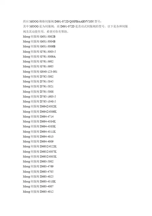
供应MOOG穆格伺服阀D691-072D/Q08FBAABNVS0N型号:其中MOOG是为伺服阀,而D691-072D是直动式伺服阀的型号。
以下是各种伺服阀及其动能作用,希望对你有帮助。
Moog伺服阀 G631-3002BMoog伺服阀 G631-3004BMoog伺服阀 G631-3006BMoog伺服阀 G761-3003-5Moog伺服阀 G761-3009AMoog伺服阀 G761-3602Moog伺服阀 G761-3605Moog伺服阀 G040-123-001Moog伺服阀 D792-5002Moog伺服阀 D791-5045Moog伺服阀 D791-5021Moog伺服阀 D791-5008Moog伺服阀 D765-1603-5Moog伺服阀 D765-1048-5Moog伺服阀 D664Z4382KMoog伺服阀 D664Z4306KMoog伺服阀 D664-4714Moog伺服阀 D664-4384KMoog伺服阀 D664-4383KMoog伺服阀 D664-4311KMoog伺服阀 D664-4013Moog伺服阀 D664-4009Moog伺服阀 D663Z4322KMoog伺服阀 D663Z4307KMoog伺服阀 D663Z4305KMoog伺服阀 D663-5002Moog伺服阀 D663-4769Moog伺服阀 D663-4705Moog伺服阀 D663-4025Moog伺服阀 D663-4318KMoog伺服阀 D663-4007Moog伺服阀 D663-4012Moog伺服阀 D663-306K Moog伺服阀 D663-1922E-4 Moog伺服阀 D662Z4815 Moog伺服阀 D662Z4814 Moog伺服阀 D662Z4813 Moog伺服阀 G761-3009A Moog伺服阀 D662Z4336K Moog伺服阀 G761-3605 Moog伺服阀 D662Z4380 Moog伺服阀 D662Z4384K Moog伺服阀 D662Z4341K Moog伺服阀 M040-104B Moog伺服阀 G040-123-001 Moog伺服阀 D662-4038 Moog伺服阀 D661-4652 Moog伺服阀 D661-4313C Moog伺服阀 D661-4332C Moog伺服阀 D661-4334C Moog伺服阀 D661-4438E Moog伺服阀 D661-4451C Moog伺服阀 D661-4507C Moog伺服阀 D661-4575C Moog伺服阀 D661-4576C Moog伺服阀 D661-4586E Moog伺服阀 D661-4594C Moog伺服阀 D661-4624 Moog伺服阀 D661-4636 Moog伺服阀 D661-4640 Moog伺服阀 D661-4649 Moog伺服阀 D661-4650 Moog伺服阀 D661-4651 Moog伺服阀 D661-4652 Moog伺服阀 D661-4691C Moog伺服阀 D661-4697CMoog伺服阀 D661-4773 Moog伺服阀 D661-4776 Moog伺服阀 D661-4782 Moog伺服阀 D661-4790 Moog伺服阀 D661-4826 Moog伺服阀 D661-4867 Moog伺服阀 D661-5611 Moog伺服阀 D661-5625C Moog伺服阀 D662-1923E-4 Moog伺服阀 D662-4010 Moog伺服阀 D662-4014 Moog伺服阀 D662-4036 Moog伺服阀 D662-4037 Moog伺服阀 D662-4038 Moog伺服阀 D662-4065 Moog伺服阀 D662-4083 Moog伺服阀 D662-4099 Moog伺服阀 D662-4723 Moog伺服阀 D662-4846 Moog伺服阀 D662-4884 Moog伺服阀 D662Z1931E Moog伺服阀 D662Z4017 Moog伺服阀 D662Z4336K Moog伺服阀 D662Z4341K Moog伺服阀 D662Z4378K Moog伺服阀 D662Z4380 Moog伺服阀 D662Z4384K Moog伺服阀 D662Z4813 Moog伺服阀 D662Z4814 Moog伺服阀 D662Z4815 Moog伺服阀 D663-1922E-4 Moog伺服阀 D663-306K Moog伺服阀 D663-344K Moog伺服阀 D663-4007Moog伺服阀 D663-4025 Moog伺服阀 D663-4318K Moog伺服阀 D663-4705 Moog伺服阀 D663-4769 Moog伺服阀 D663-5002 Moog伺服阀 D663-5304K Moog伺服阀 D663Z4305K Moog伺服阀 D663Z4307K Moog伺服阀 D663Z4322K Moog伺服阀 D664-4009 Moog伺服阀 D664-4013 Moog伺服阀 D664-4311K Moog伺服阀 D664-4383K Moog伺服阀 D664-4384K Moog伺服阀 D664-4714 Moog伺服阀 D664Z4306K Moog伺服阀 D664Z4382K Moog伺服阀 D765-019-5 Moog伺服阀 D765-1048-5 Moog伺服阀 D765-1603-5 Moog伺服阀 D791-5008 Moog伺服阀 D791-5045 Moog伺服阀 D791-5021 Moog伺服阀 D792-5002 Moog伺服阀 G040-123-001 D661-4651D661-4652D661-4636D661-4469CD661-4697CD661-4033D661-4059D661-4444CD661-4443CD661-4506CD661-4539CD662Z4311KD662-4010D662Z4336KD663Z4307KD663-4007D663Z4307KD663-4007D634-341CD634-319CD633-333BD791-5009D791-4025D791-4001D791-4002D791-4028D791-4046072-559AD633-312BD633-442BD633-526BD633-419BD633-473BD633-500BD633-314AD633-333BD633-442BD633D633-D2500BD633-D2501BD633-362B/穆格滤芯A67999-065 穆格滤芯A67999-100 穆格滤芯A67999-200穆格滤芯A88594-004 B46634-002B46744-004B61042-005B67728-001B96839-001B97007-061B97027-012B97036-001B97067-111B97069-061C70935-001D631-502FD631-F550FD633-183BD633-303BD633-308BD633-313BD633-315BD633-317BD633-333BD633-380BD633-460BD633-471BD633-472BD633-473BD633-481BD633-495BD633-Z371BD633-501BD633-525BD633D2504BD633-599BD633-603BD634-1035D634-1063D634-400CD634-501AD634-538AD634-543AD634K2000C D635-671ED635-Z681E D691-069DD691-072D-7 D636-225-0000 D661-4003D661-393DD661-4009D661-4023D661-4059D661-4051D661-4055D661-4033D661-4069D661-4070D661-4099D661-4157BD661-4158BD661-4168D661-4178D661-4186D661-4187D661-6405CD661-4303ED661-4313CD661-4332CD661-4334CD661-4341CD661-4438E D661-4443C D661-4444C D661-4451C D661-4506C D661-4507C D661-4575C D661-4576C D661-4577C D661-4586E D661-4594C D661-4624 D661-4636 D661-4640 D661-4649 D661-4650 D661-4651 D661-4652 D661-4688C D661-4691C D661-4697C D661-4729 D661-4773 D661-4776 D661-4782 D661-4790 D661-4826 D661-4867 D661-4931 D661-5611 D661-5625C D661-6313C D661-6324 D661-6326D661-6359D661-6347CD661-6393CD661-6397CD661-6360D661-6372ED661-6428ED662-1923E-4D662-4005 D01HABF6VSX2 D662-4032D662-4010D662-4013D662-4014D662-4036D662-4037D662-4038D662-4050D662-4065D662-4087D662-4083D662-4099D662-4106BD662-4115D662-4118BD662-4124D662-4723D662-4846D662-4884D662-4930D662Z1931ED662Z4017D662Z4310KD662Z4334D662Z4336KD662Z4341K D662-Z4372A D662Z4378K D662Z4380D662Z4384K D662Z4615K D662Z4813D662Z4814D662Z4815D663-1922E-4 D663-306KD663-344KD663-4002D663-4006D663-4007D663-4012D663-4025D663-4031D663-4317D663-4318K D663-4705D663-4769D663-5002D663-5304K D663Z4305K D663Z4307K D663Z4322K D664-4009D664-4013D664-4036D664-4039D664-4311K D664-4383K D664-4384KD664-4714D664-4784D664Z4306KD664Z4382KD664Z4406KD671-0039-0001 D671-0040-0001 D671-0051-0001 D671-0052-0001 D671-0068-0001 D671-0070-0001 D672-0006-0000 D672-0013-0001 D672-0026-0001 D672-0027-0001 D672-0028-0001 D672-0036-0001 D672-0037-0001 D672-5706-0001 D673-0001-0000 D673-5702-0001 D673-5705-0001 D674-0015-0001 D674-5706-0001 D675-5704-0001 D675-5705-0001 D682Z4059D682Z4060D683-4822D683Z4010D684-4912D684Z4011D685-4837DD685-4868D765-019-5D765-1048-5D765-1603-4D765-1603-5D791-5008D791-5021D791-5045D792-4013/S99JOQA6VSX2-B D792-5002D792-5018G040-123-001G631-3002BG631-3004BG631-3005BG631-3006BG631-3008BD636-312-0001D636-313-0001D683-4834G761-3033BG761-3003B5G761-3005BG761-3004B5G761-3009BG761-3602BG761-3605BM040-104BD951-2025-10D951-2007-10D951-2009-10D951-2079-10D952-2001-10D952-2007-10D952-2009-10D953-2001-10D953-2015-10D953-2017-10D954-2003-10D954-2011-10D954-2013-10D955-2003-10D955-2013-10D955-2017-10D956-2003-10D956-2015-10D956-2011-10D956-2017-10D957-2003-10J761-003J761-004G122-824-002072-560AD691-069DD635-671ED691-072DD062-512F760F911A-HP5?S10K0GM4VPL D633-632D663-339NC072-560A,替代型号072-1203-9 D635-671ED061-9321D061-823C072-1202-100514 RKP 柱塞泵G631-3705BD662-3303K P01HLMF6NEC2-0 D638-206-0001D638-216-0001G122-202A001L129-034-A007(S/N)L103G122-829-001G122-829-001G123-825-001G761-3001BD684-4915G631-3800BG771K202 S19FOFA4VA4G771K200 S19FOFA4UI4G771K208 S02FOFA4VA4G771K200 H19FOFA4VI4G771K202 H19FOFA4V24G771K208 H02FOFA4V24G772K240 S38FOFA4V14D691-078D-6D953-2017/c HP-RKP045KM28111Z200D952-2001-10 HPR18A1 RKP032KM28J1Z00D952-2007-10 HPR18A1 RKP032KM28F2Z00D955-2017-10 HPR18A1 RKP080KM28J1Z00D955-2003-10 HPR18A1 RKP080KM28F2Z00D634直动式伺服阀MOOG D634,直动阀(DDV)是具有内部阀芯位置电反馈的伺服阀。
比例阀与伺服阀有哪些区分美国MOOG比例阀维护保养方法MOOG比例阀的维护和修理:在实际的维护和修理过程中,对存在问题的零部件可以实行直接更换的方法,同时还要对该阀的电气零点和死区进行调整,假如有试验条件还要对维护和修理后阀的行程进行验证。
1、更换存在问题的零部件更换法是对存在问题的零部件进行整体或者部分更换。
更换法在工程机械阀的维护和修理中应用相当广泛,该方法的关键是查找显现问题的部件,找到问题后就可以更换一个与之相同的完好部件,一般情况下通过这种维护和修理方法就能使阀实现正常工作。
导致比例阀失效比较普遍的原因是阀的密封件过度磨损、阀芯位移传感器探针折断,而集成放大器一般不会显现问题。
2、电气零点的调整在工程机械中,比例阀一直工作在恶劣的环境下,而其电气零点易受到外界环境的干扰,MOOG比例阀因此在更换了失效的零部件后就应当对其电气零点进行检测,对不符合要求的应重新标定。
一般检测方法如下:给比例阀的放大器供电(一般情况下0一24V,MOOG比例阀确保阀芯处于断电状态,用万用电表(直流挡,0.25V量程、检测阀芯位移反馈信号,在阀芯没有接受指令的条件下,要求阀芯位移反馈电压为零。
假如不为零就应调整阀芯位移传感器的调整螺母,直至阀芯反馈电压为零。
美国MOOG比例阀维护保养方法1、由于插头组件的接线插座〔基座)老化、接触不良以及电磁铁引线脱焊等原因,导致比例电磁铁不能工作(不能通人电流)。
此时可用电表检测,如发觉电阻无限大,可重新将引线焊牢,修复插座并将插座插牢。
2、线圑组件的故障有线圈老化、线圉烧毁、线圈内部断线以及线圈温升过大等现象。
线圈温升过大会造成比例电磁铁的输出力不足,其余会使比例电磁铁不能工作。
对于线圈温升过大,可检查通人电流是否过大,线圈是否漆包线绝缘不良,阀芯是否因污物卡死等,一一査明原因并排出之;对于断线、烧坏等现象,须更换线圑。
3、衔铁组件的故唪重要有衔铁因其与导磁套构成的摩擦副在使用过程中磨损,导致阀的力滞环加添。
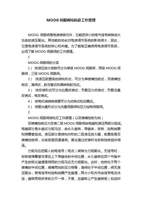
MOOG伺服阀结构及工作原理MOOG伺服阀是电液转换元件,它能把微小的电气信号转换成大功率的液压输出。
其性能的优劣对电液调节系统的影响很大,因此,它是电液调节系统的核心和关键。
为了能够正确使用电液调节系统,必须了解MOOG伺服阀的工作原理。
1MOOG伺服阀的分类1)按液压放大级数可分为单级MOOG伺服阀,两级MOOG伺服阀,三级MOOG伺服阀。
2)按液压前置级的结构形式,可分为单喷嘴挡板式,双喷嘴挡板式,滑阀式,射流管式和偏转板射流式。
3)按反馈形式可分为位置反馈式,负载压力反馈式,负载流量反馈式,电反馈式。
4)按电机械转换装置可分为动铁式和动圈式。
5)按输出量形式分为流量伺服阀和压力控制伺服阀。
2MOOG伺服阀结构及工作原理(以双喷嘴挡板为例)双喷嘴挡板式力反馈二级MOOG伺服阀由电磁和液压两部分组成。
电磁部分是永磁式力矩马达,由永久磁铁,导磁体,衔铁,控制线圈和弹簧管组成。
液压部分是结构对称的二级液压放大器,前置级是双喷嘴挡板阀,功率级是四通滑阀。
画法通过反馈杆与衔铁挡板组件相连。
力矩马达把输入的电信号(电流)转换为力矩输出。
无信号时,衔铁有弹簧管支撑在上下导磁体的中间位置,永久磁铁在四个气隙中产生的极化磁通是相同的力矩马达无力矩输出。
此时,挡板处于两个喷嘴的中间位置,喷嘴两侧的压力相等,滑阀处于中间位置,阀无液压输出;若有信号时控制线圈产生磁通,其大小和方向由信号电流决定,磁铁两极所受的力不一样,于是,在磁铁上产生磁转矩(如逆时针),使衔铁绕弹簧管中心逆时针方向偏转,使挡板向右偏移,喷嘴挡板的右侧间隙减小而左侧间隙增大,则右侧压力大于左侧压力,从而推动滑阀左移。
同时,使反馈杆产生弹性形变,对衔铁挡板组件产生一个顺时针方向的反转矩。
当作用在衔铁挡板组件上的电磁转矩、弹簧管反转矩反馈杆反转矩等诸力矩达到平衡时,滑阀停止移动,取得一个平衡位置,并有相应的流量输出。
滑阀位移,挡板位移,力矩马达输出力矩都与输出的电信号(电流)成比例变化。
moog伺服阀中文样本一、IntroductionMoog伺服阀是一款高性能的机电一体化控制系统,可以应用于多种工业领域,如航空、汽车、石油等。
其独特的设计原理和使用方法使其在市场上备受青睐。
本文将介绍Moog伺服阀的中文样本,包括其规格、性能和应用领域等方面。
二、Moog伺服阀中文样本的规格Moog伺服阀中文样本的规格主要包括其工作压力、流量和工作温度等参数。
其中,其工作压力范围为0-210bar,流量范围为0-60L/min,其工作温度范围为-20℃至+60℃。
此外,Moog伺服阀中文样本的接口类型也有多种选择,如NG6、NG10等。
三、Moog伺服阀中文样本的性能Moog伺服阀中文样本具有很高的性能,这得益于其先进的设计原理和制造工艺。
其主要性能表现为以下几点:1.精准的控制能力:Moog伺服阀可以实现高精度的动作控制,满足对运动要求较高的工业领域的应用需求。
2.快速的响应速度:Moog伺服阀的响应速度非常快,可以在微秒级别内实现动态调整,提高了运动的平滑度和精度。
3.稳定的工作性能:Moog伺服阀可以在复杂的工作环境下稳定运行,具有出色的抗干扰能力和长时间稳定性。
4.出色的耐用性:Moog伺服阀采用优质材料和制造工艺,经得住复杂的工业环境和恶劣的气候条件的考验,具有出色的耐用性。
四、Moog伺服阀中文样本的应用领域Moog伺服阀中文样本可以应用于多个工业领域,如航空、汽车、石油、化工、制造等领域。
其在这些领域的应用主要体现在以下几个方面:1.操控系统:Moog伺服阀可以实现精准的操控系统,如自动化生产线、军事装备等。
2.机电一体化控制系统:Moog伺服阀可以控制伺服电机的运动,从而实现高效的机电一体化控制系统。
3.流量控制:Moog伺服阀可以控制流量,常用于污水处理、火力发电等领域。
4.液压系统:Moog伺服阀可以控制液压系统的运动,如挖掘机、叉车、起重机等。
五、结论Moog伺服阀中文样本是一款高性能的机电一体化控制系统,具有精准的控制能力、快速的响应速度、稳定的工作性能和出色的耐用性等特点。
穆格伺服阀工作原理穆格伺服阀(MooVg servo valve)是一种常用于液压系统中的控制元件,它能够根据输入信号调节液压流量和压力,实现对液压执行元件的精确控制。
穆格伺服阀工作原理基于先进的电液控制技术,具有灵敏、可靠、高精度的特点,广泛应用于航空、航天、机床、冶金、船舶等领域。
穆格伺服阀由驱动部分和阀芯部分组成。
驱动部分由电磁线圈、电流放大器和反馈电路组成,负责接收输入信号并将其转化为电流信号。
阀芯部分由阀芯、弹簧、定位器和阀套等组件组成,负责控制液压流量和压力。
穆格伺服阀的工作原理如下:当输入信号通过电磁线圈时,线圈内产生电磁力,将阀芯向某一方向推动或拉动。
阀芯的位置变化会改变阀芯与阀套之间的开口面积,从而调节液压流量。
同时,阀芯的位置变化也会改变弹簧的压缩程度,进而改变阀芯与定位器之间的相对位置,从而调节阀芯的稳定位置。
当输入信号发生变化时,电磁线圈内产生的电磁力也会随之变化,进而改变阀芯的位置。
通过反馈电路的作用,驱动部分会根据阀芯位置的变化调整输出电流信号,以使阀芯达到稳定工作状态。
这样,穆格伺服阀就能够根据输入信号实现对液压流量和压力的精确控制。
穆格伺服阀的工作过程可以分为四个阶段:启动、稳定、调整和停止。
在启动阶段,输入信号引起电磁线圈内的电磁力增加,推动阀芯开始运动。
随着阀芯运动,流量增大,压力逐渐上升,直到达到设定值。
在稳定阶段,输入信号保持不变,阀芯与阀套之间的开口面积和液压流量保持稳定。
在调整阶段,输入信号发生变化,阀芯位置随之变化,调节液压流量和压力。
在停止阶段,输入信号消失,电磁线圈内的电磁力减小,阀芯回到初始位置,流量和压力恢复到初始状态。
穆格伺服阀的工作原理基于电磁力和液压力的相互作用,需要精确的电流控制和阀芯设计才能实现高精度的控制效果。
同时,穆格伺服阀还需要考虑液压系统的动态响应特性,以保证系统的稳定性和可靠性。
因此,在应用穆格伺服阀时,需要综合考虑各种因素,如输入信号的频率、幅值、稳定性要求,以及液压系统的工作压力、流量等参数。
MOOG伺服阀J761-003原理……MOOG办事处美国穆格MOOGJ761-003,J761-003系列直动式伺服阀型号:D633,D634系列生产厂家:MOOG 产品说明:高性能直动式伺服阀,由线性力马达直接驱动阀芯运,阀内带有电子放大器对阀芯位置进行闭环控制。
直动式设计避免了先导级的泄漏损失,且动态响应与系统工作压力无关。
安装底面符合ISO4401标准。
频率响应:70HZ阶跃响应:15ms流量控制:3.8-100l/min(1-26gpm)最大工作压力:31.5Mpa该阀适应于金属压制设备,例如剪板机,折弯机,弯管机,木材压机.另外我司优势提供意大利atos阿托斯全系列!备有常规阀现货期待您的来电咨询MOOG伺服阀J761-003原理……MOOG办事处MOOG伺服阀J761-003原理……MOOG办事处格公司(MOOG)是全球电液伺服元件及伺服系统设计及制造领域的领导者,由电液伺服阀的发明者William C. Moog于1951年创立。
产品广泛应用于飞机、卫星、航天飞机、火箭以及各种工业自动化设备。
在工业领域,注塑设备及吹塑设备的伺服控制是我们的重要研究领域之一。
MOOG 是最早进入全电动注塑行业的专业控制厂商之一,向合作伙伴提供DBS、DBM、DS2000 系列驱动器FASTACT 系列电机。
DS2000 驱动器和FAS T 交流伺服电机具有以下一些特点:驱动器可接受三相,50HZ,65到506V间的任意电压;可设定控制交流伺服电机或异步电机;电流环可根据伺服电机特点配置,并按DC BUS变化自动调节,同时提供B.E.M.F 补偿以及相位自校正功能;速度环内集成了三种数字滤波器,动态性能良好,等等MOOG伺服阀原理J761-003&MOOG办事处MOOG伺服阀J761-003 现货供应!常用系列:D634系列,J761系列,G761系列, D791系列;D792系列,D661系列;D662系列;D663系列;D664系列;D665系列;D633系列等MOOG品牌最早起源于航空航天军事工业领域伺服阀及系统制造,主要经营伺服阀,伺服控制器,电动缸,伺服电机,伺服控制软件,行业应用领域广泛,涉及钢铁冶金,电力电站系统,注塑吹塑成型,材料试验,汽车测试仿真系统,航空测试仿真系统等,MOOG伺服阀J761-003/J761-004稳定可靠全部采用进口低飘移、高稳定度的运算放大器,使控制系统能长期、可靠、稳定地工作。
moog伺服阀中文样本Moog伺服阀是一种高精度、高性能的液压控制阀门,广泛应用于工业自动化系统中。
该阀门具备优异的响应速度和精确性,能够在复杂的流体控制系统中提供精确的流量控制和压力调节。
本文为您提供Moog伺服阀的中文样本,详细介绍了其特点、技术参数以及适用范围。
厂家:Moog型号:xxxxx产品名称:伺服阀适用介质:液压油、液压液工作压力范围:0-xxx Mpa工作温度范围:-20℃至+80℃工作介质粘度:xx-xx mm²/s一、产品特点Moog伺服阀具有以下几个显著特点:1. 高精度控制:Moog伺服阀采用精密的开启和关闭控制机制,能够在短时间内实现快速响应和精确的控制,确保流量和压力的准确调节。
2. 高效能:Moog伺服阀的设计和制造经验使得其具备低压降和高流量特性,能够在高压和高流量的情况下提供稳定可靠的性能。
3. 压力可调范围广:Moog伺服阀能够满足不同工况下的需求,具备广泛的工作压力范围,用户可以根据实际需求进行调节和适配。
4. 耐腐蚀性强:Moog伺服阀采用耐腐蚀材料制造,能够在恶劣的工作环境下长时间稳定运行,并且能够有效抵抗介质的侵蚀。
二、技术参数Moog伺服阀的技术参数如下:1. 最大流量:xxx L/min2. 响应时间:xx ms3. 死区范围:xx%4. 控制精度:xx%5. 重复性:xx%6. 阀芯材料:不锈钢7. 阀体材料:铝合金三、适用范围Moog伺服阀适用于以下领域和应用:1. 工业自动化:Moog伺服阀能够广泛应用于自动化生产线、机械加工和装配设备中,实现流体控制和压力调节。
2. 液压系统:Moog伺服阀在液压系统中具有独特的优势,可应用于液压机床、压力机、注塑机等设备,提供精确的压力和流量控制。
3. 能源领域:Moog伺服阀广泛应用于电力、煤炭、石油等能源行业,用于控制和调节流体介质的流量和压力。
4. 交通运输:Moog伺服阀可用于汽车、船舶、飞机等交通工具的液压系统,提供稳定的流量和压力控制,确保系统的安全和可靠性。
MOOG伺服阀D662-4602KMOOG伺服阀D662-4602Kb 代理0595-******** FAX 0595-********D35系列D633-7系列1.企业介绍MOOG伺服阀是MOOG公司研发的电液伺服控制中的关键元件知名品牌,它是⼀种接受模拟电信号后,相应输出调制的流量和压⼒的液压控制阀。
电液伺服阀具有动态响应快、控制精度⾼、使⽤寿命长等优点,已⼴泛应⽤于航空、航天、舰船、冶⾦、化⼯等领域的电液伺服控制系统中。
2. MOOG伺服阀原理典型的MOOG伺服阀由永磁⼒矩马达、喷嘴、档板、阀芯、阀套和控制腔组成。
当输⼊线圈通⼊电流伺服阀时,档板向右移动,使右边喷嘴的节流作⽤加强,流量减少,右侧背压上升;同时使左边喷嘴节流作⽤减⼩,流量增加,左侧背压下降。
阀芯两端的作⽤⼒失去平衡, 阀芯遂向左移动。
⾼压油从S流向C2,送到负载。
负载回油通过 C1流过回油⼝,进⼊油箱。
阀芯的位移量与⼒矩马达的输⼊电流成正⽐,作⽤在阀芯上的液压⼒与弹簧⼒相平衡,因此在平衡状态下⼒矩马达的差动电流与阀芯的位移成正⽐。
如果输⼊的电流反向,则流量也反向。
表中是伺服阀的分类。
D633系列d633_d634系列3.应⽤领域液压伺服系统:(1). 采⽤DVP (digital velocity & pressure)卡和MOOG D660系列伺服阀可以实现精确、重复性⾼的注塑射胶过程。
DVP 卡有以下功能:闭环射胶速度控制(带压⼒限制保护);由速度模式可切换到压⼒模式;保压闭环控制;射胶过程中的背压闭环控制;此控制算法内置,并提供GOUI 软件,闭环的控制参数(P、I增益等)可从个⼈电脑中下载到DVP 卡ROM 中并存储,也可以直接从DVP 卡中上载数据。
D660系列伺服阀先导级采⽤了伺服射流管,降低了能耗,提⾼了阀的坚固性。
由于伺服射流管先导级具有很⾼的⽆阻尼⾃然频率(500HZ),因此此种阀的动态响应较⾼,并被⼴泛应⽤于塑料机械、压铸机、重⼯业等,并在实践中体现出卓越的性能。
moog伺服阀工作原理
Moog伺服阀是一种控制设备,可通过精确控制液压流量和压力来实现机器或系统的运动控制。
伺服阀的工作原理是基于一种称为离心结构的流体动力学原理。
当液体进入伺服阀时,它会通过一个相对旋转的阀芯和阀座(或称为阀门)进行控制。
阀芯上的控制口和阀座上的孔隙共同决定了通过伺服阀的液体流量和压力。
在正常工作情况下,液体将通过阀芯的控制口和阀座上的孔隙流过,并且在通过这些通道时会产生一定的阻力。
通过调整控制口和孔隙的大小,可以改变流体通过伺服阀的速度和压力。
当液压系统需要进行动作控制时,控制信号将输入到伺服阀的阀芯上。
这个控制信号可以是电信号,也可以是压力信号,取决于伺服阀的类型。
当控制信号施加在阀芯上时,它会使阀芯相对阀座旋转或移动,从而改变阀芯和阀座之间的相对位置。
这个相对位置的变化将会改变控制口和孔隙的开度,从而改变液体通过伺服阀的流量和压力。
通过精确调整控制信号的大小和频率,可以实现精确的运动控制。
例如,如果液压系统需要进行一个快速且精确的移动,那么可以增大控制信号的大小和频率,以便迅速打开控制口和孔隙,从而增加液体流量和压力,从而加速机器或系统的运动。
反之,如果需要进行一个缓慢和精细的移动,那么可以减小控制信号的大小和频率,以便减小液体流量和压力,从而降低机器或系统的运动速度。
总之,Moog伺服阀通过调整控制口和孔隙的大小来控制液体的流量和压力,从而实现精确的运动控制。
全文没有重复的标题。
美国MOOG伺服阀,伺服阀的工作原理及作用1、电液伺服阀主要用于电液伺服自动控制系统,其作用是将小功率的电信号转换为大功率的液压输出,经过液压执行机构来完成机械设备的自动化控制.伺服阀是一种经过改动输入信号。
依据输入信号的方式不同,分为电液伺服阀和机液伺服阀。
电液伺服阀既是电液转换元件,又是功率放大元件,它的作用是将小功率的电信号输入转换为大功率的液压能(压力和流量)输出,完成执行元件的位移、速度、加速度及力控制。
液压泵的输出压力是指液压泵在实践工作时输出油液的压力,即泵工作时的出口压力,通常称为工作压力,其大小取决于负载。
电液伺服阀通常由电气—机械转换安装、液压放大器和反应(均衡)机构三局部组成。
反应战争衡机构使电液伺服阀输出的流量或压力取得与输入电信号成比例的特性。
压力的稳定通常采用压力控制阀,比方溢流阀等。
2.细致材料:典型电---气比例阀、伺服阀的工作原理电---气比例阀和伺服阀按其功用可分为压力式和流量式两种。
压力式比例/伺服阀将输给的电信号线性地转换为气体压力;流量式比例/伺服阀将输给的电信号转换为气体流量。
美国威格士VI CKERS柱塞泵由于气体的可紧缩性,使气缸或气马达等执行元件的运动速度不只取决于气体流量。
还取决于执行元件的负载大小。
因而准确地控制气体流量常常是不用要的。
单纯的压力式或流量式比例/伺服阀应用不多,常常是压力和流量分离在一同应用更为普遍。
电---气比例阀和伺服阀主要由电---机械转换器和气动放大器组成。
但随着近年来低价的电子集成电路和各种检测器件的大量呈现,在1电---气比例/伺服阀中越来越多地采用了电反应办法,这也大大进步了比例/伺服阀的性能。
电---气比例/伺服阀可采用的反应控制方式,阀内就增加了位移或压力检测器件,有的还集成有控制放大器。
MOOG伺服阀J761-003原理……MOOG办事处美国穆格MOOGJ761-003,J761-003系列直动式伺服阀型号:D633,D634系列生产厂家:MOOG 产品说明:高性能直动式伺服阀,由线性力马达直接驱动阀芯运,阀内带有电子放大器对阀芯位置进行闭环控制。
直动式设计避免了先导级的泄漏损失,且动态响应与系统工作压力无关。
安装底面符合ISO4401标准。
频率响应:70HZ阶跃响应:15ms流量控制:3.8-100l/min(1-26gpm)最大工作压力:31.5Mpa该阀适应于金属压制设备,例如剪板机,折弯机,弯管机,木材压机.另外我司优势提供意大利atos阿托斯全系列!备有常规阀现货期待您的来电咨询!!!MOOG伺服阀J761-003原理……MOOG办事处MOOG伺服阀J761-003原理……MOOG办事处格公司(MOOG)是全球电液伺服元件及伺服系统设计及制造领域的领导者,由电液伺服阀的发明者William C. Moog于1951年创立。
产品广泛应用于飞机、卫星、航天飞机、火箭以及各种工业自动化设备。
在工业领域,注塑设备及吹塑设备的伺服控制是我们的重要研究领域之一。
MOOG 是最早进入全电动注塑行业的专业控制厂商之一,向合作伙伴提供DBS、DBM、DS2000 系列驱动器FASTACT 系列电机。
DS2000 驱动器和FAS T 交流伺服电机具有以下一些特点:驱动器可接受三相,50HZ,65到506V间的任意电压;可设定控制交流伺服电机或异步电机;电流环可根据伺服电机特点配置,并按DC BUS变化自动调节,同时提供 B.E.M.F 补偿以及相位自校正功能;速度环内集成了三种数字滤波器,动态性能良好,等等MOOG伺服阀原理J761-003&MOOG办事处MOOG伺服阀J761-003 现货供应!常用系列:D634系列,J761系列,G761系列, D791系列;D792系列,D661系列;D662系列;D663系列;D664系列;D665系列;D633系列等MOOG品牌最早起源于航空航天军事工业领域伺服阀及系统制造,主要经营伺服阀,伺服控制器,电动缸,伺服电机,伺服控制软件,行业应用领域广泛,涉及钢铁冶金,电力电站系统,注塑吹塑成型,材料试验,汽车测试仿真系统,航空测试仿真系统等,MOOG伺服阀J761-003/J761-004稳定可靠全部采用进口低飘移、高稳定度的运算放大器,使控制系统能长期、可靠、稳定地工作。
Servovalve with Bushing and integrated 24 Volt Electronics D661 Highresponse Series ISO 4401 Size 05D661 Highresponse SeriesTwo stage servovalveswith highresponse pilot stageThe flow control servovalves D661 H ighresponse Series are throttle valves for 2-, 3- and 4-way applications. These valves are suitable for electrohydraulic position, velocity, pressure or force control systems including those with high dynamic res-ponse requirements.The spool of the main stage is driven by a jet pipe pilot stage in an electrically closed loop. Principle of operationAn electric command signal (flow rate setpoint) is applied to the integrated control amplifier which drives the pilot stage. Thus the deflected ServoJet highresponse system produces a pressure difference across the drive areas of the spool and effects its movement. The position trans-ducer which is supplied via an oscillator measures the position The integrated electronics of thevalve is a new developmentfeaturing SMD technology andrequires 24 VDC power supply.Operational features of theServoJet Highresponse pilotstageThe ServoJet Highresponse pilotstage consists mainly of torquemotor, jet pipe and receiver.A current through the coil dis-places the jet pipe from neutral.This displacement combinedwith the special shape of thenozzle directs a focussed fluidjet more into one receiveropening than the other. The jetnow produces a pressure dif-ference in the control ports.Thispressure difference results in apilot flow which in turn causes aspool displacement. The pilotstage drain is through theannular area around the nozzleto tank.The valve series des-cribed in this cata-logue has success-fully passed EMC tests requiredby EC Directive. Please takenotice of the respective referen-ces in the electronics section.This catalogue is for users withtechnical knowledge. To ensurethat all necessary characteristicsfor function and safety of thesystem are given, the user has toOur quality managementsystem is conformed to DINEN ISO 9001.of the spool (actual value,position voltage). This actualvalue is being rectified by ademodulator and fed back tothe control amplifier where it iscompared with the commandvalue. The control amplifierdrives the torque motor untilcommand voltage and feedbackvoltage are equal. Thus, theposition of the spool is propor-tional to the electric commandsignal.check the suitability of theproducts described herein.In case of doubt please contactMOOG.2with3Operating pressure rangePorts P, A and B up to 350 bar (5000 psi)Ports T, T 2 for Y internal up to 210 bar (3000 psi)Ports T, T 2 for Y external up to 350 bar (5000 psi)Temperature rangeAmbient –20° C to +60° C (-4° F to +140° F)Fluid –20° C to +80° C (-4° F to +176° F)Seal material NBR, FPM and others on requestOperating fluid mineral oil based hydraulic fluid (DIN 51524,part 1 to 3), other fluids on requestViscosity recommended 15 to 100 mm 2/s (0,02 to 0,16 in²/s)allowable 5 to 400 mm 2/s (0,008 to 0,62 in²/s)System filtration: Pilot stage: high pressure filter (without bypass,but with dirt alarm) mounted in the main flow and if possible directly upstream of the valve. Main stage: high pressure filter as for the pilot stage. In combination with a fast regulating variable displacement pump an off-line filter is recommended.Class of cleanliness The cleanliness of the hydraulic fluid particularlyeffects the performance (spool positioning, high resolution) and wear (metering edges, pressure gain, leakage) of the valve.Recommended cleanliness class ISO 4406: 1999For normal operation: < 19 / 16 / 13For longer life: < 17 / 14 / 11Filter rating recommendedFor normal operation:ß15 ≥ 75 (15µm absolute)For longer life:ß10 ≥ 75 (10µm absolute)Installation options any position, fixed or movable Vibration 30 g, 3 axes Degree of protection EN 60529 class IP 65, with matingconnector mountedShipping plate Delivered with an oil sealed shipping plateD661 Highresponse SeriesGeneral technical data4Model . . . TypeD661 - . . . . . G . . . . CMounting pattern ISO with additional 2ndT-portISO 4401 - 05 - 05 - 0 - 94Valve version 4-way2- stage with bushing spool assemblyPilot stageServoJethighresponsePilot connection Optional, internal or externalX and Y X and Y X and Y Mass[kg (lb)]5,7 (12.6)5,7 (12.6)5,7 (12.6)Rated flow(±10%) at ∆p N = 35 bar (500 psi) per land [l/min (gpm)]20/90 (5.3/23.8)40/80 (10.6/21.1)120/160/200 (31.7/42.3/52.8)Operating pressure max.Main stage:ports P with X external, A, B [bar (psi)]350 (5000)350 (5000)350 (5000)port T, T 2 with Y internal [bar (psi)]210 (3000)210 (3000)210 (3000)port T, T 2 with Y external[bar (psi)]350 (5000)350 (5000)350 (5000)Pilot stage:regular version [bar (psi)]280 (4000)280 (4000)280 (4000)with dropping orifice (on request)[bar (psi)]350 (5000)350 (5000)350 (5000)Response time*for 0 to 100 % stroke [ms]6,51114Threshold*[%]< 0,1< 0,08< 0,05Hysteresis*[%]< 0,4<0,3< 0,2Null shiftwith ∆T = 55 K [%]< 2,0< 1,5< 1,0Null leakage flow*total max. (~ critical lap)[l/min (gpm)]3,9/5,4 (1.0/1.4)4,7 (1.2)5,4 (1.4)Pilot leakage flow*[l/min (gpm)]2,6 (0.7)2,6 (0.7)2,6 (0.7)Pilot flow*max., for 100% step input [l/min (gpm)]2,6 (0.7)2,6 (0.7)2,6 (0.7)Spool stroke [mm (in)]± 1,3 (0.051)± 2,0 (0.079)± 3,0 (0.118)Spool drive area[cm 2 (sq in)]1,35 (0.21)1,35 (0.21)1,35 (0.21)* at operating or pilot pressure 210 bar (3000 psi), fluid viscosity of 32 mm 2/s (0.05 in²/s) and fluid temperature of 40° C (104° F)Typical characteristic curves at operating or pilot pressure 210 bar (3000 psi), fluid viscosity of 32 mm 2/s (0.05 in²/s) and fluid temperature of 40° C (104° F)D661 Highresponse SeriesTechnical dataD661 Highresponse SeriesInstallation drawing Spare parts, AccessoriesThe mounting manifold must conform to ISO 4401-05-05-0-94.Attention:Mounting length min. 100 mm.Notice O-ring recess dia of X and Y ports.For valves in 4-way version with Q N > 160 l / min the non standard 2nd return port T 2 must be used.For maximum flow the manifoldports P, T, A and B require to have 11,5 mm dia (deviation from standard).Mounting surface needs to be flat within 0,01 mm over a di-stance of 100 mm. Average sur-face finish value, Ra, better than 0,8 µm.5Spare parts and AccessoriesD661 Highresponse SeriesValve electronics with supply voltage 24 VoltActual value 4 to 20 mAThe actual spool position value can be measured at pin F (see diagram below). This signal can be used for monitoring and fault detection purposes.The spool stroke range corres-ponds to 4 to 20 mA.The centred position is at 12 mA.20 mA corresponds to 100 %valve opening P ± A and B ± T.The position signal output 4 to 20 mA allows to detect a cable break when I F = 0 mA.For failure detection purposes it is advised to connect pin F of the mating connector and route this signal to the control cabinet.Command signal 0 to ±10 V,Valves withvoltage command input The spool stroke of the valve is proportional to (U D – U E ).100 % valve opening P ± A and B ±T is achieved at (U D – U E ) = +10 V.At 0 V command the spool is in centred position.The input stage is a differential amplifier. If only one command signal is available, pin D or E is connected to signal ground at cabinet side, according to the required operating direction.Command signal 0 to ±10 mA floating,Valves withcurrent command inputThe spool stroke of the valve is proportional to I D = –I E .100 % valve opening P ± A and B ± T is achieved at I D = +10 mA.At 0 mA command the spool is in centred position.The input pins D and E are inver-ting. Either pin D or E is used according to the required ope-rating direction. The other pin is connected to signal ground at cabinet side.General requirementsÌSupply 24 VDC, min. 18 VDC, max. 32 VDC Current consumption max. 300 mAÌAll signal lines, also those of external transducers, shielded.ÌShielding connected radially to ⊥ (0 V), power supply side, and connected to the mating connector housing (EMC).ÌEMC : Meets the requirements of EN 55011:1998, class B,EN 50082-2:1995, performance criterion class A.ÌMinimum cross-section of all leads ≥ 0,75 mm 2.Consider voltage losses between cabinet and valve.ÌNote: When making electric connections to the valve (shield, protective earth) appropriate measures must be taken to ensure that locally different earth potentials do not result in excessive ground currents.See also MOOG Application Note AM 353 E.Wiring for valves with 6+PE pole connectorto EN 175201 Part 804 2), and mating connector (type R and S , metal shell) with leading protective earth connection (). See also wiring instructions AM 426 E.Note: Enable inputWith enable signal off, the main spool will move to a safe position.a)Centred position (unbiased pilot valve)function code A 1)b)End position (biased pilot valve)function code B 1)1)see type designation62) formerly DIN 435637Type designationModel-NumberOptions may increase price.All combinations may not be available.Preferred configuratione are highlighted.Technical changes are reserved.D661 Highresponse SeriesOrdering informationIndia Bangalore Ireland Ringaskiddy (Cork)Italy Malnate (VA)Japan Hiratsuka Korea Kwangju Luxembourg Luxembourg Philippines Baguio Russia Pavlovo Singapore Singapore Spain Orio Sweden Gothenburg USA East Aurora (NY)Argentina Buenos Aires Australia MelbourneAustria Vienna Brazil São Paulo China Shanghai China Hong Kong England TewkesburyFinland Helsinki France Rungis (Paris)Germany BöblingenMOOG GmbHHanns-Klemm-Straße 28D -71034 Böblingen Postfach 1670D -71006 BöblingenTelephone +49(0)7031622-0Telefax +49(0)7031622-191e-mail: sales@moog.de Internet: www.moog.co m D661-G.C-EN / 04.03K R H /W A /2000 P r i n t e d i n G e r m a ny。