
外文翻译
基于事例推理的夹具设计研究与应用
摘要:根据基于事例的设计方法,提出采用工序件的特征信息和夹具的结构特征信息来描述夹具的相似性,并建立了包括这2方面主要特征信息为基础的事例索引码,设计了事例库的结构形式,创建了层次化的事例组织方式;同时,提出了基于知识引导的夹具事例检索算法,以及事例的修改和采用同族事例码进行相似事例的存贮,形成了基于事例推理的夹具设计.所开发的原型系统在型号工程夹具设计等项目的设计过程中得到了应用,并取得了令人满意的使用效果.
关键词: 基于事例的推理夹具设计CAD
夹具是以确定工件安全定位准确为目的的装置,并在加工过程中保持工件与刀具或机床的位置一致不变。因为夹具的结构依赖于产品的特点和在企业规划中加工工序的地位,所以它的设计是制造过程中的瓶颈,制约着效率的提高. 夹具设计是一个复杂的过程,需要有从大量的设计论文中了解质量知识的经验,这些设计论文包括工件的结构设计、涉及加工工艺,和加工环境。当用这些擅长绘制详细设计图的传统的CAD工具(如Unigraphics、CATIA、Pro/E)时,这仍然是一项非常耗时的工作,但是利用以往的设计经验和资源也不能提供一些益处,而这正是提高效率的关键因素. 基于事例推理(CBR) 的方法适应以往个案解决的办法,建立一个新问题的方法,主要有以下四步骤:检索、利用、修改,并保留.这是一个比用专业系统模仿人类思维有用的使用方法,因为提出一个类似的情况,和采用一些修改,似乎不言自明,而且比人类更直观.所以支持不同事例的设计工具已经在诸多领域中发展起来,如在注射成型及设计、建筑设计、模具设计投死, 规划过程中,还有夹具设计. 孙用六个数字组成代码参数,包括工件的形状、机械部分、轴衬,第一定位装置,第二定位装置和夹紧装置. 但这个系统不能用于除钻床夹具外的其他夹具类型,不能解决储存需要保留的同一参数代码的问题,这在CBR中是非常重要的.
1事例参数和事例图书馆的建立
1.1事例参数
事例参数应该由工件的所有的特征组成,来区别不同的夹具. 使用他们能够使操作方便. 因为零件的形状是多种多样的, 在生产企业中制造的技术要求也不断发展,许多特征作被用做事例参数将会使搜索速度降低,其主要特征是不
重要的,因为分配给每个特征的比重必须减少. 另一方面,事例参数包含所有的特征是困难的。
因此,考虑到实际和快速设计的需求,事例参数要包含工件的主要特征和夹具的结构。事例参数代码由16位数组成:13位数是事例特征3位数是事例识别数字。
前13位数代表13个特征。每个数字与特征的一个属性相一致,这可能是"*"、"?"、"1"、"2",…,"A"、"B",…,"Z",…,等其中的一个。其中,"*"是指任何一个,"?"代表不确定,"0"代表没有。
系统规定:夹具的类型,工件的形状,位置模式不能是"*"和"?"。在设计系统时,三个项目的属性信息没有这些选择,这就意味着必须选择确定的属性。
最后三位数是事例识别号码,如果事例特征的13位数是一样的,这三个数字就用来区别他们。
该系统还规定:"000"是用于修正的一个典型事例,其他事例"001"、"002"、…,这些是用于设计师查找参考事例的. 如果其中一个偶尔需要改变成典型事例,首先它必须要求改成"000",前面的自动变成参考事例.
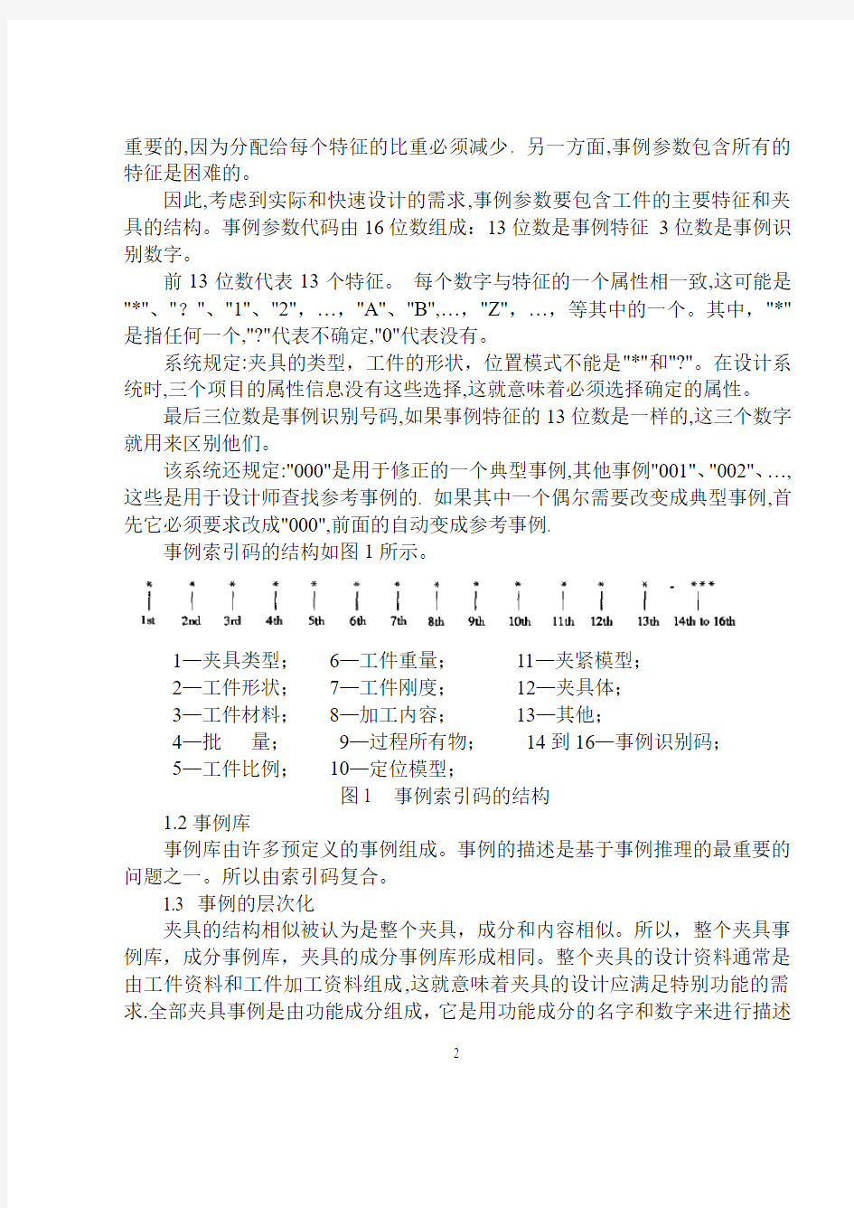
事例索引码的结构如图1所示。
1—夹具类型;6—工件重量;11—夹紧模型;
2—工件形状;7—工件刚度;12—夹具体;
3—工件材料;8—加工内容;13—其他;
4—批量;9—过程所有物;14到16—事例识别码;
5—工件比例;10—定位模型;
图1 事例索引码的结构
1.2事例库
事例库由许多预定义的事例组成。事例的描述是基于事例推理的最重要的问题之一。所以由索引码复合。
1.3 事例的层次化
夹具的结构相似被认为是整个夹具,成分和内容相似。所以,整个夹具事例库,成分事例库,夹具的成分事例库形成相同。整个夹具的设计资料通常是由工件资料和工件加工资料组成,这就意味着夹具的设计应满足特别功能的需求.全部夹具事例是由功能成分组成,它是用功能成分的名字和数字来进行描述
的。成分事例代表成员(成分功能和其他结构成分,主要驱动参数,数字,和它们的约束关系)。成分事例(夹具的最低层)是功能成分和和其他成分的结构。在现代夹具设计中有很多参数化准件和普通非标准件。所以成分事例图书馆应记录特殊参数和保持它们的方法。
2事例修改的策略
在基于事例的夹具设计中,最重要的是相似点的修改,这样能有助于获得最相似的事例,以及缩短适应时间。根据夹具设计的需求,事例修改的策略使最接近的事例方法和知识指导结合起来。首先在深度上查找,然后在宽度上;知识指导策略意味着在来自客观事物根源的知识规则上查找,这就要首先查找固定类型,然后查找工件的形状,第三查找定位方法。例如,如果事例索引码包括夹具类型的磨削夹具,就只查找所有的磨削夹具,然后查找工件形状的盒子,第三查找一个平面两个销的定位方法。如果没有合适的,就查找深度标点,然后回到最上层,然后再找所有与宽度相关的事例。
修改方法:
1)根据夹具事例库的事例索引信息,查找有关事例库。
2)将事例索引码与事例库的每个事例码匹配,然后计算相似尺寸的价值。
3)整理相似尺寸的次序,最大的架子是最类似的事例。
两个事例之间的相似点是基于两个事例特征之间的相似点。相似点尺寸的计算依靠特征的类型。相似点的价值可以通过数字化的价值来计算,例如比较重量分别是50kg 和20kg的工件。非数字化的价值也能计算,例如,现在前13位索引码都是非数字化的价值。一个夹具的相似尺寸的计算公式如下:
其中S表示通用夹具的相似尺寸,n表示索引特性数,表示每个特性的重量,
表示事例库中特性和相关夹具的特性的相似尺寸。同时,
,数值计算如下:
其中表示第i个特征的索引特性值,表示事例库中第j个事例的第i个特
征的特性值。
所以有两种方法选择相似夹具。一个方法是建立数值。如果通用事例的相似尺寸值比给定的数值小,这些事例就不能选来作相似事例。事例库最初建立的时候,只有一些事例,数值可以建小一点。如果有大量的相似事例,数值就应该建的大一些。另外一个方法是只建立相似事例的数字(例如10),这是类型单里相似尺寸的最大值。
3 事例的修改和存储
3.1事例的修改
夹具设计中相似事例的修改包括以下三个阶段:
1)成分的替代
2)保持形式不变,调整成分的特性
3)模型重新设计
如果夹具的成分是普通的物品,它们能通过使用工具被修改,代替以及删除,这些已经被设计好了。
3.2事例的存储
在将一个新的事例保存到事例库之前,设计者必须考虑保存是否有价值。如果这个事例不能增加系统的知识,就没有必要把它保存到事例库里。如果它有价值的话,设计者在保存之前必须分析一下,看看这个事例是否作为标准事例或参考事例被存储了。一个标准事例是一个描述同族事例主要特征的标准。一个同族事例是有事例库中索引码前13位相同而最后三位不同的那些事例组成的。一个标准事例的最后三位通常是“000”。一个参考事例属于同族标准事例,
最后三位用不同数字区分。
从被解释的概念中,可采用以下方法:
1)如果一个新的事例和任何一个存在的事例族一致,和一个存在的标准事例的前13位数相同,那么这个事例就不能存储因为已经这种标准事例了。或者只能作为一个参考事例保存(最后三位不是“000”,而且和其它的不一样)在事例库中。
2)如果一个新的事例和任何一个存在的事例族一致,并且被认为代替这个事例族要比以前的标准事例好,那么这个标准事例就被这个新的事例代替,以前的标准事例作为一个参考事例保存。
3)如果一个新的事例和任何一个存在的事例族不一致,一个新的事例族将会自动产生,并作为标准事例保存到事例库中。
4夹具设计中基于事例推理的过程
根据夹具设计的特性,夹具设计的基本信息,例如夹具的名字,零件,生产和设计者等等,必须先输入。然后,输入或设计工件的模型。输入有关工件的细节信息,建立事例索引码,然后CBR开始依靠相似尺寸查找相似事例,选出最相似的事例。如果需要的话,事例要满足通用性设计,再存储到事例库中。程序流程图如图2所示
图2 基于事例推理的夹具设计流程图
5基于事例推理的夹具设计说明
这是一个工件如图3所示。材料是45钢,底座,形状为块状,生产批量为中批等。需要设计成一个用来旋转孔的旋转夹具。
图3 需要设计夹具的一个工件
(最大尺寸80mmx49mmx22mm)
工件的特征值,属性值,事例索引码和重量在表1中列出。
表1 工件的事例索引码和重量
特征名称特性值索引码重量
夹具类型车床夹具 1 100
工件形状块状9 90
工件材料中碳钢 3 70
批量中批 2 60
工件比例小 5 60
工件重量轻 5 60
工件刚度硬度强 1 60
加工内容孔 3 80
程序要求完成加工 3 70
定位方法三个平面 1 100
夹紧方法不确定?90
夹具体复合 4 80
其他没有0 60
通过查找和计算相似点,最相似的事例的事例索引码是19325513321402000,细节信息在表2中列出。
表2 最相似事例的事例索引码
特征名称特性值索引码
夹具类型车床夹具 1
工件形状块状9
工件材料中碳钢 3
批量中批 2
工件比例小 5
工件重量轻 5
工件刚度硬度强 1
加工内容孔 3
程序要求完成加工 3
定位方法三个平面 1
夹紧方法不确定?
夹具体复合 4
其他没有0
相似点的计算如下:
所以夹具的相似尺寸值是0.806,这是在事例库中用于设计的最相似的事例,最相似的事例的结构如图4所示
图4 最相似的夹具
当成分替代,修改定位模型和夹紧模型,以及调节相关尺寸之后,新的夹具被设计出来,图形如图6所示
图5 需要设计的新夹具
因为在事例库中没有相似夹具,新夹具被储存到事例库中。事例索引码是19325523311402000。
6 结论
基于事例推理,作为一个问题解决的方法,是一个比模仿人类思想的专业系统更有效的方法,已经在很多难获取知识的领域里得到发展。基于事例推理的优点如下:它和人类的思想很相似;一个事例库通过保存新事例获得自学能力,它比有惯例库更快更容易,它可以更好的传递和解释新的知识,这和惯例库有
很大的不同。基于事例推理中提出的一个夹具设计的框架已经被实行了,使用的是支持基础数据的VC++,UG电脑绘图软件。这个框架也已经和普通成分库和典型夹具库结合起来。这个发展的标准系统,用于航空项目,帮助夹具设计者提高设计效率和重新使用先前的设计资源。
附录2 英文原文
Application and development
Of case based reasoning in fixture design
Abstract: Based on the case based designing (CBD) methodology, the fixture similarity is in two respects: the function and the structure information. Then, the computer aided fixture design system is created on case based reasoning (CBR),in which the attributes of the main features of workpiece and structure of fixture as case index code are designed for the retrieve of the similar cases, and the structure and hierarchical relation of case library are set up for store. Meanwhile, the algorithm based on the knowledge guided in the retrieve of the similar cases, the strategy of case adapt at ion and case storage in which the case ident if cat ion number is used to distinguish from similar cases are presented. The application of the system in some projects improves the design efficiency and gets a good result .
Keywords: case based reasoning ;fixture design; computer aided design(CAD)
Fixtures are devices that serve as the purpose of holding the workpiece securely and accurately, and maintaining a consistent relationship with respect to the tools while machining. Because the fixture structure depends on the feature of the product and the status of the process planning in the enterprise, its design is the bottleneck during manufacturing, which restrains to improve the efficiency and leadtime. And fixture design is a complicated process, based on experience that
needs comprehensive qualitative knowledge about a number of design issues including workpiece configuration, manufacturing processes involved, and machining environment. This is also a very time consuming work when using traditional CAD tools (such as Unigraphics, CATIA or Pro/E), which are good at performing detailed design tasks, but provide few benefits for taking advantage of the previous design experience and resources, which are precisely the key factors in improving the efficiency. The methodology of case based reasoning (CBR) adapts the solution of a previously solved case to build a solution for a new problem with the following four steps: retrieve, reuse, revise, and retain [1]. This is a more useful method than the use of an expert system to simulate human thought because proposing a similar case and applying a few modifications seems to be self explanatory and more intuitive to humans .So various case based design support tools have been developed for numerous areas[2-4], such as in injection molding and design, architectural design, die casting die design, process planning, and also in fixture design. Sun used six digitals to compose the index code that included workpiece shape, machine portion, bushing, the 1st locating device, the 2nd locating device and clamping device[5]. But the system cannot be used for other fixture types except for drill fixtures, and cannot solve the problem of storage of the same index code that needs to be retained, which is very important in CBR[6].
1 Construction of a Case Index and Case Library
1.1 Case index
The case index should be composed of all features of the workpiece, which
are distinguished from different fixtures. Using all of them would make the operation in convenient. Because the forms of the parts are diverse, and the technology requirements of manufacture in the enterprise also develop continuously, lots of features used as the case index will make the search rate slow, and the main feature unimportant, for the reason that the relative weight which is allotted to every feature must diminish. And on the other hand, it is hard to include all the features in the case index.
Therefore, considering the practicality and the demand of rapid design, the case index includes both the major feature of the workpiece and the structure of fixture. The case index code is made up of 16 digits: 13 digits for case features and 3 digits for case identification number.
The first 13 digits represent 13 features. Each digit is corresponding to an attribute of the feature, which may be one of“*”, “?”, “1”, “2”,…,“A”,“B”,…,“Z”,…, etc. In which, “*”means anyone, “?”uncertain, “0”nothing.
The system rules: fixture type, workpiece shape, locating model cannot be “*”or“?”. When the system is designed, the attribute information of the three items does not have these options, which means the certain attribute must be selected.
The last three digits are the case identification number, which means the 13 digits of the case feature are the same, and the number of these three digits is used for distinguishing them.
The system also rules: “000”is a prototype case, which is used for retrieval,
and other cases are “001”,“002”,…,which are used for reference cases to be searched by designers. If occasionally one of them needs to be changed as the prototype case, first it must be required to apply to change the one to “000”, and the former is changed to referential case automatically.
The construction of the case index code is shown in Fig.1.
1.2 Case library
The case library consists of lots of predefined cases. Case representation is one of the most important issues in case based reasoning. So compounding with the index code,.
1.3 Hierarchical form of Case
The structure similarity of the fixture is represented as the whole fixture similarity, components similarity and component similarity. So the whole fixture case library, components case library, component case library of fixture are formed correspondingly. Usually design information of the whole fixture is composed of workpiece information and workpiece procedure information, which represent the fixture satisfying the specifically designing function demand. The whole fixture case is made up of function components, which are described by the function
components’names and numbers. The components case represents the members. (function component and other structure components,main driven parameter, the number, and their constrain relations.) The component case (the lowest layer of the fixture) is the structure of function component and other components. In the modern fixture design there are lots of parametric standard parts and common non standard parts. So the component case library should record the specification parameter and the way in which it keeps them.
2 Strategy of Case Retrieval
In the case based design of fixtures ,the most important thing is the retrieval of the similarity, which can help to obtain the most similar case, and to cut down the time of adaptation. According to the requirement of fixture design, the strategy of case retrieval combines the way of the nearest neighbor and knowledge guided. That is, first search on depth, then on breadth; the knowledge guided strategy means to search on the knowledge rule from root to the object, which is firstly searched by the fixture type, then by the shape of the workpiece, thirdly by the locating method. For example, if the case index code includes the milling fixture of fixture type, the search is just for all milling fixtures, then for box of workpiece shape, the third for 1plane+ 2pine of locating method. If there is no match of it, then the search stops on depth, and returns to the upper layer, and retrieves all the relative cases on breadth.
Retrieval algorithms:
1)According to the case index information of fixture case library, search the relevant case library;
2)Match the case index code with the code of each case of the case library, and calculate the value of the similarity measure;
3)Sort the order of similarity measure, the biggest value, which is the most analogical case.
Similarity between two cases is based on the similarity between the two cases. features. The calculation of similarity measure depends on the type of the feature. The value of similarity can be calculated for numerical values, for example, compareWorkpiece with the weight of 50kg and 20kg. The value can also be calculated between non numerical values, for example, now the first 13 digits index code is all non numerical values. The similarity measure of a fixture is calculated as follows:
where S is the similarity measure of current fixture, n is the number of the
index feature, is the weight of each feature, is the similarity
measure of the attribute of the i2th feature with the attribute of relative
feature of the j-th case in the case library. At the same time, , the value counts as follows:
.
Where is the value of the index attribute of the i-th feature, and is the value of attribute of the relative i-th feature of the j-th case in case library.
So there are two methods to select the analogical fixture. One is to set the value. If the values of similarity measure of current cases were less than a given value, those cases would not be selected as analogical cases. When the case library is initially set up, and there are only a few cases, the value can be set smaller. If there are lots of analogical cases, the value should get larger. The other is just to set the number of the analogical cases (such as10), which is the largest value of similarity measure from the sorted order.
3 Case adaptation and Case Storage
3.1 Case adaptation
The modification of the analogical case in the fixture design includes the following three cases:
1) The substitution of components and the component;
2) Adjusting the dimension of components and the component while the form
remains;
3) The redesign of the model.
If the components and component of the fixture are common objects, they can be edited, substituted and deleted with tools, which have been designed.
3.2 Case storage
Before saving a new fixture case in the case library, the designer must consider whether the saving is valuable. If the case does not increase the knowledge of the system, it is not necessary to store it in the case library. If it is valuable, then the designer must analyze it before saving it to see whether the case is stored as a prototype case or as reference case. A prototype case is a representation that can describe the main features of a case family. A case family consists of those cases whose index codes have the same first 13 digits and different last three digits in the case library. The last three digits of a prototype case are always “000”. A reference case belongs to the same family as the prototype case and is distinguished by the different last three digits.
From the concept that has been explained, the following strategies are adopted:
1) If a new case matches any existing case family, it has the same first 13 digits as an existing prototype case, so the case is not saved because it is represented well by the prototype case. Or is just saved as a reference case (the last 3 digits are not “000”, and not the same with others) in the case library.
2) If a new case matches any existing case family and is thought to be better at representing this case family than the previous prototype case, then the prototype
case is substituted by this new case, and the previous prototype case is saved as a reference case.
3) If a new case does not match any existing case family, a new case family will be generated automatically and the case is stored as the prototype case in the case library.
4 Process of CBR in Fixture Design
According to the characteristics of fixture design, the basic information of the fixture design such as the name of fixture, part, product and the designer, etc. must be input first. Then the fixture file is set up automatically, in which all components of the fixture are put together. Then the model of the workpiece is input or designed. The detailed information about the workpiece is input, the case index code is set up, and then the CBR begins to search the analogical cases, relying on the similarity measure, and the most analogical case is selected out. If needed, the case is adapted to satisfy the current design, and restored into the case library. The flowchart of the process is shown in Fig.3.
5 Illustrating for Fixture Design by CBR
This is a workpiece (seeFig.4). Its material is 45# steel. Its name is seat. Its shape is block, and the product batch size is middle, etc. A fixture is turning fixture that serves to turn the hole, which needs to be designed.
The value of feature, attribute, case index code and weight of the workpiece
is show n in Tab.2.
Through searching, and calculating the similarity, the case index code of the most similar case is 19325513321402000, and the detailed information is show n in Tab. 3.
The similarity is calculated as follows:
毕业论文(设计) 外文翻译 题目:机械加工介绍
机械加工介绍 1.车床 车床主要是为了进行车外圆、车端面和镗孔等项工作而设计的机床。车削很少在其他种类的机床上进行,而且任何一种其他机床都不能像车床那样方便地进行车削加工。由于车床还可以用来钻孔和铰孔,车床的多功能性可以使工件在一次安装中完成几种加工。因此,在生产中使用的各种车床比任何其他种类的机床都多。 车床的基本部件有:床身、主轴箱组件、尾座组件、溜板组件、丝杠和光杠。 床身是车床的基础件。它能常是由经过充分正火或时效处理的灰铸铁或者球墨铁制成。它是一个坚固的刚性框架,所有其他基本部件都安装在床身上。通常在床身上有内外两组平行的导轨。有些制造厂对全部四条导轨都采用导轨尖朝上的三角形导轨(即山形导轨),而有的制造厂则在一组中或者两组中都采用一个三角形导轨和一个矩形导轨。导轨要经过精密加工以保证其直线度精度。为了抵抗磨损和擦伤,大多数现代机床的导轨是经过表面淬硬的,但是在操作时还应该小心,以避免损伤导轨。导轨上的任何误差,常常意味着整个机床的精度遭到破坏。 主轴箱安装在内侧导轨的固定位置上,一般在床身的左端。它提供动力,并可使工件在各种速度下回转。它基本上由一个安装在精密轴承中的空心主轴和一系列变速齿轮(类似于卡车变速箱)所组成。通过变速齿轮,主轴可以在许多种转速下旋转。大多数车床有8~12种转速,一般按等比级数排列。而且在现代机床上只需扳动2~4个手柄,就能得到全部转速。一种正在不断增长的趋势是通过电气的或者机械的装置进行无级变速。 由于机床的精度在很大程度上取决于主轴,因此,主轴的结构尺寸较大,通常安装在预紧后的重型圆锥滚子轴承或球轴承中。主轴中有一个贯穿全长的通孔,长棒料可以通过该孔送料。主轴孔的大小是车床的一个重要尺寸,因此当工件必须通过主轴孔供料时,它确定了能够加工的棒料毛坯的最大尺寸。 尾座组件主要由三部分组成。底板与床身的内侧导轨配合,并可以在导轨上作纵向移动。底板上有一个可以使整个尾座组件夹紧在任意位置上的装置。尾座体安装在底板上,可以沿某种类型的键槽在底板上横向移动,使尾座能与主轴箱中的主轴对正。尾座的第三个组成部分是尾座套筒。它是一个直径通常大约在51~76mm之间的钢制空心圆柱体。
On the vehicle sideslip angle estimation through neural networks: Numerical and experimental results. S. Melzi,E. Sabbioni Mechanical Systems and Signal Processing 25 (2011):14~28 电脑估计车辆侧滑角的数值和实验结果 S.梅尔兹,E.赛博毕宁 机械系统和信号处理2011年第25期:14~28
摘要 将稳定控制系统应用于差动制动内/外轮胎是现在对客车车辆的标准(电子稳定系统ESP、直接偏航力矩控制DYC)。这些系统假设将两个偏航率(通常是衡量板)和侧滑角作为控制变量。不幸的是后者的具体数值只有通过非常昂贵却不适合用于普通车辆的设备才可以实现直接被测量,因此只能估计其数值。几个州的观察家最终将适应参数的参考车辆模型作为开发的目的。然而侧滑角的估计还是一个悬而未决的问题。为了避免有关参考模型参数识别/适应的问题,本文提出了分层神经网络方法估算侧滑角。横向加速度、偏航角速率、速度和引导角,都可以作为普通传感器的输入值。人脑中的神经网络的设计和定义的策略构成训练集通过数值模拟与七分布式光纤传感器的车辆模型都已经获得了。在各种路面上神经网络性能和稳定已经通过处理实验数据获得和相应的车辆和提到几个处理演习(一步引导、电源、双车道变化等)得以证实。结果通常显示估计和测量的侧滑角之间有良好的一致性。 1 介绍 稳定控制系统可以防止车辆的旋转和漂移。实际上,在轮胎和道路之间的物理极限的附着力下驾驶汽车是一个极其困难的任务。通常大部分司机不能处理这种情况和失去控制的车辆。最近,为了提高车辆安全,稳定控制系统(ESP[1,2]; DYC[3,4])介绍了通过将差动制动/驱动扭矩应用到内/外轮胎来试图控制偏航力矩的方法。 横摆力矩控制系统(DYC)是基于偏航角速率反馈进行控制的。在这种情况下,控制系统使车辆处于由司机转向输入和车辆速度控制的期望的偏航率[3,4]。然而为了确保稳定,防止特别是在低摩擦路面上的车辆侧滑角变得太大是必要的[1,2]。事实上由于非线性回旋力和轮胎滑移角之间的关系,转向角的变化几乎不改变偏航力矩。因此两个偏航率和侧滑角的实现需要一个有效的稳定控制系统[1,2]。不幸的是,能直接测量的侧滑角只能用特殊设备(光学传感器或GPS惯性传感器的组合),现在这种设备非常昂贵,不适合在普通汽车上实现。因此, 必须在实时测量的基础上进行侧滑角估计,具体是测量横向/纵向加速度、角速度、引导角度和车轮角速度来估计车辆速度。 在主要是基于状态观测器/卡尔曼滤波器(5、6)的文学资料里, 提出了几个侧滑角估计策略。因为国家观察员都基于一个参考车辆模型,他们只有准确已知模型参数的情况下,才可以提供一个令人满意的估计。根据这种观点,轮胎特性尤其关键取决于附着条件、温度、磨损等特点。 轮胎转弯刚度的提出就是为了克服这些困难,适应观察员能够提供一个同步估计的侧滑角和附着条件[7,8]。这种方法的弊端是一个更复杂的布局的估计量导致需要很高的计算工作量。 另一种方法可由代表神经网络由于其承受能力模型非线性系统,这样不需要一个参
附录A Lathe fixture design and analysis Ma Feiyue (School of Mechanical Engineering, Hefei, Anhui Hefei 230022, China) Abstract: From the start the main types of lathe fixture, fixture on the flower disc and angle iron clamp lathe was introduced, and on the basis of analysis of a lathe fixture design points. Keywords: lathe fixture; design; points Lathe for machining parts on the rotating surface, such as the outer cylinder, inner cylinder and so on. Parts in the processing, the fixture can be installed in the lathe with rotary machine with main primary uranium movement. However, in order to expand the use of lathe, the work piece can also be installed in the lathe of the pallet, tool mounted on the spindle. THE MAIN TYPES OF LATHE FIXTURE Installed on the lathe spindle on the lathe fixture
Lathes Lathes are machine tools designed primarily to do turning, facing and boring, Very little turning is done on other types of machine tools, and none can do it with equal facility. Because lathes also can do drilling and reaming, their versatility permits several operations to be done with a single setup of the work piece. Consequently, more lathes of various types are used in manufacturing than any other machine tool. The essential components of a lathe are the bed, headstock assembly, tailstock assembly, and the leads crew and feed rod. The bed is the backbone of a lathe. It usually is made of well normalized or aged gray or nodular cast iron and provides s heavy, rigid frame on which all the other basic components are mounted. Two sets of parallel, longitudinal ways, inner and outer, are contained on the bed, usually on the upper side. Some makers use an inverted V-shape for all four ways, whereas others utilize one inverted V and one flat way in one or both sets, They are precision-machined to assure accuracy of alignment. On most modern lathes the way are surface-hardened to resist wear and abrasion, but precaution should be taken in operating a lathe to assure that the ways are not damaged. Any inaccuracy in them usually means that the accuracy of the entire lathe is destroyed. The headstock is mounted in a foxed position on the inner ways, usually at the left end of the bed. It provides a powered means of rotating the word at various speeds . Essentially, it consists of a hollow spindle, mounted in accurate bearings, and a set of transmission gears-similar to a truck transmission—through which the spindle can be rotated at a number of speeds. Most lathes provide from 8 to 18 speeds, usually in a geometric ratio, and on modern lathes all the speeds can be obtained merely by moving from two to four levers. An increasing trend is to provide a continuously variable speed range through electrical or mechanical drives. Because the accuracy of a lathe is greatly dependent on the spindle, it is of heavy construction and mounted in heavy bearings, usually preloaded tapered roller or ball types. The spindle has a hole extending through its length, through which long bar stock can be fed. The size of maximum size of bar stock that can be machined when the material must be fed through spindle. The tailsticd assembly consists, essentially, of three parts. A lower casting fits on the inner ways of the bed and can slide longitudinally thereon, with a means for clamping the entire assembly in any desired location, An upper casting fits on the lower one and can be moved transversely upon it, on some type of keyed ways, to permit aligning the assembly is the tailstock quill. This is a hollow steel cylinder, usually about 51 to 76mm(2to 3 inches) in diameter, that can be moved several inches longitudinally in and out of the upper casting by means of a hand wheel and screw. The size of a lathe is designated by two dimensions. The first is known as the swing. This is the maximum diameter of work that can be rotated on a lathe. It is approximately twice the distance between the line connecting the lathe centers and the nearest point on the ways, The second size dimension is the maximum distance between centers. The swing thus indicates the maximum work piece diameter that can be turned in the lathe, while the distance between centers indicates the maximum length of work piece that can be mounted between centers. Engine lathes are the type most frequently used in manufacturing. They are heavy-duty machine tools with all the components described previously and have power drive for all tool movements except on the compound rest. They commonly range in size from 305 to 610 mm(12 to 24 inches)swing and from 610 to 1219 mm(24 to 48 inches) center distances, but swings up to 1270 mm(50 inches) and center distances up
外文翻译 通常,应变计应用在两个方面:在机械和结构的实验力分析中和应用力,扭矩,压力,流量以及加速度传感器结构中。非粘贴丝式应变计通常是当作专门的转换器来使用,其结构是使用一些有预载荷的电阻丝连接成惠斯登电桥,如图4.11: 在最初的预载荷中,四根金属丝的应变和电阻在理论上是相等的,它们组成一个平衡电桥,并且e0 = 0 (参考第10章电桥电路特性)。输入端一个小的位移(满量程≈0.04 mm)将会使两根金属丝的拉力增大而使另外两根的拉力减小(假设金属丝不会变松弛),引起电阻阻值的变化,电桥失衡,输出电压与输入位移成比例。金属丝可以由砷镍、镍铬和铁镍等多种合金制造,直径约为0.03 mm,可以承受的最大应力仅为0.002 N,灵敏系数为2到4,每个桥臂的电阻为120Ω到1000Ω, 最大激励电压5到10V,满量程输出典型值为20到50mV。 粘结丝式应变计(现在主要被粘贴箔式结构的应变计取代)应用于应力分析和作为转换器。具有很细丝式敏感栅粘贴在待测试件表面,来感受应变。金属丝被埋入矩形的粘合剂中,不能弯曲从而如实地反映待测试件的压缩和拉伸应力。因为金属丝的材料和尺寸与那些非粘贴应变计相似,所以灵敏度和电阻具有了可比性。 粘贴箔式应变计采用与丝式应变计相同或类似的材料,现在主要用于多用途力分析任务及多种传感器中。 其感应元件是利用光腐蚀工艺加工成厚度小于0.0002的薄片,当其形状改变时,它具有很大的灵活性。如图4.12: 例如,这三个线形敏感栅应变计被设计成端部宽大的形状。这种局部的增大将会减小横向灵敏度,以及在测量应变沿敏感栅单元的长度方向的分量时产生的干扰输入信号。在丝式应变计中,这种端部形状也应用在纵向单元的连接处,以便增加横向抗干扰能力。并且在制造过程中也非常方便在图4.12上的全部四个应变计上焊接焊盘。
毕业设计 外文翻译 题目曲轴的加工工艺及夹具设计学院航海学院 专业轮机工程 学生佟宝诚 学号 10960123 指导教师彭中波 重庆交通大学 2014年
Proceedings of IMECE2008 2008 ASME International Mechanical Engineering Congress and Exposition October 31-November 6, 2008, Boston, Massachusetts, USA IMECE2008-67447 MULTI-OBJECTIVE SYSTEM OPTIMIZATION OF ENGINE CRANKSHAFTS USING AN INTEGRATION APPROACH Albert Albers/IPEK Institute of Product Development University of Karlsruhe Germany Noel Leon/CIDyT Center for Innovation andDesign Monterrey Institute of Technology,Mexico Humberto Aguayo/CIDyT Center forInnovation and Design, Monterrey Institute ofTechnology, Mexico Thomas Maier/IPEK Institute of Product Development University of Karlsruhe Germany ABSTRACT The ever increasing computer capabilities allow faster analysis in the field of Computer Aided Design and Engineering (CAD & CAE). CAD and CAE systems are currently used in Parametric and Structural Optimization to find optimal topologies and shapes of given parts under certain conditions. This paper describes a general strategy to optimize the balance of a crankshaft, using CAD and CAE software integrated with Genetic Algorithms (GAs) via programming in Java. An introduction to the groundings of this strategy is made among different tools used for its implementation. The analyzed crankshaft is modeled in commercial parametric 3D CAD software. CAD is used for evaluating the fitness function (the balance) and to make geometric modifications. CAE is used for evaluating dynamic restrictions (the eigenfrequencies). A Java interface is programmed to link the CAD model to the CAE software and to the genetic algorithms. In order to make geometry modifications to
毕业设计(论文)外文资料翻译 系部: 专业: 姓名: 学号: 外文出处:English For Electromechanical (用外文写) Engineering 附件:1.外文资料翻译译文;2.外文原文。 指导教师评语: 此翻译文章简单介绍了各机床的加工原理,并详细介绍了各机床的构造,并对方各机床的加工方法法进行了详细的描述, 翻译用词比较准确,文笔也较为通顺,为在以后工作中接触英 文资料打下了基础。 签名: 年月日注:请将该封面与附件装订成册。
附件1:外文资料翻译译文 机床 机床是用于切削金属的机器。工业上使用的机床要数车床、钻床和铣床最为重要。其它类型的金属切削机床在金属切削加工方面不及这三种机床应用广泛。 车床通常被称为所有类型机床的始祖。为了进行车削,当工件旋转经过刀具时,车床用一把单刃刀具切除金属。用车削可以加工各种圆柱型的工件,如:轴、齿轮坯、皮带轮和丝杠轴。镗削加工可以用来扩大和精加工定位精度很高的孔。 钻削是由旋转的钻头完成的。大多数金属的钻削由麻花钻来完成。用来进行钻削加工的机床称为钻床。铰孔和攻螺纹也归类为钻削过程。铰孔是从已经钻好的孔上再切除少量的金属。 攻螺纹是在内孔上加工出螺纹,以使螺钉或螺栓旋进孔内。 铣削由旋转的、多切削刃的铣刀来完成。铣刀有多种类型和尺寸。有些铣刀只有两个切削刃,而有些则有多达三十或更多的切削刃。铣刀根据使用的刀具不同能加工平面、斜面、沟槽、齿轮轮齿和其它外形轮廓。 牛头刨床和龙门刨床用单刃刀具来加工平面。用牛头刨床进行加工时,刀具在机床上往复运动,而工件朝向刀具自动进给。在用龙门刨床进行加工时,工件安装在工作台上,工作台往复经过刀具而切除金属。工作台每完成一个行程刀具自动向工件进给一个小的进给量。 磨削利用磨粒来完成切削工作。根据加工要求,磨削可分为精密磨削和非精密磨削。精密磨削用于公差小和非常光洁的表面,非精密磨削用于在精度要求不高的地方切除多余的金属。 车床 车床是用来从圆形工件表面切除金属的机床,工件安装在车床的两个顶尖之间,并绕顶尖轴线旋转。车削工件时,车刀沿着工件的旋转轴线平行移动或与工件的旋转轴线成一斜角移动,将工件表面的金属切除。车刀的这种位移称为进给。车
高精度稳压直流电源 文摘:目前对于可调式直流电源的设计和应用现在有很多微妙的,多种多样的,有趣的问题。探讨这些问题(特别是和中发电机组有关),重点是在电路的经济适用性上,而不是要达到最好的性能。当然,对那些精密程度要求很高的除外。讨论的问题包括温度系数,短期漂移,热漂移,瞬态响应变性遥感和开关preregualtor型机组及和它的性能特点有关的的一些科目。 介绍 从商业的角度来看供电领域可以得到这样一个事实,在相对较低的成本下就可以可以获得标准类型的0.01%供电调节。大部分的供电用户并不需要这么高的规格,但是供应商不会为了减少客户这么一点的费用而把0.1%改成0.01%。并且电力供应的性能还包括其他一些因素,比如说线路和负载调解率。本文将讨论关于温度系数、短期漂移、热漂移,和瞬态的一些内容。 目前中等功率直流电源通常采用预稳压来提高功率/体积比和成本,但是只有某些电力供应采用这样的做法。这种技术的优缺点还有待观察。 温度系数 十年以前,大多数的商业电力供应为规定的0.25%到1%。这里将气体二极管的温度系数定位百分之0.01[1]。因此,人们往往会忽视TC(温度系数)是比规定的要小的。现在参考的TC往往比规定的要大的多。为了费用的减少,后者会有很大的提高,但是这并不是真正的TC。因此,如果成本要保持在一个低的水平,可以采用TC非常低的齐纳二极管,安装上差动放大电路,还要仔细的分析低TC绕线电阻器。 如图1所示,一个典型的放大器的第一阶段,其中CR1是参考齐纳二极管,R是输出电位调节器。
图1 电源输入级 图2 等效的齐纳参考电路 假设该阶段的输出是e3,提供额外的差分放大器,在稳定状态下e3为零,任何参数的变化都会引起输出的漂移;对于其他阶段来说也是一样的,其影响是减少了以前所有阶段的增益。因此,其他阶段的影响将被忽略。以下讨论的内容涵盖了对于TC整体的无论是主要的还是次要的影响。 R3的影响 CR1-R3分支的等效的电路如图2所示,将齐纳替换成了它的等效电压源E'和内部阻抗R2。对于高增益调节器,其中R3的变化对差分放大器的输入来说可以忽略不计,所以前后的变化由R3决定。 如果进一步假定IB << Iz;从(1)可以得到 同时,
2604130359 CNC Cutting Technology Review Numerical control high speed cutting technology (High Speed Machining, HSM, or High Speed Cutting, HSC), is one of the advanced manufacturing technology to improve the machining efficiency and quality, the study of related technology has become an important research direction of advanced manufacturing technology at home and abroad. China is a big manufacturing country, in the world of industry transfer to accept the front instead of back-end of the transfer, to master the core technology of advanced manufacturing, or in a new round of international industrial structure adjustment, our country manufacturing industry will further behind. Imminent research on the theory and application of advanced technology. 1, high-speed CNC machining meaning High speed cutting theory put forward by the German physicist Carl.J.Salomon in the last century and early thirty's. He concluded by a lot of experiments: in the normal range of cutting speed, cutting speed if the increase, will cause the cutting temperature rise, exacerbating the wear of cutting tool; however, when the cutting speed is increased to a certain value, as long as more than the inflection point, with the increase of the cutting speed, cutting temperature can not rise, but will decline, so as long as the cutting speed is high enough, it can be solved very well in high cutting temperature caused by tool wear is not conducive to the cutting problem, obtained good processing efficiency. With the development of manufacturing industry, this theory is gradually paid more attention to, and attracted a lot of attention, on the basis of this theory has gradually formed the field of high-speed cutting technology of NC, relatively early research on NC High-speed Machining Technology in developed countries, through the theoretical basis of the research, basic research and applied research and development application, at present applications have entered the substantive stage in some areas. The high-speed cutting processing category, generally have the following several kinds of classification methods, one is to see that cutting speed, cutting speed over conventional cutting speed is 5-10 times of high speed cutting. Also has the scholar to spindle speed as the definition of high-speed processing standards, that the spindle speed is higher than that of 8000r\/min for high speed machining. And from the machine tool spindle design point of view, with the product of DN diameter of spindle and spindle speed, if the value of DN to (5~2000) * 105mm.r\/min, is considered to be of high speed machining. In practice, different processing methods, different materials, high speed cutting speed corresponding to different. Is generally believed that the turning speed of (700~7000) m\/min, milling speed reaches m\/min (300~6000), that is in the high-speed cutting. In addition, from the practical considerations, high-speed machining concept not only contains the high speed cutting process, integration and optimization also contains the process of cutting, is a
机床加工外文翻译参考文献(文档含中英文对照即英文原文和中文翻译) 基本加工工序和切削技术 基本加工的操作 机床是从早期的埃及人的脚踏动力车和约翰·威尔金森的镗床发展而来的。它们为工件和刀具提供刚性支撑并可以精确控制它们的相对位置和相对速度。基本上讲,金属切削是指一个磨尖的锲形工具从有韧性的工件表面上去除一条很窄的金属。切屑是被废弃的产品,与其它工件相比切屑较短,但对于未切削部分的厚度有一定的增加。工件表面的几何形状取决于刀具的形状以及加工操作过程中刀具的路径。 大多数加工工序产生不同几何形状的零件。如果一个粗糙的工件在中心轴上转动并且刀具平行于旋转中心切入工件表面,一个旋转表面就产生了,这种操作称为车削。如果一个空心的管子以同样的方式在内表面加工,这种操作称为镗孔。当均匀地改变直径时便产生了一个圆锥形的外表面,这称为锥度车削。如果刀具接触点以改变半径的方式运动,那么一个外轮廓像球的工件便产生了;或者如果工件足够的短并且支撑是十分刚硬的,那么成型刀具相对于旋转轴正常进给的一个外表面便可产生,短锥形或圆柱形的表面也可形成。
平坦的表面是经常需要的,它们可以由刀具接触点相对于旋转轴的径向车削产生。在刨削时对于较大的工件更容易将刀具固定并将工件置于刀具下面。刀具可以往复地进给。成形面可以通过成型刀具加工产生。 多刃刀具也能使用。使用双刃槽钻钻深度是钻孔直径5-10倍的孔。不管是钻头旋转还是工件旋转,切削刃与工件之间的相对运动是一个重要因数。在铣削时一个带有许多切削刃的旋转刀具与工件接触,工件相对刀具慢慢运动。平的或成形面根据刀具的几何形状和进给方式可能产生。可以产生横向或纵向轴旋转并且可以在任何三个坐标方向上进给。 基本机床 机床通过从塑性材料上去除屑片来产生出具有特别几何形状和精确尺寸的零件。后者是废弃物,是由塑性材料如钢的长而不断的带状物变化而来,从处理的角度来看,那是没有用处的。很容易处理不好由铸铁产生的破裂的屑片。机床执行五种基本的去除金属的过程:车削,刨削,钻孔,铣削。所有其他的去除金属的过程都是由这五个基本程序修改而来的,举例来说,镗孔是内部车削;铰孔,攻丝和扩孔是进一步加工钻过的孔;齿轮加工是基于铣削操作的。抛光和打磨是磨削和去除磨料工序的变形。因此,只有四种基本类型的机床,使用特别可控制几何形状的切削工具1.车床,2.钻床,3.铣床,4.磨床。磨削过程形成了屑片,但磨粒的几何形状是不可控制的。 通过各种加工工序去除材料的数量和速度是巨大的,正如在大型车削加工,或者是极小的如研磨和超精密加工中只有面的高点被除掉。一台机床履行三大职能:1.它支撑工件或夹具和刀具2.它为工件和刀具提供相对运动3.在每一种情况下提供一系列的进给量和一般可达4-32种的速度选择。 加工速度和进给 速度,进给量和切削深度是经济加工的三大变量。其他的量数是攻丝和刀具材料,冷却剂和刀具的几何形状,去除金属的速度和所需要的功率依赖于这些变量。 切削深度,进给量和切削速度是任何一个金属加工工序中必须建立的机械参量。它们都影响去除金属的力,功率和速度。切削速度可以定义为在旋转一周时
A review and analysis of current computer-aided fixture design approaches Iain Boyle, Yiming Rong, David C. Brown Keywords: Computer-aided fixture design Fixture design Fixture planning Fixture verification Setup planning Unit design ABSTRACT A key characteristic of the modern market place is the consumer demand for variety. To respond effectively to this demand, manufacturers need to ensure that their manufacturing practices are sufficiently flexible to allow them to achieve rapid product development. Fixturing, which involves using fixtures to secure work pieces during machining so that they can be transformed into parts that meet required design specifications, is a significant contributing factor towards achieving manufacturing flexibility. To enable flexible fixturing, considerable levels of research effort have been devoted to supporting the process of fixture design through the development of computer-aided fixture design (CAFD) tools and approaches. This paper contains a review of these research efforts. Over seventy-five CAFD tools and approaches are reviewed in terms of the fixture design phases they support and the underlying technology upon which they are based. The primary conclusion of the review is that while significant advances have been made in supporting fixture design, there are primarily two research issues that require further effort. The first of these is that current CAFD research is segmented in nature and there remains a need to provide more cohesive fixture design support. Secondly, a greater focus is required on supporting the detailed design of a fixture’s physical structure. 2010 Elsevier Ltd. All rights reserved. Contents 1. Introduction (2) 2. Fixture design (2) 3. Current CAFD approaches (4) 3.1 Setup planning (4) 3.1.1 Approaches to setup planning (4) 3.2 Fixture planning (4) 3.2.1 Approaches to defining the fixturing requirement (6) 3.2.2 Approaches to non-optimized layout planning (6) 3.2.3 Approaches to layout planning optimization (6) 3.3 Unit design (7) 3.3.1 Approaches to conceptual unit design (7)
中文4285字 附录1 LATHES & MILLING A shop that is equipped with a milling machine and an engine lathe can machine almost any type of product of suitable size. The basic machines that are designed primarily to do turning,facing and boring are called lathes. Very little turning is done on other types of machine tools,and none can do it with equal facility. Because lathe can do boring,facing,drilling,and reaming in addition to turning,their versatility permits several operations to be performed with a single setup of the workpiece. This accounts for the fact that lathes of various types are more widely used in manufacturing than any other machine tool. Lathes in various forms have existed for more than two thousand years. Modern lathes date from about 1797,when Henry Maudsley developed one with a leads crew. It provided controlled,mechanical feed of the tool. This ingenious Englishman also developed a change gear system that could connect the motions of the spindle and leadscrew and thus enable threads to be cut. Lathe Construction.The essential components of a lathe are depicted in the block diagram of picture. These are the bed,headstock assembly,tailstock assembly,carriage assembly,quick-change gearbox,and the leadscrew and feed rod. The bed is the back bone of a lathe. It usually is made of well-normalized or aged gray or nodular cast iron and provides a heavy,rigid frame on which all the other basic components are mounted. Two sets of parallel,longitudinal ways,inner and outer,are contained on the bed,usually on the upper side. Some makers use an inverted V-shape for all four ways,whereas others utilize one inverted V and one flat way in one or both sets. Because several other components are mounted and/or move on the ways they must be made with precision to assure accuracy of alignment. Similarly,proper precaution should betaken in operating a lathe to assure that the ways are not damaged. Any inaccuracy in them usually means that the accuracy of the entire lathe is destroyed. The ways on most modern lathes are surface hardened to