汽车焊接夹具设计中英文对照外文翻译文献
- 格式:doc
- 大小:48.00 KB
- 文档页数:12
汽车焊接夹具设计外文文献翻译(含:英文原文及中文译文)文献出处:Semjon Kim.Design of Automotive Welding Fixtures [J]. Computer-Aided Design, 2013, 3(12):21-32.英文原文Design of Automotive Welding FixturesSemjon Kim1 AbstractAccording to the design theory of car body welding fixture, the welding fixture and welding bus of each station are planned and designed. Then the fixture is modeled and assembled. The number and model of the fixture are determined and the accessibility is judged. Designed to meet the requirements of the welding fixture.Keywords: welded parts; foundation; clamping; position1 IntroductionAssembly and welding fixtures are closely related to the production of high-quality automotive equipment in automotive body assembly and welding lines. Welded fixtures are an important part of the welding process. Assembly and welding fixtures are not only the way to complete the assembly of parts in this process, but also as a test and calibration procedure on the production line to complete the task of testing welding accessories and welding quality. Therefore, the design and manufacture ofwelding fixtures directly affect the production capacity and product quality of the automobile in the welding process. Automotive welding fixtures are an important means of ensuring their manufacturing quality and shortening their manufacturing cycle. Therefore, it is indispensable to correctly understand the key points of welding fixture design, improve and increase the design means and design level of welding fixtures, and improve the adjustment and verification level of fixtures. It is also an auto manufacturing company in the fierce competition. The problem that must be solved to survive.The style of the car is different from that of the car. Therefore, the shape of the welding jig is very different. However, the design, manufacture, and adjustment are common and can be used for reference.2. Structural design of welding fixtureThe structure design of the welding fixture ensures that the clip has good operational convenience and reliable positioning of the fixture. Manufacturers of welding fixtures can also easily integrate adjustments to ensure that the surfaces of the various parts of the structure should allow enough room for adjustments to ensure three-dimensional adjustment. Of course, under the premise of ensuring the accuracy of the welding jig, the structure of the welding jig should be as simple as possible. The fixture design is usually the position of all components on the fixture is determined directly based on the design basis, and ultimately ensure thatthe qualified welding fixture structure is manufactured. According to the working height, the height of the fixture bottom plate can be preliminarily determined, that is, the height of the fixture fixing position. The welding fixture design must first consider the clamping method. There are two types, manual and pneumatic. Manual clamping is generally suitable for small parts, external parts, and small batches of workpieces. For large body parts, planning in the production line, automation High-demand welding fixtures should be pneumatically clamped. Automobile production is generally pneumatically clamped, and manual mass clamping can be used as auxiliary clamping. This can reduce costs accordingly. Some manual clamping products already have standard models and quantities, which can be purchased in the market when needed. For some devices, pneumatic clamping is specified, but if pneumatic clamping is used, the workpiece may be damaged. Therefore, it is possible to manually press the place first to provide a pneumatic clamping force to clamp the workpiece. This is manual-pneumatic. . The fixture clamping system is mounted on a large platform, all of which are fixed in this welding position to ensure that the welding conditions should meet the design dimensions of the workpiece coordinate system positioning fixture, which involves the benchmark.3. Benchmarks of assembly and welding fixtures and their chosen support surfaces3.1 Determination of design basisIn order to ensure that the three-dimensional coordinates of the automatic weldment system are consistent, all welding fixtures must have a common reference in the system. The benchmark is the fixture mounting platform. This is the X, Y coordinate, each specific component is fixed at the corresponding position on the platform, and has a corresponding height. Therefore, the Z coordinate should be coordinated, and a three-dimensional XYZ coordinate system is established. In order to facilitate the installation and measurement of the fixture, the mounting platform must have coordinates for reference. There are usually three types. The structure is as follows:3.1.1 Reference hole methodThere are four reference holes in the design of the installation platform, in which the two directions of the center coordinates of each hole and the coordinates of the four holes constitute two mutually perpendicular lines. This is the collection on the XY plane coordinate system. The establishment of this benchmark is relatively simple and easy to process, but the measurements and benchmarks used at the same time are accurate. Any shape is composed of spatial points. All geometric measurements can be attributed to measurements of spatial points. Accurate spatial coordinate acquisition is therefore the basis for assessing any geometric shape. Reference A coordinated direction formed by oneside near two datums.3.1.2 v-type detection methodIn this method, the mounting platform is divided into two 90-degree ranges. The lines of the two axes make up a plane-mounted platform. The plane is perpendicular to the platform. The surface forms of these two axis grooves XY plane coordinate system.3.1.3 Reference block methodReference Using the side block perpendicular to the 3D XYZ coordinate system, the base of a gage and 3 to 4 blocks can be mounted directly on the platform, or a bearing fixing fixture platform can be added, but the height of the reference plane must be used to control the height , must ensure the same direction. When manufacturing, it is more difficult to adjust the previous two methods of the block, but this kind of measurement is extremely convenient, especially using the CMM measurement. This method requires a relatively low surface mount platform for the reference block, so a larger sized mounting platform should use this method.Each fixture must have a fixed coordinate system. In this coordinate system, its supporting base coordinate dimensions should support the workpiece and the coordinates correspond to the same size. So the choice of bearing surface in the whole welding fixture system 3.2When the bearing surface is selected, the angle between the tangentplane and the mounting platform on the fixed surface of the welding test piece shall not be greater than 15 degrees. The inspection surface should be the same as the welded pipe fittings as much as possible for the convenience of flat surface treatment and adjustment. The surface structure of the bearing should be designed so that the module can be easily handled, and this number can be used for the numerical control of the bearing surface of the product. Of course, designing the vehicle body coordinate point is not necessarily suitable for the bearing surface, especially the NC fixture. This requires the support of the fixture to block the access point S, based on which the digital surface is established. This surface should be consistent with the supported surface. So at this time, it is easier and easier to manufacture the base point S, CNC machining, precision machining and assembly and debugging.3.2 Basic requirements for welding fixtureIn the process of automobile assembly and production, there are certain requirements for the fixture. First, according to the design of the automobile and the requirements of the welding process, the shape, size and precision of the fixture have reached the design requirements and technical requirements. This is a link that can not be ignored, and the first consideration in the design of welding fixture is considered. When assembling, the parts or parts of the assembly should be consistent with the position of the design drawings of the car and tighten with the fixture.At the same time, the position should be adjusted to ensure that the position of the assembly parts is clamped accurately so as to avoid the deformation or movement of the parts during the welding. Therefore, this puts forward higher requirements for welding jig. In order to ensure the smooth process of automobile welding and improve the production efficiency and economic benefit, the workers operate conveniently, reduce the strength of the welder's work, ensure the precision of the automobile assembly and improve the quality of the automobile production. Therefore, when the fixture design is designed, the design structure should be relatively simple, it has good operability, it is relatively easy to make and maintain, and the replacement of fixture parts is more convenient when the fixture parts are damaged, and the cost is relatively economical and reasonable. But the welding fixture must meet the construction technology requirements. When the fixture is welded, the structure of the fixture should be open so that the welding equipment is easy to close to the working position, which reduces the labor intensity of the workers and improves the production efficiency.4. Position the workpieceThe general position of the workpiece surface features is determined relative to the hole or the apparent positioning reference surface. It is commonly used as a locating pin assembly. It is divided into two parts: clamping positioning and fixed positioning. Taking into account thewelding position and all welding equipment, it is not possible to influence the removal of the final weld, but also to allow the welding clamp or torch to reach the welding position. For truly influential positioning pins and the like, consider using movable positioning pins. In order to facilitate the entry and exit of parts, telescopic positioning pins are available. The specific structure can be found in the manual. The installation of welding fixtures should be convenient for construction, and there should be enough space for assembly and welding. It must not affect the welding operation and the welder's observation, and it does not hinder the loading and unloading of the weldment. All positioning elements and clamping mechanisms should be kept at a proper distance from the solder joints or be placed under or on the surface of the weldment. The actuator of the clamping mechanism should be able to flex or index. According to the formation principle, the workpiece is clamped and positioned. Then open the fixture to remove the workpiece. Make sure the fixture does not interfere with opening and closing. In order to reduce the auxiliary time for loading and unloading workpieces, the clamping device should use high-efficiency and quick devices and multi-point linkage mechanisms. For thin-plate stampings, the point of application of the clamping force should act on the bearing surface. Only parts that are very rigid can be allowed to act in the plane formed by several bearing points so that the clamping force does not bend the workpiece or deviate from thepositioning reference. In addition, it must be designed so that it does not pinch the hand when the clamping mechanism is clamped to open.5. Work station mobilization of welding partsMost automotive solder fittings are soldered to complete in several processes. Therefore, it needs a transmission device. Usually the workpiece should avoid the interference of the welding fixture before transmission. The first step is to lift the workpiece. This requires the use of an elevator, a crane, a rack and pinion, etc. The racks and gears at this time Structure, their structural processing, connection is not as simple as the completion of the structure of the transmission between the usual connection structure of the station, there are several forms, such as gears, rack drive mechanism, transmission mechanism, rocker mechanism, due to the reciprocating motion, shake The transfer of the arm mechanism to the commissioning is better than the other one, so the common rocker arm transfer mechanism is generally used.6 ConclusionIn recent years, how to correctly and reasonably set the auxiliary positioning support for automotive welding fixtures is an extremely complicated system problem. Although we have accumulated some experience in this area, there is still much to be learned in this field. Learn and research to provide new theoretical support for continuous development and innovation in the field of welding fixture design. Withthe development of the Chinese automotive industry, more and more welding fixtures are needed. Although the principle of the fixture is very simple, the real design and manufacture of a high-quality welding fixture system is an extremely complicated project.中文译文汽车焊接夹具的设计Semjon Kim1摘要依据车体焊装线夹具设计理论, 对各工位焊接夹具及其焊装总线进行规划、设计, 之后进行夹具建模、装配, 插入焊钳确定其数量、型号及判断其可达性,最终设计出符合要求的焊接夹具。
Optimization of fixture design with consideration of thermal deformation inface milling考虑端铣中热变形的最佳化夹具设计Huang, YingAbstract摘要Effective methods of fixture design are proposed to reduce machining error caused by cutting heat in face milling. Experiments show that thermal effect is critical to final error in the finish cut and that it dominates cutting accuracy. Therefore, a mathematical model is structured of the cutting heat source on behalf of the cutting tool, and the flatness error generation process in face finishing is demonstrated by computational simulation based on the moving cutting heat source model with FEW Concerning surface flatness due to the moving cutting heat source for relatively thin plate-shaped workpieces, different methodologies have been proposed to reduce flatness error, namely, the application of additional supports and optimization of the fixturing support layout. Cutting experiments and computational analyses show the effectiveness of the additional supports and the optimization methodology applied on the fixture design in view of flatness error due to cutting heat. The proposed methodologies are applicable and beneficial to improve cutting accuracy not only of plate-shaped workpieces but also of other geometry workpieces.用于减小端铣中因切削热而引起的加工误差的有效的夹具设计方法已经被提出。
中英文文献翻译—汽车车架的结构The frame is the basic XXX components。
If the frame is too flexible。
it XXX and control。
On the other hand。
if the frame is too rigid。
it can cause unnecessary ns that can be felt by the driver and passengers。
Thus。
the design of the car's frame and XXX the car's noise level。
n strength。
XXX.Car manufacturers use several different frame structures in their n。
One of the most commonly used structures is the shell and girders of n structure。
which has been used since the 1970s。
This structure provides a balance een XXX。
allowing for XXX driving.However。
it is important to note that the frame structure isjust one aspect of a car's overall design。
Other factors。
such asthe engine。
n。
and aerodynamics。
XXX。
car manufacturers must carefully consider all aspects of a car's design to create ahigh-quality and XXX.At present。
附录附录A英文文献On Welding-Installation Fixtures Design of Sheet Stamping Abstract: Due to forming error and compliance of stamp-ing, the fixture design of sheet stamping assembly is different from the fixture design of common machining component. In recent years, the new principles and algorithms of fixture design of sheet stamping have been developed. In the paper, the concept of shape closure and force closure, screw theory were firstly introduced. Secondly, the deterministic locating and total fixturing conditions were derived. Thirdly, an “N-2-1”locating principle and optimal design method for sheet stamping were described. Finally, the varia-tional method of robust fixture configuration design for 3-D workpieces was discussed. It can be predicated that the locating error can be reduced by this method.Key Words: Fixture; Sheet Stamping; Optimal Design; Ro-Bust Design Due to its high productivity and material utilization, stamping is widely used in automobiles, aircraft, and various household appliances manufacturing industry. The welding assembly of stamping becomes the key process of those products manufacturing, because welding fixture not only affects the performance of productivity, but also is directlyrelated to the quality of the product. Statistics from the U.S. auto industry show that 72% of the body manufacturing errors are from the position error of welding fixture, so how to effectively reduce and control the positioning error is essential to improve the welding quality. Sheet stamping assembly is significantly different from general machining, which not only meets the common requirements of precise positioning, but also gives full consideration to the easy deformation of sheet metal parts and stamping manufacturing characteristics of large deviations to adapt the products’ quality requirements.Over the last decade, many scholars working in the design of sheet stamping assembly have proposed design theories and methods of some new sheet stamping assembly, and achieved remarkable results. At first, this paper introduces the research progress of fixture design, and then systematically elaborates the N-2-1 locating principle of fixture and the methods of optimal design and robust design, finally makes the conclusion.Manufacturing process (such as machining, welding, assembly and testing, etc.), the fixture is used in three-dimensional positioning and clamping device. The central problem of fixture design is to choose the optimal positioning points and determine their best position to achieve the determine constraints positioning of work piece. If the work piece can be full restriction depending on the geometry of contact area will, we called it "shape closed"; If it also have to be fully bound with friction, we called it "force closure." Generally, shape closure stresses dynamic analysis, but force closure focuses on the work piece of static stability. In 1885, Reuleaux first studied the mechanism of two-dimensional objects’shape closure, and proved that the formation of two-dimensional objects’shape closure need four anchor points [2]. After that Somoff proved the formation of three-dimensional objects’ shape closure need seven anchor points. In 1978, Lakshminarayana [3] further proved the formation of three-dimensional objects’shape closure need at least seven anchor points in the perspective of static equilibrium using algebraic theory In 1988, Nguyen researched the mechanism of the machine han d’s force closure [4], and in 1989 Asada and Kitagawa [5] researched the machine hand’s shape closure which used for convex and concave parts Generally six positioning principles requires clamping force to make work piece fully constrained, so usually it is force closure.Over the last decade, the "spiral theory” widely used in fixture design,which describes the three-dimensional motion as translating along one direction and rotating around this axis. Originally spiral theory proposed by Ball [6], and developed by literature [7] and [8]. According to spiral theory, literature [9] studied seven different types of finger contact, and suggested using finger-like shape to completely fix objects. Literature [10] using the extended spiral theory analyzed that rig id body’s full or part restriction exist frictional clamp. Literature [11] proposed mathematical theory of fixture’s automatic layout for prismatic work pieces. Literature [12] discussed the ability of different fixtures position contact preventing work pieces from spiral movement, and proposed a restrict method of work piece movement for the fixture design. Using small spiral model literature [13] discussed the positioning errors of fixture impact work pieces’ geometry accuracy. Literature[14] researched surface contact and friction problems in the analysis of fixture restriction. Considering dynamic constraints, completely clamping, and tool path errors, literature [15] developed fixture design and analysis software. It can be said that spiral theory of fixture design has been used for determining position, full clamping, contact type, and friction problems and achieved remarkable results.Lots of literatures focus on the fixture design of rigid pieces, but the fixture design of flexible sheet pieces is rarely involved, especially considering the deformation of the work piece under processing loads isalmost none. In fact, as in the aviation industry and the automotive industry, the deformation of sheet may result in serious bias. For easily deformed sheet, positioning fixture not only has basic functions that limiting rigid body motion, but also must be able to limit excessive deformation of the work piece. The research that earlier considering the rigidity of work pieces or fixture positing cell will be found in the literature [16] based on the experimental results they studied fixture stiffness and wear’s effects on the size accuracy. Literature [17] proposed a finite element model of the fixture system for flexible positioning fixture, and the power in process of processing can be seen as the force acting on the node. Based on this model, you can calculate the deformation of the work piece, the clamping force, stress distribution and friction between the work piece and fixture positioning unit’s contact p oints can be calculated by Coulomb's law. Although by considering the deformation of the work piece and the finite element analysis this area have been promoted, but it has neither proposed any specific positing principle, nor proposed positioning scheme for flexible sheet. In addition, this model does not combine the finite element analysis results of the work piece with the fixture design; it is more than the analysis of the work piece other than fixture design. Literature [18] proposed a analysis method of sheet fixture positing, they studied the fixture positioning system using the case and flat three-point andfour-point to posit, so the fixture layout must make the stress in the work pieces below the yield stress. However, this method does not solve the essential problem of sheet fixture, because reducing deformation is the key to the positioning of sheet. Based on literature [17], literature [19] continued further study, that using the finite element modeling to choose fixture layout makes the deformation minimum in the first base-level. To determine the optimal fixture layout, using quasi-Newton optimization algorithm makes the deformation squares on the finite element mesh of the key nodes minimum. Design variables are the three anchor points on the first base required by "3-2-1" principle.Sheet stamping assembly fixtures are widely used in automobiles, aircraft and household appliances industries, whose design quality directly affects the entire product manufacturing deviations. Due to sheet metal st amping’s characteristic of flexibility and manufacturing variations, the principle of traditional fixture design can not meet the design requirements, although the research of fixture design is already quite mature and the positioning principle of rigid part and the "spiral theory" has been in-depth study. "N-2-1" Location principle, for the characteristic of easy deformation on the horizontal of Sheet Metal Stamping, presents that when the number of anchor points is more than 3 in the first base surface, position effect depends not only on the number of anchor points, but also on the arrangement of the anchorpoints. Apart from that, it proposes the finite element analysis and the design of nonlinear programming method of the anchor, which provides theoretical basis and design methods for the design of sheet welding fixture. Because of the larger manufacture size deviation of sheet metal parts and the remarkable effect of the choice of anchor position for position deviation, robust fixture design can significantly improve the positioning error. Therefore, during the design of sheet welding fixture, implementing the "N-2-1" location principle and robust design method is extremely important. It has been proved to have a multiplier effect.References[1]Li B, Tang H, Yang X,et al.Quality Design of Fixture Planning for Sheet Metal Assembly [ J ].International Journal of Advanced Manufacturing Technology,2007,32 (7-8):690-697.[2]Ceglarek D, Shi J. Dimensional Variation Reduction for Automotive Body Assembly [J].Manufacturing Review, 1995,8(2):139-154.[3]Ceglarek D, Shi J. Fixture Failure Diagnosis for Autobody Assembly Using Pattern Recognition[J].ASME Journal of Engineering Industry,1996,118(1):55-66.[4]Apley D, Shi J. Diagnosis of Multiple Fixture Faults in Panel Assembly[J].ASME Journal of Manufacturing Science and Engineering,1998,120(4):793-801.[5]Chang M, Gossard D C. Computational Method forDiagnosis of Variation-related Assembly Problems [ J ]. International Journal of Production Research,1998,36 (11):2985-2995.[6]Liu Y, Hu S. Assembly Fixture Fault Diagnosis Using Designated Component Analysis [ J].ASME Journal of Manufacturing Science and Engine ering,2005,127(2): 358-368.[7]Khan A, Ceglarek D, Shi J,et al.Sensor Optimization for Fault Diagnosis in Single Fixture Systems: a Methodology [ J ].ASME Journal of Manufacturing Science and Engineering,1999,121(1):109-117.[8]Djurdjanovic D, Ni J. Stream of Variation Based Analysis and Synthesis of Measurement Schemes in Multi-station Machining Systems [ C ]. Proceedings of the ASME International Mechamical Engineering Congress and Exposition, New York,2001,12:297-304.[9]Ding Y, Kim P, Ceglarek D,et al.Optimal Sensor Distribution for Variation Diagnosis for Multi-station Assembly Processes[J].IEEE Transactions of Robotics andAutomation,2003,19(4):543-556.[10]Camelio J A, Hu S. Sensor Placement for Effective Diagnosis of Multiple Faults in Fixturing of Compliant Parts [J].ASME Journal of Manufacturing Science andEngineering,2005,127(1):68-74.[11]Li B, Yang J, Ding H. A Rapid Location and State Memory Fixture System for Arbitrarily Part[J].Journal of DonghuaUniversity,2000,17(3):27-31.[12]Wang Q, Yang J, Li B. Application and Realization of Rapid Searching Technology in the RL&SM Universal Fixture System[J].Journal of Donghua University,2002, 19(3):19-22.[13]Wang Y, Li B, Yang J. Investigation on Dimensional Error Compensation for Single Sheet Metal Assembly Station[C]. Proceedings of ICMEM, Wuxi, China,2007:699-703.[14]Cai W, Hu S, Yuan J. Deformable Sheet Metal Fixturing: Principles, Algorithms, and Simulations[J].ASME Journalof Manufacturing Science and Engineering,1996,118(3): 318-324. 367Journal of Donghua University (Eng. Ed.) Vol.26, No.4(2009)附录B文献翻译薄板冲压件焊装夹具设计方法摘要:由于薄板冲压件的易变形性和制造误差特征,薄板焊装夹具设计显著区别于普通机械加工工件定位夹具。

中北大学信息商务学院本科毕业设计英文参考资料题目 Lathes系名专业姓名学号指导教师2016年6 月2 日译文标题车床简介原文标题Lathes作者(Serope kalpakjian)译名卡尔帕基安国籍美国原文出处/原文:LathesLathes are machine tools designed primarily to do turning, facing and boring, Very little turning is done on other types of machine tools, and none can do it with equal facility. Because lathes also can do drilling and reaming, their versatility permits several operations to be done with a single setup of the work piece. Consequently, more lathes of various types are used in manufacturing than any other machine tool.The essential components of a lathe are the bed, headstock assembly, tailstock assembly, and the leads crew and feed rod.The bed is the backbone of a lathe. It usually is made of well normalized or aged gray or nodular cast iron and provides s heavy, rigid frame on which all the other basic components are mounted. Two sets of parallel, longitudinal ways, inner and outer, are contained on the bed, usually on the upper side. Some makers use an inverted V-shape for all four ways, whereas others utilize one inverted V and one flat way in one or both sets, They are precision-machined to assure accuracy of alignment. On most modern lathes the way are surface-hardened to resist wear and abrasion, but precaution should be taken in operating a lathe to assure that the ways are not damaged. Any inaccuracy in them usually means that the accuracy of the entire lathe is destroyed.The headstock is mounted in a foxed position on the inner ways, usually at the left end of the bed. It provides a powered means of rotating the word at various speeds . Essentially, it consists of a hollow spindle, mounted in accurate bearings, and a set of transmission gears-similar to a truck transmission—through which the spindle can be rotated at a number of speeds. Most lathes provide from 8 to 18 speeds, usually in a geometric ratio, and on modern lathes all the speeds can be obtained merely by moving from two to four levers. An increasing trend is to provide a continuously variable speed range through electrical or mechanical drives.Because the accuracy of a lathe is greatly dependent on the spindle, it is of heavyconstruction and mounted in heavy bearings, usually preloaded tapered roller or ball types. The spindle has a hole extending through its length, through which long bar stock can be fed. The size of maximum size of bar stock that can be machined when the material must be fed through spindle.The tailsticd assembly consists, essentially, of three parts. A lower casting fits on the inner ways of the bed and can slide longitudinally thereon, with a means for clamping the entire assembly in any desired location, An upper casting fits on the lower one and can be moved transversely upon it, on some type of keyed ways, to permit aligning the assembly is the tailstock quill. This is a hollow steel cylinder, usually about 51 to 76mm(2to 3 inches) in diameter, that can be moved several inches longitudinally in and out of the upper casting by means of a hand wheel and screw.The size of a lathe is designated by two dimensions. The first is known as the swing. This is the maximum diameter of work that can be rotated on a lathe. It is approximately twice the distance between the line connecting the lathe centers and the nearest point on the ways, The second size dimension is the maximum distance between centers. The swing thus indicates the maximum work piece diameter that can be turned in the lathe, while the distance between centers indicates the maximum length of work piece that can be mounted between centers.Engine lathes are the type most frequently used in manufacturing. They areheavy-duty machine tools with all the components described previously and have power drive for all tool movements except on the compound rest. They commonly range in size from 305 to 610 mm(12 to 24 inches)swing and from 610 to 1219 mm(24 to 48 inches) center distances, but swings up to 1270 mm(50 inches) and center distances up to3658mm(12 feet) are not uncommon. Most have chip pans and a built-in coolant circulating system. Smaller engine lathes-with swings usually not over 330 mm (13 inches ) –also are available in bench type, designed for the bed to be mounted on a bench on a bench or cabinet.Although engine lathes are versatile and very useful, because of the time required for changing and setting tools and for making measurements on the work piece, thy are not suitable for quantity production. Often the actual chip-production tine is less than 30% of the total cycle time. In addition, a skilled machinist is required for all the operations, and such persons are costly and often in short supply. However, much of the operator’s time is consumed by simple, repetitious adjustments and in watching chips being made. Consequently, to reduce or eliminate the amount of skilled labor that is required, turret lathes, screw machines, and other types of semiautomatic and automatic lathes have been highly developed and are widely used in manufacturing.2 Numerical ControlOne of the most fundamental concepts in the area of advanced manufacturing technologies is numerical control (NC). Prior to the advent of NC, all machine tools ere manually operated and controlled. Among the many limitations associated with manual control machine tools, perhaps none is more prominent than the limitation of operator skills. With manual control, the quality of the product is directly related to and limited to the skills of the operator. Numerical control represents the first major step away from human control of machine tools.Numerical control means the control of machine tools and other manufacturing systems through the use of prerecorded, written symbolic instructions. Rather than operating a machine tool, an NC technician writes a program that issues operational instructions to the machine tool. For a machine tool to be numerically controlled, it must be interfaced with a device for accepting and decoding the programmed instructions, known as a reader.Numerical control was developed to overcome the limitation of human operators, and it has done so. Numerical control machines are more accurate than manually operated machines, they can produce parts more uniformly, they are faster, and the long-run tooling costs are lower. The development of NC led to the development of several other innovations in manufacturing technology:Electrical discharge machining,Laser cutting,Electron beam welding.Numerical control has also made machine tools more versatile than their manually operated predecessors. An NC machine tool can automatically produce a wide of parts, each involving an assortment of widely varied and complex machining processes. Numerical control has allowed manufacturers to undertake the production of products that would not have been feasible from an economic perspective using manually controlled machine tolls and processes.Like so many advanced technologies, NC was born in the laboratories of the Massachusetts Institute of Technology. The concept of NC was developed in the early 1950s with funding provided by the U.S. Air Force. In its earliest stages, NC machines were able to made straight cuts efficiently and effectively.However, curved paths were a problem because the machine tool had to be programmed to undertake a series of horizontal and vertical steps to produce a curve. The shorter the straight lines making up the steps, the smoother is the curve, Each line segment in the steps had to be calculated.This problem led to the development in 1959 of the Automatically Programmed Tools (APT) language. This is a special programming language for NC that uses statementssimilar to English language to define the part geometry, describe the cutting tool configuration, and specify the necessary motions. The development of the APT language was a major step forward in the fur ther development from those used today. The machines had hardwired logic circuits. The instructional programs were written on punched paper, which was later to be replaced by magnetic plastic tape. A tape reader was used to interpret the instructions written on the tape for the machine. Together, all of this represented a giant step forward in the control of machine tools. However, there were a number of problems with NC at this point in its development.A major problem was the fragility of the punched paper tape medium. It was common for the paper tape containing the programmed instructions to break or tear during a machining process. This problem was exacerbated by the fact that each successive time a part was produced on a machine tool, the paper tape carrying the programmed instructions had to be rerun through the reader. If it was necessary to produce 100 copies of a given part, it was also necessary to run the paper tape through the reader 100 separate tines. Fragile paper tapes simply could not withstand the rigors of a shop floor environment and this kind of repeated use.This led to the development of a special magnetic plastic tape. Whereas the paper carried the programmed instructions as a series of holes punched in the tape, the plastic tape carried the instructions as a series of magnetic dots. The plastic tape was much stronger than the paper tape, which solved the problem of frequent tearing and breakage. However, it still left two other problems.The most important of these was that it was difficult or impossible to change the instructions entered on the tape. To made even the most minor adjustments in a program of instructions, it was necessary to interrupt machining operations and make a new tape. It was also still necessary to run the tape through the reader as many times as there were parts to be produced. Fortunately, computer technology became a reality and soon solved the problems of NC associated with punched paper and plastic tape.The development of a concept known as direct numerical control (DNC) solved the paper and plastic tape problems associated with numerical control by simply eliminating tape as the medium for carrying the programmed instructions. In direct numerical control, machine tools are tied, via a data transmission link, to a host computer. Programs for operating the machine tools are stored in the host computer and fed to the machine tool an needed via the data transmission linkage. Direct numerical control represented a major step forward over punched tape and plastic tape. However, it is subject to the same limitations as all technologies that depend on a host computer. When the host computer goes down, the machine tools also experience downtime. This problem led to the development of computernumerical control.3 TurningThe engine lathe, one of the oldest metal removal machines, has a number of useful and highly desirable attributes. Today these lathes are used primarily in small shops where smaller quantities rather than large production runs are encountered.Th e engine lathe has been replaced in today’s production shops by a wide variety of automatic lathes such as automatic of single-point tooling for maximum metal removal, and the use of form tools for finish on a par with the fastest processing equipment on the scene today.Tolerances for the engine lathe depend primarily on the skill of the operator. The design engineer must be careful in using tolerances of an experimental part that has been produced on the engine lathe by a skilled operator. In redesigning an experimental part for production, economical tolerances should be used.Turret Lathes Production machining equipment must be evaluated now, more than ever before, this criterion for establishing the production qualification of a specific method, the turret lathe merits a high rating.In designing for low quantities such as 100 or 200 parts, it is most economical to use the turret lathe. In achieving the optimum tolerances possible on the turrets lathe, the designer should strive for a minimum of operations.Automatic Screw Machines Generally, automatic screw machines fall into several categories; single-spindle automatics, multiple-spindle automatics and automatic chucking machines. Originally designed for rapid, automatic production of screws and similar threaded parts, the automatic screw machine has long since exceeded the confines of this narrow field, and today plays a vital role in the mass production of a variety of precision parts. Quantities play an important part in the economy of the parts machined on the automatic screw machine. Quantities less than on the automatic screw machine. The cost of the parts machined can be reduced if the minimum economical lot size is calculated and the proper machine is selected for these quantities.Automatic Tracer Lathes Since surface roughness depends greatly on material turned, tooling , and feeds and speeds employed, minimum tolerances that can be held on automatic tracer lathes are not necessarily the most economical tolerances.In some cases, tolerances of 0.05mm are held in continuous production using but one cut . groove width can be held to 0.125mm on some parts. Bores and single-point finishes can be held to 0.0125mm. On high-production runs where maximum output is desirable, a minimum tolerance of 0.125mm is economical on both diameter and length of turn。

汽车焊接夹具设计中英文对照外文翻译文献(文档含英文原文和中文翻译)汽车焊接夹具的设计1摘要依据车体焊装线夹具设计理论,对各工位焊接夹具及其焊装总线进行规划、设计,之后进行夹具建模、装配,插入焊钳确定其数量、型号及判断其可达性,最终设计出符合要求的焊接夹具。
关键词:焊接部件;基础;夹紧;位置1.介绍装配和焊接夹具在汽车车身装配和焊接生产线与生产制造优质的汽车设备息息相关。
焊装夹具,是焊接工艺的重要组成部分。
装配和焊接夹具除了是完成这个过程中零部件装配的途径和定位,同时在生产线上也作为一个测试和校准程序,完成检测焊接配件和焊接质量的任务。
因此焊装夹具的设计和制造,直接影响焊接过程中汽车的生产能力和产品质量。
汽车焊装夹具是保证其制造质量、缩短其制造周期的重要手段。
因此,正确理解焊装夹具设计要点,改善和提高焊装夹具的设计手段和设计水平,并提高夹具的调整和验证水平等三方面都是必不可少的,也是汽车制造公司在激烈的竞争中得以生存所必须解决的问题。
汽车的风格不同,焊接夹具的形状,因而有着很大的不同,但在设计、制造和调整都是共同的,可以借鉴采用。
2.焊接夹具的结构设计焊接夹具的结构设计,确保该夹具有良好的操作方便性、装夹定位的可靠性。
焊装夹具的制造商也很容易集成的调整,以保证结构各部分的表面应该允许足够的空间用于调整,以确保立体可调。
当然,在确保焊接夹具质量准确性的前提下,焊接夹具的结构应尽可能简单。
夹具设计通常是夹具上全部元件的位置都是直接根据设计基准确定的,最终保证制造出合格的焊接工装结构。
根据作业高度可初步决定夹具底板的高度,即夹具固定位置的高度。
焊接夹具设计首先要考虑夹紧方式,一般有手动和气动两种,手动夹紧一般适合于小件、外协件、小批量工件焊装,对于大型车体部件、规划于生产线内、自动化程度要求高的焊接夹具宜选用气动夹紧,汽车生产的一般采用气动夹紧,然后手工大批量夹紧可作为辅助夹紧。
这样可以相应的降低成本。
附录(英文文献及中英文对照)The designing features of automobile bodywelding fixtureAuto body clamp is required for the amorphous body stamping required to locate and clamp, to form the body components, combined parts, sub-assembly and assembly, While taking advantage of suitable welding method to form their own welding pieces of the whole. Welding fixture welding process is a secondary device, but in the process of mass production car body, the device is essential. It not only can improve welding productivity, but also to ensure the dimensional accuracy of welding products and appearance requirements of the important devices. The assembly and welding fixtures there is no uniform specifications and standardization, are non-standard equipment. Design.and manufacturing process according to the structural characteristcs of the specific models, production conditions and the actual demand from the line of design and manufacturing.1. asonable decomposition of auto body parts welded together to determine the type of fixture required. Two or more of the stamping process by the assembly and welding of components is obtained by welding together pieces of several related small welding welding large pieces of formed pieces, then welded together to form the following four parts: Around before welding parts, welding parts around the back, floor and roof welding parts welding parts, welding together four pieces of the final welding into vehicle cab assembly. Therefore, according to the cab assembly formation process of the correct welding pieces of reasonably divided, and on this basis, the corresponding pieces of welding fixture design. This will not only help ensure product quality, also can increase welding productivity.2. Determine the level of automation of assembly and welding fixtures. Annual output depends on the level of automation and assembly and welding fixtures welders bit configuration. Production cycle time mainly by clamping action, the assembly time, weldingtime and handling time and other components. Among them, the jig fixture operating time depends on the degree of automation. To improve productivity, consider clamping fixture and release time to complete the action by the cylinder, and between station and station automation transport. But this increases the manufacturing cost of fixtures. Therefore, the design of fixtures to be able to reasonably balance the level of automation and welding fixtures contradiction between the manufacturing cost.3. For large welding jigs, fixtures must first determine the design basis, with the same car body design basis. Fixture n the location of all the components are determined directly from the design basis, the ultimate guarantee to create a qualified welding tooling structure. According to a preliminary decision height operations fixture floor height, the height of the clamped position; Second, draw the assembly and welding parts diagram, it is included in the station in need of assembly and welding of stamping the solder joint shape and location requirements as the basis for setting fixture; The next step is a reasonable arrangement of fixture position, this must be clearly grasp the stamping of the space shape, composition relationships, assembly and welding sequence and the solder joint layout, rational design of fixture placement and general structure; overall design of the final draw sketches.4. Rational choice of fixture position. As the car body shape complexity, poor rigidity, deformation, fixture positioning has been introduced on a large number of ways to enhance the rigidity of welded parts, reduce the welding deformation. Positioning of welding fixtures generally include positioning and side positioning of two kinds of holes. Positioning hole punching process to give priority to consider the positioning hole, the size and location of these holes is relatively accurate and reliable; Try to use under the procedures of mounting holes, as these holes the size of the margin of error will affect the next process of the assembly. Therefore, the design of fixtures with positioning holes not only to understand the stamping process, assembly process must also consider the key under the channel size. Large lection of positioning holes as the holes, so that pins can have sufficient strength, or easily broken pins. Stamping on the preferred shape to a reliable, stable surface as a positioning surface, positioned to do as much as possible the use of flat surfaces, but most of the space body stamping surface, which requires the fixture components of the work surface must be positioned with the corresponding surface of the car body consistent shape, so as to ensure the body in the process of assembly and welding shape. Positioning of parts with surface to guarantee a certain accuracy, adjust the position of positioning blocks are coarseto fine-tune more complex, this block can be added to fine-tune the positioning function, that is positioned to add a thin spacer block, and gasket thickness is that you can adjust the accuracy. In addition, the set should also be considered when positioning the welding position and the use of welding equipment, welding can not affect the final piece out, but also allows welding clamp or welding torch to reach the location. For the really influential to consider the use of pins and other pins can be active.5. Properly designed clamping mechanism. When the stamping on the correct positioning of the fixture, in order to maintain the welding process in the assembly of the workpiece position and overcome the elastic deformation of the workpiece, usually requires a certain clamping body. With this device, you can make the workpiece and the bearing surface, workpiece and positioning the workpiece and the workpiece surface and tight fit between. For thickness below 1.2mm steel plate, each clamping point of the clamping force is generally in the range of 300 ~ 750N; For the 1.5 ~ 2.5mm between the stampings, each clamping point of the clamping force in the range of 500 ~ 3000N. To reduce the auxiliary time loading and unloading the workpiece, the clamping device should be fast and efficient installations and multi-point linkage institutions. For sheet metal parts, the clamping force acting on the bearing surface point should be only a good piece of rigid role allowed a few points of support in the plane formed in order to avoid bending or clamping force from the workpiece positioning reference. Also designed to prevent the clamping mechanism to open the clamping grip hand.6. Other design elements. As the stamping quality checks are sampling, prone to problems. If possible, add in some welding fixture on some auxiliary devices, check the stamping play the role of critical dimensions. In addition, assembly and welding fixture structure should be easy to operate, saving, security and easy handling characteristics of the workpiece.汽车车身焊装夹具的设计要点汽车车身夹具是用来把所需车身冲压件按要求定形、定位并夹紧,组合成车身组件、合件、分总成及总成,同时利用合适的焊接方法使其形成各自焊合件整体。
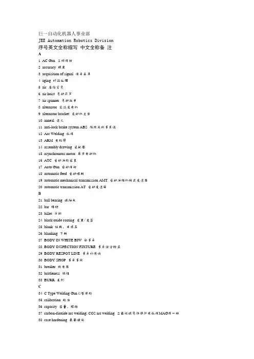
巨一自动化机器人事业部JEE Automation Robotics Division序号英文全称缩写中文全称备注A1 AC Gun 工频焊钳2 accuracy 精度3 acquisition of signal 信号采集4 aging 时效处理5 air 压缩空气6 air hoist 气动葫芦7 air spanner 气动扳手8 alternator 交流发电机9 alternator bracket 发动机支架10 anneal 退火11 anti-lock brake system ABS 防抱死刹车系统12 Arc Welding 弧焊13 ARM 电极臂14 assembly drawing 装配图15 asynchronous motor 异步电动机16 ATC 自动换枪装置17 Auto Gun 自动焊钳18 automatic feed 自动喂料19 automatic mechanical transmission AMT 自动换档机械式变速器20 automatic transmission AT 自动变速箱B21 ball bearing 球轴承22 bar 棒材23 billet 方钢24 black oxide coating 发黑/发蓝25 blank 坯料,半成品26 blanking 下料27 BODY IN WHITE BIW 白车身28 BODY INSPECTION FIXTURE 车身综合检具29 BODY RESPOT LINE 车身补焊线30 BODY SHOP 车身车间31 breaker 断电器32 brittleness 脆性33 BURR 毛刺C34 C Type Welding Gun C型焊枪35 calibration 校准36 capacity 容量,规格37 carbon-dioxide arc welding; CO2 arc welding 二氧化碳气体保护电弧焊MAG焊一种38 case hardening 表面硬化39 catalog 库40 chromium 铬41 clamping force 夹紧力42 Commission 现场调试43 Computer Aided Design CAD 计算机辅助设计44 Computer Numerical Control CNC 计算机数控加工45 concurrent engineering CE 并行工程46 configuration 组态47 control cabinet 控制柜48 control panel 控制屏,控制盘49 control System 操纵系统50 converter 变频器51 coordinate frame of car 车身坐标系52 cotter 开口销53 crack 裂纹54 current gauge 电流测试仪55 cycle time 节拍56 cylinder 气缸1 v1.0巨一自动化机器人事业部JEE Automation Robotics Division序号英文全称缩写中文全称备注D57 damped glue 膨胀减振胶58 data acquisition 数据采集59 data preprocessing 数据预处理60 data Processing 数据处理61 data processor 数据处理器62 DEBUG 程序调试63 definition 定义64 deflection /offset 偏移65 relay 延时66 DIE 冲模67 DIE CHANGER 模具交换器68 digital model 数模69 digital signal processing DSP 数字信号处理70 display 显示71 dowel pin 定位销72 duty ratio 负荷比E73 electric hoist 电动葫芦74 electric welding machine; electric welder 电焊机75 electrically operated valve 电控阀76 electrocladding /plating 电镀77 electrode holder 焊钳78 electromagnetic compatibility EMC 电磁兼容性79 engine 发动机80 epoxy resin glue for hemming 环氧折边胶F81 fault diagnosis 故障诊断82 feedback 反馈83 fender 防护板、翼子板84 field bus 现场总线85 fillet 角焊缝86 fillet welding 角焊87 flange 法兰88 FLEXIBLE BODY LINE FBL 柔性车身线89 flow chart 流程图90 frame/coordination 坐标91 friction stir welding 搅拌摩擦焊G92 gantry 龙门架93 gap 间隙94 gauge 型板95 gears 档位96 Geo-Gripper 定位抓具97 Geometry GEO 几何98 Geo-spot 定位焊点99 gluing 涂胶100 Gluing Robot 涂胶机器人101 governor 调速器102 grinder 磨光机103 gripper 抓具104 groove 坡口105 GUN HANGER 焊钳吊钩106 GUN SWITCH 焊钳开关H107 HAND GUN 手动焊钳108 HANDLING ROBOT 取件机器人;搬运机器人109 hardening and tempering 调质110 heat/thermal treatment 热处理2 v1.0巨一自动化机器人事业部JEE Automation Robotics Division序号英文全称缩写中文全称备注111 hemming 滚边112 HEMMING DIE 包边模具113 Hemming Machine 包边压力机114 HEMMING PRESS 包边压力机115 horizontal 水平116 hot-melt adhesive 热熔胶117 human-machine interface HMI 人机界面I118 induction machine 感应式电机119 information of weld point 焊点信息120 inner dimension 内部尺寸121 INSPECTION FIXTURE I/F 检具122 interference 干涉123 isolating transformer 隔离变压器J124 jog 点动(机器人等)125 joint 运动关节K126 kinematic 运动学的, 运动学上的L127 laser welding/ laser beam welding 激光焊128 layout 规划,布局图129 leg/ fillet weld leg 焊脚130 lifter 升降机131 linear unit 直线单元132 location 位置133 location pin 定位销134 lubricating oil 润滑油M135 main control point chart MCP图136 main reducer 主减速器137 man-machine coordination 人机协调138 MASTER CONTROL POINT MCP 主要控制点139 MASTER CONTROL SECTION MCS 主控截面140 master station 主站141 mechanical transmission MT 机械式变速箱142 mechanism 机构143 Metal Active Gas welding MAG 金属极(熔化极)活性性气体保护焊144 Metal Inert Gas welding MIG 金属极(熔化极)惰性气体保护焊145 MF Gun 中频焊枪146 MIG WELDING MIG焊147 modify 更改148 mounting plate 安装面149 multiple spot welding 多点焊N150 normalizing 正火151 nozzle 喷嘴O152 Off-line Programming OLP 离线编程153 ON-BOARD DIAGNOSTICS OBD 在线检测154 open 大开155 operating mechanism 操作机构156 orientation 方位157 over voltage relay 过电压继电器P158 pallet 物料架,小车托盘159 part drawing 零件图160 peak time 峰值时间161 performance characteristic 工作特性3 v1.0巨一自动化机器人事业部JEE Automation Robotics Division序号英文全称缩写中文全称备注162 pneumatic 气动163 pillar 立柱164 planning 规划165 position 位置166 postweld heat treatment/postheat treatment 焊后热处理167 PRESS 压力机168 Press Line 冲压线169 pressing robot 冲压机器人170 process 工序;工艺(强调过程)171 project 工程、项目、投影172 projection welding 凸焊173 property 属性Q174 quenching 淬火R175 rack 支架176 rail 轨道;横梁177 reachable 可达178 Reinforce glue 补强胶179 reinforcement 加强180 reliability 可靠性181 rigidity 刚度182 Regulator Interface Panel RIP 水气排183 robot programming language 机器人编程语言184 robot simulation 机器人仿真185 robot teaching 机器人示教S186 Sealer Pump 涂胶泵187 seam 接缝188 section 型材,断面189 semiopen小开190 sensor 传感器191 Servo Gun 伺服焊钳192 servo motor 伺服电机193 short-circuiting,bridge 短路194 shuttle 往复输送195 simulated interrupt 仿真中断196 spatter 飞溅197 Spot Welding Sealants 点焊密封胶198 spot welding; resistance spot welding 点焊199 stability 稳定性200 stand 换枪架201 station 工位202 strength 强度203 stud welding 植焊204 summary 摘要205 sun roof 天窗206 surface roughness 表面粗糙度T207 tapping 攻丝208 task 任务209 technique 工艺(强调技术手段)210 temperature control device 温度控制元件211 test signal 测试信号212 TIMER CONTROLLER T/C 焊接控制箱213 TIP 电极帽214 tip dresser 修磨器215 tip; contact tube 导电咀216 tool changer 换枪装置4 v1.0巨一自动化机器人事业部JEE Automation Robotics Division序号英文全称缩写中文全称备注217 torch 焊炬;弧焊焊枪218 touch screen;touch panel 触摸屏219 TRANSFORMER T/R 焊接变压器220 TROLLY 滑车221 Tungsten Inert Gas/Gas Tungsten Arc Welding TIG/GTAW 钨极(非熔化极)惰性气体保护焊;钨极氩弧焊222 TURN TABLE 回转台V223 valve 阀224 velocity transducer 速度传感器225 vertical 垂直226 virtual manufacturing 虚拟制造W227 washer 垫片228 wear and tear 磨损229 weldability焊接性230 welding current downslope time 焊接电流衰减时间231 welding cycle 焊接循环232 welding gun 焊枪233 welding machine; welder 焊机234 welding power source 焊接电源235 welding process 焊接工艺236 Welding Robot 焊接机器人237 welding spot 焊点238 welding technique 焊接技术239 wire cutting 电火花线切割X240 X Type Welding Gun X型焊枪5 v1.0巨一自动化机器人事业部JEE Automation Robotics Division序号英文全称缩写中文全称备注250 ASSEMBLY ASSY 总成BIW Abbr.251 BODY BUILD B/B 总成BIW Abbr.252 BODY COMPLETE B/C 总成BIW Abbr.253 BODY FLOOR B/F 地板BIW Abbr.254 BODY IN WHITE BIW 白车身BIW Abbr.255 BODY SIDE B/S 侧围BIW Abbr.256 BRACKET BRKT 支架BIW Abbr.257 CENTER CTR 中央通道BIW Abbr.258 COMPLETE COMPLT 组件;总成BIW Abbr. 259 DOOR DR 门BIW Abbr.260 ENGINE ENG 发动机BIW Abbr.261 EXTENTION EXTN 延伸BIW Abbr.262 FLOOR FLR 地板BIW Abbr.263 FRONT FR;FRT 前部BIW Abbr.264 HEAD LAMP H/LAMP 前大灯BIW Abbr.265 INNER INR 内部的BIW Abbr.266 LEFT HAND LH 左侧BIW Abbr.267 LOWER LWR 下部BIW Abbr.268 MEMBER MBR 纵梁BIW Abbr.269 OUTER OTR 外部BIW Abbr.270 PANEL PNL 面板BIW Abbr.271 RADIATOR RAD 水箱BIW Abbr.272 RADIATOR SUPPORT R/SUPT 水箱横梁BIW Abbr. 273 REAR RR 后部BIW Abbr.274 REINFORCEMENT REINF 加强BIW Abbr.275 RIGHT HAND RH 右侧BIW Abbr.276 ROOF RF 顶盖BIW Abbr.277 SIDE OUTER S/OTR 外侧BIW Abbr.278 SIDE SILL S/SILL 侧裙边BIW Abbr.279 SUB ASSEMBLY SUB ASSY 分总成BIW Abbr. 280 SUN ROOF S/RF 天窗BIW Abbr.281 SUPPORT SUPT 支撑BIW Abbr.282 UNDERBODY UB 地板BIW Abbr.283 UPPER UPR 上部BIW Abbr.284 intake pipe 进气管BIW285 fire wall,dash panel 前围板BIW286 rear wall 后围板BIW287 tailgate 后背板BIW288 fender 翼子板;挡泥板BIW289 fuel filler 加油口BIW290 front pillar,A-pillar A柱BIW291 center pillar,B-pillar B柱BIW292 rear pillar,C-pillar C柱BIW293 rail 横梁BIW294 hinge 铰链BIW295 guide rail 导轨BIW一级:169个(阴影)编制:欧智华日期:2009.04.156 v1.0__。
(试行)3.规制块的设计要求规范图1 图23.1.规制块尺寸要求常用规制块有如上(图1、图2和图3)三种结构(两销一钉),根据安装要求的不同,中间孔为M8的螺纹孔或ø9的螺钉过孔,两侧的均为ø8H7的销孔。
其尺寸要求如下(表2)所示:尺寸类型要求尺寸大小(mm)第一系列第二系列加工公差要求L 60 45B1 16 16H 根据板件型面的形状来确定±0.02L1 15 15L2 15 15B2 8 8 ±0.05S1 10 10 ±0.05S2 25 25 ±0.02S3 12.5 12.5表23.2.技术要求3.2.1. 材质要求:规制块的材料要求必须为45#钢并要进行热处理,使规制块工作面的表面硬度达到HRC30~35,工作面的粗糙度为,同时规制块要进行表面发蓝处理。
3.2.2. 在遇到如图4所示的板件结构时(需同时规制板件的两个面),要采用两个单独的规制块分别进行规制,不允许使用如图5所示的结构形式,如特殊情况会签时需经奇瑞公司确认后方可使用。
3.2.3. 规制块设计时原则上要求与板件垂直(图6),若因特殊情况不能保证时,则规制块的压紧方向最大斜角(图7)不大于15°,若大于该角度则需要使用导引挡块(CATCH STOPPER)。
图6 图73.2.4. 第一系列的规制块要优先选用,若设计时的空间不够或选用第一系列无法装配时,可以选用第二系列所规定的规制块,但装配时要便于人员的操作,会签时需经奇瑞公司确认后方可实施。
3.2.5. 规制块压紧时要求每个规制块所能达到的压力F(图8)范围为:25kgf≤F≤30kgf,气缸选用时要依此作为依据。
4.调整垫片的设计要求规范图95.角座的设计要求规范6.BASE板的设计要求规范图136.1.常用尺寸要求如表5所示尺寸类型常用尺寸大小(mm)S(面积:单位m²) S≤0.5 0.5<S≤0.8 0.8<S≤2.0 S>2.0 H1 20 20 22 25H2 15 15 15 15坐标网格线的平行度误差要求:相邻单一间隔距0.10mm/100mm;累积间隔距0.30mm/全长。
译文标题精密机械加工工艺原文标题Precision Machining Technology作者Peter J. Hoffman 译名彼得·J·霍夫曼国籍美国原文出处Cengage Learning译文:在机械加工过程中,工件受到切削力、离心力、惯性力等的作用,为了保证在这些外力作用下,工件仍能在夹具中保持已由定位元件确定的加工位置,而不致发生振动或位移、夹具结构中应设置夹紧装置将工件可靠夹牢。
一、夹紧装置的组成夹紧装置的种类很多,但其结构均由两部分组成。
1 .动力装置夹紧力的来源,一是人力;二是某种装置所产生的力。
能产生力的装置称为夹具的动力装置。
常用的动力装置有:气动装置、液压装置、电动装置、电磁装置、气—液联动装置和真空装置等。
由于手动夹具的夹紧力来自人力,所以它没有动力装置。
2 .夹紧部分接受和传递原始作用力使之变为夹紧力并执行夹紧任务的部分,一般由下列机构组成:1 )接受原始作用力的机构。
如手柄、螺母及用来连接气缸活塞杆的机构等。
2)中间递力机构。
如铰链、杠杆等。
3 )夹紧元件。
如各种螺钉压板等。
其中中间递力机构在传递原始作用力至夹紧元件的过程中可以起到诸如改变作用力的方向、改变作用力的大小以及自锁等作用。
二、夹紧装置的基本要求在不破坏工件定位精度,并保证加工质量的前提下,应尽量使夹紧装置做到:1.夹紧力的大小适当。
既要保证工件在整个加工过程中其位置稳定不变、振动小,又要使工件不产生过大的夹紧变形。
2 .工艺性好。
夹紧装置的复杂程度应与生产纲领相适应,在保证生产效率的前提下,其结构应力求简单,便于制造和维修。
3 .使用性好。
夹紧装置的操作应当方便、安全、省力。
三、基本夹紧机构原始作用力转化为夹紧力是通过夹紧机构来实现的。
在众多的夹紧机构中以斜楔、螺旋、偏心以及由它们组合而成的夹紧机构应用最为普遍。
(一)紧机构 采用斜传力元紧元紧机斜楔 机构。
直接采用,斜楔条件是:斜楔的升角小于斜楔与工 件、斜 具的摩擦角之和。
讨论和分析现代计算机辅助夹具设计方法Iain 波以耳、Yiming Rong,戴维布朗关键字:计算机辅助夹具设计;夹具设计;夹具设计;夹具确认;装备设计;元件设计摘要现代市场是一个主要为满足消费者多样性需求的地方。
为了种有效地回应这要求,制造业者确定他们的制造业拥有充分的柔性以满足他们迅速的生产发展的需要。
夹具设计,是指使用夹具在制造过程中装夹工件,以便他们能被加工成满足设计规格的产品,是提高制造业柔性一个重要的有利因素。
为了使有柔性的夹具成为可能,已经有相当程度的研究努力热衷于使用计算机辅助夹具设计(CAFD)工具和方法发展辅助夹具设计。
这篇文献包含这些研究努力的讨论。
超过七十五个CAFD 工具和方法在夹具设计方面被讨论并逐步实行计算机辅助和以其为基础的技术。
讨论的主要结论是当已经被在辅助夹具设计方面有重要的进步时,主要地有两个需要进一步的努力的研究议题。
第一,现在的CAFD 研究在本质上被分割,而且需要提供更多前后关联的夹具设计支持。
第二,更多聚焦于一个夹具的自身结构的详细设计。
2010 Elsevier 公司版权所有目录1. 介绍……………………………………………………………………………………………22. 夹具设计………………………………………………………………………………………23. 目前CAFD 的方法.......................................................................................4 3.1 设置规划.............................................................................................4 3.1.1 满足要求的设置规划 (4)3.2 夹具设计.............................................................................................4 3.2.1 达成定义夹具需求的方式...............................................................6 3.2.2 达成方法优化的布局规划...............................................................6 3.2.3 达成规划优化的方式 (6)3.3 元件设计…………………………………………………………………………………7 3.3.1 达成概念上的元件设计的方式…………………………………………………7 3.3.2 达成详细的元件设计的方式……………………………………………………7 3.4 确认………………………………………………………………………………………8 3.4.1 达成约束需求确认的方式………………………………………………………8 3.4.2达成公差需求确认的方式...............................................................8 3.4.3 达成碰撞检测需求确认的方式.........................................................8 3.4.4 达成可用性和供应的方式需求确认...................................................9 3.5 夹具数据的表现....................................................................................94. CAFD 研究的分析..........................................................................................9 4.1 CAFD 研究的被分割的性质 (9)4.2 有效地辅助元件设计...........................................................................10 4.3 综合地明确地叙述夹具需求 (10)4.4 确认CAFD 研究输出……………………………………………………………………105. 结论……………………………………………………………………………………………10 参考文献…………………………………………………………………………………………101. 介绍制造业企业的主要担心是发展设计和在短时间范围里生产多种高质量产品的能力。
附录一:汽车的部件发动机发动机的作用是为汽车提供动力,人们形象的称之为汽车的动力工厂。
大多数汽车发动机都是利用空气和汽油混合物的爆炸能量推动活塞的。
活塞能够转动与它连接在一起的曲柄连杆。
从而,曲柄产生牵引力使车轮转动。
有些汽车是靠另一种发动机来提供动力的。
这种发动机因为它的旋转阀,旋转内燃机或者转子发动机而被人熟知。
这种旋转阀式发动机也能够吸入空气和燃料的混合物,然后将它们压缩并燃烧。
另外,发动机会在一个椭圆形腔室中旋转,它与驱动汽车后轮的后轴相连接。
绝大多数的汽车里,发动机会被安装在汽车的前部末端,离合器和变速箱在它的后面。
最后,发动机、离合器和变速箱会被装配成一个整体。
想要使一个发动机能够正常工作还需要很多系统的支持。
润滑系统可以用来减小摩擦,减轻发动机磨损。
冷却系统可以使发动机的工作温度在安全的范围之内。
另外,发动机还必须由供油系统提供适量的燃料和空气。
在气缸里,空气和燃料的混合物必须由点火系统在适当的情况下点燃。
而后,电子系统被用来控制启动发动机用的电动机和为发动机的附属部件提供电能。
润滑系统发动机的部件会因为它们之间的相互运动而逐渐导致磨损。
在这些部件中间存在着发动机循环油。
它可以避免金属间的相互摩擦而导致的磨损。
在润滑剂的润滑作用下,各部件会仅受到很小的摩擦力,这可以使它们更容易运动。
因此,润滑系统可以将由摩擦引起的能量损失降到最小。
润滑剂的第二个作用是可以发挥冷却剂的作用,也可以作为密封介质来防止泄漏。
还有在气缸上产生的润滑薄膜也可以有助于活塞环密封,改善发动机的压缩性能。
冷却系统在气缸中,燃料会在空气的作用下剧烈燃烧,从而导致发动机各部件的温度升高。
温度的上升将直接影响发动机的性能,也会缩短发动机零件的寿命。
而冷却系统则可以使发动机在适宜的温度下工作。
无论驾驶条件如何,该系统都要被设计用来防止机器过冷或过热。
燃料供给燃料供给系统的主要作用是在机动车辆所能遇到的所有条件下(包括负载,速度,温度压力的变化梯度等),提供足够的压力,以一定的速度为化油器或注油系统提供燃料,来满足发动机的燃料要求。
文献综述矿山机电11-1 孙祥 1107250120汽车白车身焊装夹具定位基准的设计The design of automotive body-in-white welding fixturelocating datum汽车白车身焊装夹具定位基准的设计摘要:汽车工业是当代最重要的工业,也是我国国民经济的支柱产业。
而汽车车身是汽车的重要组成部分,也是汽车其它零部件的基础,其制造质量对整车的质量和汽车的市场竞争力起重要作用。
本文首先分析了白车身的结构及其焊装流程,重点研究白车身焊装夹具的结构、特点和基准设计等。
关键词:焊装夹具;基准设计The design of automotive body-in-white welding fixturelocating datumAbstract:The automotive industry is of the most important industry, the pillar industry of China's national economy. Auto body is an important part of the car, but also in other parts of the car based on the quality of its manufacturing plays an important role on vehicle quality and market competitiveness of the car. This paper first analyzes the body-in-white structure and its welding process, focusing on the structure, characteristics and baseline body-in-white welding fixture design.Keywords: body-in-white; welding lines; welding fixture; benchmark design1.汽车白车身白车身一般指车身生产流程中在完成车身焊装但未进行涂装工艺的白皮车身,包括车身制件和车门等.结构为形状复杂的空间薄壁壳体。
汽车焊接夹具设计外文文献翻译汽车焊接夹具设计外文文献翻译(含:英文原文及中文译文)文献出处:Semjon Kim.Design of Automotive Welding Fixtures [J]. Computer-Aided Design, 2013, 3(12):21-32.英文原文Design of Automotive Welding FixturesSemjon Kim1 AbstractAccording to the design theory of car body welding fixture, the welding fixture and welding bus of each station are planned and designed. Then the fixture is modeled and assembled. The number and model of the fixture are determined and the accessibility is judged. Designed to meet the requirements of the welding fixture.Keywords: welded parts; foundation; clamping; position1 IntroductionAssembly and welding fixtures are closely related to the production of high-quality automotive equipment in automotive body assembly and welding lines. Welded fixtures are an important part of the welding process. Assembly and welding fixtures are not only the way to complete the assembly of parts in this process, but also as a test and calibration procedure on the production line to complete the task of testing welding accessories and welding quality. Therefore, the design and manufacture ofwelding fixtures directly affect the production capacity and product quality of the automobile in the welding process. Automotive welding fixtures are an important means of ensuringtheir manufacturing quality and shortening their manufacturing cycle. Therefore, it is indispensable to correctly understand the key points of welding fixture design, improve and increase the design means and design level of welding fixtures, and improve the adjustment and verification level of fixtures. It is also an auto manufacturing company in the fierce competition. The problem that must be solved to survive.The style of the car is different from that of the car. Therefore, the shape of the welding jig is very different. However, the design, manufacture, and adjustment are common and can be used for reference.2. Structural design of welding fixtureThe structure design of the welding fixture ensures that the clip has good operational convenience and reliable positioning of the fixture. Manufacturers of welding fixtures can also easily integrate adjustments to ensure that the surfaces of the various parts of the structure should allow enough room for adjustments to ensure three-dimensional adjustment. Of course, under the premise of ensuring the accuracy of the welding jig, the structure of the welding jig should be as simple as possible. The fixture design is usually the position of all components on the fixture is determined directly based on the design basis, and ultimately ensure thatthe qualified welding fixture structure is manufactured. According to the working height, the height of the fixture bottom plate can be preliminarily determined, that is, the height of the fixture fixing position. The welding fixture design must first consider the clamping method. There are two types, manual and pneumatic. Manual clamping is generally suitable for small parts, external parts, and small batches of workpieces. For large bodyparts, planning in the production line, automation High-demand welding fixtures should be pneumatically clamped. Automobile production is generally pneumatically clamped, and manual mass clamping can be used as auxiliary clamping. This can reduce costs accordingly. Some manual clamping products already have standard models and quantities, which can be purchased in the market when needed. For some devices, pneumatic clamping is specified, but if pneumatic clamping is used, the workpiece may be damaged. Therefore, it is possible to manually press the place first to provide a pneumatic clamping force to clamp the workpiece. This is manual-pneumatic. . The fixture clamping system is mounted on a large platform, all of which are fixed in this welding position to ensure that the welding conditions should meet the design dimensions of the workpiece coordinate system positioning fixture, which involves the benchmark.3. Benchmarks of assembly and welding fixtures and their chosen support surfaces3.1 Determination of design basisIn order to ensure that the three-dimensional coordinates of the automatic weldment system are consistent, all welding fixtures must have a common reference in the system. The benchmark is the fixture mounting platform. This is the X, Y coordinate, each specific component is fixed at the corresponding position on the platform, and has a corresponding height. Therefore, the Z coordinate should be coordinated, and a three-dimensional XYZ coordinate system is established. In order to facilitate the installation and measurement of the fixture, the mounting platform must have coordinates for reference. There are usually three types. The structure is as follows:3.1.1 Reference hole methodThere are four reference holes in the design of the installation platform, in which the two directions of the center coordinates of each hole and the coordinates of the four holes constitute two mutually perpendicular lines. This is the collection on the XY plane coordinate system. The establishment of this benchmark is relatively simple and easy to process, but the measurements and benchmarks used at the same time are accurate. Any shape is composed of spatial points. All geometric measurements can be attributed to measurements of spatial points. Accurate spatial coordinate acquisition is therefore the basis for assessing any geometric shape. Reference A coordinated direction formed by oneside near two datums.3.1.2 v-type detection methodIn this method, the mounting platform is divided into two 90-degree ranges. The lines of the two axes make up a plane-mounted platform. The plane is perpendicular to the platform. The surface forms of these two axis grooves XY plane coordinate system.3.1.3 Reference block methodReference Using the side block perpendicular to the 3D XYZ coordinate system, the base of a gage and 3 to 4 blocks can be mounted directly on the platform, or a bearing fixing fixture platform can be added, but the height of the reference plane must be used to control the height , must ensure the same direction. When manufacturing, it is more difficult to adjust the previous two methods of the block, but this kind of measurement is extremely convenient, especially using the CMM measurement. This method requires a relatively low surface mount platform forthe reference block, so a larger sized mounting platform should use this method.Each fixture must have a fixed coordinate system. In this coordinate system, its supporting base coordinate dimensions should support the workpiece and the coordinates correspond to the same size. So the choice of bearing surface in the whole welding fixture system 3.2When the bearing surface is selected, the angle between the tangentplane and the mounting platform on the fixed surface of the welding test piece shall not be greater than 15 degrees. The inspection surface should be the same as the welded pipe fittings as much as possible for the convenience of flat surface treatment and adjustment. The surface structure of the bearing should be designed so that the module can be easily handled, and this number can be used for the numerical control of the bearing surface of the product. Of course, designing the vehicle body coordinate point is not necessarily suitable for the bearing surface, especially the NC fixture. This requires the support of the fixture to block the access point S, based on which the digital surface is established. This surface should be consistent with the supported surface. So at this time, it is easier and easier to manufacture the base point S, CNC machining, precision machining and assembly and debugging.3.2 Basic requirements for welding fixtureIn the process of automobile assembly and production, there are certain requirements for the fixture. First, according to the design of the automobile and the requirements of the welding process, the shape, size and precision of the fixture have reached the design requirements and technical requirements. This is a linkthat can not be ignored, and the first consideration in the design of welding fixture is considered. When assembling, the parts or parts of the assembly should be consistent with the position of the design drawings of the car and tighten with the fixture.At the same time, the position should be adjusted to ensure that the position of the assembly parts is clamped accurately so as to avoid the deformation or movement of the parts during the welding. Therefore, this puts forward higher requirements for welding jig. In order to ensure the smooth process of automobile welding and improve the production efficiency and economic benefit, the workers operate conveniently, reduce the strength of the welder's work, ensure the precision of the automobile assembly and improve the quality of the automobile production. Therefore, when the fixture design is designed, the design structure should be relatively simple, it has good operability, it is relatively easy to make and maintain, and the replacement of fixture parts is more convenient when the fixture parts are damaged, and the cost is relatively economical and reasonable. But the welding fixture must meet the construction technology requirements. When the fixture is welded, the structure of the fixture should be open so that the welding equipment is easy to close to the working position, which reduces the labor intensity of the workers and improves the production efficiency.4. Position the workpieceThe general position of the workpiece surface features is determined relative to the hole or the apparent positioning reference surface. It is commonly used as a locating pin assembly. It is divided into two parts: clamping positioning and fixed positioning. Taking into account thewelding position and all welding equipment, it is not possibleto influence the removal of the final weld, but also to allow the welding clamp or torch to reach the welding position. For truly influential positioning pins and the like, consider using movable positioning pins. In order to facilitate the entry and exit of parts, telescopic positioning pins are available. The specific structure can be found in the manual. The installation of welding fixtures should be convenient for construction, and there should be enough space for assembly and welding. It must not affect the welding operation and the welder's observation, and it does not hinder the loading and unloading of the weldment. All positioning elements and clamping mechanisms should be kept at a proper distance from the solder joints or be placed under or on the surface of the weldment. The actuator of the clamping mechanism should be able to flex or index. According to the formation principle, the workpiece is clamped and positioned. Then open the fixture to remove the workpiece. Make sure the fixture does not interfere with opening and closing. In order to reduce the auxiliary time for loading and unloading workpieces, the clamping device should use high-efficiency and quick devices and multi-point linkage mechanisms. For thin-plate stampings, the point of application of the clamping force should act on the bearing surface. Only parts that are very rigid can be allowed to act in the plane formed by several bearing points so that the clamping force does not bend the workpiece or deviate from the positioning reference. In addition, it must be designed so that it does not pinch the hand when the clamping mechanism is clamped to open.5. Work station mobilization of welding partsMost automotive solder fittings are soldered to complete in several processes. Therefore, it needs a transmission device.Usually the workpiece should avoid the interference of the welding fixture before transmission. The first step is to lift the workpiece. This requires the use of an elevator, a crane, a rack and pinion, etc. The racks and gears at this time Structure, their structural processing, connection is not as simple as the completion of the structure of the transmission between the usual connection structure of the station, there are several forms, such as gears, rack drive mechanism, transmission mechanism, rocker mechanism, due to the reciprocating motion, shake The transfer of the arm mechanism to the commissioning is better than the other one, so the common rocker arm transfer mechanism is generally used.6 ConclusionIn recent years, how to correctly and reasonably set the auxiliary positioning support for automotive welding fixtures is an extremely complicated system problem. Although we have accumulated some experience in this area, there is still much to be learned in this field. Learn and research to provide new theoretical support for continuous development and innovation in the field of welding fixture design. Withthe development of the Chinese automotive industry, more and more welding fixtures are needed. Although the principle of the fixture is very simple, the real design and manufacture of a high-quality welding fixture system is an extremely complicated project.中文译文汽车焊接夹具的设计Semjon Kim1摘要依据车体焊装线夹具设计理论, 对各工位焊接夹具及其焊装总线进行规划、设计, 之后进行夹具建模、装配, 插入焊钳确定其数量、型号及判断其可达性,最终设计出符合要求的焊接夹具。
Int J Adv Manuf Technol(2001)18:266–275 2001Springer-Verlag LondonLimitedPrinciple and Simulation of Fixture Configuration Design for Sheet Metal Assembly with Laser Welding.Part1:Finite-Element Modelling and a Prediction and Correction MethodB.Li,B.W.Shiu and uDepartment of Mechanical Engineering,Hong Kong Polytechnic University,Kowloon,Hong KongThe quality of the stamping process has a direct effect on laser welded sheet metal assembly.Thefixture plays an important role in the satisfactory metalfit-up that laser welding requires.The traditional“3-2-1”locating scheme will no longer suffice for the deformable laser sheet metal assembly process.Because of the often poor stamping quality,a complex diefixture has to be employed to meet the metalfit-up require-ments.The diefixture corresponds to an“infinite-2-1”locating scheme where the tooling cost is very high and yet lacks flexibility.This limits the application of laser welding.In this paper,a new locating scheme with both total locating and direct locating for welds is proposed.A total locating scheme is used to locate the overall assembly,and a direct locating scheme is used to locate the weld location,which is critical for ensuring correct metalfit-up.Afinite-element model and a prediction and correction method for the direct locator configuration are developed in this paper.A case study is used to show that the proposed method is effective for sheet metal assembly for laser welding.Keywords:Fixture configuration design;Laser welding;Locat-ing scheme;Sheet metal assembly1.IntroductionThe process of automotive body assembly involves joining sheet metal components to form a body-in-white(BIW) assembly.Welding contributes to much of the assembly pro-cess.Sheet metal assembly with laser welding has numerous advantages over traditional welding techniques,such as,a small heat affected zone and a single weld plane,high strength and highflexibility;also,laser welding is more suitable for subassemblies with high weld density,long linear rows of welds or weld locations around the assembly periphery. Correspondence and offprint requests to:B.Li,Department of Mech-anical Engineering,Hong Kong Polytechnic University,Kowloon,Hong Kong.E-mail:99900107rȰ.hk Because of the high weld quality and relatively low manufactur-ing cost,laser welding has great potential for replacing other welding techniques.However,a few problems related to laser welding limit its application in industry.When laser welding is applied in the assembly process,metalfit-up becomes crucial in ensuring correct implementation of laser welding and in improving weld quality[1].However,the capability of the current stamping process cannot satisfy the metalfit-up accu-racy required by laser welding.In1974,the United Technology Corporation delivered a6kW CO2laser to the Ford Motor Company for underbody welding,but the equipment never went into production because of thefit-up problems experienced[2]. The assemblyfixture plays an important role in sheet metal assembly.In the assembly process,each panel is positioned relative to the other panels and secured in place.After being properly positioned,the panels are welded together[3].In the assembly with resistance spot welding(RSW),fixture con-figuration design is developed to reduce the deformation of each workpiece owing to the welding and,hence,to reduce the dimensional variation of the assembly[4,5].Since the weld gun will cause heat and high local weld tip pressure during the welding process,thefixture has little effect on the accuracy of the welding operation.However,in the assembly process using laser welding,the factors to be considered are quite different.To overcome the poorfit-up problem,thefixturing and clamping become more extensive and expensive[6].In recent years,work has been focused on automating the fixture design processes.Most workers consider the workpiece to be a rigid part.Asada and By[7]systematically conducted a kinematic analysis for an automatically reconfigurablefixture and the rigid workpieces are modelled as simply connected piecewise smooth surfaces.Lee and Haynes[8]proposed a finite-element model of afixturing system analysis for prismatic parts.Most research onfixture design is based on the assump-tions of point contact and frictionless locating.De Meter[9] developed afixture design by taking planar,spherical,and cylindrical surface contacts between workpiece andfixture elements.Very little work has been carried out on thefixture design of deformable sheet metal assemblies.Rearick et al.[4] proposed a method which combines nonlinear programmingFixture Con figuration Design.Part 1267and finite-element analysis to design and evaluate fixtures for deformable sheet metal workpieces.Cai et al.[5,10]set up a principle and algorithm for an assembly fixturing scheme for deformable sheet metal with RSW and developed a fixture design package.An optimal fixture con figuration was presented for sheet metal assembly based on RSW,considering the in fluence of assembly springback.The work which has been reported on assembly fixture design for sheet metal assembly with laser welding is limited.In particular,there is no report on assembly fixture design for deformable sheet metal using laser welding.The typical laser welding joints for car body parts are shown in Fig.1.These weld joints can be regarded as two basic weld joints:a lap joint and a butt joint.In butt jointing,filler materials can be added to bridge the gap caused by poor fit-up,instead of using complicated and expensive fixtures.In lap jointing,there is no way to solve the fit-up problem without the aid of traditional fixturing.The objective of this paper is to develop a generic assembly fixture design method for the lap joint in sheet metal assembly with laser welding.This consists of finding a way to carry out fixture con figuration to satisfy the desired metal fit-up.This paper is concerned with finite-element modelling and a prediction and correction method.A separate paper,Part 2[11],will address the optimal fixture con figuration design issue.This paper is organised as follows.In Section 2,a new locating scheme for laser welding is proposed and in Section 3a finite-element modelling for fixture con figuration design is developed taking the features of laser welding into account.In Section 4,a prediction and correction method for con figuration design of direct locators is proposed;a case study and summary are given in Sections 5and6.Fig.1.Typical laser welding joints for car bodyparts.Fig.2.“3-2-1”locating scheme.2.Locating Scheme:from “3-2-1”to “in finite-2-1”The traditional “3-2-1”locating scheme based on a rigid workpiece is shown in Fig.2.There are 6degrees of freedom and 12directions of motion for any rigid body [12].Each locator prohibits movement in one degree of freedom,therefore,for complete part location,6locators are required.Figure 2shows the 6locators restraining the 6degrees of freedom.As shown in the figure,A 1,A 2,and A 3are de fined in the primary datum plane A and restrain translation in the z -direction,and rotation about the x -and y -axes;B 1and B 2are de fined in the secondary datum plane B and restrain translation in the x -direction and rotation about the z -axis;C 1is de fined in the tertiary datum plane C and restrains translation in the y -direc-tion.A typical “3-2-1”locating scheme is enough to locate a rigid body with the minimum number of locators.However,since sheet metal is compliant,the “3-2-1”locating scheme cannot satisfactorily meet a close tolerance speci fication.In order to obtain better assembly quality in the assembly process with RSW,a “N -2-1”(N Ն3)locating scheme has been proposed by Cai [5].As mentioned above,sheet metal assembly with laser weld-ing fixtures not only functions to control the assembly variation,but is also needed to ensure fit-up of the mating surfaces to ensure proper laser beam weld operation and laser weld quality.However,the current process of stamping cannot meet the accuracy of metal fit-up required.For poor quality panels,laser welding can be carried out only with the aid of a complex die fixture,which corresponds to an “in finite-2-1”locating ser welding with a complex fixture is shown in Fig.3.Although by this scheme the welding quality can be improved,the tooling cost is too great and the tooling also lacks flexibility.These drawbacks will limit its industrial application.In this paper,a new locating scheme with both total locating and direct locating for welds is proposed instead of the “in fi-nite-2–1”locating scheme.The total locating scheme isusedser welding with complex fixtures.268 B.Li et al.to locate the entire sheet metal assembly.The direct locating scheme is used to locate the weld joints to meet the metalfit-up requirement.This new locating scheme for the laser welding process for lap-joint sheet metal assembly is shown in Fig.4. From Fig.4(a),we can see that the two mating panels are located by totalfixtures and direct locators are not applied.In this case poor metalfit-up on the welding area will result.In Fig.4(b),direct locators are applied and metalfit-up degree is improved in the welding area.In Fig.4(c),the laser beam weld joins the two parts together.The laser welding process does not require pressure,but requires intimate metal contact at the surface interface to ensure success.The metalfit-up is critical for ensuring both a proper implementation of the weld operation and the precision with which sheet metal parts are manufactured.A large joint gap will result in a reduced weld cross-sectional area,hence,reduc-ing both the static and fatigue strength of the weld[1].The main task offixture configuration for sheet metal laser welding is the development of a direct locating scheme for welds. Configuration design of the direct locating scheme includes the determination of the number and location of the direct locators. A“3-2-1”locating scheme for the overall assembly is con-sidered in this paper.3.Finite-Element Modelling for FixtureConfiguration DesignThefixture configuration design for sheet metal assembly with resistance spot welds[4,5]controls the total deformation of the nodes involved when the weld force is applied,regardlessof the source of variation of the nodes resulting fromeitherFig.4.An illustration of sheet metal laser welding with new locating scheme.(a)Totalfixture applied.(b)Direct locators applied.(c)Laser beam operation.the stamping process or the assembly process.In this way,the sheet metal is modelled as aflat plane without variational tolerance.However,it is rather different from thefixture configuration design with laser welding.The degree of metal fit-up is process-dependent,so the quality of the stamping process directly affects the panel variation.In this case,statisti-cal information on stamping is required for the sheet metal modelling.3.1Geometric ModellingTheoretically,the more information there is about the source of the variation,the better the modelling accuracy.In the BIW process it is not economically or logistically feasible to measure many points,so a certain measuring density(say,30mm) should be specified for geometric modelling.Generally,the measured data are chosen randomly.In order to generate a feasiblefinite-element model which reflects the quality level of the stamping process,a distribution of the standard deviation should be used to simulate the variational tolerance in some subassemblies.The number of measurement samples should be at least30,so that the calculated standard deviation can reflect the variational nature of the assembly/subassembly.In this paper,the standard deviation is considered to be the source variation along the direction of the normal to the panels.Aflowchart for geometric modelling is shown in Fig.5,in which statistical data is used to construct the standard deviation with a data matrix[A]mϫn,where m and n refer to the number of measurement points in rows and columns,respectively. There are many ways to generate the curve,but,to ensure the smoothness of the curve,a spline curve is adopted with on-curve modelling data.Based on the parasolid geometry engine (MSC/NASTRAN),a lofted surface between a series of curves can befitted.The advantage of this engine is that thefitted curves will be on the constructed surface.After this step,a finite-element mesh is generated.To meet the metalfit-up Fig.5.Flowchart of geometric modelling.Fixture Configuration Design.Part1269 requirement,the mesh size should be high enough,say4mϫ4n.Then,a normal distribution test for all mesh nodes is carriedout to see if the measured points are enough for ensuring thenormality of the data on the surface.From the normal prob-ability plot,the linearity of the relevant data can be seen.Ifthe data satisfy the normal distribution,the plot should belinear.If it does not,the number of measured points shouldbe increased.Thus,a geometric model forfinite-element analy-sis(FEA)is set up.An example for geometric modelling is shown in Fig. 6.Thefigure shows thefinite-element model for two matingpanels using the“3-2-1”locating scheme.From thisfigure,wecan see that the two panels are not planes but two surfaceswith source variation.In the process of assembly,the twopanels will connect together,but for illustration purposes,inthisfigure the two panels are deliberately moved apart.Thedimensions of the two panels are the same,being200mmϫ100mmϫ1mm.The measurement data is generated byMonte Carlo simulation with a statistical distribution.For agood stamping workshop,the6value can be as low as1.5mm.This value is used as the distribution value for this paper.Thus,the source variation is along the z-direction and themeasurement density of20mm is along the edges.The meas-ured points on each panel are in6columns by11rows.Themesh size of the generated surface is5mm,the generatednodes are41nodes by21nodes.Thus,the number of nodeson each panel is841,a normal probability plot of the sourceof variation for one panel is shown in Fig.7,which shows thatthe linearity is acceptable for the assumed normal distribution.3.2.Element,Constraint,and LoadSheet metal can be modelled by plate or shell elements forfinite-element(FE)analysis.In this paper,a quadrilateral plateelement is employed for sheet metal modelling.For sheet metalassembly,the spring elements(MSC/NASTRAN)are used tomodel the welding joint connecting corresponding nodes onthe weld stitch location.As shown in Fig.6,five mating nodeswhich represent a20mm-long weld stitch are connected byfive spring elements.In thefixture configuration design thestiffness of the spring element should be small enough toensure that the effects of the locators are well modelledandFig.6.Illustrative FEM of a sheet metalassembly.Fig.7.Normal probability plot for one panel.the orientation of the element can be the actual direction ofthe welding force.In sheet metal assembly with RSW,theapplied pressure of the weld gun is an external load.In laserweld assembly,no such external load is applied.Hence,thefixture will play a more important role than in the case of RSW.Generally thefixture elements include pins and locator/clamps in the automotive industry.The“2-1”locating schemeis realised by a4-way pin and a2-way pin.An example ofthe two pins for a simple sheet metal assembly is shown inFig.8.From thisfigure,we can see that the4-way pin restrainsthe movement of the two sheet metals along the x-axis andthe y-axis,and the2-way pin restrains the movement onlyalong the y-axis.It is appropriate that the two pins are modelledas constraints for in-plane motion in the FE model.In the FEmodel,the constraints of the4-way pin and2-way pin arelabelled,respectively,as“12”and“2”,as shown in thefigure.One function of a locator is to constrain the one-way motion(along the z-axis)which can be modelled as a constraint.Theother function is to clamp contact points to designed nominalvalues by a correct clamping force.Hence,only modelling thelocator as a constraint is not enough.In order to resolve thisissue,the indeterministic clamping force on the panel appliedby the locator can be determined.Owing to the nonlinearinfluence of geometry,material,and boundary,etc.,it is diffi-cult to achieve enough accuracy.Enforced displacement inthefinite-element modelling can be employed for the locatormodelling.The enforced displacement can fulfil the dual func-tions of locators.It is treated as an applied load(this isimportant to ensure the true representation of the FEA process).However,it is actually a displacement constraint and isthere-Fig.8.Two pins of a simple assembly.270 B.Li et al.fore a boundary condition.In FEM,the locator is assumed to be a point contact without thermal in fluence.3.3Criterion for Degree of Metal Fit-up (DMF)and Direct Locating Area (DLA)The degree of metal fit-up (DMF)is a measurement of the intimacy of the weld joint interface.It can be evaluated by the maximum distance between the mating nodes on the weld joint.Generally speaking,it is acceptable if the degree of metal fit-up is within 15%of the impact metal thickness (IMT)[1].IMT refers to the thickness of the part that the laser first impacts.As shown in Fig.1(a ),in order to form a lap joint,the laser will first impact the upper part,in this way the thickness of the upper part is just the IMT.In this paper,the evaluation criterion of the DMF is set as follows:DMF Յ0.1IMT or max (abs(DIS j ii Ј))Յ0.1IMT(1)i =1,2,%,n w ,i Ј=1Ј,2Ј,%,n Јw ,j =1,2,%,n Where DIS j ii Јrefers to the distance between the i th node onthe upper panel and the i th mating node on the lower panel to the j th weld stitch.n w and n Јw represent the nodal number on the weld stitch of the two panels,and n represents the total number of weld stitches to the fixture design.The calculation of DSI j ii Јis described as follows:from the geometrical model,the nodal coordinates X i and X i Јon the weld stitch with source variation can be obtained.After the fixture is applied,the deformation ⌬X i and ⌬X i Јof the corre-sponding nodes can be obtained from the FEA calculation,then the distance DIS j ii Јcan be written as:DIS j ii Ј=(X i +⌬X i )−(X i Ј+⌬X i Ј)(2)i =1,2,%,n w ,i Ј=1Ј,2Ј,%,n Јw ,j =1,2,%,nIn this paper,the location area of the direct locators is de fined as the direct locating area (DLA).The DLA is generally located around the weld stitch.As shown in Fig.9(a ),the DLA labelled with squares is a curve along a -b -c -d and the weld stitch is labelled with a circle.If the weld stitch is not a straight line,the DLA can be an arbitrary curve around the weld stitch.The actual locator has structural dimension and the minimal mesh size L 0should be speci fied by the designer,in this paper it is limited to L 0Ն5mm.4.Prediction and Correction Method for Con figuration of Direct LocatorsIt has been mentioned above that the application of direct locators on a weld stitch is critical for satisfying the DMF laser welding required.If direct locators are applied on all nodes distributed on the DLA,this locating scheme corresponds to a die fixture.It is unreasonable to adopt this scheme considering the cost and flexibility.So in this paper,a new design method called the prediction and correction method is proposed for finding the number and location of the directlocators.Fig.9.Local weld stitch models for (a )single short weld,(b )singlelong weld,and (c )two short welds.The main points of this method are as follows.When the designed locators are applied on the nodes of the DLA,differ-ent nodes on which the locators are applied will have different contributions to the achievement of the DMF for the weld joint.If we know the relative contributions of these nodes,it will be easier to carry out locator con figuration.Since the aim of the fixture con figuration is to obtain a satisfactory DMF for the welding nodes,a method using inverse logic is proposed.We first set all welding nodes to the designed nominal values,then the variational information about the nodes on the DLA can be obtained by FEA.If the designed locators are applied on the nodes with a relatively big variation,the variation of the nodes on the welding joint will be signi ficantly reduced.Based on this idea,we can group the nodes on the DLA according to their variations,then the locator con figuration can be carried out according to these groups.A flowchart of the prediction and correction method is shown in Fig.10.For the whole sheet metal assembly,a “3-2-1”locating scheme is applied.The three main steps of this method are discussed in detail.1.Drawing of Nodal Variation Graph (NVG).First,the nodes of the weld stitch are set to the designed nominal values,thus,the variation of the welding nodes will be zero.After running the FEA,the variation of the nodes on the DLA can be extracted from the output file of the FEA.According to Eq.(2),the distances between mating nodes on the DLA can be calculated,thus a nodal variation graph for the zero nodal variation of the welding nodes can be obtained.Figure 11shows a drawing of an NVG.The two mating panels have the same dimensions:200mm ϫ100mm ϫ1mm.The length of the weld stitch is 20mm and the total number of mating nodes on DLA is 16.2.Extraction of Hierarchy Level Chart (HLC).From the NVG as shown in Fig.11,we can see that different nodes onFixture Configuration Design.Part1271Fig.10.Flowchart of the prediction and correctionmethod.Fig.11.Nodal variation graph of single short weld stitch.the DLA have different variations.The nodes with big vari-ations will contribute more to the metalfit-up of the overall assembly.Thus,differentfixture configuration levels/groups can be predicted by setting different level values on the NVG, the level value is set to satisfy Eq.(3):͉͉ՆV iorͭՆV iՅ−V i(i=1,2,%,p)(3)whereis the level value of the variation,V i is the maximum variational value corresponding to the i th level,and p is the total number of levels.In Eq.(3),the zero axis of the NVG is taken as the symmetric axis.Differentfixture configuration levels can then be set,as shown in Fig.11,if V1is set at0.3 mm and at the range ofՆ0.3mm andՅ−0.3mm,the predicted locating ID numbers of nodes on DLA are4,5,and 13.Similarly it is4,5,13,14,3,12,15,6,2and1when V4is equal to0.1mm.Some rules for extracting the HLC from the NVG are described below:(i)Different levels of the HLC are obtained by settingdifferent variational values V i(i=1,2,%,p)on theNVG.The variational values are decreased with thegrouped level from low to high.This series of vari-ational values may not be at equal intervals since thenodal variations on the DLA are random.(ii)The subsequent level must include more nodes than the previous level.From low level to high level,thenumber of included nodes(the number of locatorsapplied)will increase gradually.The low configurationlevel corresponds to fewer direct locators applied.Thehighest configuration level is the case when locatorsare applied on all nodes of the DLA,which correspondsto the"infinite-2-1"locating scheme.(iii)We set equal level values for positive and negative directions,which means the contribution to the DMFfrom these two variational directions are equal.At thefirst level,at least two locators are applied to limit thevariation in two directions and for each variation direc-tion at least one locator is applied.(iv)For a certain value of the NVG,there is a case that under a certain variational value V i the node(s)have apositive or negative variational direction,in this case272 B.Li et al.the smaller variational value will be set in order to obtain a node group including two variational direc-tions.Thus,the nodes included in one single level will increase more.To solve this problem we can de fine a sublevel,say,21and 22to level 2.To each level,there are,at most,two sublevels,and the total number of locators will be no more than 3.At the sublevels of one certain level,the variational values can have the same value.An independent level without a sublevel should include DLA nodes controlling two variational directions.(v)The determination of the ID number of the nodes onthe DLA is described as follows.An arbitrary starting node on the DLA is de fined as No.1,generally DLA is a loop around the weld,so along a clockwise direction the ID numbers ranging from 1to N can be de fined.The variations of these nodes on the DLA can be positive or negative,so,to express this feature,a superscript of the locating ID number is used.5+shows that the ID number of a node with a positive variation is 5.In the case of multiple weld stitches,the de fined DLA should include all subDLAs of the weld stitches.In this way,the nodal ID number should not be duplicated.For the two panels of one assembly,the mating nodes on the DLA take the same ID number.The HLC corresponding to Fig.11is shown in Table 1.3.Maximum-Variation-Oriented Correction Rule.After the formation of the multilevel HLC,we can apply locators to the nodes listed in the lowest level of the HLC.Then,we can use FEA to check if the criterion of DMF is satis fied;if not,it is necessary to carry out con figuration correction based on the DMF criterion.Theoretically,we can take the order from low level to high level in order to find the con figuration level metal fit-up required;however,it is a time-consuming process.A maximum-variation-oriented correction rule is used to solve this issue.Assuming that level i cannot satisfy the criterion of the DMF,then to find the locating ID number of the nodes with maximum variation from the nodes being applied in this level,the designer must look at the subsequent levels and see if there is a nearest level j with locator(s)near to the maximum variational nodes.Thus,the locators will be applied to the nodes which are listed in that level of the HLC.If it is found to be effective to improve the DMF although the DMF criterion cannot be satis fied,then the variation is too large.Thus,thisTable 1.HLC for single short weld stitch.Level i V i (mm)Number of Nodal ID number applied locators 10.334+,5+,13−20.2554+,5+,13−,14−,3+310.274+,5+,13−,14−,3+,12−,15−320.284+,5+,13−,14−,3+,12−,15−,6+40.1104+,5+,13−,14−,3+,12−,15−,6+,2+,1−50.05134+,5+,13−,14−,3+,12−,15−,6+,2+,1−,10+,11−,16−610.02144+,5+,13−,14−,3+,12−,15−,6+,2+,1−,10+,11−,16−,9−62164+,5+,13−,14−,3+,12−,15−,6+,2+,1−,10+,11−,16−,9−,7+,8−maximum-variation-oriented rule must be used again on the subsequent level which includes more nodes,and so find the appropriate level desired.Based on the prediction and correc-tion method,a feasible direct locating scheme based on “3-2-1”total locating is obtained without carrying out tests of all levels.5.Case StudySheet metal assembly with laser welding is suitable for long linear rows of welds,so,in this paper,a lap joint is used in an example of the laser welding assembly process.Three different weld con figuration are employed in this study:1.One single short weld 20mm long.2.One single long weld 50mm long.3.Two short welds each 20mm long.In each case,the weld stitches are located in the centre-line of the panel,and the mesh size is L 0=5mm.The finite-element model for case (1)is shown in Fig.6,in which a “3-2-1”locating scheme is employed for locating the whole assembly.The finite-element models for the other two cases are similar to Fig.6,the only difference is that a different number of spring elements are applied in different cases.The local models of the weld stitch for the three cases are shown in Fig.9.The source variation is along the direction normal to the panel,and by generating a normally distributed random number with zero mean and 1.5mm as 6values,the statistical data are simulated.The length,width,and thick-ness of the two panels are 200mm ϫ100mm ϫ1mm.The material of the two panels is mild steel with Young ’s modulus E =20700N mm −2and Poisson ’s ratio ␥=0.3.The NVG and the HLC for locator con figuration prediction is shown in Fig.11and Table 1for a single weld stitch.The NVGs for a single long weld and two short welds are shown in Fig.12.The HLCs corresponding to a single long weld and two short welds are shown in Tables 2and 3.The design results of direct locator con figuration for the three cases are summarised in Table 4.From the application of the designed locators shown in Table 4,the DMF curves for both the single long weld and the two short welds are shown in Fig.13.From this figure,we can see that the DMF criterion of 0.1IMT is satisfactory.For two short weld stitches,there is a crossed area between two DLAs.In Table 4,we can see that the。
汽车焊装夹具设计一、夹具设计的目的做一件事情时,明确做事的目的性非常重要,所谓目的就是你做这件事情你所要满足的最终结果,也即你的目标!那是你做事情的方向,有了方向你就不会迷失,你做事情的结果才会尽量完美!焊装夹具的设计也有它的目的性,只有明确了焊装夹具设计的目的性,才能设计出更好的夹具,那么焊装夹具设计的目的是什么呢?简单的说就是满足夹具焊接生产的要求,那么怎么样才能满足焊接生产的要求呢?1.夹具的设计要满足汽车车身零件的定位要求所谓定位要求就是设计的夹具可以很好的将汽车焊接零件定位好,保证良好的焊接质量。
要满足这些定位要求,在设计夹具的时候就要严格按照厂家提供图纸的定位夹紧信息去设计夹具。
定位夹紧信息在不同项目中的名称:大众项目 RPSAUDI项目 RPS宝马项目 ASP通用项目 GD∑T(主定位销)+CD点(定位面)一轿项目 CK面………设计小常识:大众项目图纸中RPS点大小写字母的含义Hx z H代表孔(压紧方向z向) x z代表孔的定位方向 H y H代表孔 y代表孔定位的方向F x F 代表支撑和压紧 x 代表支撑的方向f x f代表支撑 x 代表支撑的方向一轿项目字母的含义:基准表示说明正基准 辅助基准 调整基准关系S 主基准面s 辅助基准面H 主基准孔h 辅助基准孔E 主基准边Sk 暂定基准的主基准面sk 暂定基准的辅助基准面Ck 矫正基准Cs 临时基准的辅助基准面cs 临时基准的主基准面J 防止零件变形而设置的基准面O 单件的模具&检具使用的基准S 分总成的夹具使用的基准 K 分总成上检具使用的基准C 总成的夹具&检具使用的基准2.夹具的设计要满足焊接要求白车身是焊接出来的。
我们所谓的夹具也即焊装夹具,车身零件主要是通过点焊焊接而成,我们设计夹具的一个最重要的目的就是满足白车身零件的焊接要求,作为一个焊装夹具的设计者要时刻在脑海中深深的刻着焊接这个字眼,怎么样才能焊接,怎么样才能更好的焊接!下面就如下几个方面逐一对夹具设计的焊接要求进行介绍:⑴操作高度操作高度即指地面到焊钳把手之间的高度,当操作者身高为175cm时,操作高度焊钳平放一般为800-1100mm ,焊钳立放一般为1200-1500mm。
6102曲轴工艺及夹具设计外文献英文黑龙江八一农垦大学毕业论文(设计)Process Planning and Concurrent EngineeringT. Ramayah and Noraini IsmailABSTRACTThe product design is the plan for the product and its components and subassemblies. To convert the product design into a physical entity, a manufacturing plan is needed. The activity of developing such a planis called process planning. It is the link between product design and manufacturing. Process planning involves determining the sequence of processing and assembly steps that must be accomplished to make the product. In the present chapter, we examine processing planning and several related topics.1.Process PlanningProcess planning involves determining the most appropriate manufacturing and assembly processes and the sequence in which they should be accomplished to produce a given part or product according to specifications set forth in the product design documentation. The scope and variety of processes that can be planned are generally limited by the available processing equipment and technological capabilities of the company of plant. Parts that cannot be made internally must be purchased from outside vendors. It should be mentioned that the choice ofprocesses is also limited by the details of the product design. This is a point we will return to later.Process planning is usually accomplished by manufacturing engineers. The process planner must be familiar with the particular manufacturing processes available in the factory and be able to interpret engineering drawings. Base d on the planner’s knowledge, skill, and experience, the processing steps are developed in the most logical sequence to make each part. Following is a list of the many decisions and details usually include within the scope of process planning..Interpretation of design drawings. The part of product design must be analyzed (materials, dimensions, tolerances, surface finished, etc.) at the start of the process planning procedure..Process and sequence. The process planner must select which processes are required and their sequence. A brief description of processing steps must be prepared..Equipment selection. In general, process planners must developplans that utilize existing equipment in the plant. Otherwise, the component must be purchased, or an investment must be made in new equipment.- 1 -黑龙江八一农垦大学毕业论文(设计).Tools, dies, molds, fixtures, and gages. The process must decide what tooling is required for each processing step. The actual design and fabrication of these tools is usually delegated to a tool designdepartment and tool room, or an outside vendor specializing in that type of tool is contacted..Methods analysis. Workplace layout, small tools, hoists for lifting heavy parts, even in some cases hand and body motions must be specified for manual operations. The industrial engineering department is usually responsible for this area..Work standards. Work measurement techniques are used to set time s .Cutting tools and cutting conditions. These must be specified for machining operations, often with reference to standard handbook recommendations.2.Process planning for partsFor individual parts, the processing sequence is documented on aform called a route sheet. Just as engineering drawings are used to specify the product design, route sheets are used to specify the process plan. They are counterparts, one for product design, the other for manufacturing.A typical processing sequence to fabricate an individual part consists of: (1) a basic process, (2) secondary processes, (3) operations to enhance physical properties, and (4) finishing operations.A basic process determines the starting geometry of the work parts. Metal casting, plastic molding, and rolling of sheet metal are examples of basic processes. The starting geometry must often be refined by secondary processes, operations that transform the starting geometry (or close to final geometry). The secondary geometry processes that might beused are closely correlated to the basic process that provides the starting geometry. When sand casting is the basic processes, machining operations are generally the second processes. When a rolling mill produces sheet metal, stamping operations such as punching and bending are the secondary processes. When plastic injection molding is the basic process, secondary operations are often unnecessary, because most of the geometric features that would otherwise require machining can be created by the molding operation. Plastic molding and other operation that require no subsequent secondary processing are called net shape processes. Operations that require some but not much secondary processing (usually machining) are referred to as near net shape processes. Some impression die forgings are in this category. These parts can often be shaped in the forging operation (basic processes) so that minimal machining (secondary processing) is required.Once the geometry has been established, the next step for some parts is to improve their mechanical and physical properties. Operations to enhance properties do not alter the geometry of the part; instead, they alter physical properties. Heat treating operations on metal parts are the most common examples. Similar heating treatments are performed on glass to produce tempered glass. For- 2 -黑龙江八一农垦大学毕业论文(设计)most manufactured parts, these property-enhancing operations are not required in the processing sequence.Finally finish operations usually provide a coat on the work parts (or assembly) surface. Examples included electroplating, thin film deposition techniques, and painting. The purpose of the coating is to enhance appearance, change color, or protect the surface from corrosion, abrasion, and so forth. Finishing operations are not required on many parts; for example, plastic molding rarely require finishing. When finishing is required, it is usually the final step in the processing sequen 3.Processing Planning for AssembliesThe type of assembly method used for a given product depends onfactors such as: (1) the anticipated production quantities; (2) complexity of the assembled product, for example, the number of distinct components; and (3) assembly processes used, for example, mechanical assembly versus welding. For a product that is to be made in relatively small quantities, assembly is usually performed on manual assembly lines. For simple products of a dozen or so components, to be made in large quantities, automated assembly systems are appropriate. In any case, there is a precedence order in which the work must be accomplished. The precedence requirements are sometimes portrayed graphically on a precedence diagram.Process planning for assembly involves development of assembly instructions, but in more detail .For low production quantities, the entire assembly is completed at a single station. For high production on an assembly line, process planning consists of allocating work elements to the individual stations of the line, a procedure called linebalancing. The assembly line routes the work unit to individual stations in the proper order as determined by the line balance solution. As in process planning for individual components, any tools and fixtures required to accomplish an assembly task must be determined, designed, built, and the workstation arrangement must be laid out. 4.Make or Buy DecisionAn important question that arises in process planning is whether a given part should be produced in the company’s own factory or purchased from an outside vendor, and the answer to this question is known as the make or buy decision. If the company does not possess the technological equipment or expertise in the particular manufacturing processesrequired to make the part, then the answer is obvious: The part must be purchased because there is no internal alternative. However, in many cases, the part could either be made internally using existing equipment, or it could be purchased externally from a vendor that process similar manufacturing capability.- 3 -黑龙江八一农垦大学毕业论文(设计)In our discussion of the make or buy decision, it should be recognized at the outset that nearly all manufactures buy their raw materials from supplies. A machine shop purchases its starting bar stock from a metals distributor and its sand castings from a foundry. Aplastic molding plant buys its molding compound from a chemical company.A stamping press factory purchases sheet metal either fro a distributoror direct from a rolling mill. Very few companies are vertically integrated in their production operations all the way from raw materials, it seems reasonable to consider purchasing at least some of the partsthat would otherwise be produced in its own plant. It is probably appropriate to ask the make or buy question for every component that is used by the company.There are a number of factors that enter into the make or buy decision. One would think that cost is the most important factor in determining whether to produce the partor purchase it. If an outside vendor is more proficient than the company’s own plant in the manufacturing processes used to make the part, then the internal production cost is likely to be greater than the purchase price even after the vendor has included a profit. However, if the decision to purchase results in idle equipment and labor in the company’s own plant, then the apparent advantage of purchasing the p art may be lost. Consider the following example make or Buy Decision.The quoted price for a certain part is $20.00 per unit for 100 units. The part can be produced in the company’s own plant for $28.00. The components of making the part are as follows:Unit raw material cost = $8.00 per unitDirect labor cost =6.00 per unitLabor overhead at 150%=9.00 per unitEquipment fixed cost =5.00 per unitTotal =28.00 per unitShould the component by bought or made in-house?Solution: Although the vendor’s q uote seems to favor a buy decision, let us consider the possible impact on plant operations if the quote is accepted. Equipment fixed cost of $5.00 is an allocated cost based on investment that was already made. If the equipment designed for this job becomes unutilized because of a decision to purchase the part, then the fixed cost continues even if the equipment stands idle. In the same way, the labor overhead cost of $9.00 consists of factory space, utility, and labor costs that remain even if the part is purchased. By this reasoning, a buy decision is not a good decision because it might be cost the company as much as $20.00+$5.0+$9.00=$34.00 per- 4 -黑龙江八一农垦大学毕业论文(设计)unit if it results in idle time on the machine that would have been used to produce the part. On the other hand, if the equipment inquestion can be used for the production of other parts for which the in-house costs are less than the corresponding outside quotes, then a buy decision is a good decision.Make or buy decision are not often as straightforward as in this example. A trend in recent years, especially in the automobile industry, is for companies to stress the importance of building closerelationships with parts suppliers. We turn to this issue in our later discussion of concurrent engineering.5. Computer-aided Process PlanningThere is much interest by manufacturing firms in automating the task of process planning using computer-aided process planning (CAPP) systems. The shop-trained people who are familiar with the details of machining and other processes are gradually retiring, and these people will be available in the future to do process planning. An alternative way of accomplishing this function is needed, and CAPP systems are providingthis alternative. CAPP is usually considered to be part of computer-aided manufacturing (CAM). However, this tends to imply that CAM is a stand-along system. In fact, a synergy results when CAM is combined with computer-aided design to create a CAD/CAM system. In such a system, CAPP becomes the direct connection between design and manufacturing. The benefits derived from computer-automated process planning include the following:.Process rationalization and standardization. Automated process planning leads to more logical and consistent process plans than when process is done completely manually. Standard plans tend to result in lower manufacturing costs and higher product quality..Increased productivity of process planner. The systematic approach and the availability of standard process plans in the data files permit more work to be accomplished by the process planners..Reduced lead time for process planning. Process planner workingwith a CAPP system can provide route sheets in a shorter lead time compared to manual preparation..Improved legibility. Computer-prepared rout sheets are neater and easier to read than manually prepared route sheets..Incorporation of other application programs. The CAPP program canbe interfaced with other application programs, such as cost estimating and work standards.6. Concurrent Engineering and Design for Manufacturing- 5 -黑龙江八一农垦大学毕业论文(设计)Concurrent engineering refers to an approach used in product development in which the functions of design engineering, manufacturing engineering, and other functions are integrated to reduce the elapsed time required to bring a new product to market. Also called simultaneous engineering, it might be thought of as the organizational counterpart to CAD/CAM technology. In the traditional approach to launching a new product, the two functions of design engineering and manufacturing engineering tend to be separated and sequential, as illustrated inFig.(1).(a).The product design department develops the new design, sometimes without much consideration given to the manufacturing capabilities of the company, There is little opportunity for manufacturing engineers to offer advice on how the design might be alerted to make it more manufacturability. It isas if a wall exits between design and manufacturing. When the design engineering department completes the design, it tosses the drawings and specifications over the wall, and only then does process planning begin.- 6 -黑龙江八一农垦大学毕业论文(设计)Fig.(1). Comparison: (a) traditional product development cycle and (b) product development using concurrent engineeringBy contrast, in a company that practices concurrent engineering, the manufacturing engineering department becomes involved in the product development cycle early on, providing advice on how the product and its components can be designed to facilitate manufacture and assembly. It also proceeds with early stages of manufacturing planning for the product. This concurrent engineering approach is pictured in Fig.(1).(b).In addition to manufacturing engineering, other function are also involved in the product development cycle, such as quality engineering, the manufacturing departments, field service, vendors supplying critical components, and in some cases the customer who will use the product. All if these functions can make contributions during product development to improve not only the new product’s function and performance, but also its produceability, inspectability, testability, serviceability, and maintainability. Through early involvement, as opposed- 7 -黑龙江八一农垦大学毕业论文(设计)to reviewing the final product design after it is too late to conveniently make any changes in the design, the duration of the product development cycle is substantially reduced.Concurrent engineering includes several elements: (1) design for several manufacturing and assembly, (2) design for quality, (3) design for cost, and (4) design for life cycle. In addition, certain enabling technologies such as rapid prototyping, virtual prototyping, and organizational changes are required to facilitate the concurrent engineering approach in a company.7. Design for Manufacturing and AssemblyIt has been estimated that about 70% of the life cycle cost of a product is determined by basic decisions made during product design. These design decisions include the material of each part, part geometry, tolerances, surface finish, how parts are organized into subassemblies,and the assembly methods to be used. Once these decisions are made, the ability to reduce the manufacturing cost of the product is limited. For example, if the product designer decides that apart is to be made of an aluminum sand casting but which processes features that can be achieved only by machining(such as threaded holes and close tolerances), the manufacturing engineer has no alternative expect to plan a process sequence that starts with sand casting followed by the sequence of machining operations needed to achieve the specified features .In this example, a better decision might be to use a plastic molded part that can be made in a single step. It is important for the manufacturing engineer to be given the opportunity to advice the design engineer as the product design is evolving, to favorably influence the manufacturability of the product.Term used to describe such attempts to favorably influence the manufacturability of a new product are design for manufacturing (DFM) and design for assembly(DFA). Of course, DFM and DFA are inextricably linked, so let us use the term design for manufacturing and assembly (DFM/A). Design for manufacturing and assembly involves the systematic consideration of manufacturability and assimilability in the development of a new product design. This includes: (1) organizational changes and (2) design principle and guidelines..Organizational Changes in DFM/A. Effective implementation of DFM/A involves making changes in a company’s organization structure, either formally or informally, so that closer interaction and bettercommunication occurs between design and manufacturing personnel. This can be accomplished in several ways: (1)by creating project teams consisting of product designers, manufacturing engineers, and other specialties (e.g. quality engineers, material scientists) to develop the new product design; (2) by requiring design engineers to spend some career time in manufacturing to witness first-hand how manufacturability and assembility are impacted by a product’s design; and (3)by assigning manufacturing engineers to the product design department on either a temporary or full-time basis to serve as reducibility consultants.- 8 -黑龙江八一农垦大学毕业论文(设计).Design Principles and Guidelines. DFM/A also relies on the use of design principles and guidelines for how to design a given product to maximize manucturability and assembility. Some of these are universal design guidelines that can be applied to nearly any product design situation. There are design principles that apply to specific processes, and for example, the use of drafts or tapers in casted and molded parts to facilitate removal of the part from the mold. We leave these more process-specific guidelines to texts on manufacturing processes.The guidelines sometimes conflict with one another. One of the guidelines is to “simplify part geometry, avoid unnecessary features”. But another guidelin e in the same table states that “special geometric features must sometimes be added to components” to design the product for foolproofassembly. And it may also be desirable to combine features ofseveral assembled parts into one component to minimize the number of parts in the product. In these instances, design for part manufacture is in conflict with design for assembly, and a suitable compromise must be found between the opposing sides of the conflict.- 9 -。
汽车焊接夹具设计中英文对照外文翻译文献(文档含英文原文和中文翻译)汽车焊接夹具的设计1摘要依据车体焊装线夹具设计理论,对各工位焊接夹具及其焊装总线进行规划、设计,之后进行夹具建模、装配,插入焊钳确定其数量、型号及判断其可达性,最终设计出符合要求的焊接夹具。
关键词:焊接部件;基础;夹紧;位置1.介绍装配和焊接夹具在汽车车身装配和焊接生产线与生产制造优质的汽车设备息息相关。
焊装夹具,是焊接工艺的重要组成部分。
装配和焊接夹具除了是完成这个过程中零部件装配的途径和定位,同时在生产线上也作为一个测试和校准程序,完成检测焊接配件和焊接质量的任务。
因此焊装夹具的设计和制造,直接影响焊接过程中汽车的生产能力和产品质量。
汽车焊装夹具是保证其制造质量、缩短其制造周期的重要手段。
因此,正确理解焊装夹具设计要点,改善和提高焊装夹具的设计手段和设计水平,并提高夹具的调整和验证水平等三方面都是必不可少的,也是汽车制造公司在激烈的竞争中得以生存所必须解决的问题。
汽车的风格不同,焊接夹具的形状,因而有着很大的不同,但在设计、制造和调整都是共同的,可以借鉴采用。
2.焊接夹具的结构设计焊接夹具的结构设计,确保该夹具有良好的操作方便性、装夹定位的可靠性。
焊装夹具的制造商也很容易集成的调整,以保证结构各部分的表面应该允许足够的空间用于调整,以确保立体可调。
当然,在确保焊接夹具质量准确性的前提下,焊接夹具的结构应尽可能简单。
夹具设计通常是夹具上全部元件的位置都是直接根据设计基准确定的,最终保证制造出合格的焊接工装结构。
根据作业高度可初步决定夹具底板的高度,即夹具固定位置的高度。
焊接夹具设计首先要考虑夹紧方式,一般有手动和气动两种,手动夹紧一般适合于小件、外协件、小批量工件焊装,对于大型车体部件、规划于生产线内、自动化程度要求高的焊接夹具宜选用气动夹紧,汽车生产的一般采用气动夹紧,然后手工大批量夹紧可作为辅助夹紧。
这样可以相应的降低成本。
部分手动夹紧产品已拥有标准的型号和数量,需要时可以到市场购买即可。
对于某些装置,规定采用气动夹紧,但如果直接使用气动夹紧,可能损坏的工件,所以,可以由人工先按地方,来提供一种气动夹紧力夹紧工件,这是手动-气动。
该夹具夹紧系统是安装在一个大平台,所有固定在此保证焊接位置的焊接条件应符合设计尺寸的工件坐标系定位夹具,这牵涉到的基准。
3.装配和焊接夹具的基准和他们所选择的支撑面3.1设计基准的确定每个夹具必须具有固定坐标系统,在这个坐标系统, 它的支撑基础坐标尺寸应该支持工件以及坐标对应于同样的大小。
所以在整个的焊装夹具系统中,为了确保自动焊件系统的三维空间坐标一致, 所有的焊装夹具在该系统中必须有一个共同的基准。
该基准是夹具安装平台,这是X,Y坐标、每一个具体部件都固定在平台相应位置,要具有相应的高度,所以,应协调Z坐标,由此建立了三维XYZ坐标系统。
为了方便夹具的安装及测量、安装平台必须有坐标的参考,通常有三种类型。
结构如下:3.1.1基准孔的方法安装平台设计时有四个基准孔,其中每一个孔圆心坐标的两个方向、四个孔的坐标构成两条相互垂直的线。
这就是,XY平面坐标系统上集合。
这个基准的建立相对简单,易加工,但同时使用的测量与基准精确。
任何形状都是由空间点组成的,所有的几何量测量都可以归结为空间点的测量,因此精确进行空间点坐标的采集,是评定任何几何形状的基础。
参考一侧靠近两个基准形成的一个协调的方向。
3.1.2v型检测法这种方法是在这一过程中安装平台分为每两个90度范围的,这两条轴线的线组成一平面垂直安装的平台,这样平面垂直于平台,这两个轴线沟槽的表面形式XY平面坐标系统。
3.1.3参考试块法参考使用侧块垂直于三维XYZ坐标系统,通常是一个检具的底座与3到4块可直接安装在平台上,也可以添加一个轴承固定夹具平台,但需要参考块的最后一个平面来控制高度,必须保证方向一致。
制造时,调整块在前面的两种方法是较为困难的,但这种测量极为方便,尤其是使用CMM测量。
该方法要求用的基准块平面加工安装平台相对较低,所以大一点的尺寸的安装平台应该使用这种方法。
3.2轴承表面的选择轴承表面选择时,使用焊接试件的固定表面上的切平面和安装平台的角度不大于15度。
检测表面应尽可能的和焊接管件的相同、尽可能为了方便平面处理和调整。
轴承表面结构设计上应可以很容易地处理模块,而这一数字为产品的可用于轴承数控表面加工上。
当然设计车身坐标点不一定就是适合轴承表面,特别是数控夹具,这就需要以支持夹具堵住存取点S为基础,建立了数字表面,这个表面应该是和被支承面一致的。
所以此时是制造基地点S 数控加工、精密加工及装配调试比较容易容易。
4.定位工件一般位置的工件表面特征是相对于孔或明显的定位参考表面确定的。
常用是定位销组件。
分为夹紧定位和固定定位两部分。
考虑焊接位置和所有焊接设备,既不能影响最终焊接件的取出,也可以让焊钳或者焊枪到达焊接位置。
对于确实有影响的定位销等要考虑采用可以活动的定位销。
为了方便工件进出,可选用伸缩定位销,具体的结构可查找手册。
焊装夹具的设置应便于施工,有足够的装配、焊接空间,不能影响焊接操作和焊工观察,不妨碍焊件的装卸。
所有的定位元件和夹紧机构应与焊点保持适当距离,或布置在焊件的下方或面。
夹紧机构的执行元件应能够伸缩或转位。
根据形成原理,将工件放进夹紧、定位。
之后打开夹具将工件取出。
确保夹具的打开和关闭没有干涉。
为减少装卸工件的辅助时间,夹紧装置应采用高效快速装置和多点联动机构。
对于薄板冲压件,夹紧力作用点应作用在支承面上,只有对刚性很好的工件才允许作用在几个支承点所组成的平面内,以免夹紧力使工件弯曲或脱离定位基准。
另外设计时要防止在夹紧机构由夹紧到打开时夹住手。
5.焊接件的工位调动大多数汽车焊接配件的焊装过着在几个工艺完成。
因此它需要传动装置,通常工件在传输之前应避开焊接夹具的干扰,第一步将工件升起,这需要使用电梯、起重机构,齿轮齿条,等等,此时的齿条和齿轮结构,它们的结构加工、连接并不像完成通常连接结构站间传输的机构那样简单,有几种形式,如齿轮、齿条传动机构、传动机构、摇臂机构,由于是往复运动形式,摇臂机构的转移制造到调试比另一种更好,所以一般选用普通摇臂转移机构。
6.结论最近几年,汽车焊接夹具如何正确、合理的设置辅助定位支承,是一项极为复杂的系统问题,虽然我们已在这方面积累了一定经验,但在该领域还有大量的知识有待去进一步地学习和研究,以便为焊装夹具设计领域的不断发展创新,提供新的理论支持。
随着中国汽车工业的发展,需要越来越多的焊接夹具。
夹具虽然原理很简单,但是真正的设计和制造出高质量焊接夹具系统是一项极其复杂的工程。
The Design of the Welding Junetion Clamp of Motorcar[Abstract]The text introduces the design method and construction of the welding junction clamp of motorcar.KeyWords: Weldingassembly Base Clamp Loeation1. IntroductionAssembly and welding fixture in the automotive body assembly and welding production line of critical process equipment related to manufacturing quality of the car. In welding production.Assembly and welding fixtures in addition to the completion of this process the parts assembly,positioning, the also served as a test and calibration procedures on the Road, welding partswelding quality of the task, so its design and manufacture of the welding process affects the level of automobile production capacity and product quality. Automotive style vary, welding fixture shape and thus vary widely, but in the design, manufacture, adjustments have in common, you can learn from each other.2. the structural design of welding fixtureFixture structural design, to ensure that the folder has a good convenience of operation, clamping positioning reliability. Fixture manufacturers also adjusted to ensure easy integration of various parts of the structure surface should allow sufficient room for adjustment to ensure the three-dimensional adjustable.Ensuring the accuracy of the welding quality and welding under the premise of the structure of fixture should be as simple as possible. Fixture design is usually the general use of welded structures, the basic component is divided into three parts, namely base, support the positioning part, clamping parts, for each specific fixture positioning support base and some of the general use of 10 to 20 mm thick steel plate welded structure A3.Clamping part of the normal 10 mm with a thickness of about 45 combination of welded steel plate. Pneumatic and manual clamping part of the two, according to the size of car production clamping method to determine the general high-volume pneumatic clamping, then manually clamping can be used as auxiliary clamping; small quantities in order to reduce the cost of manually clamp mode. Manual clamping is usually manually fast clip, manual quick clip of their products has become the standard, type and quantity needed can be purchased in the market. For some fixtures require apneumatic clamping, but direct use of pneumatic clamping. May damage the workpiece, then, can be manually pressed first place, to give a pneumatic clamping force to clamp the workpiece, which is manual - Pneumatic J the fixture clamping system is installed on a large platform, all guaranteed fixture in the welding position of welding conditions should be consistent with the design of the workpiece coordinate dimensions, which involves the positioning fixture benchmarks.3 assembly and welding fixtures benchmarks and their choice of support surface 3.1 t flip-chip benchmark test fixtureEach fixture must be a fixture coordinate system, in this coordinate system, the coordinates of its base of support size should be supporting the workpiece and the coordinates corresponding to the same size. Fixture coordinate system is established based on fixture side of the child base.Because the whole fixture system to guarantee a space auto welding pieces of three-dimensional coordinate system, so this system in all of the fixture must have a common benchmark, this benchmark is the fixture to install platform that is the X, Y Zuo Biao, each specific fixture in platform location, the corresponding height shall coordinate Z, so that three-dimensional XYZcoordinate system is established. In order to facilitate the installation and measurement fixture, install the platform must have the coordinates of reference, there are generally three types of structure below:3.1.1 The quasi-hole method TombInstallation of platform design is the four reference holes, each hole in the center of the twoconnection lines form a coordinate direction, the four holes constitute the coordinates of twoperpendicular lines. This, XY plane coordinate system on the set. The establishment of thisbenchmark is relatively simple, easy to process, but the measurements used in conjunction withthe base block. Base block is a rectangular block size of the amount of accurate measurement, the platform is installed into the base hole in the base marketing, reference block off a side close to the two benchmarks to form a coordinate direction.3.1.2 V-type to be lawThis approach is in the process to install the platform into each of two 90-degree V-groove, which V-groove of a plane surface perpendicular to the installation of platform, such plane perpendicular to the platform, the two V-groove groove the surface of the form XY plane coordinate system.3.13 reference block methodReference block using the side perpendicular to the two constitutive three-dimensional XYZcoordinate system, usually a fixture base with 3 to 4 blocks can be directly installed on theplatform can also add a bearing fixed to the fixture platform, but requires reference block The last plane to control the height must be consistent with the direction. Manufacturing base to adjust the block in front of the two methods is relatively difficult, but the measurement is convenient, especially the use of CMM measurements. Block method with a benchmark of installation platform plane processing requirements are relatively low, a larger size of the installation platform should use this method.3.2 The choice of bearing surfaceBearing surface should be used when welding pieces are fixed on the surface of the cut plane to plane and install the platform angle is not greater than 15 degrees on the surface. As far as possible the detection surface and welding pieces of the same, flat surface as far as possible in order tofacilitate processing and adjustment . Structure should be designed bearing surface can be easily processed, with the number of modules for the product can be used to process bearing NC surface, in the design, the car coordinate Xi point was not necessarily suited fixture bearing surface with NC, which requires supporting the fixture block access point S as the base, the establishment of a digital surface, this surface should be consistent and be the Bearing surface, so that when it was manufactured to S base point for NC machining, precision machining and assembly debugging easy.4. positioning the workpieceThe general location of the workpieces to holes or obvious surface features as the positioningreference surface. The positioning pins are commonly used components. Fixture positioningsub-activities, and fixed positioning of two, for some jobs, in order to facilitate the workpiece into and out, positioning the form of optional activities, events or block pin positioning structure of the form sub-pneumatic and manual, in principle, put the workpiece seeded, positioning pieces to open into the workpiece, the positioning pieces out, and then clamp; workpiece removed, the position to return items before and after clamp release. Activities can be used locate pieces of the movement structure of pan-type or flip-style, pan-type structure is usually given priority. 5 welding pieces of the station transfer betweenMost auto welding parts to be welded in several station, so it needs transmission device, usually to avoid interference welding fixture, the workpiece in the transmission before the first piece rises, which requires use elevator, lifting bodies Gear rack, four-link, etc., rack and pinion drivestructure processing and link structure are not as good. usually link structure Station transmission between the institutions, there are several forms, ie gear and rack transmission organizations, non-rod cylinders, transmission organizations, rocker transfer institutions, because form is the reciprocating motion, rocker transfer agencies are from manufacturing to commissioning better than the others, so common rocker transfer agencies.6 ConclusionAutomotive Welding Fixture many concrete structure, this is only in recent years, some of them work experience, along with the development of Chinese automobile industry on the requirements of more and more welding fixture, welding fixtures principle is simple, but real design and manufacture high-quality welding fixture system is a complicated project, I hope, serve this article.谢谢下载,祝您生活愉快!。