MV-X MultiView高清多画面处理器说明书解析
- 格式:doc
- 大小:303.50 KB
- 文档页数:17

1HDMI 4X1 QUAD MULTI-VIEWERWITH SEAMLESS SWITCHERQuick Installation GuideBG-MV41A2INTRODUCTION:FEATURES:APPLICATION:● Compliant with HDMI 1.3a, HDCP 1.2● Supports multiplexed HDMI 4-input and 1-output ● Supports up to 1080p60 High Definition resolution● Support 4 by 1 Quad Multi-viewer and seamless switch (with same resolution)● Support button, IR control, RS232 control ● Support scaler up, scaler down function ● Support multi output resolution● Video Switcher● Surveillance for multi camera ● Car quad monitor● Video format converter ● Multimedia panelThis HDMI 4X1 Switch is a high performance 4 by 1 Quad Multi-Viewer with seamless switcher. It supports four HDMI input sources to bedisplayed on one screen with five multiview mode. As a switcher, it can also seamlessly switch the four HDMI input freely.The product can be controlled by various ways: through the front panel button, IR, RS232 control.CONNECTION DIAGRAM:CONNECTION AND OPERATION:● 1× Main unit● 1× 12V/DC, 2A Power Supply ● 1× User Manual ● 1× Remote control1: IN1, 2, 3, 4 LED: These blue LED illuminates when the device is connected with the sources.2: HDMI Input1, 2, 3, 4: These HDMI Inputs are where you connect the HDMI source output from DVD, PS3, Set-top Box and Notebook.1: 12V/DC: Plug the 12V DC power supply into the unit and connect the adaptor to AC wall outlet.2: POWER LED: This blue LED illuminates when the device is connected with power supply.3: HDMI OUTPUT: The HDMI is where you connect the HDTV or monitor with HDMIcable for input source display.4: RS232: Connect the RS232 port to the PC or notebook by RS232 Cable.5: Audio BUTTON: Press this button to select the audio from the input sources.6: MODE BUTTON: Press this button to select the multi-view display mode.7: IR :Remote control receiver window.1. Connect the signal sources such as Blu-Ray Player, game console,audio/video receiver, satellite receivers and computers equipped with HDMI output interfaces with a short high-speed HDMI cable to the HDMI Switcher inputs.2. Connect the HDMI output of the HDMI Switcher to a high-definition display device such as HD-LCD, HD-DLP and HD projectors with HDMI input interfaces with a HDMI cable to HDMI Switcher output.3. The Switcher is powered by an external power supply which is included.Connect power first to the source, then to the Switcher and then to HDTV or projector.4. The input source can be controlled from the display. The switcher has the capability of being controlled via Front push button, Remote control or RS232 Control.PACKAGE CONTENTS:PRODUCT OVERVIEW:Front Panel:Back Panel:OUTPUTINPUT INPUTINPUTINPUTHDTVBlu-Ray DVD PlayerBlu-Ray DVD PlayerBlu-Ray DVD PlayerBlu-Ray DVD PlayerH D M I 4x 1 Q u a d M u l t i -V i e w e r W i t h S e a m l e s s S w i t c h e rDETAIL DESCRIPTION OF DISPLAY MODE:REMOTE CONTROL:PC CONTROLLER USER GUIDE:SPECIFICATIONS:The product provides 5 multi-viewer display modes as below Mode1 ~ 5.MODE1: The four HDMI input sources are displayed in 2x2 on one screen.MODE2: The four HDMI input sources are displayed with one bigger and three smaller windows onone screen.MODE3: The four HDMI input sources are displayed H-spilt on one screen.MODE4: The two HDMI input sources are displayed in 2x1 on one screen.MODE5: This is the full screen mode, press IN1 ~ IN4 button will select the corresponding channel and display in full screen as a seamless switcher.InstallationThe PC controller is green software. Just use a cable to connect the PC via RS232 port and copy “BG-MV41A Quad multi-viewer.exe” to PC to complete installation.Preparation1. Connect PC and multi-viewer by RS232 cable (headers of both sides of cable should be FEMALE)2. Power-up multi-viewer3. Double click BG-MV41A Quad multi-viewer.exe icon to run it, then see the following picture.1. Select PC connect COM port ,to make sure your PC’s COM port is the same as the software’s COM port(default COM6).If not, please revise the COM port in the software.Then double click to connect or disconnect PC and multi-viewer.2. Select the HDMI output resolution.3. Select the audio from the input sources4. Select the output mode, see the detail description of display mode.Signal Inputs/OutputMaximum Single Link Range HDMI Input/Output Connector Operating Frequency Vertical Frequency Range Video Amplifier Bandwidth Resolutions Input ResolutionOutput Resolution Mechanical Data Dimensions WeightChassis Material ColorEnvironmentalOperating Temperature Operating Humidity Storage Temperature Storage Humidity Power Requirement External Power Supply Power Consumption(max)Regulatory Approvals Main UnitPower Supply1920x1080@60Type A 19 pin 50/60Hz 2.25Gbps480i60Hz,480p60Hz,576i50Hz,576p50Hz,720p50/60Hz,1080i50/60Hz,1080p24/25/30/50/60Hz 720p,1080p148.5mm(W) X 103mm (D) X 21.5mm(H)342g Metal Black0 ℃to +70℃10% to 85 % RH (no condensation)-10℃to +80℃5% to 90 % RH (no condensation)12V DC@2A 10 WFCC,CEUL,CE,FC C, REACH, ROHS56ON/OFF : Power on/off switch.Mode select button (M1-M5,H,1/2,3/4,Ch1-Ch4, ): Press these buttons,the quad multi-viewer will select the Corresponding mode; see the detail description of display mode Blank button : No functionAudio Select button (♪1- ♪4): Press these buttons to select the audio from the input sources Mute button : Turn off SoundH/S Resolution button :upscale 720P signal into 1080P or downscale 1080P signal into 720P .1 23 412443The unit provides a path to pass through the RS232 signal, connect to your RS232 devices, such as PC,IP Camera, Creston control panel, Smart Matrix, printer and Scanner and so on. It works when TX, RX and your RS232 devices baud rate is the same.RS-232:WARRANTY:MISSION STATEMENT:910BZBGEAR manifests from the competitive nature of the audiovisual industry to innovate while keeping the customer in mind. AV solutions can cost a pretty penny, and new technology only adds to it. We believe everyone deserves to see, hear, and feel the advancements made in today’s AV world without having to break the bank. BZBGEAR is the solution for small to medium-sized applications requiring the latest professional products in AV. We live in a DIY era where resources are abundant on the internet. With that in mind, our team offers system design consultation and expert tech support seven days a week for the products in our BZBGEAR catalog. You’ll notice comparably lower prices with BZBGEAR solutions, but the quality of the products is on par with the top brands in the industry. The unparalleled support from our team is our way of showing we care for every one of our customers. Whether you’re an integrator, home theater enthusiast, or a do-it-yourselfer, BZBGEAR offers the solutions to allow you to focus on your project and not your budget.BZBGEAR wants to assure you peace of mind. We're so confident in the quality of our products that along with the manufacturer's one-year limited warranty, we are offering free second-year warranty coverage upon registration*!Taking advantage of this program is simple, just follow the steps below:1. Register your product within 90 days of purchase by visiting /warranty.2. Complete the registration form. Provide all necessary proof of purchase details, including serial number and a copy of your sales receipt.Forquestions,**************************************************.For complete warranty information, please visit /warranty or scan the QR code below.*Terms and conditions apply. Registration is required.。

VS3多画面拼接处理器V1.0.3 NS160000617用户手册安全声明为避免可能的危险,请按规定使用此设备。
如出现损坏,非专业人士请勿擅自打开维修,请及时与本公司售后联系。
高压危险:本产品的工作电压为接地:本产品通过电源的地线与大地相连,请确保接地导体的良好接地。
电磁干扰:设备应远离磁铁、马达及变压器。
防潮:请将设备置于干燥、干净的环境中。
如有液体浸入,请立即拔掉电源插头。
远离易燃易爆危险物品。
禁止液体、金属碎片浸入机器内部,以免引起安全事故。
目录1 功能简介 (1)1.1前面板示意图 (1)1.2后面板示意图 (1)1.3电气参数 (2)2 信号连接 (4)3 菜单操作 (5)3.1主界面 (5)3.2主菜单 (5)3.3屏体设置 (6)3.4窗口布局 (6)3.5场景切换 (7)3.6输入设置 (7)3.7画质调整 (7)3.8画面控制 (7)3.9高级设置 (8)3.10通讯设置 (8)4 配套控制软件 (9)5 常见问题 (10)1 功能简介1.1 前面板示意图输入源切换说明点按输入源选择快捷键时仅切换某个窗口的信号源,该窗口可以进行指定。
按5-WIN键后调出如下窗口指定菜单:高优先级切源:按照窗口布局中设置的优先级切源,哪个窗口的优先级最高(在最上层)即对该窗口的输入源切换;窗口1/2/3切源:指定对某一窗口进行输入源切换。
说明:●输入源被分为A、B、C、D四组,两路输出必须是不同组的信号,也即只有不同组的两个信号源可以被同时输出。
●MODE补充说明:用户可以使用配套控制软件对各个场景进行重命名。
1.2 后面板示意图1.3 电气参数2 信号连接3 菜单操作3.1 主界面开机后,显示屏显示主界面如下:●A:信号源的输入情况:蓝色表示该信号源正在使用中;黄色表示该信号源有输入但当前未被使用;灰色表示该信号源未连接。
●B:当前开窗情况,蓝色表示开窗有信号源输入。
●C:输出接口情况和输出分辨率。

视频控制器VX系列产品用户手册声明欢迎您选用西安诺瓦电子科技有限公司(以下简称诺瓦科技)的产品,如果本文档为您了解和使用产品带来帮助和便利,我们深感欣慰。
我们在编写文档时力求精确可靠,随时可能对内容进行修改或变更,恕不另行通知。
如果您在使用中遇到任何问题,或者有好的建议,请按照文档提供的联系方式联系我们。
对您在使用中遇到的问题,我们会尽力给予支持,对您提出的建议,我们衷心感谢并会尽快评估采纳。
版权本文档版权归诺瓦科技所有,未经本公司书面许可,任何单位或个人不得以任何形式对文本内容进行复制、摘录等,违者必究。
商标是诺瓦科技的注册商标。
安全声明为避免可能的危险,请按规定使用此设备。
如出现损坏,非专业人士请勿擅自打开维修,请及时与本公司售后联系。
高压危险:本产品的工作电压为100~240V AC。
接地:本产品通过电源的地线与大地相连,请确保接地导体的良好接地。
电磁干扰:设备应远离磁铁、马达及变压器。
防潮:请将设备置于干燥、干净的环境中。
如有液体浸入,请立即拔掉电源插头。
远离易燃易爆危险物品。
禁止液体、金属碎片浸入机器内部,以免引起安全事故。
目录1型号说明 12外观说明 1前面板 1后面板 2 3信号连接 54安装尺寸 55操作动作说明 66主界面 67菜单操作 7第一步输入设置 7 第二步快捷点屏 8 第三步亮度调节 9 第四步输出设置 9 拼接带载 11 高级设置 12 U 盘播放设置 17 工厂复位 17 通讯设置 17语言设置 18 8技术规格 189常见问题 191 型号说明型号描述VX2输入接口:1 路 DVI,3 路 VGA,2 路 CVBS,1 路 HDMI,1 路 DPVX2U输入接口:1 路 DVI,2 路 VGA,2 路 CVBS,1 路 HDMI,1 路 DP,1 路 USB VX4输入接口:2 路 DVI,3 路 VGA,3 路 CVBS,1 路 HDMI,1 路 DPVX4S输入接口:1 路 DVI,2 路 VGA,2 路 CVBS,1 路 HDMI,1 路 DP,1 路 SDIVX4U输入接口:1 路 DVI,2 路 VGA,2 路 CVBS,1 路 HDMI,1 路 DP,1 路 USB 提示:VX 系列产品的接口类型及接口个数不同、功能和技术参数基本相同,本手册以 VX4U 为例进行描述。

双通道投影纯纯硬件边Mviewer MP102-DVI双通道投影缘融合机说明书Multiple views, multiple lives上海大视电子科技有限公司1 功能说明功能说明::对PC 显卡输出进行水平扩展,扩展普通PC 显卡的单个输出显示到两台投影仪上,输出物理分辨率为多台显示器所得分辨率的水平方向分辨率总和对输出的双通道通过全硬件实时图像处理对过渡带实现边缘融合,融合带宽度,处理曲线以及色度校正可编程独有黑电平提升功能。
支持对具备多个DVI 输出之显卡的各DVI 接口实现独立扩展,适合大屏幕拼墙系统灵活的输入输出视频格式定义,既可通过现场软件控制也可以工程定制,适合不同应用场合对操作系统及应用软件透明,全面支持windows, Linux ,Mac OS ,任何3D 应用包括任何游戏都可以透明完美支持具备方便工程应用的串口控制接口,可特殊定制分辨率支持2 产品特点产品特点::采用全硬件实时处理架构,不影响显卡或视频源的3D 加速,视频运动及图形性能,不引入任何像素失真,不占用CPU 资源可编程可调融合带,极高的硬件处理灵活性,同时提供工程定制和二次开发最便携的纯硬件边缘融合机,低功耗节能环保设计,不需要任何特殊散热措施,降低使用成本工业级标准设计,系统高可靠性和低环境要求,适合长期连续工作 采用全外置扩展,直接升级已有投影系统完全硬件处理,不占用任何CPU 资源,对任何软件透明,支持任何3D游戏及视频应用启动安装方便3技术规格产品名称:Mviewer MP102-DVI双通道纯硬件边缘融合机产品名称输入接口最高视频像素频率: 330Mhz,输出接口最高视频像素频率: 165Mhz输入接口类型:1个双通道DVI(dvi dual link)输入接口类型输出接口类型输出接口类型:2个DVI-I输出(含VGA模拟信号输出)附件清单:一根1.5m DVI 双通道(dual link)线缆附件清单一根串口线缆一个5V/2A AC-DC电源适配器外壳:金属外壳电源:5V/2A直流电源适配器尺寸:165mm x 130mm x 28mm重量:500g工作温度: 14°~131℉(-10°~55℃)储藏温度: -4°~158℉(-20°~70℃)湿度: 0-80%相对湿度,非冷凝最大海拔高度: 10,000 英尺品质保证:2年注:技术规格若有变动,恕不另行通知。

科 威 一 体 机 画 面 编 辑 器 说 明 书目录1.软件简介 (03)2.软件界面 (04)2.1软件界面介绍 (04)2.2菜单项 (04)2.3工具栏 (06)2.3.1功能工具栏 (06)2.3.2元件工具栏 (08)2.4状态栏 (08)3.工程介绍 (09)3.1工程配置 (09)3.1.1设备选择 (09)3.1.2工程参数 (09)3.1.3报警列表 (10)3.1.4配方文件 (12)3.2工程画面 (13)3.2.1新建画面 (13)3.2.2复制画面 (13)3.2.3删除画面 (14)4.元件介绍 (15)4.1元件种类 (15)4.1.1静态信息 (15)4.1.2动态信息 (16)4.1.3数据显示 (17)4.1.4指示灯 (19)4.1.5功能按键 (20)4.1.6柱状图 (22)4.1.7趋势图 (23)4.3元件设置 (27)4.3.1元件编辑 (27)4.3.2元件对齐 (28)4.3.3元件排列 (29)5.系统管理 (30)5.1显示器管理 (30)5.1.1显示器命名 (31)5.1.2显示参数 (31)5.1.3内存容量 (32)5.1.4系统按键 (32)5.2通讯设备管理 (34)5.2.1设备属性 (35)5.2.2设备变量 (36)5.2.3设备通讯约定 (37)6.样式库 (39)6.1指示灯样式库 (30)6.1.1指示灯样式库功能介绍 (31)6.1.2指示灯样式库功能应用 (31)6.2功能按键样式库 (34)6.2.1功能按键样式库功能介绍 (35)6.2.2功能按键样式库功能应用 (36)6.3自定义样式库 (34)6.2.1自定义样式库功能介绍 (35)6.2.2自定义样式库功能应用 (36)7.工程下载 (39)7.1工程编译 (39)7.1.1显示检查 (40)7.1.2位图检查 (41)7.1.4一体化机相关参数检查 (42)7.1.5生成下载信息 (42)7.2工程下载 (42)8.一体化机特性 (39)8.1一体化机概述 (39)8.2按键特性 (42)8.3画面编程注意事项 (39)科威一体机画面编辑器(简称IOCS)是科威自控有限公司自主研发的一款针对一体机画面编辑的应用软件,适用于公司生产的一体化机以及第二代一体机产品。
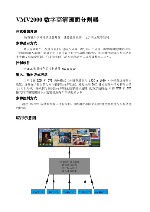
VMV2000数字高清画面分割器任意叠加漫游所有输入信号可以任意开窗,任意叠加漫游,无公共区域等限制。
多种显示方式显示方式几乎不受任何限制,包括八分屏、四分屏、二分屏、画中画和叠加窗口等。
它的每路输入都可在屏幕上的任意位置进行大小调整和定位,还可通过摇镜和变焦功能来突出某些特定区域。
它支持实时、动态地移动窗口以及调整窗口大小。
控制软件V-TECH独具特色的控制软件 MultiView输入、输出方式灵活用户可在 RGB 和 DVI 两种格式(分辨率最高为 1920 x 1080 )中任意选择输出设置,这确保了输出信号可与任何显示屏匹配,通过采用 DVI 格式的输入信号和输出信号,可以形成一条从信号源到显示屏的全数字信号通路,更为方便的是,可将 RGB 和 DVI 格式的双路输出信号分别输出至两个单独的显示器。
多种控制方式通过 RS-232 或以太网端口进行控制,图形化界面可以轻松地设置并进行所有功能的控制。
应用示意图特性⏹紧凑型3U机箱⏹多种输入信号任意选择⏹支持最大分辨率1920×1200,60Hz⏹四分、六分屏显示屏,最多可达八分屏,具有标题功能⏹画面淡入淡出功能⏹多种显示和窗口模式⏹多种控制方式:以太网、串口MVM系列多画面分割器为紧凑型3RU 机箱,可以对信号平稳调整位置和大小,并将其调整为任意长宽比。
可以在VGA、DVI、YCbCr/YPbPr、CVBS等多种输入信号中任意先择,以每种信号偶数的倍数为原则选册。
四分屏显示屏,具有标题功能。
插卡式设计结构配置灵活,扩容方便,稳定稳定性高易维护。
应用方案图技术规格。
浅谈高清画面分割处理技术及应用(北京科思图科技有限公司技术支持部)1.高清画面分割处理概述图1 典型的高清画面分割处理应用在安防监控、高清视频会议、广播画面监看、科研数据显示等许多高清视频应用场合,需要对高清画面进行分割处理,即在一个高清显示屏幕上显示来自多个视频源的高清视频信号。
这项工作通常由高清画面分割器(MultiView)来完成。
高清画面分割器(MultiView)通常有4分割、9分割、16分割几种,可以在一台显示屏幕上同时显示4、9、16个视频源的图像。
四分割是最常用的设备之一,其性能价格比也较好,图像的质量和连续性可以满足大部分要求。
九分割和十六分割价格较贵,而且分割后每路图像的分辨率和连续性都会下降,录像效果不好。
另外还有六分割、八分割、双四分割设备,但图像比率、清晰度、连续性并不理想,市场使用率很低,大部分高清画面分割器除了可以同时显示图像外,也可以显示单幅画面,还具有迭加时间和字符,进行画面变换、动画融合等不同功能。
2.高清画面分割处理技术介绍高清画面分割器(MultiView)的基本工作原理为:采用图像压缩和数字化处理的方法,把多个画面按同样的比例压缩在一个显示终端的屏幕上。
下图所示为高清画面分割器硬件组成原理图,主要包括视频解码芯片、数字信号处理、视频编码芯片、控制接口电路、大容量高速缓存等几大部分。
图2 高清画面分割器硬件组成原理图高清画面分割器硬件组成中,核心部件为数字信号处理器。
数字信号处理包含了专业级高速图像处理功能。
由于各通道视频数据流数据带宽大,数据一般采用多芯片进行并行处理,这样才能满足分割合并后单路输出的高分辨率显示,使得高速运动画面无撕裂,不丢帧,无图像追赶现象。
下图所示为高清画面分割器硬件外观图,图中带有散热器的部分即为并行的数字图像处理芯片。
图3 高清画面分割器硬件外观高清画面分割器硬件主要技术特点如下:1)纯硬件结构、稳定性高:设备一般采用纯硬件结构,无操作系统,启动时间短,无板卡式处理器死机、蓝屏和病毒的困扰,无系统崩溃风险,可全年持续工作。
SDI-MV User ManualVer 1.3 5/2014IndexFeature (3)Package Contents (4)Install Diagram (4)Front Panel (5)Rear Panel (6)Display Mode (7)Specifications (8)RS485 Commands (10)Firmware Upload (15)Update List (17)Feature●Allow up to four different SDI sources to be display in multiplex style in one monitor ●Independent scaling with anti-aliasing●Supports HD formats:⏹720p50 & 60⏹1080i50 & 60⏹1080p24, 25, 30, 50 & 60●Support 525i & 625i SD D1 format●Support up to 7.1ch of audio output●Auto 3G/HD/SD-SDI detection●HDMI 1.3 supported●SDI compliant outputs●D-Sub output●Firmware is upgradable in the field using the integrated USB port●The converter is Plug-and-PlayPackage ContentsThe SDI MUX BOX package contains the following items:●User Manual x 1●DC Adapter x 1●SDI MUX Box 1Install DiagramFront Panel5 134 62Rear Panel7123456Display ModeDISPLAY MODEOne of each is Displayed on the full screen.Four Channels is Displayed on the full screen. Sound is muted.Main Channel is displayed on Left side windows at the same time as other channels are displayed on right side window. Sound is usually from the main channel only.Mainotherfrom the main channel only.One of each is sequence displayed on the full screen.DISPLAY MODEDisplay Channel 1 video and audio on the full screenDisplay ChannelDisplay Channel 3 video/audio and full screen windowDisplay ChannelSpecificationsRS485 Commands1 2 3 4RS485 connector of diagramFirmware Upload Firmware is upgradable in the field using the integrated USB portHow to Firmware upgrade:Step 1.Open Upload Firmware Program tools.exe and connect box to PC by USBCable.Step 2.Plug and un-plug “DC adapter” to power on/off the converter box (theconnection check status will be changed to “Connect”)Step 3.Plug and un-plug “DC adapter” again (the connection check status will bechanged to “Connected”) and Please click the Open File button to select thefirmware bin file.Step 4.Please click “Start’ Button to proceed with new firmware programming. The PASS message will appear when the procedures finished.Step 5.Close Upload Firmware Program toolsUpdate List。
USER MANUALDesigned and Manufactured in the USA 1-800-284-2131OVERVIEWINTRODUCTION______________________________________________________________________________FEATURES___________________________________________________________________________________WHAT’S IN THE BOX?________________________________________________________________________TECHNICAL SPECIFICATIONS________________________________________________________________OPERATION CONTROLS AND FUNCTIONS___________________________________________________REMOTE CONTROL__________________________________________________________________________RS232 CONTROL_____________________________________________________________________________NETWORK CONTROL________________________________________________________________________SAFETY INSTRUCTION_______________________________________________________________________TROUBLESHOOTING_________________________________________________________________________TECHNICAL SUPPORT________________________________________________________________________LIMITED WARRANTY STATEMENT____________________________________________________________3334567-89-1213141415Thank you for purchasing this productSurge protection device recommendedFor optimum performance and safety, please read these instructions carefully before connecting, operating or adjusting this product. Please keep this manual for future reference.This product contains sensitive electrical components that may be damaged by electrical spikes, surges, electric shock, lighting strikes, etc. Use of surge protection systems is highly recommended in order to protect and extend the life of your equipment.IntroductionFeaturesThis product is a HDMI 2.0 Video Wall controller with 2 HDMI input, 2 HDMI loop out and 4 HDMI scaling out for video wall processing. With WEB UI and Remote Control to control the product for different wall display.• HDMI 2.0 and HDCP 2.2 compliant • Support multi-resolution up to 3840 x 2160 @ 60 Hz video output for video wall • Support 2 channels HDMI loop out • Support RS-232 and TCP/IP controlWhat’s in the box?Technical SpecificationsOperation Controls and Functions123REAR PANEL FRONT PANEL123456The EZW-UH4 supports IR control to manage inputs and video wall settings. Using the included remote, the instructions are as follows:The EZW-UH4 can be controlled via RS232 to manage input and video wall settings. Once connected to a PC, launch your preferred RS232 console. The baud rate connection will need to be set as 115200 bps. If the RS232 connection is established before booting up the device, the UI should display the following:USING THE MENUThe help menu can be displayed by sending the “//?” command which will prompt the following:RS232 CONTROL (continued)All menu commands must be sent with “//” followed by the appropriate command.CHART KEY(m) - Output number (1-4)(n) - Input number (1-2)(z) - Resolution option (1-2)NETWORK CONTROLThe EZW-UH4 can also be controlled via IP to manage input and video wall settings. T o find the IP, visit our website at https:///helpful-links/. Download and open the IP-Finder 2 software. Once launched, click on “Search Device”. This will display the device under Device IP. Use the IP displayed on your IP-Finder 2 on your preferred web browser. We highly recommend Google Chrome for the best compatibility.NETWORK CONTROL (continued)The EZW-UH4 will have several pages of navigation: Matrix Switch, TV Wall, and Settings. The default landing page will display the Matrix Switch page. TV Wall can be navigated by click on “TV Wall” on the top right side. Settings can be opened on the top left side with the triple lines in the purple box.The Matrix Switch page can be used to quickly change individual inputs and outputs for video, loop, and audio. Note: Loop Output 1 and Loop Output 2 only affect the Loop 2/MAIN output. Loop 1 will always display Input 1.The TV Wall page can be used to stitch the video outputs to create video walls within a 2X2 dimension. This includes 1X2, 2X1, or 2X2. Simply click on the desired input, draw over the grid area and click save selection. The cyan highlighted boxes will indicate the area that will be used for the new stitching. Clear selection will remove all stitching already set; this will allow new stitching to be created.Opening settings allows for the resolution to be changed or open configuration settings.The Configuration page allows for the EZW-UH4 to update its method for receiving its IP. The IP can be set as DHCP (default) or as Static. The login credentials can also be modified on this page as well. Note: Please select Save and Restart after making any changes. If updating IP, select the Save and Restart under the IP settings. If updating login credentials, select the Save and Restart under the user-name and password field.safety instructionT o ensure reliable operation of this product as well as protecting the safety of any personusing or handling this device while powered, please observe the following instructions.1. Do not operate either of this product outside the specified temperature and humidity range givenin the above specifications.2. Ensure there is adequate ventilation to allow this product to operate efficiently.3. Repair of the equipment should only be carried out by qualified professionals as these productscontain sensitive devices that may be damaged by any mistreatment.4. Only use this product in a dry environment. Do not allow any liquids or harmful chemicals to comeinto contact with these productsTroubleshootingTechnical supportNo Power • Make sure that the power adapter is securely connected to the power connector of the unit.• Check the output voltage of the power supply and make sure that the voltage value is around 12VDC.• Replace the power supply.No Video • Check if all the video cables are connected properly.• Connect the computer directly to the monitor to verify that your monitor and computer are functioning properly.• Restart the computers.Keyboard is not working • Check if the keyboard is properly connected to the unit.• Check if the USB cables connecting the unit and the computers are properly connected.• Try connecting the USB on the computer to a different port.• Make sure that the keyboard works when directly connected to the computer.• Replace the keyboard.Mouse is not working • Check if the mouse is properly connected to the unit.• Try connecting the USB on the computer to a different port.• Make sure that the mouse works when directly connected to the computer.• Replace the mouse.No Audio • Check if all the audio cables are connected properly.• Connect the speakers directly to the computer to verify that the speakers and the computer audio are functioning properly.• Check the audio settings of the computer and verify that the audio output is through the speakers.For product inquiries, warranty questions, or technical questions, please contact *****************.Limited warranty statementA. Extent of limited warrantySmartAVI, Inc. warrants to the end-user customers that the SmartAVI product specified above willbe free from defects in materials and workmanship for the duration of 1 year, which duration begins on the date of purchase by the customer. Customer is responsible for maintaining proof of date of purchase.SmartAVI limited warranty covers only those defects which arise as a result of normal use of the product, and do not apply to any:a. Improper or inadequate maintenance or modificationsb. Operations outside product specificationsc. Mechanical abuse and exposure to severe conditionsIf SmartAVI receives, during applicable warranty period, a notice of defect, SmartAVI will at its discretion replace or repair defective product. If SmartAVI is unable to replace or repair defective product covered by the SmartAVI warranty within reasonable period of time, SmartAVI shall refund the cost of the product.SmartAVI shall have no obligation to repair, replace or refund unit until customer returns defective product to SmartAVI.Any replacement product could be new or like new, provided that it has functionality at least equal to that of the product being replaced.SmartAVI limited warranty is valid in any country where the covered product is distributed by SmartAVI.B. Limitations of warrantyT o the extant allowed by local law, neither SmartAVI nor its third party suppliers make any other warranty or condition of any kind whether expressed or implied with respect to the SmartAVI product, and specifically disclaim implied warranties or conditions of merchantability, satisfactory quality, and fitness for a particular purpose.C. Limitations of liabilityT o the extent allowed by local law the remedies provided in this warranty statement are the customers sole and exclusive remedies.T o the extant allowed by local law, except for the obligations specifically set forth in this warranty statement, in no event will SmartAVI or its third party suppliers be liable for direct, indirect, special, incidental, or consequential damages whether based on contract, tort or any other legal theory and whether advised of the possibility of such damages.D. Local lawT o the extent that this warranty statement is inconsistent with local law, this warranty statement shall be considered modified to be consistent with such law.NOTICEThe information contained in this document is subject to change without notice. SmartAVI makes no warranty of any kind with regard to this material, including but not limited to, implied warranties of merchantability and fitness for particular purpose. SmartAVI will not be liable for errors contained herein or for incidental or consequential damages in connection with the furnishing, performance or use of this material. No part of this document may be photocopied, reproduced, or translated into another language without prior written consent from SmartAVI, Inc.20180109Designed and Manufactured in the USAT el: (800) AVI-2131 • (702) 800-00052455 W Cheyenne Ave, Suite 112North Las Vegas, NV 89032。
图 1 Pengtagon™五进一出多画面处理器外观图图 2 1M DP to DP线缆(选配)图3 1M DVI 双通道(dual link)线缆(选配)图 4 YPbPr与BNC转接头(选配)图 5 直通串口线视频处理采用大视独有的FlexView采用纳米级半导体工艺,可对高清视频信号进行全帧速实时无失真处理。
目前采用最高系列芯片,可以轻松满足市场的需求。
DVI-M接口,支持4路分辨率超高清动态底图Displayport1.1a表1所支持的输入信号图8 与融合机的连接系统图投影融合最终显示画面如下图:图10 与多屏宝的连接系统图图11 使用多台多屏宝的开窗效果图4.2 控制软件操作流程4.2.1软件功能描述拼接器软件主要实现了四路输入一路输出,而且输出为一个大的完整背景画面(背景色彩可自定义,默认纯黑),输入的各路信号以窗口的形式显示在背景画面上。
主要功能有:(1)设备功能区(2)信号源状态区(3)开窗操作区图12 软件初始画面软件界面,整体分为3个区域。
设备功能区(主要功能项如:设备场景,连接设备,背景属性,窗口属性,视频属性,图像切割等)信号源状态区,软件界面左边区域。
主要标记了当前信号是否接入了信号源以及接入信号源的类型。
开窗操作区,软件右边最大的灰色区域,我们对窗口的基本所有操作都在这里完成。
(1)选择网络连接,填写设备IP(2)点击“连接”设备默认网络参数,连接设备成功后,可以通过点击“修改”,改变设备的网络参数图13网络通信连接界面设备默认的IP地址: 192.168.1.200,可根据设备实际的IP地址设置,点击“连接”进行设备连接。
输入端4为HDMI输入当前仅一个子窗口显示图14连接成功界面–主操作界面信号源窗口管理区域及状态区域显示了设备当前状态,如图15所示,此状态为设备连接后载入的之前工作的状态显示当前窗口的布局,默认情况下没有子窗口;(1)选择COM 口,连接设备(2)修改网络参数(3)点击“修改”,设备重启生效图 15修改网络参数操作设备窗口标示/名称点击“确定”,即创建成功窗口标示:窗口的ID,顺序自动生成窗口大小位置信号源:当前窗口的输入源叠放序号:层次关系,1-最底层、4最上层还原窗口关闭此窗口窗口对齐窗口最大化窗口还原:还原到上次窗口所在位置与大小窗口最大化:窗口占满整个输出屏窗口对齐:窗口横跨几个虚拟/逻辑区,对齐到整个区域图17子窗口自带按键功能从左到右四个按钮功能一次为:逻辑对齐按钮,最大化按钮,还原按钮,关闭按钮。
MV-X Multiviewer 高清多画面处理器使用手册安全注意事项注意:手册中所列为出版之前时的信息,制造商保留更改和改进其产品的权利,所有参数如有更改,恕不通知安装场所为了确保设备使用安全并且获得满意的性能,在安装设备时,需要考虑下述情况:1.远离高温的热源和环境。
2.避免阳光直接照射。
3.为了确保设备的正常散热,应避开通风不良的场所切勿堵塞设备的通风口。
此款设备上盖和两侧有通风口,在安装时,其后部两侧应距离其他设备或墙壁5CM以上以利于散热。
4.本设备应水平安装。
5.避免安装后会剧烈震动的场所。
6.避免在过冷、过热的场所间相互搬动机器,以免设备内部产生结露,影响机器的使用寿命。
7.切忌勿用湿手触摸电源和机器。
8.勿将液体溅落在设备上,以免造成设备内部短路或失火。
9.勿将其它设备直接放置于本机上部。
10.在工程安装时请连接好地线,以免造成雷击主芯片损坏。
11.设备有故障时,为了避免损坏,请勿自行拆开机壳,必须委托有资格的专业维修人员在指定的维修单位进行维修。
12.为了防止电击和失火,请勿将本机器放置到雨淋或潮湿的场所。
在使用前请阅读和研究此手册中的所有指示和注意事项!此手册和原有销售单据保留,以便将来必要的维修时之用。
拆开包装后,检查是否遗失或损坏如果发现任何遗失或损坏,请不要安装或操作此产品,应尽快同代理商联系。
1.概述MV-X 高清多画面处理器是专业化的图形处理与控制设备,它将多路图像信号合成一路高清信号输出。
MV-X高清多画面处理器采用专用图像处理芯片,嵌入式插卡结构,一卡一路,内嵌专用操作系统,整个系统封闭式运行。
MV-X高清多画面处理器器可接受CVBS、VGA、HDMI(DVI)、YPbPr 或SDI 等格式的视频信号,并按用户要求对视频信号进行视窗大小、显示位置、图像比例等方面的调整和变换,最终输出统一格式的图像信号。
2.性能特点(1)输入最多支持16路,一卡一路,6路以下(含)1U标准机箱,6路以上4U标准机箱;(2)内部图像处理全程10-bit处理,色彩还原真实;(3)输入支持CVBS,VGA,YPbPr,HDMI(DVI)和SDI信号,最高分辨率到1920x1200@60Hz。
(VGA和YPbPr,SDI和CVBS分别共享一个接口);(4)输出支持VGA、YPbPr、HDMI(DVI)和SDI,最高分辨率到1920x1200@60Hz;(5)模拟输入ADC最高采样频率205Mhz,支持到UXGA@75Hz/WUXGA60Hz,支持Composite-Sync和Sync-on-Green(SOG);(6)H DMI输入兼容HDMI1.3,支持HDCP1.2,Deep color:12-bit YCC4:4:4,XVYCC支持基于IEC61966-2-4彩色标准;(7)C VBS输入集成高级3D自适应梳状滤波器和去隔行处理,自动PAL,NTSC制式识别;(8)S DI输入支持3G/HD/SD-SDI,速率143Mbps~2.97Gbps,兼容SMPTE 259M、292M、344M、424M、ITU R BT.601、ITU R BT.1120 串行视频标准;(9)Y PbPr输入内建自适应3D/TNR Noise Reduction,De-interlacing到1080i,集成自动对比度控制和图像边缘平滑处理;(10)支持本机按键和红处遥控器快速操作;(11)支持电脑软件控制,用户可自任意拉伸,拖动窗口,可定制画面模式下载到设备中通过按键快速切换画面模式;(12)支持断电现场保护(通过菜单设置);3.技术参数4.设备操作(1)设备的前视图和后视图分别如下(6画面):①DISPLAY:液晶显示窗,显示工作状态;②IR:红外遥控窗口;③KEYBOARD:操作按键,1~6选择单画面,MODE选择画面模式SOURCE/MEMU轻按选择视频源,长按2S放开选择设备菜单。
①每通道一卡,每个卡是相同的,可互换。
②CVBS/SDI共用BNC接口,默认是CVBS输入,SDI输入需订货要求。
③VGA/YPbPr共用DB15接口,默认是VGA输入,YPbPr输入需订货要求。
④HDMI/DVI OUT是HDMI TYPE A接口。
VGA/YPbPr OUT是DB15接口。
⑤每块卡有LED,上电是红色,运行正常后绿色闪烁,如果锁定输入视频源,绿灯常亮。
⑥RS232接控制电脑。
(2)画面模式切换轻按数字键1~6选择指定的单画面全屏显示。
液晶窗显示“Chx Full:HDMI”(x=1~6),后面显示当前通道的视频源。
轻按“MODE”切换画面模式,液晶窗显示模式号。
如果没有通过电脑控制软件定制模式,只有一个多画面模式显示(6画面是3x2模式,4画面是2x2模式)。
用户可通过控制软件创建自定义的画面模式存在设备中,通过“MODE”键快速的切换画面模式,最多可创建15个画面模式。
(3)切换视频源先选择单画面模式,再轻按“SOURCE/MEMU”键,每按完一次需等待2S,默认的视频源循环顺序是HDMI -> VGA -> YPbPr -> CVBS。
(4)更改输出分辨率常按“SOURCE/MEMU”键2S放开,液晶窗显示“Press 1 ->Menu”,再轻按“1”键进入菜单设置,液晶窗显示当前的输出分辨率,要改变输出分辨率轻按“4”键,选择好分辨率后再轻按“SOURCE/MEMU”退出。
(5)保存画面模式出厂默认不保存断电前的画面模式,如果要保存断电前的画面模式,常按“SOURCE/MEMU”键2S放开,液晶窗显示“Press 1 ->Menu”,再连续轻按“1”,直到显示“Save Mode:NO”,再轻按“4”,显示“Save Mode:Yes”,再轻按“SOURCE/MEMU”键退出。
下次设备开机时就会显示断电前的画面模式。
(6)更改设备ID此设备ID只用于和电脑通讯时识别设备,出厂默认为“1”,如果多台设备用同一台电脑控制时,每台设备的ID应该不一样,要改变设备ID,常按“SOURCE/MEMU”键2S放开,液晶窗显示“Press 1->Menu”,再连续轻按“1”,直到显示“Device ID:01”,再轻按“3”或“4”改变ID,最后按“SOURCE/MEMU”退出。
(7)恢复出厂设置此功能只用出厂调试时使用。
常按“SOURCE/MEMU”键2S放开,液晶窗显示“Press 1 ->Menu”,再连续轻按“1”,直到显示“Restore factory”,再轻按“4”,再轻按“SOURCE/MEMU”退出,等待3秒后重新开关机设备。
如果输入是VGA或YPbPr,需要重新做ADC calibration。
(8)A DC Calibration如果没有做ADC Calibraion,画面显示很暗,此功能只对VGA和YPrPr输入有效,用于对模拟输入通道的亮度、对比度、色度自动校准。
设备出厂时已经做过Calibration,如果使用了“恢复出厂设置”,就需要重新对VGA和YPBPR输入源Calibration。
Calibraion之前,必须接入稳定的VGA或YPBPR视频源,常按“SOURCE/MEMU”键2S放开,液晶窗显示“Press 1 ->Menu”,再轻按“1”,直到显示“VGA Calibration”,再轻按“4”,画面会闪动一下再正常显示。
(9)C YC Running开/关画面模式自动偱环显示功能。
此功能需和计算机软件配合使用,只有通过计算机软件设置好画面模式和偱环时间后才有效。
首先通过计算机软件下载用户自定义的画面模式,总共能存储15个画面模式。
再设置“模式自动偱环”的时间,最长255秒。
开启模式偱环显示后,可脱开计算机按预设的时间间隔显示用户自义的画面模式。
如要通过本机菜单关闭自动偱环显示,常按“SOURCE/MEMU”键2S放开,液晶窗显示“Press 1 ->Menu”,再连续轻按“1”,直到显示“CRC Running: ON”,再轻按“4”,显示“CRC Running: OFF”。
再轻按“SOURCE/MEMU”退出。
(10)Startup Logo允许/禁止开机画面显示,默认开机先显示“Multiview”。
如果要关闭,常按“SOURCE/MEMU”键2S放开,液晶窗显示“Press 1 ->Menu”,再连续轻按“1”,直到显示“Startup Logo: ON”,再轻按“4”,显示“Startup Loog: OFF”,再轻按“SOURCE/MEMU”退出。
5.软件安装运行安装程序setup.exe,自动安装软件到默认目录下,安装程序会在桌面自动生成快捷方式MultiView.exe,双击快捷方式图标即可启动应用程序。
6.软件操作(1)运行软件软件启动后,进入运行主界面,如下图:如果是第一次运行本软件需要先选择连接计算机和MV-X设备的串口,点击菜单中的“设置”弹出如下对话框:选择本机正确的串口后按“确认”返回。
如果串口选择错误或者没有正确连接终端设备,可能导致通讯失败软件启动后会在软件视窗口显示四(或者六)个模拟窗口,来模拟终端画面窗口,如下图:用鼠标拖动、拉伸窗口可以实现画面的尺寸缩放和位置移动。
(2)连接设备单击左下方的“连接设备”按钮,等待大约三秒后,如果通讯失败,软件会弹出失败信息提示框。
此时软件会自动进入演示模式,在演示模式下,串口将不发送控制指令,但其他操作功能和正常连接模式没有区别。
演示模式下要重新连接终端设备,需要关闭软件,连接好设备后,重新启动控制软件。
如果连接设备成功弹出如下图对话框:对话框会显示设备的基本信息,包括设备通道数、输出分辨率、当前显示模式和用户自定画面模式数量。
点击“确认”,软件界面会自动更新保持和设备同步。
(3)控制面板设备连接成功后,软件左侧控制面板如下图(以4画面为例):置三个部分。
⊙设备地址:如果多台机器级联时,可以通过“设备地址”下拉框选择要操作的设备地址号。
如果要修改设备地址需在设备端通过菜单修改(见前文 4.6),软件端不可以修改终端设备地址。
设备出厂时默认地址为1。
⊙设备类型:MV-2,MV-4,MV-6,MV-8,MV-9…⊙输出分辨率:下拉框可以修改设备的输出分辨率。
⊙通道:下拉框选择要操作通道号,然后可对该通道切换信号源(固定信号源的设备除外)、显示或隐藏,手动设置图像尺寸等。
⊙信号源:针对混合信号源的设备,每个通道都可有CVBS,HDMI,VGA,YPBPR,SDI输入源可选择。
当信号源选择为VGA或YPBPR输入时,ADC校准按钮有效,此功能同设备菜单中的ADC Calibration(参见前文4.8)。