307475智能天线
- 格式:ppt
- 大小:556.00 KB
- 文档页数:26
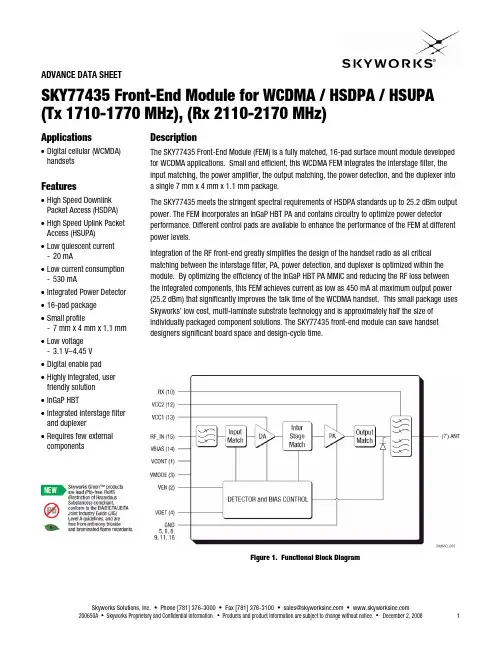
ADVANCE DATA SHEETSKY77435 Front-End Module for WCDMA / HSDPA / HSUPA (Tx 1710-1770 MHz), (Rx 2110-2170 MHz)Applications •Digital cellular (WCMDA) handsetsFeatures•High Speed Downlink Packet Access (HSDPA) •High Speed Uplink Packet Access (HSUPA)•Low quiescent current-20 mA•Low current consumption -530 mA •Integrated Power Detector •16-pad package •Small profile-7 mm x 4 mm x 1.1 mm •Low voltage-3.1 V–4.45 V •Digital enable pad •Highly integrated, user friendly solution •InGaP HBT •Integrated interstage filter and duplexer •Requires few external componentsDescriptionThe SKY77435 Front-End Module (FEM) is a fully matched, 16-pad surface mount module developed for WCDMA applications. Small and efficient, this WCDMA FEM integrates the interstage filter, the input matching, the power amplifier, the output matching, the power detection, and the duplexer into a single 7 mm x 4 mm x 1.1 mm package.The SKY77435 meets the stringent spectral requirements of HSDPA standards up to 25.2 dBm output power. The FEM incorporates an InGaP HBT PA and contains circuitry to optimize power detector performance. Different control pads are available to enhance the performance of the FEM at different power levels.Integration of the RF front-end greatly simplifies the design of the handset radio as all critical matching between the interstage filter, PA, power detection, and duplexer is optimized within the module. By optimizing the efficiency of the InGaP HBT PA MMIC and reducing the RF loss between the integrated components, this FEM achieves current as low as 450 mA at maximum output power (25.2 dBm) that significantly improves the talk time of the WCDMA handset. This small package uses Skyworks’ low cost, multi-laminate substrate technology and is approximately half the size of individually packaged component solutions. The SKY77435 front-end module can save handset designers significant board space and design-cycle time.Figure 1. Functional Block DiagramADVANCE DATA SHEET SKY77435 FRONT-END MODULE FOR WCDMA/HSDPA/HSUPATx (1710-1770 MHz), Rx (2110-2170 MHz)Electrical SpecificationsThe following tables list the electrical characteristics of the SKY77435 Front-End Module for WCDMA. Table 1 lists the absolute maximum ratings and Table 2 specifies therecommended operating conditions necessary to achieve the electrical performance listed in Table 3. Table 4 through Table 7 defines the standard test configurations for WCDMA, HSDPA, and HSUPA modes. Table 8 provides specifications for PowerDetection. Table 9 and Table 10 specifies the Nominal Duplexer Performance for Band IV and Band X, respectively..Table 1. Absolute Ratings 1Parameter Symbol Minimum Nominal Maximum U nitRF Input Power P IN — — 10.0 dBm No RF —3.46.0VoltSupply VoltagesWith RFV CC1, V CC2, V BIAS— 3.4 4.7 VoltBias Control Voltage V CONT — — 2.7 VoltMode Control Voltage V MODE — — 3.0 VoltsEnable Control Voltage V EN — — 3.0 VoltOperating T CASE –20 +25 +110 TemperaturesStorage T STG –55 — +125°C 1 No damage assuming only one parameter at a time is set to limit with all other parameters set at nominal values.Table 2. Recommended Operating ConditionsParameter Symbol Minimum Nominal Maximum U nitTx Channel Center Frequency F T X 1712.4 1740.0 1767.6 MHz Rx Channel Center Frequency F R X = F T X + 400 MHz2112.42140.02167.6MHzV CC1, V CC2 3.1 1 3.4 4.45 Supply VoltagesV BIAS 3.1 3.4 4.45Volt Bias Control Voltage V CONT 0.5 — 1.9 VoltLow Power Mode (LPM) V MODE_L 1.5 1.8 2.85 Mode ControlHigh Power Mode (HPM)V MODE_H 0.0 0.0 0.56Volt Disabled V EN_L 0.0 0.0 0.56 Enable Control Setting EnabledV EN_H 1.5 1.8 2.85Volt Operating TemperatureT CASE –20 +25 +85 °C1 For V CC < 3.4 V, maximum output power = P MAX2SKY77435 FRONT-END MODULE FOR WCDMA/HSDPA/HS U PA ADVANCE DATA SHEETTx (1710-1770 MHz), Rx (2110-2170 MHz)Table 3. Electrical Specifications for Nominal Operating Conditions 1Parameter Symbol Conditions Minimum Typical Maximum U nitP MID HPM, LPMV CC ≥ 3.1 V 10.0 — — P MAX2 HPMV CC ≥ 3.1 V 24.4 — — Linear Output PowerP MAX1 HPM25.2——dBm Mid Power G MID LPMP MID 11.0 — 23.0 GainHigh Power G HIGHV CC = 3.4 V P MAX1T CASE = 25 °C 19.5 — 28.5dB Gain Flatness Over Frequency ΔG PWR Each Tx Frequency –2.5 — 2.5 dBMid Power LPM P MID— — 50Band IV High PowerP MAX1 — — 530 Mid PowerLPMP MID— — 50Current ConsumptionBand X High PowerI CCP MAX1 —— 530 mA Mid Power PAE_MID LPMP MID5.4 — —Band IV High Power PAE_HIGHP MAX1 18.4 — —Mid Power PAE_MID LPM P MID5.4 — —Power Added EfficiencyBand X High Power PAE_HIGHP MAX1 18.4 — —% Error Vector MagnitudeEVM — 5 % 5 MHz ACL1 —–40—Adjacent Channel Leakage Ratio 210 MHzACL2—— –54 —dBcSecond 2f O — — –33 Harmonic SuppressionThird 3f OP MAX1 — — –33 dBm NRx1 P MAX1869–894 MHz RBW = 3.84 MHz — — –61 NRx2 P MAX11575.42 MHz RBW = 2.046 MHz — — –100NRx3 P MAX11930–1990 MHz RBW = 3.84 MHz — — –61NRx4 P MAX12110–2170 MHz RBW = 3.84 MHz — — –114Tx Noise Power in Rx BandNRx5 P MAX12400–2483.5 MHz RBW = 1.0 MHz— — –90dBmADVANCE DATA SHEET SKY77435 FRONT-END MODULE FOR WCDMA/HSDPA/HSUPATx (1710-1770 MHz), Rx (2110-2170 MHz)Table 3. [continued] Electrical Specifications for Nominal Operating Conditions 1MaximumU nit Parameter Symbol Conditions MinimumTypicalInput Voltage Standing Wave Ratio VSWR — — — 2:118mA—Quiescent Current I CQ — —mA1—Control Current I BA ——mA1——Digital Enable Current I EN —— — 20 μALeakage Current I LEAK V CC1, V CC2, V BIAS = 4.45 VV CONT = 0 VV EN = 0.2 VV MODE_H = 0 VStability (spurious output) S 8:1 VSWR, all phases — — –65 dBc10:1——Ruggedness 3 Ru—1Unless otherwise specified: V CC = 3.4 V, Temp. = 25 °C.2For STC1 WCDMA, STC2 HSDPA, and STC3 HSUPA modes test conditions. For STC4 HSUPA, power back off = 2.6 dB.3ACLR is specified per 3GPP as the ratio of in-band power to adjacent power, both measured in 3.84 MHz bandwidth at specified offsets.4All phases, time = 10 seconds, continuous WCDMA/HSDPA modulated signal.Table 4. Standard Test Configuration – STC1 WCDMA ModeParameter Level Spread Code Spread Factor I/Q βc βd βhs βec βed Relative Power (dB)kbps 0 256 Q 8/15 — — — — –6.547DPCCH 15kbps 16 64 I — 15/15 — — — –1.087DPDCH 60Table 5. Standard Test Configuration – STC2 HSDPA ModeParameter Level Spread Code Spread Factor I/Q βc βd βhs βec βed Relative Power (dB)kbps 0 256 Q 12/15 — — — — –7.095DPCCH 15kbps 16 64 I — 15/15 — — — –5.157DPDCH 60kbps 64 256 Q — — 24/15 — — –3.01215HS-DPCCHTable 6. Standard Test Configuration – STC3 HSUPA ModeParameter Level Spread Code Spread Factor I/Q βc βd βhs βec βed Relative Power (dB)kbps 0 256 Q 8/15 — — — — –19.391DPCCH 15DPDCH 960kbps 1 4 I — 15/15 — — — –13.931HS- DPCCH 15 kbps 64 256 Q — — 8/15 — — –19.391kbps 1 256 I — — — 10/15 — –17.338E-DPCCH 15kbps 2 4 I — — — — 71.5/15 –0.371E-DPDCH 960SHEETSKY77435 FRONT-END MODULE FOR WCDMA/HSDPA/HSDATAU PA ADVANCETx (1710-1770 MHz), Rx (2110-2170 MHz)Table 7. Standard Test Configuration – STC4 HSUPA ModeParameter Level Spread Code Spread Factor I/Q βc βd βhs βec βed Relative Power (dB)kbps 0 256 Q 6/15 — — — — –12.499DPCCH 15kbps 1 4 I — 15/15 — — — –4.540DPDCH 960HS- DPCCH 15 kbps 64 256 Q — — 2/15 — — –22.041kbps 1 256 I — — — 12/15 — –6.478E-DPCCH 15kbps 2 4 I — — — — 15/15 –4.425E-DPDCH 960Table 8. Electrical Specifications for Power DetectorTx Power DetectionU nitMaximumTypicalCharacteristic Symbol Conditions MinimumdBm26.2Power Detect Range P DET0.0—Detector Output Range V DET 3 dBm ≤ P O ≤ 26.2 dBm 400 (rms) — 1800 (peak)mVTable 9. Nominal Duplexer Performance – Band IV7Antenna to Rx ParameterMaximumU nitTypicalCharacteristic Symbol Conditions MinimumInsertion Loss IL Rx2110 MHz…2170 MHz — — 2.5 dBRipple Each Rx Frequency –0.5 — 0.5 dB—dBAttenuation—DC (12750)MHz 20A R X1390 MHz…410 MHz 40 — —A R X2703 MHz…724 MHz 30 — —A R X31055 MHz…1085 MHz 45 — —A R X41310 MHz…1370 MHz 35 — —Tx Band A R X51710 MHz…1770 MHz 50 — —A R X61910 MHz…1970 MHz 25 — —Tx + Rx A R X73820 MHz…3940 MHz 35 — —2Tx + Rx A R X85530 MHz…5710 MHz 35 — —2.0:1—VSWR ——dBm—30Input ——Tx Power @ Rx Port 1710 MHz…1770 MHz— — –25 dBmP MAX1ADVANCE DATA SHEET SKY77435 FRONT-END MODULE FOR WCDMA/HSDPA/HSUPATx (1710-1770 MHz), Rx (2110-2170 MHz)Table 10. Nominal Duplexer Performance – Band X8Antenna to Rx ParameterU nitMaximum Characteristic Symbol Conditions MinimumTypicalInsertion Loss IL Rx2110 MHz…2170 MHz — — 2.8 dBRipple Each Rx Frequency –0.5 — 0.5 dBDC (12750)——AttenuationMHz 20dBA R X1390 MHz…410 MHz 40 — —A R X2703 MHz…724 MHz 30 — —A R X31055 MHz…1085 MHz 45 — —A R X41310 MHz…1370 MHz 35 — —Tx Band A R X51710 MHz…1770 MHz 50 — —A R X61910 MHz…1970 MHz 25 — —Tx + Rx A R X73820 MHz…3940 MHz 35 — —2Tx + Rx A R X85530 MHz…5710 MHz 35 — ——2.0:1—VSWR —30dBm—Input ——Tx Power @ Rx Port 1710 MHz…1770 MHz— — –25 dBmP MAX1SKY77435 FRONT-END MODULE FOR WCDMA/HSDPA/HS U PA ADVANCE DATA SHEETTx (1710-1770 MHz), Rx (2110-2170 MHz)Evaluation Board DescriptionThe evaluation board is a platform for testing and interfacingdesign circuitry. To accommodate the interface testing of the SKY77435, the evaluation board schematic and the basicassembly diagram are included for preliminary analysis and design. Figure 2 is a simple schematic of the board assembly in Figure 3.Figure 2. SKY77435 Evaluation Board Schematic DiagramFigure 3. SKY77435 Evaluation Board Assembly DiagramADVANCE DATA SHEET SKY77435 FRONT-END MODULE FOR WCDMA/HSDPA/HSUPATx (1710-1770 MHz), Rx (2110-2170 MHz)Package DimensionsThe SKY77435 is a multi-layer laminate base, overmoldencapsulated modular package designed for surface-mounted solder attachment to a printed circuit board. Figure 4 is amechanical drawing of the pad layout for this package. Figure 5provides a recommended phone board layout footprint for the FEM to help the designer attain optimum thermal conductivity, good grounding, and minimum RF discontinuity for the 50 ohmterminals.Figure 4. Dimensional Diagram for 7 x 4 x 1.1 mm, 6-Pad Package (All Views) – SKY77435SHEET SKY77435 FRONT-END MODULE FOR WCDMA/HSDPA/HSDATAU PA ADVANCETx (1710-1770 MHz), Rx (2110-2170 MHz)Figure 5. Phone PCB Layout Footprint for 7 x 4 mm, 16-Pad Package – SKY77435ADVANCE DATA SHEET SKY77435 FRONT-END MODULE FOR WCDMA/HSDPA/HSUPATx (1710-1770 MHz), Rx (2110-2170 MHz)Package DescriptionFigure 6 shows each pad name and the pad numberingconvention, which starts with pad 1 in the upper left, as indicated and increments counter-clockwise around the package. Figure 7illustrates typical case markings.Figure 6. SKY77435 16-Pad Configuration – (Top View)Figure 7. Typical Case Markings (Top View)Package Handling InformationBecause of its sensitivity to moisture absorption, this device package is baked and vacuum-packed prior to shipment. Instructions on the shipping container label must be followed regarding exposure to moisture after the container seal is broken, otherwise, problems related to moisture absorption may occur when the part is subjected to high temperature during solder assembly.The SKY77435 is currently qualified for MSL3/260 °C. Care must be taken when attaching this product, whether it is done manually or in a production solder reflow environment. If the part isattached in a reflow oven, the temperature ramp rate should not exceed 3 °C per second; maximum temperature should notexceed 260 °C. If the part is manually attached, precaution should be taken to insure that the part is not subjected to temperatures exceeding 260 °C for more than 10 seconds. For details on attachment techniques, precautions, and handling procedures recommended by Skyworks, please refer to Skyworks Application Note: PCB Design and SMT Assembly/Rework, Document Number 101752. Additional information on standard SMT reflow profiles can also be found in the JEDEC Standard J–STD–020. Production quantities of this product are shipped in the standard tape-and-reel format. For packaging details, refer to Skyworks Application Note: Tape and Reel – RF Modules, Document Number 101568. Electrostatic Discharge Sensitivity (ESD)To avoid ESD damage, both latent and visible, it is very important that the product assembly and test areas follow the Class 1 ESD handling precautions listed below.• Personnel Grounding - Wrist Straps- Conductive Smocks, Gloves and Finger Cots - Antistatic ID Badges• Protective Workstation - Dissipative Table Top- Protective Test Equipment (Properly Grounded) - Grounded Tip Soldering Irons - Solder Conductive Suckers - Static Sensors• Facility- Relative Humidity Control and Air Ionizers - Dissipative Floors (less than 109 Ω to GND) • Protective Packaging and Transportation - Bags and Pouches (Faraday Shield)- Protective Tote Boxes (Conductive Static Shielding) - Protective Trays - Grounded Carts- Protective Work Order HoldersOrdering InformationModel Number Manufacturing Part Number Product Revision Package Operating Temperature SKY77435 SKY77435 MCM 4 x 7 x 1.1 mm –20 °C…+85 °CRevision HistoryRevision Date DescriptionA December 2, 2008 Initial Release – Advance InformationReferencesSkyworks Application Note: Tape and Reel – RF Modules, Document Number 101568Skyworks Application Note: PCB Design and SMT Assembly/Rework, Document Number 101752JEDEC Standard J–STD–020© 2008, Skyworks Solutions, Inc. All Rights Reserved.Information in this document is provided in connection with Skyworks Solutions, Inc. (“Skyworks”) products or services. These materials, including the information contained herein, are provided by Skyworks as a service to its customers and may be used for informational purposes only by the customer. Skyworks assumes no responsibility for errors or omissions in these materials or the information contained herein. Skyworks may change its documentation, products, services, specifications or product descriptions at any time, without notice. Skyworks makes no commitment to update the materials or information and shall have no responsibility whatsoever for conflicts, incompatibilities, or other difficulties arising from any future changes.No license, whether express, implied, by estoppel or otherwise, is granted to any intellectual property rights by this document. Skyworks assumes no liability for any materials, products or information provided hereunder, including the sale, distribution, reproduction or use of Skyworks products, information or materials, except as may be provided in Skyworks Terms and Conditions of Sale.THE MATERIALS, PRODUCTS AND INFORMATION ARE PROVIDED “AS IS” WITHOUT WARRANTY OF ANY KIND, WHETHER EXPRESS, IMPLIED, STATUTORY, OR OTHERWISE, INCLUDING FITNESS FOR A PARTICULAR PURPOSE OR USE, MERCHANTABILITY, PERFORMANCE, QUALITY OR NON-INFRINGEMENT OF ANY INTELLECTUAL PROPERTY RIGHT; ALL SUCH WARRANTIES ARE HEREBY EXPRESSLY DISCLAIMED. SKYWORKS DOES NOT WARRANT THE ACCURACY OR COMPLETENESS OF THE INFORMATION, TEXT, GRAPHICS OR OTHER ITEMS CONTAINED WITHIN THESE MATERIALS. SKYWORKS SHALL NOT BE LIABLE FOR ANY DAMAGES, INCLUDING BUT NOT LIMITED TO ANY SPECIAL, INDIRECT, INCIDENTAL, STATUTORY, OR CONSEQUENTIAL DAMAGES, INCLUDING WITHOUT LIMITATION, LOST REVENUES OR LOST PROFITS THAT MAY RESULT FROM THE USE OF THE MATERIALS OR INFORMATION, WHETHER OR NOT THE RECIPIENT OF MATERIALS HAS BEEN ADVISED OF THE POSSIBILITY OF SUCH DAMAGE.Skyworks products are not intended for use in medical, lifesaving or life-sustaining applications, or other equipment in which the failure of the Skyworks products could lead to personal injury, death, physical or environmental damage. Skyworks customers using or selling Skyworks products for use in such applications do so at their own risk and agree to fully indemnify Skyworks for any damages resulting from such improper use or sale.Customers are responsible for their products and applications using Skyworks products, which may deviate from published specifications as a result of design defects, errors, or operation of products outside of published parameters or design specifications. Customers should include design and operating safeguards to minimize these and other risks. Skyworks assumes no liability for applications assistance, customer product design, or damage to any equipment resulting from the use of Skyworks products outside of stated published specifications or parameters. Skyworks, the Skyworks symbol, “Breakthrough Simplicity,” DCR, Helios, HIP3, Innovation to Go, Intera, iPAC, LIPA, Polar Loop, and System Smart are trademarks or registered trademarks of Skyworks Solutions, Inc., in the United States and other countries. Third-party brands and names are for identification purposes only, and are the property of their respective owners. Additional information, including relevant terms and conditions, posted at , are incorporated by reference.。

美国爱瑞通信公司展示智能天线技术
佚名
【期刊名称】《中国无线通信》
【年(卷),期】2001(007)009
【总页数】1页(P49)
【正文语种】中文
【中图分类】F416.63
【相关文献】
1.智能天线技术释放宽带潜力——解析美国爱瑞通信公司Intellicell技术 [J],
2.做频谱文章走技术提供新路——访美国爱瑞通信公司张斌先生 [J],
3.智能天线为3G加速--访美国爱瑞通信公司战略业务拓展副总裁张彬先生 [J], 晓寒
4.创现代管理体系树"爱瑞"企业品牌--上海爱瑞系统集成有限公司第二次创业目标[J], 方卫
5.美国模拟器件公司的TigerSHARC处理器被爱立信选中用于3G基站的开发——软件可编程的TigerSHARC ADSP-TS201处理器为3G WCDMA基带通信平台的可扩缩能力和灵活的功能升级准备了条件 [J],
因版权原因,仅展示原文概要,查看原文内容请购买。


•Wireless application – ISM band, including WiFi / Bluetooth •High density applications•Bluetooth headsets or ear pieces •Computer mouse and keyboards •PROFINET – Industrial automation •Video Game systems•Alternative to larger PCB solutionFEATURES:APPLICATIONS:•2470MHz, Bandwidth ≥200MHz •Suitable for RoHS compliant reflow •Gain 2.6dBi (Peak) / 0.7dBi (Average)•VSWR <2:1•Small size – 7.0 x 2.0 x 1.0mm (0.275 x 0.078 x 0.039inch)•Non Ground Mounting type.•Power Handling 3W Max •Matched to 50 OhmSTANDARD SPECIFICATIONSMaximum RatingsElectrical Characteristics5101 Hidden Creek Lane Spicewood TX 78669Phone: 512-371-6159 | Fax: 512-351-8858For terms and conditions of sale visit:ABRACON IS ISO9001-2008CERTIFIEDREVISED: 05.17.2017OUTLINE DIMENSIONS:REFLOW PROFILE:(Dimensions: mm)Recommended Land Pattern•Preheat condition: 150 ~200 /60~120ºC sec .•Allo w ed time above 217ºC: 60~90sec . •Ma x temp: 260ºC•Ma x time at ma x temp: 10sec .•Solder paste: Sn/3.0Ag/0.5Cu •Allo w ed Re f lo w time: 2x ma x[Note: The re f lo w pro f ile in the above table is only f or quali f ication and is not meant to speci f y board assembly pro f iles . Actual board assembly pro f iles must be based on the customer 's speci f ic board design, solder paste and process, and should not e x ceed the parameters as the Re f lo w pro f ile sho w s .]Pre -heating Temperature: 120ºC, 60 ºC ~ 300 sec .•Iron soldering po w er: Ma x.30W .•Pre -heating: 150 / 60 sec. ºC .•Soldering Tip temperature: 350 Ma x. ºC .•Soldering time: 3 sec Ma x.•Solder paste: Sn/3.0Ag/0.5Cu .•Ma x 1 times f or iron soldering .•Soldering Temperature: 340ºC ±5ºC, 5sec ma x per each terminal .[Note: Take care not to apply the tip o f the soldering iron to the terminal electrodes.]MANUAL SOLDERINGSeries A B C D E F G 5101 Hidden Creek Lane Spicewood TX 78669Phone: 512-371-6159 | Fax: 512-351-8858For terms and conditions of sale visit:ABRACON IS ISO9001-2008CERTIFIEDREVISED: 05.17.2017s products are COTS – Commercial-O ff-The-Shel f products ; suitable for Commercial, Industrial and, ically designed for Military, Aviation, Aerospace, Li f e-dependant Medical applications or any application requiring high reliability e and/or property . For applications requiring high reliability and/or presenting an e authorization from Abracon Corporation is required. Please contact Abracon Corporation for more information .Note: The sprocket holes are to the right as the tape is pulled to w ard the user Mounting Direction of Tape on ReelW 16.0±0.10 D01.50 +0.10 / -0.0P1 8.0±0.10 P0 4.0±0.10 E 1.75±0.10 K0 1.40±0.10 F 7.50±0.15 A0 2.30±0.10 5101 Hidden Creek Lane Spicewood TX 78669。

SmartLineTechnical InformationSTR700 SmartLine Remote Diaphragm Seals Specification 34-ST-03-124, November 2018 IntroductionPart of the SmartLine® family of products, the STR700 issuitable for monitoring, control and data acquisition.STR700 products feature piezoresistive sensor technologycombining pressure sensing with on chip temperaturecompensation capabilities providing high accuracy, stabilityand performance over a wide range of applicationpressures and temperatures.The SmartLine family is also fully tested and compliant withExperion ® PKS providing the highest level of compatibilityassurance and integration capabilities. SmartLine easilymeets the most demanding application needs for pressuremeasurement applications.Best in Class Transmitter Features:∙Accuracies up to 0.075% Span standard∙Automatic static pressure & temperature compensation∙Rangeability up to 100:1∙Easy to use and intuitive display capabilities∙Intuitive External zero, span, & configuration capability∙Comprehensive on-board diagnostic capabilities∙Integral Dual Seal design for highest safety based onANSI/NFPA 70-202 and ANSI/ISA 12.27.0∙World class overpressure protection∙Full compliance to SIL 2/3 requirements.Remote Seal/Transmitter Span & Range Limits:Model URLpsid (bar)LRLpsid (bar)Max Spanpsid (bar)Min Spanpsid (bar)STR735D 100 (7.0) -100 (-7.0) 100 (7.0) 0.9 (0.062) Model psig (bar) psig (bar) psig (bar) psig (bar) STR745G 500 (35.0) -14.7 (-1.0) 500 (35.0) 5 (0.35) Figure 1 – STR700 Remote Diaphragm Seal Unit Typical Diaphragm Seal applications∙High Process Temperatures∙Viscous or Suspended Solids∙Highly Corrosive Process Materials∙Sanitary Applications∙Applications with Hydrogen Permeation Possibilities ∙Level Applications with Maintenance Intensive Wet Legs∙Applications requiring remote Transmitter Mounting ∙Tank Applications with Density or InterfaceMeasurementsCommunications/Output Options:∙HART ® (version 7.0)DescriptionThe SmartLine family pressure transmitters are designed around a high performance piezo-resistive sensor. This one sensor actually integrates multiple sensors linking process pressure measurement with on-board static pressure (DP Models) and temperature compensation measurements.Indication/Display OptionStandard LCD Display Featureso Modular (may be added or removed in the field)o Supports HART protocol varianto0, 90,180, & 270 degree position adjustmentso Configurable (HART only) and standard (Pa, KPa, MPa, KGcm2, Torr, ATM, mH2O, bar, mbar, inH2O,inHG, FTH2O, mmH2O, mm HG, & psi) measurement units.o Supports Flow engineering unitso 2 Lines 6 digits PV (9.95H x 4.20W mm) 8 Characters o Square root output indication (√) and Write protect Indicationo Built in Basic Device Configuration through Internal Buttons – Range/Engineering Unit/Loop Test /LoopCalibration/Zero /Span SettingDiagnosticsSmartLine transmitters all offer digitally accessible diagnostics which aid in providing advanced warning of possible failure events minimizing unplanned shutdowns, providing lower overall operational costsSystem Integrationo SmartLine communications protocols all meet the most current published standards for HART.o All ST 700 units are Experion tested to provide the highest level of compatibility assurance Configuration ToolsExternal Two Button Configuration OptionSuitable for all electrical and environmental requirements, SmartLine offers the ability to configure the transmitter and display, for all basic parameters, via two externally accessible buttons when a display option isselected. Zero/span capabilities are also optionally available via two external buttons with or without selection of the display option.Internal Two Button Configuration OptionThe Standard display has two buttons that can be used for Basic configuration such as re ranging, PV Engineering unit setting, Zero/Span settings, Loop testing and calibration functions.Hand Held ConfigurationSmartLine transmitters feature two-way communication and configuration capability between the operator and the transmitter. This is accomplished via Honeywell’s field-rated Multiple Communication Configurator (MCT404).The MCT404 is capable of field configuring HART Devices and can also be ordered for use in intrinsically safe environments. All Honeywell transmitters are designed and tested for compliance with the offered communication protocols and are designed to operate with any properly validated hand held configuration device.Personal Computer ConfigurationField Device Manager (FDM) Software and FDM Express are also available for managing HART configurations.Modular DesignTo help contain maintenance & inventory costs, all ST 700 transmitters are modular in design supporting the user’s ability to replace meter bodies, standard displays or electronic modules without affecting overall performance. Each meter body is uniquely characterized to provide in-tolerance performance over a wide range of application variations in temperature and pressure.Modular Features∙Meter body replacement∙Add or remove standard displays∙Add or remove lightning protection (terminalconnection)With no performance effects, Honeywell’s unique modularity results in lower inventory needs and lower overall operating costs.Performance SpecificationsReference Accuracy(conformance to +/-3 Sigma)Accuracy at Specified Span, Temperature and Static Pressure:(conformance to +/-3 Sigma)Total Performance (% of Span):Total Performance = +/- √( Accuracy)2 + (Temp Effect)2Total Performance Examples: (5:1 Turndown, up to 50 o F shift)STR735D @ 20 psid: 1.48% of spanTypical Calibration Frequency:Calibration verification is recommended every four (4) yearsNotes:1.Terrninal Based Accuracy – Includes combined effects of linearity, hysteresis, and repeatability. Analog output adds 0.006% of span.2. For zero based spans and reference conditions of 25o C (77o F), 0 psi static pressure for DP, >= 0 psia for GP, 10 to 55% R.H, and 316Stainless Steel barrier diaphragms3. Specification applies to transmitter with 2 balanced remote seals. Apply a factor of 1.5 for temperature effect of capillary lengths greaterthan 10 feet.Operating Conditions – All ModelsParameterReferenceCondition (atzero static)Rated Condition Operative Limits Transportation andStorage︒C ︒F ︒C ︒F ︒C ︒F ︒C ︒FAmbient Temperature125±1 77±2 - - - - -55 to 90 -67 to 194 Humidity %RH10 to 55 0 to 100 0 to 100 0 to 100 Vacuum Region, MinimumPressuremmHg absolute Atmospheric (See Figure 4 for vacuum limitation)Supply Voltage, Current, and Load Resistance 10.8 to 42.4 Vdc at terminals (IS versions limited to 30 Vdc) 0 to 1,440 ohms (as shown inFigure 2)Maximum Allowable Working Pressure (MAWP)4 (ST 700 products are rated to Maximum Allowable Working Pressure. MAWP depends on Approval Agency and transmitter materials of construction.)MAWP is minimum of Body Rating or Seal Rating (See Model Selection Guide for Seal MAWP)Body MAWPSTR735D 750 psig (51.7 bar) Bolted Process HeadsSTR745G 500 psig (35 bar)1 Ambient Temperature Limit is a function of Process Interface Temperature. (See Figures 3 & 4) LCD Display operating temperature -20︒C to +70︒C . Storage temperature -30︒C to 80︒C4 Consult factory for MAWP of ST 700 transmitters with CRN approval.Figure 2 – Supply voltage and loop resistanceFigure 3- Ambient temperature LimitsFigure 4 - STR700 Remote Seals operable limits for pressure vs. temperature20040Maximum Ambient 1801601401201008060200185165Temperature (°F)140350200450Process Interface Temperature (°F)pressure limits, (equipment with safety functions in accordance with Pressure Equipment Directive 97/23/EC article 1, 2.1.3), require separate examination.Performance Conditions for the range transmitter.Table 1 – Typical Maximum capillary length and diaphragm size chartFigure 5 - STR700 transmitter with remote diaphragm seals shown mounted on a tankReference Dimensions Horizontal MountingReference Dimensions Horizontal Mounting (cont’d)Figure 6 - Approximate Horizontal Mounting Dimensions for Remote Seal Transmitter Reference Dimensions Vertical MountingReference Dimensions Vertical Mounting (cont’d)Figure 7 — Approximate vertical mounting dimensions for Remote Seal TransmitterReference Dimensions (cont’d) Flush Flanged Seal DimensionsFigure 8 - Seal Dimensions (Flush Flanged) Figure A Figure BFigure C Figure DReference Dimensions (cont’d) Flush Flanged Seal with LowerFigure 9 - Seal Dimension (Flush Flanged)Flush Flanged Seal with LowerFlush Flanged Seal with LowerNote: 0.90 dimension is 0.70 for 4.1” Dia DiaphragmReference Dimensions (cont’d)Flanged Seal with Extended DiaphragmFigure 10 — Seal Dimensions (Extended Diaphragms) Pancake SealFigure 11 — Seal Dimensions (Pancake)Seal with Threaded Process ConnectionFigure 12— Seal Dimensions (Threaded Process Connection Seals) Calibration RingFigure 13— Calibration RingCommunications Protocols & Diagnostics HART ProtocolVersion:HART 7Power SupplyVoltage: 10.8 to 42.4Vdc at terminalsLoad: Maximum 1440 ohms. See Figure 2.Minimum Load: 0 ohms. (For handheld communications a minimum load of 250 ohms is required)Standard DiagnosticsST 700 top level diagnostics are reported as either critical or non-critical and readable via the DD/DTM tools or integral display as shown below.Non-Critical DiagnosticsRefer to ST 700 manuals for additional level diagnostic information.1.Operating Parameters:Voltage= 11 to 42 V DC Current= 4-20 mA Normal2.Intrinsically Safe Entity Parametersa. Analog/ DE/ HART Entity Values:Vmax= Ui = 30V Imax= Ii= 105mA Ci = 4.2nF Li =984 uH Pi =0.9WTransmitter with Terminal Block Revision E or LaterVmax= Ui = 30V Imax= Ii= 225mA Ci = 4.2nF Li = 0 Pi =0.9WNote : Transmitter with Terminal Block Revision E or laterThe revision is on the label that is on the module. There will be two lines of text on the label:∙First is the Module Part #: 50049839-001 or 50049839-002∙Second line has the supplier information, along with the REVISION:XXXXXXX-EXXXX, THE “X” is production related, THE POSITION of the“E” IS THE REVISION.Other Certification OptionsSILMaterials- NACE MR0175, MR0103, ISO15156Application DataLiquid Level: Closed TankDetermine the minimum and maximum pressuredifferentials to be measured (Figure 14)PMin = (SGp x a) - (SGf x d)= LRV when HP at bottom of tank= –URV when LP at bottom of tankPMax = (SGp x b) - (SGf x d)= URV when HP at bottom of tank= –LRV when LP at bottom of tankWhere:minimum level at 4mAmaximum level at 20 mAa = distance between bottom tap and minimumlevelb = distance between bottom tap and maximumleveld = distance between tapsSG f = Specific Gravity of capillary fill fluid (Seepage 6“Material Spec” for values.)SG p = Specific Gravity of process fluidFigure 14—Closed tank liquid level measurement distanceApplication Data (Cont’d)Density or Interface*Calculate the minimum and maximum pressure differentials to be measured. (Figure 15)P min = (SG min– SG f) x (d);minimum density, 4mA outputP max = (SG max– SG f) x (d);maximum density, 20mA outputWhere:d = distance between the tapsSG max = maximum Specific GravitySG min = minimum Specific GravitySG f = Specific Gravity of capillary fill fluid (See page 6“Material Specifications” for values.)Figure 15- Density, direct acting transmitter configuration Seal ConfigurationsFigure 16—Flush Flange Seals and with Left LowerFlush Flange Seals can be used with differential, gauge and absolute pressure transmitters and are available with 3” ANSI Class 150, ANSI Class 300 and DIN DN80-PN40 process connections. Flush flange seals can also be provided with Lowers. Lowers are essentially calibration rings, which allow flushing connections if needed.Figure 17—Pancake SealsPancake Seals can be used with differential, gauge and absolute pressure transmitters and are available with 3” ANSI Class 150, 300 and 600 process connectionsSeal Configurations (cont’d)Figure 18 —Flange Seal with Extended DiaphragmFlange Seal with Extended Diaphragm can be used with differential, gauge and absolute pressure transmitters and are available with 3” and 4” ANSI Class 150, ANSI Class 300, DIN DN80-PN40 and DIN DN100-PN40 process connections. 2”, 4” and 6” extension lengths are available.Figure 19— Seals with Threaded ProcessConnectionsSeals with Threaded Process Connections can be used with differential, gauge and absolute pressure transmitters and are available with ½”, ¾” and 1” NPT Female process connections.Figure 20 — Calibration RingsCalibration Rings are available with Flush Flange Seals and Pancake Seals. Flushing ports (1/4” or ½”) are available with calibration rings. Figure 21 — Stainless Steel Armor and PVC Coated Stainless Steel Armor CapillariesStainless Steel Armor and PVC Coated Stainless Steel Armor Capillaries are available with Honeywell Remote Seal Solutions.Figure 22 —2” Stainless Steel Ni pples2” Stainless Steel Nipples are available for Close-Coupled remote seal solutionsFigure 23 — Welded Meter Body for All-WeldedRemote Seal SolutionWelded Meter Body for All-Welded Remote Seal Solution. The welded ST 700 meter body is an important part of an All-Welded Remote Seal Solution, which is commonly used in Vacuum applications.Model STR700(DP, GP) Remote SealsModel Selection Guide 34-ST-16-124 Issue 4Instructions● Select the desired Key Number. The arrow to the right marks the selection available. ● Make selections from each Table (I, II and IX) using the column below the proper arrow. ● A (●) denotes unrestricted availability. A letter denotes restricted availability. ● Restrictions follow Table IX. Key NumberIIIIVVVI VIIIX---_-_ _ _-_ _ _-_- -+ 0 0 0 0KEY NUMBERNote:Remote seal system pressure rating is body rating or seal rating, w hichever is less.TABLE I●●● ● ●● 22 ● 3● 3 4 22●● ● ● 55 ●● ●● ●● ●● ●● 55 ●● ●● ●● ●● ●● ●● ●● ●● ●● ●● ●● ●● 66 ●● 7711 Limited vacuum availability.12Minimum static pressure requirement. No vacuum allow ed. See Specifications 34-ST-03-88 Figure 15In-Line Gauge All weldedDual Head DP 35 feet 10.7 m_ _ _ _ _ M _2 inch long SS nipple close-coupled _ _ _ _ _ 2 _g. Seal OptionNone_ _ _ _ _ _ 0Teflon Coated Seal Diaphragm - only for anti-sticking_ _ _ _ _ _ 420 feet 6.1 m _ _ _ _ _ K _25 feet 7.5 m _ _ _ _ _ L _ 5 feet 1.5 m PVC Coated SS Armor _ _ _ _ _ G _10 feet 3.0 m _ _ _ _ _ H _15 feet 4.5 m_ _ _ _ _ J _25 feet 7.5 m _ _ _ _ _ E _35 feet 10.7 m_ _ _ _ _ F __ _ _ _ _ B _15 feet 4.5 m_ _ _ _ _ C _20 feet 6.1 m_ _ _ _ _ D _f. Connection of Remote Seal to MeterBodyNo Capillary, No Nipple (Specify for VAM Unit Only)_ _ _ _ _ 0 _Capillary Length 5 feet 1.5 m SS Armor_ _ _ _ _ A _10 feet 3.0 m Neobee ® M20 11_ _ _ _ 4 _ _Syltherm ® 80012_ _ _ _ 5 _ __ _ _ N _ _ _e. Secondary Fill Fluid (capillary &seal)No Fill Fluid _ _ _ _ 0 _ _Silicone Oil 200_ _ _ _ 1 _ _Fluorinated Oil CTFE _ _ _ _ 2 _ _Silicone Oil 704_ _ _ _ 3 _ _316 SS with all-welded meter body_ _ E _ _ _ _d. Bolts andNutsforTransmitterHeads None_ _ _ 0 _ _ _Carbon Steel Bolts and Nuts _ _ _ C _ _ _316 SS Bolts and Nuts_ _ _ S _ _ _A286 SS (NACE) Bolts and 304 SS (NACE) NutsIn-Line Gauge 316 SS Bonnet_ _ A _ _ _ _316 SS Bonnet for Close-Couple_ _ B _ _ _ _Dual Head DP 316 SS (bolt-on heads)_ _ C _ _ _ _316 SS for Close-Couple_ _ D _ _ _ _b. Primary FillFluid (Meter body)Silicone Oil200_ 1 _ _ _ _ _Fluorinated Oil CTFE_ 2 _ _ _ _ _c. Construction Non-Wetted Adapter Head MaterialsDescriptionSelection Meter Body & Capillariesa. Number ofSeals 1 Remote Seal (High Side)1 _ _ _ _ _ _2 Remote Seals2 _ _ _ _ _ _1 Remote Seal (Low Side)3 _ _ _ _ _ _STR735D 500 (35)-14.7 (-1.0)500 (35)5 (0.35)psi (bar)STR745GMeasurement Range Std Accuracy100 (7) -100 (-7)100 (7)0.9 (0.062)psi (bar)URL LRL Max Span Min Span Units Selection AvailabilityIIIVIIISTR7 _ _ __ _ _ _ _ _ __ _ _ _ _ _ _ _ _ _ _ _ _ _ _ , _ _Model Selection GuideModel Selection Guides are subject to change and are inserted into the specifications as guidance only.STR745G STR735DNote:When selecting required seal, you must specify only the 9 selections within the required seal type.TABLE II2121AFA _ _ _ _ _ _●●AFC _ _ _ _ _ _●●AFM _ _ _ _ _ _●●_ _ _ AA _ _ _ _●●_ _ _ AB _ _ _ _●●_ _ _ AC _ _ _ _●●_ _ _ AE _ _ _ _88_ _ _ AF _ _ _ _88_ _ _ _ _ 1 _ _ _●●_ _ _ _ _ 2 _ _ _●●_ _ _ _ _ _ 1 _ _●●_ _ _ _ _ _ 2 _ _99_ _ _ _ _ _ _ A _●●_ _ _ _ _ _ _ B _1010_ _ _ _ _ _ _ C _1010_ _ _ _ _ _ _ D _1010_ _ _ _ _ _ _ _ 0●●_ _ _ _ _ _ _ _ H 1111_ _ _ _ _ _ _ _ J 1111(Metal plug material _ _ _ _ _ _ _ _ M 1111w ill be the same as _ _ _ _ _ _ _ _ N 1111Cal. ring material if _ _ _ _ _ _ _ _ P 1111metal plug is chosen )_ _ _ _ _ _ _ _ Q 1111_ _ _ _ _ _ _ _ R 1111_ _ _ _ _ _ _ _ S1111Table II continued next page1 Standard facing 125-250 AARH RF (raised face) serrated surface finish.4P lastic P lugs are TE MP ORARY ONLY to protect threads and MUST be RE MOVE D before installation 5Tantalum Upper insert has Tantalum w etted parts and 316 SS or CS non-w etted parts Note: Remote seal system pressure rating is body rating or seal rating, w hichever is less.SelectionFlush FlangedSeal3.5"3"ANSI Class 150ANSI Class 30080mmDescriptionSealsNo Seal Attached to Core Transmitter (Specify for VAM Unit Only)0 0 0 0 0 0 0 0 0Seal TypeDia phra gm Dia me te rFlange SizeFlange PressureRating 1SelectionDIN DN80-PN40Monel 400®Monel 400®Tantalum 5316L SSNon-Wetted Material(upper)CS (Nickel Plated)316L SSWetted MaterialDiaphragmUpper InsertSelection316L SS316L SS Hastelloy ® C-276316L SS Hastelloy ® C-276Hastelloy ® C-276Flushing NoneConnections One 1/4" with plastic plug and Plugs4One 1/4" with metal plug Two 1/4" with plastic plugs Two 1/4" with metal plugs Seal-Capillary Connection Center Seal Side Seal Calibration RingsNone 316L SS Hastelloy ® C-276Monel 400®One 1/2" with plastic plug One 1/2" with metal plug Two 1/2" with plastic plugs Two 1/2" with metal plugsSTR745GSTR735DTABLE IIDescriptonANSI 15022BCA _ _ _ _ _ _●●ANSI 30022BCC _ _ _ _ _ _●●ANSI 15022BGA _ _ _ _ _ _●●ANSI 30022BGC _ _ _ _ _ _●●ANSI 15022BDA _ _ _ _ _ _●●ANSI 30022BDC _ _ _ _ _ _●●ANSI 15022BFA _ _ _ _ _ _●●ANSI 30022BFC _ _ _ _ _ _●●1/2"ANSI 15023CAA _ _ _ _ _ _●●ANSI 15023CCA _ _ _ _ _ _●●ANSI 30023CCC _ _ _ _ _ _●●ANSI 15022CGA _ _ _ _ _ _●●ANSI 30022CGC _ _ _ _ _ _●●ANSI 15022CDA _ _ _ _ _ _●●ANSI 30022CDC _ _ _ _ _ _●●1/2"ANSI 15022DAA _ _ _ _ _ _●●ANSI 15023DCA _ _ _ _ _ _●●ANSI 30023DCC _ _ _ _ _ _●●ANSI 15023DGA _ _ _ _ _ _●●ANSI 30023DGC _ _ _ _ _ _●●ANSI 15023DDA _ _ _ _ _ _●●ANSI 30022DDC _ _ _ _ _ _●●ANSI 15022DFA _ _ _ _ _ _●●ANSI 30022DFC _ _ _ _ _ _●●DiaphragmLow er_ _ _ BA _ _ _ _●●_ _ _ BB _ _ _ _●●_ _ _ BC _ _ _ _●●_ _ _ BE _ _ _ _88_ _ _ BF _ _ _ _88_ _ _ BG _ _ _ _88_ _ _ BH _ _ _ _1313UpperUpper Insert_ _ _ _ _ 4 _ _ _●●_ _ _ _ _ 5 _ _ _●●_ _ _ _ _ _ 0 _ _●●_ _ _ _ _ _ _ 0 _●●_ _ _ _ _ _ _ H _●●_ _ _ _ _ _ _ J _●●(Metal plug material _ _ _ _ _ _ _ M _●●w ill be the same as _ _ _ _ _ _ _ N _●●Low er material, if _ _ _ _ _ _ _ P _●●metal plug is chosen -_ _ _ _ _ _ _ Q _●●(SS P lug for CS Low er _ _ _ _ _ _ _ R _●●and Tantalum Clad)_ _ _ _ _ _ _ S _●●_ _ _ _ _ _ _ _ G ● ● _ _ _ _ _ _ _ _ T ●●_ _ _ _ _ _ _ _ L1515Table II continued next page1 Standard facing 125-250 AARH RF (raised face) serrated surface finish.6Bolt material w ill be same as Upper Material. How ever, if Table I bolts/nuts material is NACE , seal bolt material w ill be 304 SS NACE.4P lastic P lugs are TE MP ORARY ONLY to protect threads and MUST be RE MOVE D before installation Note: Remote seal system pressure rating is body rating or seal rating, w hichever is less.Construction - See Spec. Figure 34-ST-03-104Seals (continued)Seal TypeDia phra gm Dia me te rFlange SizeFlange Pressure Rating 1Const. - See Spec. Figure 34-ST-03-104Flush FlangedSeal with Lower2.4"1"2"Selection316L SS316L SSHastelloy ® C-276316L SSHastelloy ®C-276Hastelloy ® C-2764.1"1"1-1/2"2"3"1-1/2"2"3"2.9"1"1-1/2"Bolts 6No SelectionFlushing NoneConnections One 1/4" with plastic plug TantalumTantalum CladNon-Wetted Material (upper, upper insert)Selection 316L SS 316L SS Carbon Steel 316L SSMonel 400®Monel 400®Tantalum 316L SSTantalum Hastelloy ® C-276Wetted MaterialSelection (non-asbestos)Grafoil ®Teflon ®Gylon ® 3510GasketKlinger ®C-4401_ _ _ _ _ _ _ _ K ●●and Plugs4One 1/4" with metal plug Two 1/4" with plastic plugs Two 1/4" with metal plugs One 1/2" with plastic plug One 1/2" with metal plug Two 1/2" with plastic plugs Two 1/2" with metal plugsSTR745G STR735DTABLE IIDescripton3"EFA _ _ _ _ _ _●●(2.8" OD EFC _ _ _ _ _ _●●extension)EFM _ _ _ _ _ _●●4"FGA _ _ _ _ _ _●●(3.70" OD FGC _ _ _ _ _ _●●extensionFGP _ _ _ _ _ _●●DiaphragmE xt. Tube_ _ _ EA _ _ _ _●●_ _ _ EB _ _ _ _●●_ _ _ EC _ _ _ _●●_ _ _ _ _ 7 _ _ _●●_ _ _ _ _ 8 _ _ _●●_ _ _ _ _ _ 0 _ _●●_ _ _ _ _ _ _ 2 _●●_ _ _ _ _ _ _ 4 _●●_ _ _ _ _ _ _ 6 _●●_ _ _ _ _ _ _ _ 0●●Table II continued belowSTR745G STR735DTABLE IIDescripton3.5"3"GFA _ _ _ _ _ _●●DiaphragmBody_ _ _ GA _ _ _ _●●_ _ _ GB _ _ _ _●●_ _ _ GC _ _ _ _●●_ _ _ GE _ _ _ _88_ _ _ GG _ _ _ _88_ _ _ _ _ _ 0 _ _●●_ _ _ _ _ _ _ A _●●_ _ _ _ _ _ _ B _1010_ _ _ _ _ _ _ C _1010_ _ _ _ _ _ _ D _1010_ _ _ _ _ _ _ _ 0●●_ _ _ _ _ _ _ _ H 1111_ _ _ _ _ _ _ _ J 1111_ _ _ _ _ _ _ _ M 1111_ _ _ _ _ _ _ _ N 1111_ _ _ _ _ _ _ _ P 1111_ _ _ _ _ _ _ _ Q 1111_ _ _ _ _ _ _ _ R 1111_ _ _ _ _ _ _ _ S1111Table II continued next page1 Standard facing 125-250 AARH RF (raised face) serrated surface finish.4P lastic P lugs are TE MP ORARY ONLY to protect threads and MUST be RE MOVE D before installation 7Tantalum Body has Tantalum w etted parts and 316 SS non-w etted partsNote: Remote seal system pressure rating is body rating or seal rating, w hichever is less.and Plugs4One 1/4" with metal plug (Metal plug material Two 1/4" with plastic plugs w ill be the same as Two 1/4" with metal plugs Calibration RingsNone 316L SS Hastelloy ®C-276Monel 400®Flushing NoneTwo 1/2" with metal plugsCal. Ring material, if One 1/2" with plastic plug metal plug is chosen )One 1/2" with metal plug Two 1/2" with plastic plugs ●BoltsNo SelectionTantalumTantalum7Non-Wetted MaterialNo Selection _ _ _ _ _ 0 _ _ _●Wetted Material316L SS316L SS Hastelloy ®C-276316L SS Hastelloy ® C-276Hastelloy ® C-276Monel 400®Monel 400®Seals (continued)Seal TypeDia phra gm Dia me te rFlange SizeFlange Pressure RatingDependent on Customer Flange1Pancake SealANSI Class 150/300/600Extension Length2"4"6"Connections One 1/4" with plastic plug SelectionNo Selection No SelectionNo SelectionSeals (continued)Seal TypeD iaphragm D iameterFlange SizeFlange Pressure Rating 1SelectionANSI Class 300DIN DN80-PN403.5"ANSI Class 150Non-Wetted CS (Nickel Plated)Material (flange)316L SS Bolts No SelectionANSI Class 300DIN DN100-PN40Wetted Material Selection 316L SS 316L SSHastelloy ® C-276316L SSFlange Seal with Extended Diaphragm2.8"ANSI Class 150Hastelloy ®C-276Hastelloy ® C-276STR745GTABLE IIDescriptonSTR735D1/2 NPT JJG _ _ _ _ _ _●●3/4 NPT JKG _ _ _ _ _ _●●1 NPT JLG _ _ _ _ _ _●●1/2 NPT KJG _ _ _ _ _ _●●3/4 NPT KKG _ _ _ _ _ _●●1 NPT KLG _ _ _ _ _ _●●1/2 NPT LJG _ _ _ _ _ _●●3/4 NPT LKG _ _ _ _ _ _●●1 NPTLLG _ _ _ _ _ _●●_ _ _ JA _ _ _ _●●_ _ _ JB _ _ _ _●●_ _ _ JC _ _ _ _●●_ _ _ JD _ _ _ _●●_ _ _ JE _ _ _ _88_ _ _ JF _ _ _ _88_ _ _ JG _ _ _ _88_ _ _ _ _ A _ _ _●●_ _ _ _ _ C _ _ _1717_ _ _ _ _ _ C _ _●●_ _ _ _ _ _ D _ _●●_ _ _ _ _ _ _ 0 _●●_ _ _ _ _ _ _ H _●●_ _ _ _ _ _ _ J _●●_ _ _ _ _ _ _ M _●●_ _ _ _ _ _ _ N _●●_ _ _ _ _ _ _ P _1818_ _ _ _ _ _ _ Q _1818_ _ _ _ _ _ _ R _1818_ _ _ _ _ _ _ S _1818_ _ _ _ _ _ _ _ G ● ● _ _ _ _ _ _ _ _ T ● ● _ _ _ _ _ _ _ _ L1515Table II continued next page4 P lastic P lugs are TE MP ORARY ONLY to protect threads and MUST be RE MOVE D before installation8If Table I Bolts and Nuts material option is NACE , Bolts and Nuts w ill ship w ith Alloy Steel NACE and MAWP may change.Note: Remote seal system pressure rating is body rating or seal rating, w hichever is less.and Plugs 4One 1/4" with metal plug (Metal plug material Two 1/4" with plastic plugs _ _ _ _ _ _ _ _ K ●●(SS P lug for CS Low erTwo 1/2" with plastic plugs and Tantalum Clad)Two 1/2" with metal plugs GasketKlinger ®C-4401 (non-asbestos)Grafoil ®Teflon ®316L SSHastelloy ® C-276Hastelloy ® C-276Monel 400®Monel 400®750 psiDiaphragmLow erSelection 316L SS Carbon Steel 316L SS316L SS Hastelloy ® C-276Bolts 8Carbon Steel 304 SS Gylon ® 3510w ill be the same as Two 1/4" with metal plugs One 1/2" with plastic plug metal plug is chosen -Selection Tantalum 316L SSWetted MaterialTantalumHastelloy ® C-276One 1/2" with metal plug 2.9"2,500 psi 1,250 psi 4.1"Seals (continued)Seal TypeDia phra gm Dia me te rThreaded ProcessConnection Size (NPT Female)Pressure Rating CS Bolts304 SSBoltsSeal with Threaded Process Connection2.4"2,500 psi 1,250 psi Flushing NoneConnections One 1/4" with plastic plug Low er material, if 1,500 psiNon-Wetted Material(upper)CS (Nickel Plated)316 Stainless Steel3 NAMUR Output Limits 3.8 - 20.5mAdc can be configured by the customer or select custom configuration Table VcSTR745G ArraySTR735DFM Approvals SM is a service mark of FM GlobalHastelloy® is a registered trademark of Haynes InternationalMonel 400® is a registered trademark of Special Metals Corporation.HART® is a registered trademark of HART Communication Foundation. Teflon® is a registered trademark of DuP ont.Neobee® is a registered trademark of Stepan Company.Syltherm® 800 is a Trademark of Dow Corning CorporationKlinger® C-4401 is a registered trademark of THE RMOSE AL, INC GRAFOIL® is a registered trademarks of GrafTech International Holdings Inc Gylon® 3510 is registered trademark of Garlock Sealing Technologies。
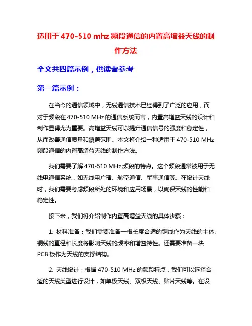
适用于470-510 mhz频段通信的内置高增益天线的制作方法全文共四篇示例,供读者参考第一篇示例:在当今的通信领域中,无线通信技术已经得到了广泛的应用,而对于频段在470-510 MHz的通信系统而言,内置高增益天线的设计和制作显得尤为重要。
高增益天线可以提升通信信号的强度和稳定性,从而改善通信质量和覆盖范围。
本文将介绍一种适用于470-510 MHz 频段通信的内置高增益天线的制作方法。
我们需要了解470-510 MHz频段的特点。
这个频段通常被用于无线电通信系统,如无线电广播、航空通信、军事通信等。
在设计天线时,我们需要考虑频段所处的环境和应用场景,以确保天线的性能和稳定性。
接下来,我们将介绍制作内置高增益天线的具体步骤:1. 材料准备:我们需要准备一根长度合适的铜线作为天线的主体。
铜线的直径和长度将影响天线的频率和增益特性。
还需要准备一块PCB板作为天线的支撑结构。
2. 天线设计:根据470-510 MHz的频段特点,我们可以选择合适的天线类型进行设计,如单极天线、双极天线、贴片天线等。
在设计天线的过程中,需要考虑天线的尺寸、形状和布局,以确保天线能够有效地辐射和接收信号。
3. 天线制作:根据设计方案,在PCB板上绘制天线的布局图和尺寸标注。
然后,将铜线焊接到PCB板上,形成天线的主体结构。
在焊接过程中,需要确保铜线与PCB板的连接牢固,以防止天线松动或断裂。
4. 天线调整:制作完成后,需要进行天线的调试和测试。
通过专业的测试仪器和设备,可以测量天线的频率响应、驻波比、增益等参数。
根据测试结果,可以对天线进行调整和优化,以提高其性能和稳定性。
5. 安装部署:将制作好的高增益天线安装在通信设备中,并放置在合适的位置。
在安装和部署过程中,需要注意避免天线与其他金属结构或干扰源的干扰,以确保通信信号的质量和稳定性。
制作适用于470-510 MHz频段通信的内置高增益天线是一项复杂而细致的工作,需要综合考虑天线设计、制作和调试等多个环节。
西安星恒通通信技术有限公司SCE-370A型3.7米天线安装、使用、维护手册西安星恒通通信技术有限公司SCE-370A型天线安装、维护、使用手册1.天线简介SCE–370A型3.7米卫星通信天线是西安星恒通通信有限公司研制生产的卫星通信地球站天线。
该天线是高性能的双修正环焦型天线,由于采用了计算机优化设计和先进的制造工艺,因而该天线具有高增益、低旁瓣、高极化鉴别率、小电压驻波比等良好特性。
该天线主反射面是赋形抛物面,由十二块瓜瓣样的铝合金面板组成,每块面板均采用高精度拉伸成型蒙皮与高刚度骨架铆接而成,这种复合结构的面板保证了天线重装精度,减少了安装工作量,使天线有很强的抗风能力和足够的强度。
天线副反射面及馈源系统均由数控车床加工成型,表面处理采用导电阳极化、热喷锌后烤漆(包括底漆和面漆)的处理工艺。
天线全部钢结构部件采用热浸锌或热喷锌后喷漆的表面处理工艺,全部连接用标准件采用不锈钢件,增强了它的防腐蚀能力,使天线的使用寿命大于15年。
天线座架形式采用有限可控立柱式俯仰-方位型,保证天线系统具有0°~360°的方位转动和 0°~ 90°的俯仰转动范围。
由于天线口径较小,一般采用手动调节;若使用方有特殊要求,也可提供电动调节。
天线系统由天线和馈源两大部分组成。
由于天线波束较窄,手动型天线备有方位微调机构,确保准确对星。
天线部分由主反射面、副反射面、天线座架、辐射板等组成(见附图1:3.7m天线结构图)。
馈源部分由波纹喇叭、双工器两部分组成。
SCE-370B型天线安装、维护、使用手册2. 3.7米天线技术指标SCE-370A型天线安装、维护、使用手册3.天线系统的安装(结构图见附图1)天线安装分以下几个步骤:1.安装天线座座架的安装:从座架包装箱取出方位架(序号7)和底架(序号8),将底架下法兰盘与地基相连接(在连接之前,应清理地基表面及地脚螺栓上的锈灰并上机油),用6个M20的螺母、平垫圈、弹簧垫圈仔细拧紧。

《低剖面低净空5G移动终端天线》篇一一、引言随着5G通信技术的快速发展,移动终端设备正日益普及。
在5G时代,低剖面和低净空的天线设计成为移动终端设备的重要组成部分。
本文将深入探讨低剖面低净空5G移动终端天线的设计原理、性能特点以及在实际应用中的表现。
二、低剖面低净空5G移动终端天线的概念及意义低剖面低净空5G移动终端天线是指具有较小垂直尺寸和空间占用率的天线设计。
这种设计在满足5G通信需求的同时,有效降低了设备的整体尺寸和空间占用,使得移动终端设备更加轻薄、便携。
在5G时代,低剖面和低净空的天线设计对于提升移动终端设备的用户体验、降低成本以及促进无线通信技术的发展具有重要意义。
三、低剖面低净空5G移动终端天线的设计原理1. 材质选择:选择具有高导电性能和较低密度的材料,如特殊合金和复合材料,以降低天线的重量和厚度。
2. 结构设计:采用先进的微带线、共面波导等平面结构,有效降低天线的剖面高度。
同时,优化天线内部的结构布局,减小空间占用。
3. 阻抗匹配与辐射优化:通过优化阻抗匹配和辐射效率,使天线在不同频段上表现出良好的性能。
此外,还可以通过增加匹配网络、优化接地结构等措施提高天线的稳定性。
四、性能特点1. 频带宽:低剖面低净空5G移动终端天线具有良好的频带性能,能够满足5G网络的各种频段需求。
2. 增益高:采用先进的设计理念和技术手段,提高了天线的辐射效率和增益,提高了通信质量。
3. 轻薄便携:由于采用了先进的设计材料和结构,使得天线的剖面高度和空间占用大大降低,移动终端设备更加轻薄、便携。
4. 良好的兼容性:该天线设计可与各种移动终端设备相兼容,满足不同设备的需求。
五、实际应用表现低剖面低净空5G移动终端天线在实际应用中表现出色。
首先,在智能手机领域,采用该设计的手机具有轻薄的外形和出色的通信性能,深受消费者喜爱。
其次,在物联网、无人机等移动设备中,该天线设计也发挥了重要作用,提高了设备的通信质量和稳定性。
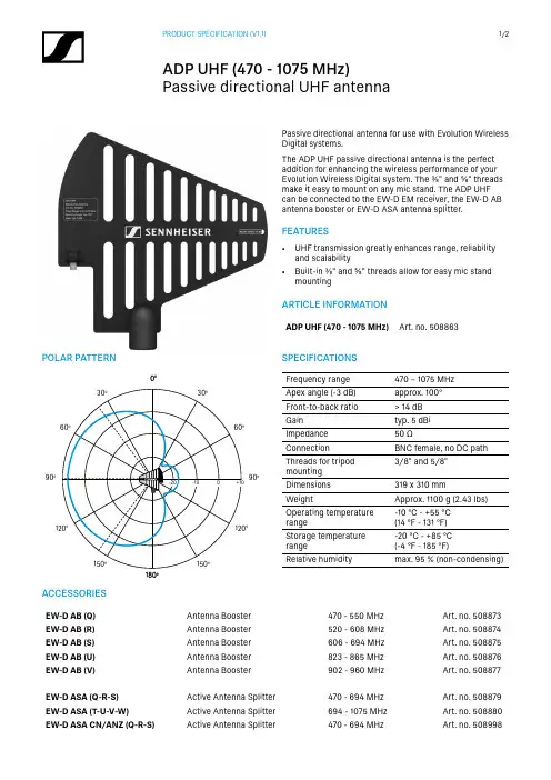
Passive directional antenna for use with Evolution Wireless Digital systems.The ADP UHF passive directional antenna is the perfect addition for enhancing the wireless performance of your Evolution Wireless Digital system. The ⅝" and ⅜" threads make it easy to mount on any mic stand. The ADP UHF can be connected to the EW-D EM receiver, the EW-D AB antenna booster or EW-D ASA antenna splitter.FEATURES• UHF transmission greatly enhances range, reliabilityand scalability • Built-in ⅝" and ⅜" threads allow for easy mic standmountingACCESSORIESEW-D AB (Q)Antenna Booster 470 - 550 MHz Art. no. 508873EW-D AB (R)Antenna Booster 520 - 608 MHz Art. no. 508874EW-D AB (S)Antenna Booster 606 - 694 MHz Art. no. 508875EW-D AB (U)Antenna Booster 823 - 865 MHz Art. no. 508876EW-D AB (V)Antenna Booster 902 - 960 MHz Art. no. 508877EW-D ASA (Q-R-S)Active Antenna Splitter 470 - 694 MHz Art. no. 508879EW-D ASA (T-U-V-W)Active Antenna Splitter 694 - 1075 MHz Art. no. 508880EW-D ASA CN/ANZ (Q-R-S)Active Antenna Splitter470 - 694 MHzArt. no. 508998ARTICLE INFORMATIONADP UHF (470 - 1075 MHz)Art. no. 508863SPECIFICATIONSFrequency range 470 – 1075 MHz Apex angle (-3 dB)approx. 100°Front-to-back ratio > 14 dB Gain typ. 5 dBi Impedance 50 ΩConnection BNC female, no DC path Threads for tripod mounting 3/8" and 5/8"Dimensions 319 x 310 mmWeightApprox. 1100 g (2.43 lbs)Operating temperature range-10 °C - +55 °C (14 °F - 131 °F)Storage temperature range-20 °C - +85 °C (-4 °F - 185 °F)Relative humiditymax. 95 % (non-condensing)POLAR PATTERN90°90°0°180°Sennheiser electronic GmbH & Co. KG · Am Labor 1 · 30900 Wedemark · Germany · DIMENSIONSPOSITIONING。
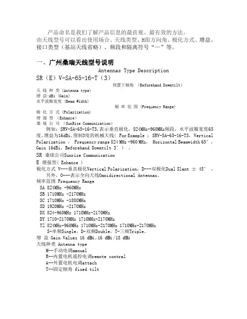
产品命名是我们了解产品信息的最直观、最有效的方法。
由天线型号可以看出使用场合、天线类型、H面方向角、极化方式、增益、接口类型(基站天线省略)、频段和隔离符号“—”等。
一、广州桑瑞天线型号说明Antennas Type DescriptionSR(E)V-SA-65-16-T(3)预置下倾角(Beforehand Dowmtilt)天线种类 (Antenna type)增益:dBi (Gain)水平波瓣宽度 (Beam Width)频率范围 (Frequency Range)极化方式 (Polarization)增强型(Enhance)桑瑞公司(SunRise Communication)例如:SRV-SA-65-16-T3,表示垂直极化,824MHz-960MHz频段,水平波瓣宽度65度,增益为16dBi,预制3度的机械天线( For Example : SRV-SA-65-16-T3, Vertical Polarization , Frequency range 824 MHz -960 MHz, Horizontal Beamwidth 65°,Gain 16dBi,Beforehand Dowmtilt 3°)。
SR 桑瑞公司Sunrise CommunicationE 增强型( Enhance )极化方式 V---垂直极化Vertical Polarization,D---双极化Dual Slant ± 45°,另外,O---表示全向天线Omnidirectional Antennas。
频率范围 Frequency RangeSA 824MHz -960MHzSB 1710MHz -2170MHzSC 1710MHz -1880MHzSD 1920MHz -2170MHzDX 824-960MHz 1710MHz-2170MHzDY 1710-2170MHz 1710MHz-2170MHzTZ 824MHz-960MHz 1710MHz-2170MHz 1710MHz-2170MHzS-单频Single,D-双频Double,T-三频Triple。
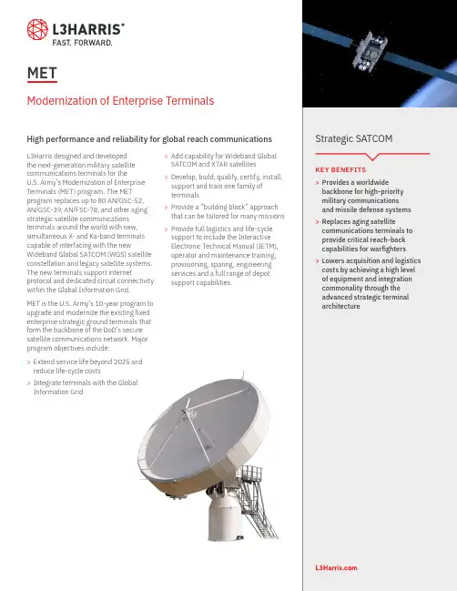
KEY BENEFITS>Provides a worldwidebackbone for high-priority military communications and missile defense systems >Replaces aging satellitecommunications terminals to provide critical reach-back capabilities for warfighters >Lowers acquisition and logistics costs by achieving a high level of equipment and integration commonality through the advanced strategic terminal architectureStrategic SATCOML3Harris designed and developed the next-generation military satellite communications terminals for theU.S. Army’s Modernization of Enterprise Terminals (MET) program. The MET program replaces up to 80 AN/GSC-52, AN/GSC-39, AN/FSC-78, and other aging strategic satellite communications terminals around the world with new, simultaneous X- and Ka-band terminals capable of interfacing with the newWideband Global SATCOM (WGS) satellite constellation and legacy satellite systems. The new terminals support internetprotocol and dedicated circuit connectivity within the Global Information Grid. MET is the U.S. Army’s 10-year program to upgrade and modernize the existing fixed enterprise strategic ground terminals that form the backbone of the DoD’s secure satellite communications network. Major program objectives include:>Extend service life beyond 2025 and reduce life-cycle costs >Integrate terminals with the Global Information Grid>Add capability for Wideband Global SATCOM and XTAR satellites >Develop, build, qualify, certify, install, support and train one family of terminals >Provide a “building block” approach that can be tailored for many missions >Provide full logistics and life-cycle support to include the Interactive Electronic Technical Manual (IETM), operator and maintenance training, provisioning, sparing, engineering services and a full range of depot support capabilities.METModernization of Enterprise TerminalsHigh performance and reliability for global reach communicationsNon-Export-Controlled Information.L3Harris Technologies is an agile global aerospace and defense technology innovator, delivering end-to-end solutions that meet customers’ mission-critical needs. The company provides advanced defense and commercial technologies across air, land, sea, space and cyber domains.Use of U.S. DoD visual information does not imply or constitute DoD endorsement.MET© 2020 L3Harris Technologies, Inc. | 06/2020 | BCS |20-DSD-222 | Rev-201CHARACTERISTIC/ TERMINALLARGE FIXED/LARGE FIXED HEMP TERMINALSMALL FIXED TERMINALSTANDARDTRANSPORTABLE TERMINALHARDENEDTRANSPORTABLE TERMINALFrequencies:X-band Rx: 7.25–7.75 GHz Tx: 7.9–8.4 GHz Rx: 7.25–7.75 GHz Tx: 7.9–8.4 GHz Rx: 7.25–7.75 GHz Tx: 7.9–8.4 GHz Rx: 7.25–7.75 GHz Tx: 7.9–8.4 GHz Ka-band Rx: 20.2–21.2 GHz Tx: 30.0–31.0 GHz Rx: 20.2–21.2 GHz Tx: 30.0–31.0 GHz Rx: 20.2–21.2 GHz Tx: 30.0–31.0 GHz Rx: 20.2–21.2 GHz Tx: 30.0–31.0 GHz G/T:X-band > 35 dB/K > 25 dB/K > 30 dB/K > 30 dB/K Ka-band > 38 dB/K > 30 dB/K > 34 dB/K > 34 dB/K EIRP:X-band > 117.5 dBm > 101 dBm > 112.5 dBm > 112.5 dBm Ka-band > 115.5 dBm> 101 dBm> 111.5 dBm> 111.5 dBmRF Compliance Per MIL-STD-188-164A (CN2)Per MIL-STD-188-164A (CN2)Per MIL-STD-188-164A (CN2)Per MIL-STD-188-164A (CN2)WGS CertifiedApproved Approved Approved Approved Operating Environment:Temperature –40°C to +49°C –40°C to +49°C –40°C to +49°C –40°C to +49°C Humidity10% to 90% w/condensation below 37.8°C 10% to 90% w/condensation below 37.8°C 10% to 90% w/condensation below 37.8°C 10% to 90% w/condensation below 37.8°C Wind 45 mph w/gusts to 65 mph (operational); 150 mph stowed 45 mph w/gusts to 65 mph (operational); 125 mph stowed 45 mph w/gusts to 65 mph (operational); 125 mph stowed Ops Van and Radome 150 mphIce/Snow 2 inches clear ice, snow load up to 40 lbs/ft2 2 inches clear ice, snow load up to 40 lbs/ft2 2 inches clear ice, snow load up to 40 lbs/ft2 2 inches clear ice, snow load up to 40 lbs/ft2EMI/EMC Per MIL-STD-461F Per MIL-STD-461F Per MIL-STD-461F Per MIL-STD-461F MTBF1,250 hours1,250 hours1,250 hours1,250 hoursHEMP ProtectionPer MIL-STD-188-125-1 (1) MIL-STD-188-125-2 (1) (HEMP Terminal only)Per MIL-STD-188-125-1 (1) and MIL-STD-188-125-2 (1)MET is comprised of five terminal configurations. The 12.2-meter Large Fixed Terminal offers simultaneous X-/Ka-bandcommunications with WGS satellites and Defenses Satellite Communications System (DSCS) backward compatibility. The hardened 12.2-meter Large Fixed Terminal also incorporates protection against high-altitude electromagnetic pulse (HEMP)threats. The 7.2-meter X/Ka dual-band Standard Transportable Terminal utilizes many of the Large Fixed Terminal features in a transportable system. The fourth variant is a HEMP X/Ka dual–band 7.2 meter Hardened Transportable Terminal. The (4.8-meter) X/Ka dual-band Small Fixed Terminal meets lower throughput requirements and can be mounted on small pads.FEATURES1025 W. NASA Boulevard Melbourne, FL 32919。