74253 TTL 三态输出双4选1数据选择器 复工器
- 格式:pdf
- 大小:56.95 KB
- 文档页数:6
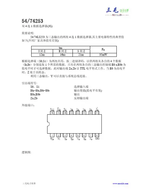
© 2000 Fairchild Semiconductor Corporation DS006416August 1986Revised March 2000DM74LS253 3-STATE Data Selector/MultiplexerDM74LS2533-STATE Data Selector/MultiplexerGeneral DescriptionEach of these Schottky-clamped data selectors/multiplex-ers contains inverters and drivers to supply fully comple-mentary, on-chip, binary decoding data selection to the AND-OR gates. Separate output control inputs are pro-vided for each of the two four-line sections.The 3-STATE outputs can interface directly with data lines of bus-organized systems. With all but one of the common outputs disabled (at a high impedance state), the low impedance of the single enabled output will drive the bus line to a HIGH or LOW logic level.Featuress 3-STATE version of DM74LS153 with same pinout s Schottky-diode-clamped transistors s Permit multiplexing from N-lines to one line s Performs parallel-to-serial conversion s Strobe/output controls High fanout totem-pole outputs s Typical propagation delayData to output 12 ns Select to output21 nss Typical power dissipation 35 mWOrdering Code:Devices also available in T ape and Reel. Specify by appending the suffix letter “X” to the ordering code.Connection Diagram Function TableAddress Inputs A and B are common to both sections.H = HIGH Level L = LOW Level X = Don't CareZ = High Impedance (OFF)Order Number Package NumberPackage DescriptionDM74LS253M M16A 16-Lead Small Outline Integrated Circuit (SOIC), JEDEC MS-012, 0.150 Narrow DM74LS253NN16E16-Lead Plastic Dual-In-Line Package (PDIP), JEDEC MS-001, 0.300 WideSelect Data InputsOutput OutputInputs Control B A C0C1C2C3G Y X X X X X X H Z L L L X X X L L L L H X X X L H L H X L X X L L L H X H X X L H H L X X L X L L H L X X H X L H H H X X X L L L HHXXXHLH 2D M 74L S 253Logic DiagramDM74LS253Absolute Maximum Ratings (Note 1)Note 1: The “Absolute Maximum Ratings” are those values beyond which the safety of the device cannot be guaranteed. The device should not be operated at these limits. The parametric values defined in the “Electrical Characteristics” table are not guaranteed at the absolute maximum ratings.The “Recommended Operating Conditions” table will define the conditions for actual device operation.Recommended Operating ConditionsElectrical Characteristicsover recommended operating free air temperature range (unless otherwise noted)Note 2: All typicals are at V CC = 5V, T A = 25°C.Note 3: Not more than one output should be shorted at a time, and the duration should not exceed one second.Note 4: I CC1 is measured with all outputs OPEN, and all the inputs grounded.Note 5: I CC2 is measured with the outputs OPEN, OUTPUT CONTROL at 4.5V and all other inputs grounded.Supply Voltage 7V Input Voltage7VOperating Free Air Temperature Range 0°C to +70°C Storage Temperature Range−65°C to +150°CSymbol ParameterMin Nom Max Units V CC Supply Voltage4.7555.25V V IH HIGH Level Input Voltage 2V V IL LOW Level Input Voltage 0.8V I OH HIGH Level Output Current −2.6mA I OL LOW Level Output Current 24mA T AFree Air Operating Temperature70°CSymbol ParameterConditionsMinTyp Max Units (Note 2)V I Input Clamp Voltage V CC = Min, I I = −18 mA −1.5V V OH HIGH Level V CC = Min, I OH = Max 2.43.1VOutput Voltage V IL = Max, V IH = Min V OLLOW Level V CC = Min, I OL = Max0.5Output VoltageV IL = Max, V IH = Min VI OL = 12 mA, V CC = Min 0.4I I Input Current @ Max Input Voltage V CC = Max, V I = 7V 0.1mA I IH HIGH Level Input Current V CC = Max, V I = 2.7V 20µA I IL LOW Level Input Current V CC = Max, V I = 0.4V −0.4mA I OZH Off-State Output Current with V CC = Max, V O = 2.7V 20µA HIGH Level Output Voltage Applied V IH = Min, V IL = Max I OZL Off-State Output Current with V CC = Max, V O = 0.4−20µA LOW Level Output Voltage Applied V IH = Min, V IL = Max I OS Short Circuit Output Current V CC = Max (Note 3)−20−100mA I CC1Supply Current V CC = Max (Note 4)712mA I CC2Supply CurrentV CC = Max (Note 5)8.514mA 4D M 74L S 253Switching Characteristicsat V CC = 5V and T A = 25°CNote 6: C L = 5 pF.From (Input)R L = 667ΩSymbol ParameterTo (Output)C L = 45 pF C L = 150 pF UnitsMinMax MinMax t PLH Propagation Delay Time Data to Y 2535ns LOW-to-HIGH Level Output t PHL Propagation Delay Time Data to Y 2030ns HIGH-to-LOW Level Output t PLH Propagation Delay Time Select to Y 4554ns LOW-to-HIGH Level Output t PHL Propagation Delay Time Select to Y 3244ns HIGH-to-LOW Level Output t PZH Output Enable Time to Output 1832ns HIGH Level Output Control to Y t PZL Output Enable Time to Output 2335ns LOW Level Output Control to Y t PHZ Output Disable Time from Output 41ns HIGH Level Output (Note 6)Control to Y t PLZOutput Disable Time from Output 27ns LOW Level Output (Note 6)Control to YDM74LS253Physical Dimensions inches (millimeters) unless otherwise noted16-Lead Small Outline Integrated Circuit (SOIC), JEDEC MS-012, 0.150 NarrowPackage Number M16A6D M 74L S 253 3-S T A TE D a t a S e l e c t o r /M u l t i p l e x e rPhysical Dimensions inches (millimeters) unless otherwise noted (Continued)16-Lead Plastic Dual-In-Line Package (PDIP), JEDEC MS-001, 0.300 WidePackage Number N16EFairchild does not assume any responsibility for use of any circuitry described, no circuit patent licenses are implied and Fairchild reserves the right at any time without notice to change said circuitry and specifications.LIFE SUPPORT POLICYFAIRCHILD’S PRODUCTS ARE NOT AUTHORIZED FOR USE AS CRITICAL COMPONENTS IN LIFE SUPPORT DEVICES OR SYSTEMS WITHOUT THE EXPRESS WRITTEN APPROVAL OF THE PRESIDENT OF FAIRCHILD SEMICONDUCTOR CORPORATION. As used herein:1.Life support devices or systems are devices or systems which, (a) are intended for surgical implant into the body, or (b) support or sustain life, and (c) whose failure to perform when properly used in accordance with instructions for use provided in the labeling, can be rea-sonably expected to result in a significant injury to the user. 2. A critical component in any component of a life support device or system whose failure to perform can be rea-sonably expected to cause the failure of the life support device or system, or to affect its safety or effectiveness.。