国际会议poster 模板
- 格式:ppt
- 大小:220.50 KB
- 文档页数:2

ei会议poster模板-回复如何制作一个EI 会议的海报模板。
第一步:确定主题和目标要制作一个成功的EI 会议海报模板,首先需要明确会议的主题和目标。
在中括号内的内容是“EI会议”,所以我们可以推断出这是一个关于情商(Emotional Intelligence)的会议。
其目标可能是促进人们对情商的认识和理解,并探讨如何在个人和职业生活中应用情商技巧。
在文章的剩余部分中,我们将着重介绍这些方面。
第二步:设计海报布局设计一个吸引人的海报布局是制作EI 会议海报模板的重要步骤。
以下是一些关键元素,可以帮助你创建一个专业和吸引人的设计:1. 选择合适的背景:可以使用鲜明的颜色和吸引人的图像作为背景,以吸引参会者的注意。
同时,背景应该与情商的主题相符。
2. 添加主题和日期:确保主题和日期清晰可见,并使用大型字体突出显示。
你可以选择一种现代而简洁的字体风格。
3. 插入相关图像和图表:使用与情商相关的图像和图表来帮助展示会议的内容和目标。
例如,可以使用表达情商的情绪图表或人际关系图像。
4. 添加必要的详细信息:在海报上包括会议地点、时间、演讲嘉宾和注册流程等相关信息。
确保这些信息清晰可见,并使用简洁的语言描述。
第三步:排版和字体选择正确的排版和字体选择能够提高海报的可读性和可理解性。
以下是一些建议:1. 使用明确的标题:使用大号字体和粗体显示大标题,突出显示会议的主题。
2. 使用分段和标题:将内容分为多个段落,并为每个段落添加标题。
这样,读者可以更轻松地浏览和理解信息。
3. 使用简洁明了的语言:避免使用过于复杂的句子和术语。
使用简洁明了的语言传达会议的内容和目标。
4. 选择合适的字体:选择易于阅读的字体,例如Arial或Helvetica。
确保字体大小合适,以便参会者在远处也能够轻松阅读。
第四步:添加配色方案选择正确的配色方案对于一个吸引人的海报模板至关重要。
以下是一些建议:1. 使用情绪和温暖的颜色:情商与情绪和人际关系有关,因此可以选择使用温暖和鲜明的颜色来体现这一主题。

IEEE会议poster模板回答标题:XXX会议poster报告一、引言本次poster报告主要介绍XXX会议的相关信息,包括会议的主题、目的、时间、地点等。
我们将通过展示一些与会议主题相关的图片和数据,向观众展示我们的研究成果。
二、研究背景和目的首先,我们将介绍研究的背景,包括行业现状、存在的问题以及相关研究现状。
然后,我们将明确本次研究的目的是为了解决什么问题或者达到什么目标。
我们的研究目标是针对XXX 领域的技术难题提出解决方案,并为行业的发展提供有价值的参考。
三、研究方法与结果接下来,我们将详细介绍我们采用的研究方法,包括数据收集、处理和分析的过程。
在介绍完方法后,我们将重点介绍我们通过研究发现的结果,包括我们得出的主要结论和相关数据。
我们将在poster上展示一些关键的图表和图像,以便观众更好地理解我们的研究成果。
四、结论与展望最后,我们将总结我们的研究成果,强调其价值和意义,并展望未来可能的发展方向。
我们将讨论如何将研究成果应用于实际生产中,以及可能面临的挑战和解决方案。
此外,我们还将讨论未来研究的潜在机会和研究方向。
五、致谢在poster的结尾,我们将对所有参与本次研究的成员表示感谢,并感谢所有观众的关注和支持。
我们希望我们的研究成果能够为行业的发展做出贡献,并期待与更多同行进行交流和合作。
六、附录附录部分将包含更多关于本次研究的详细信息,如数据来源、算法流程图等,供感兴趣的观众参考。
总结:本次poster报告旨在向观众展示我们的研究成果,并希望能够引起更多同行的关注和讨论。
我们相信,通过不断努力和创新,我们的研究成果将为行业的发展带来积极的影响。

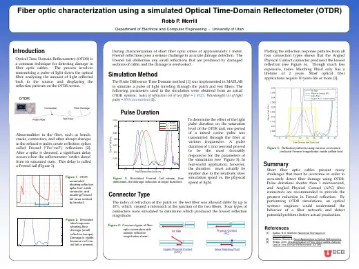
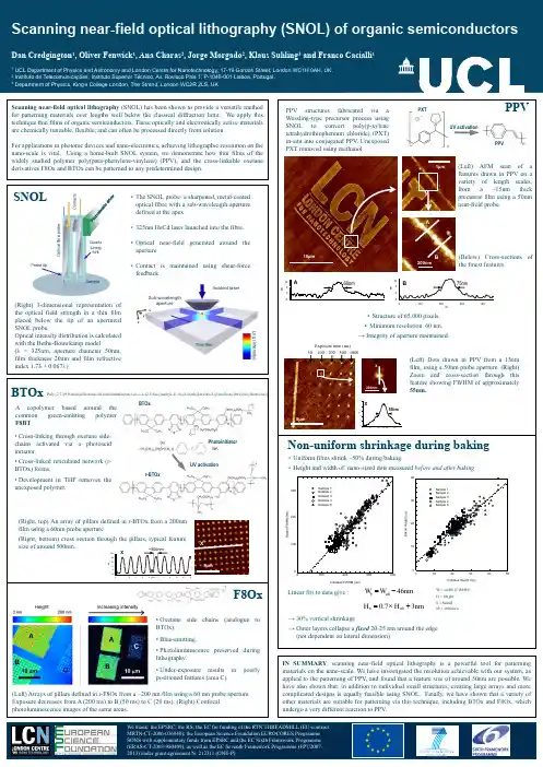
原创国际学术会议海报(poster)模板(英文)原创国际学术会议海报(poster)模板(英文)Fiber optic characterization using a simulated Optical TimeDomain Reflectometer (OTDR)Robb P. MerrillDepartment of Electrical and Computer Engineering - University of Utah IntroductionOptical Time Domain Reflectometry (OTDR) is a common technique for detecting damage in fiber optic cables. The process involves transmitting a pulse of light down the optical fiber, analyzing the amount of light reflected back to the source, and displaying the reflection patterns on the OTDR screen.During characterization of short fiber optic cables of approximately 1 meter, Fresnel reflections pose a serious challenge to accurate damage detection. The Fresnel tail obliterates any small reflections that are produced by damaged sections of cable, and the damage is overlooked.Simulation MethodThe Finite Difference Time Domain method [1] was implemented in MATLAB to simulate a pulse of light traveling through the patch and test fibers. The following parameters used in the simulation were obtained from an actual OTDR system: Index of refraction (n) of test fiber = 1.4525, Wavelength (λ) of light pulse = 850 nanometers [3] .Plotting the reflection response patterns from all four connection types shows that the Angled Physical Contact connector produced the lowest reflection (see Figure 6). Though much less expensive, Index Matching Fluid only has a lifetime of 2 years. Most optical fiber applications require 10 years life or more [3].Pulse DurationT o determine the effect of the light pulse duration on the saturation level of the OTDR unit, one period ofa raised cosine pulse was transmitted through the fiber at various frequencies. A pulse duration of 1 microsecond proved to be the most favorably responsive for the parameters of the simulation (see Figure 3). In realworld application, however, the duration must actually be smaller due to the relatively slow simulation speed vs. the physical speed of light.OTDR Saturation at Increased Pulse Durations 0.035 1 second 0.03 2 seconds 3 secondsAbnormalities in the fiber, such as bends, cracks, connectors, and other abrupt changes in the refractive index create reflection spikes called Fresnel ( Fre'-nel ) reflections [2]. After a spike is detected, a significant delay occurs when the reflectometer ‘settles down’ from its saturated state. This delay is called a Fresnel tail (Figure 1).Figure 1: OTDR screenshot showing reflection spike from cable connector, and resulting Fresnel tail (area marked by bracket)0.025Electric Field (V/m)0.020.01510.01Figure 5: Reflection patterns using various connectors (reduced Fresnel magnitudes inside yellow box)0.0050 1 1.5 2 2.5 3 3.5 4 Travel Distance from Source (m) 4.5 5SummaryShort fiber optic cables present many challenges that must be overcome in order to accurately detect fiber damage using OTDR. Pulse durations shorter than 1 microsecond, and Angled Physical Contact (APC) fiber connectors are recommended to provide the greatestreduction in Fresnel reflection. By performing OTDRsimulations, an optical systems engineer could understand the behavior of a fiber network and detect potential problems before actual production.Figure 3: Simulated Fresnel Tail skews, then obliterates, the damage reflection at larger durationsConnector TypeThe index of refraction of the patch vs. the test fiber was allowed differ by up to 10%, which created a mismatch at the junction of the two fibers. Four types of connectors were simulated to determine which produced the lowest reflection magnitude.15x 10-3Ideal Reflection Characteristics (No OTDR Saturation)105Figure 2: Simulated ideal response showing fiber damage (small reflection bumps). Damage is visible because no Fres-nel tail is present.Electric Field (V/m)Figure 4: Common types of fiber optic connectors with relative reflection magnitudes shownReferences[1] Sadiku, N.O. Matthew. Numerical Techniques in Electromagnetics [2] Newton, Steven A. Novel Approaches to Optical Reflectometry [3] Knapp, John. Characterization of FiberOptic Cables Using an Optical Time Domain Reflectometer (OTDR)0 2 2.5 3 Travel Distance from Source (m) 3.5Fiber optic characterization using a simulated Optical TimeDomain Reflectometer (OTDR)Robb P. MerrillDepartment ofElectrical and Computer Engineering - University of UtahIntroductionOptical Time Domain Reflectometry (OTDR) is a common technique for detecting damage in fiber optic cables. The process involves transmitting a pulse of light down the optical fiber, analyzing the amount of light reflected back to the source, and displaying the reflection patterns on the OTDR screen.During characterization of short fiber optic cables of approximately 1 meter, Fresnel reflections pose a serious challenge to accurate damage detection. The Fresnel tail obliterates any small reflections that are produced by damaged sections of cable, and the damage is overlooked.Simulation MethodThe Finite Difference Time Domain method [1] was implemented in MATLAB to simulate a pulse of light traveling through the patch and test fibers. The following parameters used in the simulation were obtained from an actual OTDR system: Index of refraction (n) of test fiber = 1.4525, Wavelength (λ) of light pulse = 850 nanometers [3] .Plotting the reflection response patterns from all four connection types shows that the Angled Physical Contact connector produced the lowest reflection (see Figure 6). Though much less expensive, Index Matching Fluid only has a lifetime of 2 years. Most optical fiber applications require 10 years life or more [3].Pulse DurationTo determine the effect of the light pulse duration on the saturation level of the OTDR unit, one period of a raised cosine pulse was transmitted through the fiber at various frequencies. A pulse duration of 1 microsecond proved to be the most favorably responsive for the parameters of the simulation (see Figure 3). In realworld application, however, the duration must actually be smaller due to the relatively slow simulation speed vs. the physical speed of light.OTDR Saturation at Increased Pulse Durations 0.035 1 second 0.03 2 seconds 3secondsAbnormalities in the fiber, such as bends, cracks, connectors, and other abrupt changes in the refractive index create reflection spikes called Fresnel ( Fre'-nel ) reflections [2]. After a spike is detected, a significant delay occurs when the reflectometer ‘settles down’ from its saturated state. This delay is called a Fresnel tail (Figure 1).Figure 1: OTDR screenshot showing reflection spike from cable connector, and resulting Fresnel tail (area marked by bracket)0.025Electric Field (V/m)0.020.01510.01Figure 5: Reflection patterns using various connectors (reduced Fresnel magnitudes inside yellow box)0.0050 1 1.5 2 2.5 3 3.5 4 Travel Distance from Source (m) 4.5 5SummaryShort fiber optic cables present many challenges that must be overcome in order to accurately detect fiber damage using OTDR. Pulse durations shorter than 1 microsecond, and Angled Physical Contact (APC) fiber connectors are recommended to provide the greatest。