学术会议poster模板
- 格式:ppt
- 大小:190.50 KB
- 文档页数:1


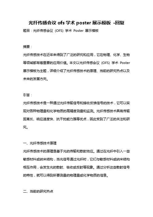
原创国际学术会议海报(poster)模板(英文)原创国际学术会议海报(poster)模板(英文)Fiber optic characterization using a simulated Optical TimeDomain Reflectometer (OTDR)Robb P. MerrillDepartment of Electrical and Computer Engineering - University of Utah IntroductionOptical Time Domain Reflectometry (OTDR) is a common technique for detecting damage in fiber optic cables. The process involves transmitting a pulse of light down the optical fiber, analyzing the amount of light reflected back to the source, and displaying the reflection patterns on the OTDR screen.During characterization of short fiber optic cables of approximately 1 meter, Fresnel reflections pose a serious challenge to accurate damage detection. The Fresnel tail obliterates any small reflections that are produced by damaged sections of cable, and the damage is overlooked.Simulation MethodThe Finite Difference Time Domain method [1] was implemented in MATLAB to simulate a pulse of light traveling through the patch and test fibers. The following parameters used in the simulation were obtained from an actual OTDR system: Index of refraction (n) of test fiber = 1.4525, Wavelength (λ) of light pulse = 850 nanometers [3] .Plotting the reflection response patterns from all four connection types shows that the Angled Physical Contact connector produced the lowest reflection (see Figure 6). Though much less expensive, Index Matching Fluid only has a lifetime of 2 years. Most optical fiber applications require 10 years life or more [3].Pulse DurationT o determine the effect of the light pulse duration on the saturation level of the OTDR unit, one period ofa raised cosine pulse was transmitted through the fiber at various frequencies. A pulse duration of 1 microsecond proved to be the most favorably responsive for the parameters of the simulation (see Figure 3). In realworld application, however, the duration must actually be smaller due to the relatively slow simulation speed vs. the physical speed of light.OTDR Saturation at Increased Pulse Durations 0.035 1 second 0.03 2 seconds 3 secondsAbnormalities in the fiber, such as bends, cracks, connectors, and other abrupt changes in the refractive index create reflection spikes called Fresnel ( Fre'-nel ) reflections [2]. After a spike is detected, a significant delay occurs when the reflectometer ‘settles down’ from its saturated state. This delay is called a Fresnel tail (Figure 1).Figure 1: OTDR screenshot showing reflection spike from cable connector, and resulting Fresnel tail (area marked by bracket)0.025Electric Field (V/m)0.020.01510.01Figure 5: Reflection patterns using various connectors (reduced Fresnel magnitudes inside yellow box)0.0050 1 1.5 2 2.5 3 3.5 4 Travel Distance from Source (m) 4.5 5SummaryShort fiber optic cables present many challenges that must be overcome in order to accurately detect fiber damage using OTDR. Pulse durations shorter than 1 microsecond, and Angled Physical Contact (APC) fiber connectors are recommended to provide the greatestreduction in Fresnel reflection. By performing OTDRsimulations, an optical systems engineer could understand the behavior of a fiber network and detect potential problems before actual production.Figure 3: Simulated Fresnel Tail skews, then obliterates, the damage reflection at larger durationsConnector TypeThe index of refraction of the patch vs. the test fiber was allowed differ by up to 10%, which created a mismatch at the junction of the two fibers. Four types of connectors were simulated to determine which produced the lowest reflection magnitude.15x 10-3Ideal Reflection Characteristics (No OTDR Saturation)105Figure 2: Simulated ideal response showing fiber damage (small reflection bumps). Damage is visible because no Fres-nel tail is present.Electric Field (V/m)Figure 4: Common types of fiber optic connectors with relative reflection magnitudes shownReferences[1] Sadiku, N.O. Matthew. Numerical Techniques in Electromagnetics [2] Newton, Steven A. Novel Approaches to Optical Reflectometry [3] Knapp, John. Characterization of FiberOptic Cables Using an Optical Time Domain Reflectometer (OTDR)0 2 2.5 3 Travel Distance from Source (m) 3.5Fiber optic characterization using a simulated Optical TimeDomain Reflectometer (OTDR)Robb P. MerrillDepartment ofElectrical and Computer Engineering - University of UtahIntroductionOptical Time Domain Reflectometry (OTDR) is a common technique for detecting damage in fiber optic cables. The process involves transmitting a pulse of light down the optical fiber, analyzing the amount of light reflected back to the source, and displaying the reflection patterns on the OTDR screen.During characterization of short fiber optic cables of approximately 1 meter, Fresnel reflections pose a serious challenge to accurate damage detection. The Fresnel tail obliterates any small reflections that are produced by damaged sections of cable, and the damage is overlooked.Simulation MethodThe Finite Difference Time Domain method [1] was implemented in MATLAB to simulate a pulse of light traveling through the patch and test fibers. The following parameters used in the simulation were obtained from an actual OTDR system: Index of refraction (n) of test fiber = 1.4525, Wavelength (λ) of light pulse = 850 nanometers [3] .Plotting the reflection response patterns from all four connection types shows that the Angled Physical Contact connector produced the lowest reflection (see Figure 6). Though much less expensive, Index Matching Fluid only has a lifetime of 2 years. Most optical fiber applications require 10 years life or more [3].Pulse DurationTo determine the effect of the light pulse duration on the saturation level of the OTDR unit, one period of a raised cosine pulse was transmitted through the fiber at various frequencies. A pulse duration of 1 microsecond proved to be the most favorably responsive for the parameters of the simulation (see Figure 3). In realworld application, however, the duration must actually be smaller due to the relatively slow simulation speed vs. the physical speed of light.OTDR Saturation at Increased Pulse Durations 0.035 1 second 0.03 2 seconds 3secondsAbnormalities in the fiber, such as bends, cracks, connectors, and other abrupt changes in the refractive index create reflection spikes called Fresnel ( Fre'-nel ) reflections [2]. After a spike is detected, a significant delay occurs when the reflectometer ‘settles down’ from its saturated state. This delay is called a Fresnel tail (Figure 1).Figure 1: OTDR screenshot showing reflection spike from cable connector, and resulting Fresnel tail (area marked by bracket)0.025Electric Field (V/m)0.020.01510.01Figure 5: Reflection patterns using various connectors (reduced Fresnel magnitudes inside yellow box)0.0050 1 1.5 2 2.5 3 3.5 4 Travel Distance from Source (m) 4.5 5SummaryShort fiber optic cables present many challenges that must be overcome in order to accurately detect fiber damage using OTDR. Pulse durations shorter than 1 microsecond, and Angled Physical Contact (APC) fiber connectors are recommended to provide the greatest。


竭诚为您提供优质文档/双击可除poster,session,模板篇一:学术装腔poster篇学术会议的交流主要有两种形式:oral和poster,就是所谓的口头和张贴两种。
poster,可以译为“海报”或“展板”,扼要展示自己或团队的工作,以供学术交流。
-------------------------------------------------------分割线-------------------------------------------------------------------假装前言话说我有这么门儿课,“学术写作”。
留了个作业,找篇文献,做一个poster。
2-3人小组作业,这个周日deadline。
话说一开始我没有组,正打算单干呢,昨天课前正好撞见我的俄罗斯同学,她说我也没组呀,咱俩吧;她前一天刚报告了一篇文献,说咱就这个吧,我心想也不错,反正自己也没开始。
昨天晚上大概不到10点的时候,这位俄罗斯妹子发来了她的初稿(见图一),邮件里还说“我在这上面花了1个小时40分钟,公平起见吧,你是不是也得差不多花一样的时间捏?”我暗自思忖,行啊,无所谓。
打开初稿一看,出了一身汗,全tm的工作量啊……不过心想她文章看了至少2遍吧,得嘞,开干吧。
图一.poster初稿从10点大约折腾到凌晨1点找素材,确定模板,然后睡觉去了。
今天早晨8:30起的,起来就断断续续干这件事儿,但累计也得五六个小时了吧。
我在晚上7点时候基本完成了这个poster,妹子给我挑了一些毛病,然后后面说“忽略那些小问题,我非常喜欢这个poster哈!”(你丫敢不喜欢……)8点半左右基本定型了,明天早起再最后看一眼。
闲言少叙,正题吧。
-------------------------------------------------------分割线-------------------------------------------------------------------正文部分先是一些关于poster的基本要点和原则:制作软件-ppt!poster的制作软件是ppt,以前一直以为是什么高级软件,但现在发现ppt这货还真是挺强大的。

光纤传感会议ofs学术poster展示模板-回复题目:光纤传感会议(OFS) 学术Poster 展示模板摘要:光纤传感技术在近年来得到了广泛的研究和应用,它在物理、化学、生物等领域都有着重要的应用价值。
本文以光纤传感会议(OFS) 学术Poster 展示模板为主题,详细介绍了光纤传感技术的原理、当前的研究热点以及未来的发展方向。
引言:光纤传感技术是一种通过光纤传输信号和接收反馈信号的技术,它可以实现对各种物理量和化学物质的高精度测量和监测。
光纤传感技术具有传输距离长、响应速度快、抗干扰能力强等优点,因此受到了广泛的关注和研究。
一、光纤传感技术原理光纤传感技术的原理是基于光的传输和散射效应。
通过在光纤中引入一些敏感材料或纳米结构,当光信号通过光纤时,它们与敏感材料或纳米结构相互作用,会发生光的散射、吸收或反射等现象。
通过分析这些散射信号的特性,就可以得到所要测量的物理量或化学物质的信息。
二、当前的研究热点1. 光纤传感技术在生物医学领域的应用光纤传感技术在生物医学领域有着广泛的应用,可以实现对生物组织的显微镜观察、生化分析等。
目前,研究人员正在探索基于光纤传感技术的生物传感器、生物成像等方面的应用。
2. 光纤传感技术在环境监测领域的应用光纤传感技术在环境监测领域也有着重要的应用,可以实现对环境污染物、大气污染物等的快速监测。
研究人员正在研究基于光纤传感技术的水质检测、空气质量监测等方面的应用。
3. 光纤传感技术在工业制造领域的应用光纤传感技术在工业制造领域也有着广泛的应用,可以实现对材料表面缺陷、温度、压力等参数的监测。
研究人员正在研究基于光纤传感技术的无损检测、工业自动化监控等方面的应用。
三、未来的发展方向1. 多模光纤传感技术的研究目前光纤传感技术主要采用单模光纤进行传感,为了提高传感信号的灵敏度和精度,研究人员正在研究多模光纤传感技术。
多模光纤传感技术可以实现对更多物理量和化学物质的测量,有着广阔的应用前景。