高压注浆泵维修保养说明书
- 格式:doc
- 大小:49.50 KB
- 文档页数:2
WM and WMR SeriesHigh Pressure Pump ServiceRainman Technology Pty Ltd#17 / 10-18 Orchard RoadBrookvale, NSW 2100Australia************************+61 433 826 626Version 1.1Table of ContentsPump Description 1Routine Pump Maintenance 2Oil Change 2 Preventing Cavitation 2Replacing the Valves 3Overview 3 Procedure 4 Replacing the Packings 6 Overview 6 Procedure 7 Setting Relief Valve 12 Troubleshooting 14 Maintenance Log 15Pump DescriptionThe high pressure pump is the heart of your Rainman watermaker. It creates the high pressure required for the reverse osmosis membranes to extract the fresh water from seawater. We use the best quality piston pump from General Pump, an American subsidiary of Interpump Group in Italy. Although it is a very simple and highly reliable pump, basic maintenance is required to maximise its performance and life span. Many customers may never need to read beyond the Routine Pump Maintenance section of this manual. However, the rest of this manual is included to assist those that may need to perform greater levels of maintenance on more heavily used systems.Depending on which Rainman watermaker model you own, there will be one of two different high pressure pumps in your system. If you have the older Mk1 electric (either AC or 12VDC) manufactured through January 2019, or any petrol (gasoline) model, your system will have a General Pump WM Series pump. If you own an electric (AC or 12VDC) Mk2 system, manufactured after February 2019, your system will have a General Pump WMR Series pump.The internals of both pumps are almost identical with only minor changes that are mostly in the manifold (stainless steel section of the pump). The photos and exploded diagrams in this document are for the WMR, but are almost the same for the WM pumps. All procedures described in this document apply equally to the WM and WMR pumps.General Pump WM Series (left) and WMR Series (right) high pressure pumpsExploded view of WMR series pump showing pistons and manifoldRoutine Pump MaintenanceVery little routine maintenance is required on your General Pump high pressure pump. Required maintenance is in your operations manual, but is also included here for completeness of this document. Oil ChangeWhen replacing the oil in the pump, use SAE-30 weight oil. General Pump generally recommends an oil change after the first 50 hours, then after each 300 hours of use thereafter. These pumps are designed for significantly higher operating pressure and flow rates, so the oil break down is slower than normal operation for this design. As such, it is not critical to maintain high discipline on this oil change schedule.The method to change oil in your pump is outlined in the watermaker operations manual. Preventing CavitationThe most important maintenance required to maximise the life of your pump is to prevent pump cavitation. Symptoms of cavitation include extra noise, high pressure hose vibration, and significant pressure fluctuation. Causes are anything that restricts flow to the pump. The watermaker operations manual covers more detail, but the two most frequent causes are not changing the prefilter or lift pump impeller frequently enough.Extended cavitation will prematurely wear the packings.Replacing the ValvesOverviewEach of the three cylinders in the pump has two spring loaded one way valves. One valve allows water to be pushed into the cylinder by the lift pump as the piston retracts. The second valve opens as the piston forces the water under high pressure through the manifold. O-rings are used to seal around the valves.Only one valve kit (RM01) is necessary to replace all the valves in the pump. The kit includes new O-rings and valve assemblies.Exploded view of WMR series manifold, showing valve configurationProcedureing a 22mm spanner or socket, remove the valve cap. Examine threads and O-ring. Replace O-ring(item 1) if there is any evidence of cuts, abrasions, distortion or wear.2.Remove valve assembly (item 2) from valve cavity.3.Remove valve seat O-ring (item 3) from valve cavity.4.Inspect manifold for wear or damage.5.Install new O-ring (item 3) in valve seat cavity.6.Insert valve assembly (item 2) into valve cap asshown.7.Coat the threads of the valve cap with anti-seizegrease (such as Renolit ST-80) and reinstall valve cap.Torque to 40 Nm (30 Ft-Lbs).Replacing the PackingsOverviewThe purpose of the packings is to allow the pump to push water through at high pressure while also preventing it from leaking out of the pump along the pistons. The hard high pressure seals contain the pressure within the manifold of the pump, but some moisture slides out with the piston on each stroke. The softer low pressure seals then prevent the water from leaking out of the pump. Normal symptoms of worn packings is water dripping from the weep holes underneath the pump.General Pump WMR packing kitIn the photo to the right are the following seals from top tobottom:•Low pressure seal (item 2 in diagram).This is the onewith stainless steel spring visible inside .•Stainless ring case (item 4 in diagram) with O-ring(item 3). Ensure O-ring is on the case, and is sitting inthe correct groove as per photo to the right (the onewithout holes). If O-rings in the kit came separatedfrom steel casing put them on before proceeding•Glyd high pressure seal, (item 5 in diagram).•Square high pressure seal, (item 6 in diagram).Procedure1.Remove head bolts using a 5mm Allen key and slide manifold away from the crankcase. Remove it asstraight as possible so as not to stress the plungers or rods inside the power end of the pump. It is normal for some packing assemblies to remain on the plungers. It may be necessary to rotate the crankshaft and/or use pry bars to separate manifold from crankcase.2.Remove the low pressure seals (item 2) using yourfingers. Take careful note of which way seals werefacing in order to correctly insert the new seal later.3.Remove the stainless steel case (item 3 / 4) where low pressure seals (item 2) were installed. Tightnessof stainless casings varies from pump to pump. It may be possible to remove the rings by inserting a finger and pulling outwards. If more force is necessary, use a 17-18mm diameter object (such as a blind bearing puller or screwdriver handle) and gently pull them out with a slight rocking motion. Since they are being replaced, damage to the old packings is inconsequential. Important:take care not to score or mark the manifold's machined surfaces.4.Remove high pressure seals (item 5 / 6) using yourfinger by gently pulling them upwards. If more forceis necessary, try using plastic or timber tools in orderto avoid damaging machined surfaces of cavity. Takecareful note of the seal’s orientation in order tocorrectly insert the new seals later.5.Thoroughly clean and inspect cavity for unusual wearor cracks.6.Press the glyd high pressure seal (item 5) into squarehigh pressure seal (item 6).7.Set the high pressure seal insertion guide (item 8) inmanifold cylinder. Do not grease any portion of thepacking assembly during this step.8.Gently place assembled glyd rings (items 5 / 6) insideinsertion guide (item 8) so they are resting evenly.9.Insert pusher tool (item 9), blunt end facing forwardand firmly press down to set glyd rings (items 5 / 6) in the manifold.10.Set low pressure seal guide (item 7) over seal casing(item 3 / 4) ensuring recess for seal is facing upwards.11.Gently place low pressure seal (item 2) into the guide (item 7) ensuring the open spring side of theseal is facing toward the casing and resting evenly.12.Insert pusher tool (item 9) into collar with narrow endfacing forward. Firmly press down to set seal in casing.13.Confirm that the O-ring is in the correct groove oncasing (item 3 / 4). At this point you should not beable to see the spring in the low pressure seal (item2) as it should be facing toward the casing itself.14.Check that spacer rings (item 1) are on each plungeras per photo. These rings are non-wearing so it is notrequired to replace them. Apply a very thin coating ofsilicone grease to each plunger.15.Slide the casings (items 3 / 4). on each plunger using low pressure seal guide (item 7). Ensure the blacklow pressure seal (item2) faces towards the power end of the pump, as per photo. Ensure they are straight to prevent damaging new seals.16.Reseat the manifold gently pushing it back into place.Install it straight with minimum wiggle.17.Once manifold is properly seated, install head boltsand begin torque sequence. Tighten to 12 Nm or 8.9Ft-lbs.Setting Relief ValveA relief valve is part of every Rainman watermaker as a safety precaution. It prevents build up of excessive pressure in the RO system if the control valve is accidentally closed too far. If the system does get over pressured, the relief valve opens and recirculates water through the pump to ensure no damage or high pressure leaks occur.In normal use the relief valve remains closed at all times. If the pressure reaches approximately 62 bar (900 psi) the valve starts to open, returning some water to the intake side of the system. At approximately 69 bar (1000 psi) it will be completely open, limiting the maximum output pressure of the PSU to approximately 69 bar (1000 psi). All relief valves are set in the Rainman factory during final testing of each system. In the highly unlikely event that a relief valve needs to be replaced, it will need to be set to the correct opening pressure. This section describes the procedure for setting the correct opening pressure, using the pressure gauge on any of the Rainman RO systems. It should be emphasised that it is highly unlikely you will ever need to replace or adjust the relief valve.All petrol/gasoline systems and original design, pre-January 2019, Mk1 electric systems utilise the VS100 relief valve, which is separate to the WM series pump itself. On Mk2 electric systems, manufactured after February 2019, the WMR pump has an integrated relief valve built into the manifold. You will need to remove the shell to access the relief valve on all cased electric systems. A separate document exists to remove the shell on Mk1 electric systems.Petrol/gasoline PSU WM Pump Mk1 Electric PSU WM Pump Mk2 Electric PSU WMR PumpNote that the VS100 relief valve is installed upside down on the Mk1 Electric PSU with the WM pump. Directions here are given as if you are looking at the end hexagonal adjustment cap.Once you have replaced the relief valve, and before replacing the plastic case of your PSU, reconnect the particle filter housing so that you can perform the following steps.1.Loosen the locking nut underneath the largehexagonal part of the relief valve.2.Place the pickup hose into a water source and connectthe RO unit as during normal operation.3.With the pressure control valve on the RO system fullyopen (counter-clockwise), run the PSU until only clearbubble free water comes out brine hose.4.Turn the pressure control valve clockwise until it isfully closed whilst watching the pressure on the gauge.New relief valves from the factory are typically pre-setto a low pressure, so you should be able to close thevalve fully before the pressure reaches 55 bar (800psi). If the pressure reaches 55 bar (800 psi) before thevalve is fully clockwise, then the relief valve is alreadyset too high. In this case, turn the hexagonal part ofthe relief valve anti-clockwise three times and go backto step 3.5.With the PSU running and the pressure control valvefully closed (clockwise), turn the adjustment cap onthe relief valve clockwise until the pressure gaugereaches 55 bar (800 psi).6.Fully open the pressure control valve on the RO unit(anticlockwise) and turn off the PSU.7.Turn the adjustment cap on the relief valve clockwiseone complete turn (360°).8.The relief valve is now set correctly to 69 bar (1000psi). Lock the adjustment cap using the locking nut orsome other thread locker e.g. Loctite or similar.TroubleshootingThe troubleshooting table is highly technical and specific only to the high pressure pump, not your Rainman watermaker in general. In the vast majority of operational troubleshooting issues, you should utilise the table in the general operations manual.Maintenance Log。
| April 2022Operation & Maintenance Manual | 04/2202-9245ME : ACHL Series Pump2FAILURE, IMPROPER SELECTION OR IMPROPER USE OF THE PRODUCTS AND/OR SYSTEMS DESCRIBED HEREINOR RELATED ITEMS CAN CAUSE DEATH, PERSONAL INJURY AND PROPERTY DAMAGE.This document and other information from Parker Hannifin Corporation, its subsidiaries and authorized distributors provide product and/or system options for further investigation by users having technical expertise. It is important that you analyze all aspects of your application and review the information concerning the product or system in the current product catalog.Due to the variety of operating conditions and applications for these products or systems, the user, through its own analysis and testing, is solely responsible for making the final selection of the products and systems and assuring that all performance, safety and warning requirements of the application are met.The products described herein, including without limitation, product features, specifications, designs, availability and pricing, are subject to change by Parker Hannifin Corporation and its subsidiaries at any time without notice.ALL PARKER VALVES MUST PASS A RIGID OPERATIONAL AND LEAKAGE TEST BEFORE LEAVING THE FACTORY. IT IS RECOMMENDED AFTER ANY REASSEMBLY, THE VALVE SHOULD BE TESTED BY THE USER FOR OPERATION AND LEAKAGE. IF THESE INSTRUCTIONS ARE NOT FULLY COMPLIED WITH, THE REPAIRED PRODUCT MAY FAIL AND CAUSE DAMAGE TO PROPERTY OR INJURY TO PERSONS. PARKER HANNIFIN CANNOT ASSUME RESPONSIBILITY FOR PERFORMANCE OF A CUSTOMER SERVICED VALVE.Live Chat Support is available from /IPD when the Chat icon “ ” is visible on screen.Parker Instrumentation Products Divison (IPD)02-9245ME : ACHL Series PumpOperation & Maintenance Manual | 04/223Product DrawingsTypical Pump Cross Sectional View ....................................................................................4 ACHL Pump Dimensional View . (5)Operation & Maintenance Information1.0 Introduction (6)2.0 Meaning of Safety Words .......................................................................................... 63.0Product Specification (6)4.0 Unpacking ..............................................................................................................6 5.0 Tools ...................................................................................................................... 6 6.0 Installation .............................................................................................................. 7 6.1 Compressed Air Supply . (7)6.2 Liquid Section ......................................................................................................... 87.0 Pump Start-Up ........................................................................................................ 88.0 Process Media ........................................................................................................ 99.0Pump Functionality (10)10.0 Suggested Maintenance (11)T roubleshooting Information11.0 Repair Kit Options .................................................................................................. 11 12.0 ACHL Series Drawings ............................................................................................12 13.0 Trouble Shooting-Pneumatic Section ...................................................................... 14 14.0 Trouble Shooting-High Pressure, Liquid Section .. (15)15.0 Service (15)T able of ContentsPageOperation & Maintenance Manual | 04/2202-9245ME : ACHL Series Pump4Typical Pump: Cross Sectional View(ASL Pump Shown)02-9245ME : ACHL Series PumpOperation & Maintenance Manual | 04/225ACHL Pump Dimensional ViewAll ACHL Series Pumps have a 1/4" FNPT regulated main air drive supply connectionNote:• Each Mounting Bracket includes (2) 11/32" (8.73) holes for 5/16" Bolts.• Spool air tubing not shown for clarity.• All dimensions are for reference only and are subject to change without notice.• Primary Dimensions: Inches• Secondary Dimensions: (Millimeters)Left View6Section 3.0 Product SpecificationsSection 1.0IntroductionThe Parker Autoclave Engineers pump discussed in this manual is operated using compressed air up to 150 psi (10 bar). Parker Autoclave Engineers ACL Series pumps are used for pumping oil, water and oil/water mixtures. Special seals are also available for chemical service. Please contact Parker Autoclave Engineers to discuss availability of special seals. The pump operates using a pressure ratio of the air piston surface area to the liquid plunger surface area.(Output liquid pressure = actual pump pressure ratio x input air pressure). Refer to the product literature for each pump model’s actual air pressure ratio.Section 2.0Meaning of Safety WordsA safety related message is identified by a safety alert symbol and a signal word to indicate the level of risk involved with a particular hazard. The definitions of the three signal words are as follows:Special notes intended to bring attention to procedures that must be followed to ensure proper installation and performance will be placed in a box labeled NOTICE.Section 4.0The pump has been assembled and pressure tested at Parker Autoclave Engineers and is ready to be put into service. The shipping carton should be opened and the contents carefully examined upon receipt from the carrier. Make sure there is no obvious damage to the contents. DO NOT use the equipment if any damage is evident.If damage has occurred, file a claim with the shipper be-fore contacting Parker Autoclave Engineers Service Department.Examine all material within the container and check against the packing list to be sure all items are accounted for and are not damaged. Verify that the equipment model number supplied agrees with what was ordered.See assembly drawing for product specifications:- Pump Geometry- Pump Materials of Construction- Maximum Allowable Working Pressure- Maximum Working Temperature- Pressure Ratio- Displacement- Repair Kit Part Numbers- Torque Information- WeightsUnpackingSection 4.0UnpackingAt minimum, the tools required for installation of the pump include a torque wrench, an open end wrench adapter (crows foot adapter) and an open end adjustable wrench. Refer to the Tools, Maintenance and Installation Manual provided with the Data Book for information on torque wrenches and torque values for Parker Autoclave Engineers tubing and fittings.Section 5.0ToolsOperation & Maintenance InformationOperation & Maintenance Manual | 04/22 02-9245ME: ACHL Series Pump02-9245ME : ACHL Series PumpOperation & Maintenance Manual | 04/227Section 6.0InstallationSection 6.1Compressed Air SupplyUnless otherwise noted, all air line accessories for the pump air drive should have, at minimum, a 1/4" FNPT connection. The tubing/piping used to connect the components should have the maximum ID the pressure rating will allow. Reducing the size before the air inlet will reduce air pressure flow andreduce flow rate of the pump.NOTICEThe main air drive connection port on the pump is a female 1/4" FNPT and is located in the spool valve housing.The use of an air line lubricator is not required and is not recommended. The oil in the air lubricator will cause the factory installed grease to be purged from the pump. Once an air lubricator is used the pump can never again be operated withoutan air lubricator.NOTICEAn air line filter with a minimum 5 microns filtration rating must be used on the supply line. If the air supply is not dry, a mist separator must be used to remove moisture in the air line.The pump is designed to function from 15 psi to 150 psi (1 to 10 bar) air input pressure.For best performance and life, the pump should be installed in the vertical position. This will prevent side loading on the air piston seals. The pump will, however, function in any position.The pump will attach to the mounting location using (4) 5/16" bolts. There are 4 holes provided on each pump for mounting.Operation & Maintenance Manual | 04/2202-9245ME : ACHL Series Pump 8Section 4.0UnpackingAll ACHL series pumps have a high pressure liquid outletport located on the side of the pump head. The suction inlet port on all ACHL series pumps is positioned either at the bottom or side of the head depending on the model purchased. See order code details in the product litera-ture for catalog number suffix.Inlet: A liquid filter with at least a 100 mesh size must be installed before the suction port inlet to prevent dam-age to the check valves and high pressure seals due to debris.Section 6.2Liquid Section For best performance, a liquid supply reservoir should be located higher than the inlet gland on the pump to create a small pressure head. Be sure to make an air tight seal between the reservoir and the pump inlet connection. The connections between the reservoir and pump inlet should not be reducedfrom the 3/8" FNPT connection size.NOTICEThe tubing or piping should be made from a corrosion resistant material and sized with a maximum ID to fit the 3/8" pipe connections.Restricting flow at the liquid inlet will causeproblems with check valve performance and reduceoutput flow.NOTICEOutlet: The outlet tubing ID must, at minimum, match the same size of the pump check valve gland port. Referto product literature for outlet connections details for each pump. Reducing outlet tubing or connection will reduce output liquid flow capacity.Section 4.0UnpackingSection 7.0Pump Start-Up Air Line SchematicAs shown above, a filtered main air supply line is required. The filtered air supply will go to a pressure regulator which can be set to achieve the desired output liquid pressure according to the pressure ratio of the pump.LIQUID INLETAIRREGULA TORAIR02-9245ME : ACHL Series PumpOperation & Maintenance Manual | 04/229The pumps unique design allows for self priming.To prime, regulate the air pressure to between 5-15 psi or use an air flow regulator to reduce to a slow stroke frequency. With the high pressure side connected to a vented system, allow the pump to cycle till a consistent flow of liquid is achieved.Let the pump flow freely to purge any air in the liquid system. Loosening the outlet gland or pipe can also assist in priming the pump.Section 4.0UnpackingSection 8.0Process Media Parker Autoclave Engineers pumps discussed in thismanual are used for pumping oil, water and oil/water mixtures. Special seals are also available for chemical service. Please contact Parker Autoclave Engineers todiscuss availability of special seals.Pumps are not designed to run for long periods of time without liquid process media. Short, dry pumping cycles should not be a cause for concern.However, pumps are built using lubricant in the seal areas and pumping without fluid will wear away lubricant and compromise the seal .The operating temperatures of the pump are between 0°F to 140°F (18°F to 60°F).Operation & Maintenance Manual | 04/2202-9245ME : ACHL Series Pump10Section 4.0UnpackingSection 9.0Pump Functionality When the pump is installed, regulated air is connectedto the spool housing at the ¼” FNPT pump inlet.The explanation below assumes pump is already primed with liquid.1. The pump is supplied with the piston in theupward position, which keeps the pilot valve in the open position.2. When regulated air is supplied to the pump, it enters the spool housing and energizes the large end of the spool, which shifts the spool to the left.3. The shifting of the spool causes regulated air to pass through the spool valve and pushes the air piston and liquid plunger d ownward toward the pump head.4. The liquid plunger moving toward the headcompresses fluid and forcing the inlet check valve to close and the outlet check valve to open.5. The plunger continues in the downward motion until it reaches the full stroke length.6. At the end of the stroke, air pressure is released from the large side of the spool, which causes the spool to shift and exhaust the air from the top of the piston through the muffler.7. The spring underneath the piston then returns the piston to the starting position.8. During the return, the pump performs a suction stroke. During a suction stroke, the plunger is moving away from the head causing the inlet check valve to open, which allows liquid to be drawn into the head while the outlet check valve is forced closed.9. Once the pump returns to the original starting position, the pilot valve opens and the entire process will continue to repeat until thepump reaches its stal pressure.Note: The ACHL series pump can be operated using a manual hand lever.Push the hand lever down to manually compress fluid and build liquid pressure. You can either stop when you reach your desired pressure, or when the pump reaches the end of its stroke. At the end of the stroke, keep your hand on the hand lever and slowly allow the springs to return the pump hand lever to its original position and perform a suction stroke.Do not let go of handle until the springs have returned the hand lever to its original position. Repeat this action until desired output pressure is reached.02-9245ME : ACHL Series PumpOperation & Maintenance Manual | 04/2211Section 4.0UnpackingSection 10.0Suggested MaintenanceA.Before each pump use, a quick inspection should be performed to insure there are no loose bolts, nuts, set screws or check valve glands. Tighten any loose bolts and fittings ac-cording to the torque values listed on the pump assembly drawing. A visual inspection should also be made before each use and at startup to make sure there is no evidence of fluid leaks from bottom end cap, weep holes or check valves. Refer to the troubleshooting guide for solutions to these fluid leaks.B.The maintenance schedule of the pumpdepends on the frequency of use, cleanliness of media, type of media, cycle rates, output pres-sures, cleanliness of air or any other conditions that may be damaging to seal integrity.Once a clear pattern develops of how long a pump is in service before pump performance declines, it is recommended to performmaintenance in advance of this time frame.At minimum, perform maintenance on the pump once a year as described below.Maintenance would include:• Re-lubrication or replacement of spool valve o-ring• Re-lubrication or replacement of air drive seals• Re-lubrication or replacement of pilot valve o-rings and gaskets• Replace check valve components • Replace high pressure hydraulic seals C.Maintenance instructions are supplied with appropriate rebuild kits. Kit part numbers are listed on the assembly drawing.Section 4.0Unpacking Section 11.0ACHL Series Repair Kit OptionsOperation & Maintenance Manual | 04/2202-9245ME : ACHL Series Pump12Section 12.0ACHL72-01-N Series Pump Drawing02-9245ME : ACHL Series PumpOperation & Maintenance Manual | 04/2213Section 4.0Unpacking Section 12.0ACHL189-01-N Series Pump DrawingOperation & Maintenance Manual | 04/2202-9245ME : ACHL Series Pump 14TroubleshootingSection 4.0UnpackingSection 13.0Troubleshooting - Pneumatic Section Problem: Pump will not operate with low air pressure.Cause:Excessive friction of o-rings on the spool valve has increased the pressure requiredto move spool.Solution: Replace and lubricate the o-rings on spoolProblem: Pump can only be actuated at high air pressure.Cause: a) Air is leaking through the plunger bore in the top end cap.b) Air is leaking through the o-rings between the top end cap and air cylinder.c) Bottom cap breather vent clogged.Solution: a) Replace and lubricate o-rings on upper plunger and in the bore located in the top cap. b) Replace and lubricate o-ring on lip of top end cap.c) Clean or replace breather vent.Problem: Pump will not run and air escaped through the exhaust muffler. Cause: a) Spool valve o-rings are leaking.b) Spool sleeve o-rings are leaking.Solution: a) Replace and lubricate spool valve o-rings.b) Replace and lubricate sleeve o-rings.Problem: Pump will not run and air escapes through the breather vent in the bottom end cap Cause: a) Outside o-ring on air piston is leaking. b) Seal between air piston and liquid plunger is leaking.Solution: a) Replace and lubricate air piston o-ring.b) Add Loctite 2760 thread locker with sealant on the plunger threads (one piece plunger designs)..Problem: Pump operates at a high frequency and short strokes.Cause: a) The top pilot valve is defectiveb) Air is leaking through the piston bore in thetop end cap.Solution: a) Replace and lubricate both tappet gaskets and o-ring. If necessary, also replace the tappet rod. b) Replace and lubricate o-ring on upper plunger and in the bore located in thetop cap.Problem: Pump functions slowly or doesn’t operate at all.Cause: a) Condensation from air supply is freezing the spool valve.b) Air muffler is clogged.Solution: a) Stop pump for a short period and replaceor add a mist separator in the air line.b) Clean or replace air muffler02-9245ME : ACHL Series PumpOperation & Maintenance Manual | 04/2215Section 4.0UnpackingSection 14.0Troubleshooting - High Pressure, Liquid Section Problem: Pump does not produce liquid flow, operates irregularly or does not maintain pressure.Cause: a) Air in the hydraulic system. b) Suction line excessively long. c) Suction tubing sized too small. d) Failure of one of the check valves. e) Liquid inlet filter is blocked.f) High pressure seal excessively worn.g) Supply liquid pressure head too low.Solution: a) Check inlet suction line and connections for leaks and allow pump to flow freely downstream so as to remove any air. b) Shorten liquid supply line.c) Increase tubing ID size between reservoir and pump inlet.d) Clean or replace both inlet and outlet check valve assemblies. e) Clean or replace liquid inlet filter. f) Replace high pressure seal assembly. g) Raise liquid reservoir to higher locationuntil pump is fully primed.Problem: Fluid escapes through the breather vent.Cause: High pressure seal is leaking.Solution: a) Clean fluid from air section. b) Replace and lubricate o-rings as necessary in the air section c) Replace high pressure liquid sealassembly.Section 4.0Unpacking Section 15.0ServiceParker Autoclave Engineers now require all pump repairbe sent to an authorized repair facility. Contact Parker Autoclave Engineers for recommendations.Pumps returned for service should be accompanied with the model number, serial number, manufacture date and problems you are experiencing.02-9245ME: ACHL Series Pump16Operation & Maintenance Manual | 04/22Operation & Maintenance Manual | 04/221702-9245ME: ACHL Series Pump02-9245ME: ACHL Series Pump18Operation & Maintenance Manual | 04/22Parker’s Motion & Control TechnologiesAt Parker, we’re guided by a relentless drive to help our customers become more productive and achieve higher levels of profitability by engineer-ing the best systems for their requirements. It means looking at customer applications from many angles to find new ways to create value. What-ever the motion and control technology need, Parker has the experience, breadth of product and global reach to consistently deliver. No companyknows more about motion and control technology than Parker. For further information call 1-800-C-Parker.02-9245ME April 2022© 2022 Parker Hannifin Corporation | Instrumentation Products Division1005 A Cleaner WayHuntsville, AL 35805 USA Tel: 256.881.2040Fax: /IPDOperation and Maintenance Manual ACHL Series: Liquid PumpsParker WorldwideNorth AmericaUSA – Corporate, Cleveland, OH Tel: +1 256 896 3000USA – IPD, Huntsville, AL Tel: +1 256 881 2040*****************USA – IPD, (Autoclave), Erie, PA Tel: +1 814 860 5700*******************CA – Canada, Grimsby, Ontario Tel +1 905-945-2274*********************South AmericaAR – Argentina, Buenos Aires Tel: +54 3327 44 4129 ******************BR – Brazil, Diadema, SP Diadema, SPTel: +55 11 4360 6700******************CL – Chile, Santiago Tel: +56 (0) 2 2303 9640******************MX – Mexico, Toluca Tel: +52 722 275 4200*******************Asia PacificAU – Australia, Dandenong Tel: +61 (0)2 9842 5150******************************CN – China, Shanghai Tel: +86 21 2899 5000*****************************HK – Hong Kong Tel: +852 2428 8008IN – India, MumbaiTel: +91 22 6513 7081-85ID – Indonesia, Tangerang Tel: +62 2977 7900********************JP – Japan, Tokyo Tel: +(81) 3 6365 4020******************KR – South Korea, Seoul Tel: +82 2 559 0400*******************MY – Malaysia, Selangor Tel: +603 784 90 800*******************SG – Singapore,Tel: +65 6887 6300*******************TH – Thailand, Bangkok Tel: +66 2 186 7000*********************TW – Taiwan, Taipei Tel: +886 2 2298 8987*************************VN – Vietnam, Hochi Minh City Tel: +848 382 508 56**********************Europe, Middle East, AfricaAE – UAE, Dubai Tel: +971 4 812 7100********************AT – Austria, Wiener Neustadt Tel: +43 (0)2622 23501-0*************************AT – Eastern Europe, Wiener Neustadt Tel: +43 (0)2622 23501 900****************************AZ – Azerbaijan, Baku Tel: +994 50 2233 458****************************BE/LU – Belgium, Nivelles Tel: +32 (0)67 280 900*************************BG – Bulgaria, Sofia Tel: +359 2 980 1344**************************BY – Belarus, Minsk Tel: +48 (0)22 573 24 00*************************CH – Switzerland, Etoy Tel: +41 (0) 21 821 87 00*****************************CZ – Czech Republic, Klecany Tel: +420 284 083 111*******************************DE – Germany, Kaarst Tel: +49 (0)2131 4016 0*************************DK – Denmark, Ballerup Tel: +45 43 56 04 00*************************ES – Spain, Madrid Tel: +34 902 33 00 01***********************FI – Finland, VantaaTel: +358 (0)20 753 2500*************************FR – France, Contamine s/Arve Tel: +33 (0)4 50 25 80 25************************GR – Greece, Athens Tel: +30 210 933 6450************************HU – Hungary, Budapest Tel: +36 223 885 470*************************IE – Ireland, DublinTel: +353 (0)1 466 6370*************************IT – Italy, Corsico (Ml)Tel: +39 02 45 19 21***********************KZ – Kazakhstan, Almaty Tel: +7 7273 561 000****************************NL – The Netherlands, Oldenzaal Tel: +31 (0)541 585 000********************NO – Norway, Stavanger Tel: +47 66 75 34 00************************PL – Poland, Warsaw Tel: +48 (0)22 573 24 00************************PT – Portugal, Leca da Palmeira Tel: +351 22 999 7360**************************RO – Romania, Bucharest Tel: +40 21 252 1382*************************RU – Russia, Moscow Tel: +7 495 645-2156************************SE – Sweden, Spånga Tel: +46 (0)8 59 79 50 00************************SK – Slovakia, Banská Bystrica Tel: +421 484 162 252**************************SL – Slovenia, Novo Mesto Tel: +386 7 337 6650**************************TR – Turkey, Istanbul Tel: +90 216 4997081************************UA – Ukraine, KievTel: +48 (0)22 573 24 00*************************UK – United Kingdom, Warwick Tel: +44 (0)1926 317 878********************ZA – South Africa, Kempton Park Tel: +27 (0)11 961 0700*****************************Questions?8325 Hessinger Drive Erie, PA 16509 USA Tel: 814 860 5700Fax: 814 860 Instrumentation Products Division。
GYZ 型高压油泵站使用和维护说明书 (沧州华峰工程专用)2007年8月北 京 电 力 设 备 总 厂 BEIJING POWER EQUIPMENT GROUP目录一.概述 (2)二.高压油系统元件说明 (2)三.高压油系统操作步骤 (5)1 .高压油系统的调试 (5)2 .高压油系统的运行 (6)3 .检修后的操作步骤 (6)4 .主要元件工作状态 (7)四.高压油系统的使用与维护 (7)1 .高压油系统的安装 (7)2 .油液的加注 (7)3 .高压油系统的循环 (7)4 .高压油系统的维护 (7)附图:液压原理图一、概述磨煤机加载系统是磨煤机的重要组成部分,由高压油泵站、油管路、液动换向阀、加载油缸、蓄能器等部件组成。
其功能如下:为磨辊施加合适的碾磨压力,加载压力由比例溢流阀根据指令信号来控制:同步升起和落下磨辊。
磨辊所需的碾磨压力是由液压系统提供的,加压系统包括三个油缸及蓄能器,蓄能器内有橡胶气囊,内充氮气,蓄能器的充油侧直接与油缸的活塞杆侧连接,三个油缸连接在公共供油管路上。
高压油泵站安装在靠近磨煤机的基础上,加载油缸和蓄能器安装在磨煤机上,三个带蓄能器的油缸由高压油泵站提供动力。
高压油泵站用管道连接到加载油缸上,连接管道采用0Cr18Ni9冷拔无缝钢管,管路连接用焊接式管接头。
油箱容积740L,第一次加油量约630L。
采用L-HM46抗磨液压油,油液从空气滤清器加入,并需经过过滤精度<10um的过滤机过滤。
在高压油系统设备和管路全部安装完后,高压油系统必须打油循环,当高压油系统油液清洁度达到NAS1638标准八级时,高压油系统方可投入运行。
高压油泵站见图16MG40.11.21,高压油系统液压原理见图21MG00.21,加载油缸见图30MG30.11.14。
二、高压站系统元件说明1、序号1和2,油泵组I油泵组I由电动机、齿轮泵、联轴器和支架等组成,油泵型号PFG-327/D-HT,电动机型号Y160L-8-HT,压力等级23MPa,功率7.5kW,转速720r/min,最大流量14.8L/min,油泵最大工作压力18MPa。
gyb-90e变频高压注浆泵说明书
1、打开混合器的注浆阀门,关闭混合器的放浆阀门,注水1分钟以上,湿润各注浆管路。
2、注浆过程中,浆液池内的液面应始终保持在完全掩埋吸浆滤网状态。
并不断搅动灰浆搅拌机的灰浆,保持水灰的混合状态,严禁灰浆沉淀堵塞,使吸浆回路工作在真空状态而损坏设备。
3、将吸浆滤网分别放入相应浆液池内,启动设备,开始注浆作业。
4、当每一个注浆孔注浆终结时或因故必须较长时间停泵时,都应立即把吸浆滤网放入清水池中,同时分别打开放浆阀、关闭注浆阀,洗泵两分钟以上,清除泵内的残存浆液,直至由放浆阀门排出的水为清水为止。
防止停机时间长而浆液凝固,造成不必要的麻烦。
5、当每班工作结束前,必须对注浆泵及输送管路进行彻底清洗,直至排出的水为清水为止。
双液压注浆泵的工作性能及效率同比挤压泵活塞泵有很大提高,同时双液压注浆泵即可单液注浆,可以实现水泥-水玻璃双液注浆。
GEHO TZPM型号高压煤浆泵的操作和维护摘要:简述GEHO TZPM500 与GEHO TZPM250型号高压煤浆泵的共同点和不同点,从操作和维护层面对高压煤浆泵进行着重介绍,典型问题的分析和判断。
关键词:活塞隔膜泵操作维护典型问题高压煤浆泵是水煤浆气化装置的关键设备,用来给气化炉提供一定压力和稳定流量的高浓度水煤浆。
国内应用较多的是荷兰的GEHO 隔膜活塞泵和德国的FELUWA 软管隔膜活塞泵。
在气化装置中(包括已建成投产的二期装置),共使用了四台GEHO隔膜活塞泵,其中TZPM250 型号三台, TZPM500 型号一台。
1 GEHO TZPM型号活塞隔膜泵简介GEHO活塞隔膜泵其TZPM型号是往复式定容排液泵,是为处理含有固体物质流体而设计的,特别适用于含有磨蚀性介质的场合,如煤浆、泥浆和矿泥。
泵送介质流量的改变通过变频电机的转速调节而实现。
泵送含固介质与处于推进液中的运动部件如活塞、缸套相隔离。
橡胶隔膜是隔离部件,中心嵌入有一个扁锥形钢板并在其推进液侧联结有一个带有磁铁的监测杆,正常操作时隔膜中心锥形板区域不与隔膜室前盖和后壁接触,通过位置开关来限制隔膜在正确的区间往复运动。
隔膜室介质侧底部联结吸入阀室和管道,顶部联结排出阀室和管道。
部件如活塞密封环、缸套、活塞杆可被视作无磨损部件。
唯一磨损的部件是吸入和排出阀阀盘,泵隔膜是可更换部件。
2 GEHO TZPM500 与GEHO TZPM250型号高压煤浆泵的比较一期气化装置(φ2.8m/φ2.8m,投煤浆量34.6 m3/h)选用了三台GEHO TZPM250型号高压水煤浆泵,二期气化装置(φ2.8m /φ3.2m,投煤浆量56m3/h)考虑选型的一致性和性能需求选用了一台GEHO TZPM500型号泵。
其性能参数比较如表一。
表一GEHO TZPM500与TZPM250泵均为三缸单作用,变频电机通过减速机驱动120°分布的曲轴带动活塞,改变旋转运动为往复运动,推动隔膜,通过隔膜室容积和压力的变化实现对介质的输送和增压。
注浆泵维护保养制度及流程英文回答:Maintenance and Maintenance System and Process for Grout Pump.Grout pumps are essential equipment used in construction and mining industries for injecting grout into structures. To ensure the proper functioning and longevity of the grout pump, it is crucial to have a well-defined maintenance and maintenance system in place. This system should include regular inspections, cleaning, lubrication, and replacement of worn-out parts.The maintenance and maintenance process for a grout pump typically involves the following steps:1. Regular Inspections: Regular inspections of the grout pump should be conducted to identify any signs of wear and tear, leaks, or malfunctioning parts. Thisincludes checking the motor, hoses, valves, and seals for any damage or leaks.2. Cleaning: The grout pump should be cleaned after each use to remove any grout residue or debris that may have accumulated inside. This can be done by flushing the pump with water or using a cleaning solution recommended by the manufacturer.3. Lubrication: Proper lubrication of the grout pump is essential to prevent friction and ensure smooth operation. The lubrication points should be identified, and the recommended lubricant should be applied regularly as per the manufacturer's instructions.4. Replacement of Worn-out Parts: Over time, certain parts of the grout pump may become worn-out and need replacement. These parts may include hoses, valves, seals, or motor components. It is important to keep a stock of spare parts and replace them as soon as signs of wear are noticed.5. Record Keeping: Maintaining a record of all maintenance activities, including inspections, cleaning,and part replacements, is important to track the history of the grout pump and identify any recurring issues. This record can also help in scheduling future maintenance tasks.中文回答:注浆泵维护保养制度及流程。
柱塞式高压注水泵(大港中成)保养规程一、保养等级的划分1、例行保养(每天)2、一级保养(720h)3、二级保养(4000h)二、保养周期、内容、标准(一)例行保养正常运行时每天要例行保养一次:1、检查压力是否正常,检查电流电压是否正常,并记录;2、检查注水泵是否有异响;3、检查填料及各密封部位是否有漏失现象,填料漏失要求在每分钟30滴之内;4、检查动力箱的看窗油位及油尺油位是否在1/2—2/3处,有无乳化变质现象;5、轴承箱温度和电机温度符合要求。
曲轴箱温不超70℃;电机温度不超80℃;6、检查各仪表是否完好、灵敏可靠;7、检查进、出口阀门、放空阀是否存在松、旷、漏的现象,及时整改;8、擦拭设备表面,保持设备清洁卫生;9、检查紧固各连接螺栓;10、检查清扫设备整体清洁。
(二)一级保养累计运转720小时,必须对设备进行一级保养,其作业内容如下:1、完成例行保养内容;2、紧固各部位螺栓;3、检查或添加电机轴承润滑脂、减速箱内润滑油;4、检查柱塞有无划痕,如有划痕必须及时更换;5、检查或更换填料;6、检查或更换阀座、阀片;7、检查柱塞连接卡子螺栓应紧固;8、检查皮带磨损情况,调整皮带的松紧及皮带轮的对中度;9、清洗曲轴箱呼吸阀;10、检查清洗过滤缸。
(三)二级保养累计运转4000小时,必须对设备进行二级保养,其作业内容如下:1、完成一级保养内容;2、检查或更换曲轴油封、拉杆油封;3、检查和清扫开关柜;4、两轮四点一线的检查与调整;5、检查进、排液阀座、阀片、阀体、弹簧及柱塞磨损情况,必要时检修或更换;6、清洗曲轴箱并更换润滑油;7、调整皮带的松紧及皮带轮的对中度;8、打开曲轴箱后盖,检查轴瓦紧固螺栓及防松垫片是否松动或损坏。
检查曲轴箱轴承是否完好,配合间隙最大不超过0.3-0.4mm,不符合则更换;9、检查电机接地及各项绕组的绝缘是否符合要求。
三、保养前的准备及保养步骤1、保养前准备工作1)检查柱塞式注水泵相关运行记录;2)准备保养工具和材料;3)检查柱塞式注水泵运行状况;4)通知采油队协调停泵,做好停运前准备;5)停泵。
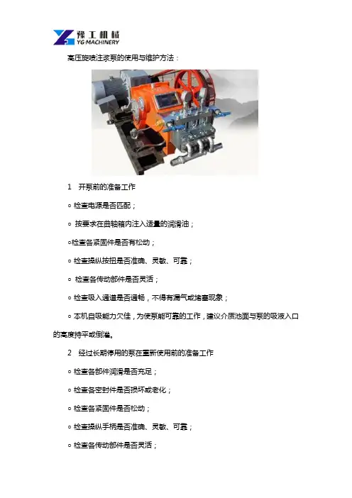
高压旋喷注浆泵的使用与维护方法:
1 开泵前的准备工作
○检查电源是否匹配;
○按要求在曲轴箱内注入适量的润滑油;
○检查各紧固件是否有松动;
○检查操纵按扭是否准确、灵敏、可靠;
○检查各传动部件是否灵活;
○检查吸入通道是否通畅,不得有漏气或堵塞现象;
○本机自吸能力欠佳,为使泵能可靠的工作,建议介质池面与泵的吸液入口的高度持平或倒灌。
2 经过长期停用的泵在重新使用前的准备工作
○检查各部件润滑是否充足;
○检查各密封件是否损坏或老化;
○检查各紧固件是否松动;
○检查操纵手柄是否准确、灵敏、可靠;
○检查各传动部件是否灵活;
○检查吸入通道是否通畅,不得有漏气或阻塞现象;
○曲轴箱内润滑油是否变质或油量过少。
3 泵的维修、保养
○经常检查各密封部件的情况,如有漏水。
漏油、漏气,应立即拆卸检修,更换损坏的密封件;
○定期检查各运动部件的情况,保证各润滑部件有充分的润滑油;
○经常检查各部位紧固件是否松动,螺栓的松动会造成机件的损坏并危及人身安全;
○注意关注运动部件是否伴有异常响动,如有卡阻应及时排除;
○注意检查安全阀的可靠性,确保超压时能可靠溢流;
○保证皮带的张紧状态。
河南豫工机械有限公司是河南专业机械制造商,专注于路面机械、环保机械、隧道边坡支护设备、预应力设备、高速公路、地铁涵洞、轻轨高铁、矿山资源开采、煤矿及非煤矿山领域的开发与销售,是个集研发,销售,线上线下为一体的
机械制造厂家。
感谢您的阅读!。
泵运行、操作、维护、保养制度为使各类泵安全、可靠运行,充分发挥设备效能,日常维护保养工作非常重要,根据所使用泵的特点,编写该使用维护保养制度,认真落实执行:1、保持设备清洁、干燥,无严重油污,无泄漏。
2、每班检查轴承箱内油位是否合适,正确的油位应在油位线位置附近,不得超过±2mm,需润滑脂要定期用黄油枪加油,并做详细记录。
3、经常巡查泵运行是否声音异常,振动及泄漏情况,发现问题及时汇报并且及时处理。
4、严禁泵在抽真空状态下运行,因泵在抽真空状态下运行不但振动剧烈,而且会影响泵的寿命,一定要特别注意!5、泵内严禁进入金属物体和超过泵允许通过的大块固体,严禁进入胶皮、棉丝、塑料布等柔性物质,以免破坏过流部件及堵塞叶轮流通,使泵不能正常工作。
因此,重点及时每班清理振动筛接液槽、清卤泵坑里的异物。
6、经常检查轴封水和密封水流量,压力是否合适,可采用检查轴封水管阀门开启度与检测填料箱温度的方法,温度高说明供水量不足,应及时给予调节.7、定期检测轴封水泄漏量,当泄漏量加大时,应调整填料压盖的螺栓,需要更换填料时要及时进行更换。
填料的填压方法:(1)填料长度按轴套圆周展开长度确定,各环填压时要将切口交错120°。
(2)填压好后一定要进行通水试运转,运转时再详细调整压盖螺栓,达到渗漏成点且不成线状为最佳,填料填压十分重要关系到密封状态好坏,而且还会影响泵的性能,应引起足够注意。
8、经常检测轴承温度,最高不得超过75℃。
9、泵连续运行800小时后应彻底更换润滑油一次。
10、经常检查进、出水管路系统支撑机构松动情况,确保支撑牢靠、稳固。
11、经常检查泵在基础上的紧固情况,联接应牢固、可靠及电机的地脚螺栓紧固和皮带松紧度。
12、开泵前应先开轴封水和冷却水,然后再开泵;停泵后,过15分钟后方可关闭轴封水及冷却水.1、开车前认真检查皮带连接卡子是否完好、牢靠,皮带上有无异物、障碍物,各传动机构位置是否正确,有无铁件,各螺栓是否牢固,尾部滚筒是否堵塞,有卡住之物,机械前后、左右是否有人,清扫器是否完好等,一切均正常确认无误,方可开启设备运行.2、在运行中应经常巡检电动滚筒、改向滚筒、托辊等各部位,有无异常响声,温度是否正常,皮带跑偏通过调型架及时调整,严防扯裂皮带撒盐、漏盐现象发生。
P0高压煤浆泵检修方案(大检修)清晨的阳光透过窗户,洒在办公室的角落,我泡了杯咖啡,准备开始今天的工作。
P0高压煤浆泵的大检修方案已经在我心中构思了许久,现在终于要付诸文字了。
一、检修前的准备工作1.我们要成立一个专门的检修小组,由经验丰富的工程师、技术人员和维修工人组成。
确保每个人都能明确自己的职责和任务。
2.要对检修所需的各种工具、备件和材料进行清点,确保数量充足,避免在检修过程中出现短缺现象。
3.在检修前,要对现场进行安全评估,确保在检修过程中不会对人员和设备造成伤害。
二、检修步骤及方法1.我们要对泵体进行检查,观察泵体是否有磨损、裂纹等现象。
如有问题,要及时更换泵体。
2.检查泵轴,看是否有弯曲、磨损等现象。
如有问题,要对泵轴进行校正或更换。
3.然后,我们要检查轴承,看是否有磨损、间隙过大等现象。
如有问题,要及时更换轴承。
4.在检查泵盖时,要观察密封垫是否老化、损坏,如有问题,要及时更换密封垫。
5.检查叶轮,看是否有磨损、裂纹等现象。
如有问题,要及时更换叶轮。
6.检查泵座,看是否有磨损、裂纹等现象。
如有问题,要及时更换泵座。
7.检查进出口阀门,看是否有损坏、泄漏等现象。
如有问题,要及时更换阀门。
8.在检修过程中,要对泵的各个部件进行清洗,确保没有油污、杂质等。
9.检修完成后,要对泵进行试运行,观察泵的运行情况是否正常。
三、检修后的验收工作1.检修完成后,要对泵的各项性能进行测试,确保泵的运行参数达到标准要求。
2.验收小组要对检修过程进行评估,确保检修质量符合要求。
四、检修中的注意事项1.在检修过程中,要注意安全,遵守操作规程,避免发生意外事故。
2.对泵的各个部件要轻拿轻放,避免损坏。
3.在更换部件时,要确保新部件的质量,避免因部件质量问题导致泵的运行不稳定。
4.检修过程中,要确保现场环境整洁,避免油污、杂质等对泵的运行产生影响。
5.检修完成后,要对泵进行试运行,确保泵的运行正常。
思绪如泉涌,我将这些内容一一记录在案。
高压注浆机常见维修方法高压注浆机是一种常用的建筑设备,它可以将混合物注入到建筑结构中,增强其强度和稳定性。
然而,使用过程中难免会出现故障,因此掌握常见的维修方法对保障设备的正常运行至关重要。
下面将介绍高压注浆机常见的维修方法。
一、泵体漏油如果出现泵体漏油的情况,需要检查油封是否磨损或破裂。
如果油封磨损或破裂,需要将其更换。
同时,还需要检查密封圈是否损坏或变形,如果是,也需要进行更换。
二、压力不稳定如果高压注浆机的压力不稳定,可能是由于泵体内的密封件出现了磨损或损坏,导致气体或液体泄漏。
此时需要检查泵体内的密封件,如果发现有磨损或损坏,需要进行更换。
三、泵体负荷过重如果高压注浆机的泵体负荷过重,可能是由于泵体内的过滤器被堵塞所致。
此时需要拆下过滤器清洗或更换。
四、泵体异响如果高压注浆机的泵体出现异响,可能是由于泵体内的轴承损坏所致。
此时需要将泵体拆卸下来,检查轴承是否已经损坏,如有损坏,则需要进行更换。
五、液压系统故障如果高压注浆机的液压系统出现故障,可能是由于油路堵塞或油泵内部有异物所致。
此时需要检查液压系统的油路,清除油路中的杂物和污垢,或者更换油泵。
六、电气系统故障如果高压注浆机的电气系统出现故障,可能是由于电源线路接触不良或电机损坏所致。
此时需要检查电源线路,确保接触良好。
如果电机损坏,则需要更换电机。
七、压力表不准确如果高压注浆机的压力表不准确,可能是由于压力表内部损坏或者被污垢堵塞所致。
此时需要将压力表拆下来进行检查,如果发现损坏或者被污垢堵塞,需要进行清洗或者更换。
对于高压注浆机常见的维修方法,需要根据具体情况进行具体分析和处理。
在维修过程中,需要注意安全,避免发生意外。
同时,定期进行保养和检查,可以有效预防故障的发生。
目录1 总则 (2)1.1 工艺流程概述 (3)1.2 设备的技术性能参数 (3)1.3 设备结构介绍 (4)2 设备完好标准 (5)2.1 零部件完整齐全 (5)2.2 设备运转正常 (5)2.3 技术资料齐全、准确 (6)2.4 设备环境整洁 (6)3 设备维护 (6)3.1日常维护 (6)3.2 定期维护 (7)3.3 故障处理 (8)3.4 紧急停车 (10)4 检修周期和检修内容 (11)4.1 检修周期 (11)4.2 检修内容 (11)5 检修方法及质量标准 (12)5.1 检修前的准备工作 (12)5.2 泵的检修 (12)6 试车与验收 (18)6.1 试车条件与准备工作 (19)6.2 油系统循环 (19)6.3 水压试验 (19)6.4 验收 (19)7 维护检修安全注意事项 (20)7.1 维护安全注意事项 (20)7.2 检修安全注意事项 (20)1 总则本规程适用于新能能源有限公司60万吨甲醇/年装置的P1303A\B\C高压煤浆泵的维护与检修,但不包括电气、仪表的维护检修。
1.1 工艺流程概述该泵从常压煤浆槽中吸入煤浆,升压至约8MPa,将煤浆送入气化炉。
共三台泵,每台泵与一台气化炉形成一个系列,自成系统,一旦发生故障需停泵检修,对应的气化炉即需停车。
1.2 设备的技术性能参数表1:泵的运行特性表2:GEHO数据表1.3 设备结构介绍高压煤浆泵由德国菲鲁瓦公司制造,适合于输送含有固体颗粒的液体,如淤泥、煤浆和泥浆等,也适合输送某些带腐蚀性或侵蚀性物质的液体。
泵的设计思想如下:被输送的液体并不接触活塞和缸体等部件,而是通过两个橡胶软管隔膜将被输送的液体与洁净的推进液体分隔开。
这样就大大降低了活塞密封环、缸体、活塞、连杆等部件的磨损,延长了泵的使用寿命。
1.3.1 驱动装置:该泵由变频电机驱动,主电机与减速箱安装在一个共用底盘上,电机与减速箱之间由弹性联轴器连接,减速箱与曲轴箱之间由空心轴连接,并带有防护罩。
CNC专用高压泵安装使用维护说明书上海冠派机电设备有限公司MPCBS-4L(图片仅供参考)目录1.1企业宗旨 (2)1.2价值观…………………………………………………………………………………….1.3目标……………………………………………………………………………………….1.4高压油泵作用……………………………………………………………………………..2.1注意事项2.1.1危险 (3)2.1.2注意 (4)2.2保修期限和范围………………………………………………………………………..2.3保修登记证书 (5)3.1系统主要参数 (6)4.1安装说明4.1系统定位 (7)4.2电源安装………………………………………………………………………………4.3电气接口4.3.1信号线连接 (8)4.3.2信号线连接图………………………………………………………………………. 4.4油管4.4.1进油管连接 (10)4.4.2回油管连接…………………………………………………………………………..4.4.3高压油管连接 (11)4.4.4排刀固定块安装……………………………………………………………………..4.4.5钻孔刀位固定块安装………………………………………………………………..4.4.6背面主轴固定块安装………………………………………………………………..4.4.7背面主轴中心出水油管安装………………………………………………………..5.1系统测试说明5.1.1测试步骤 (16)5.1.2压力设定………………………………………………………………………………5.1.3测试程序………………………………………………………………………………5.1.4程序举列……………………………………………………………………………….6.维护保养6.1滤芯清洗方法 (22)6.2滤芯更换………………………………………………………………………………..6.3定期维护………………………………………………………………………………..6.4中压泵更换………………………………………………………………………………6.5消耗部品表 (19)6.6系统主要部件 (20)7.故障排除7.1在本机上的报警 (21)7.2在机床上的报警………………………………………………………………………8.电气原理图 (22)9.出厂检验表 (27)1.1企业宗旨做CNC专用高压泵的领导者,通过提供卓越的服务,创新思路,创造性的解决方案,以改善加工效率和提高加工刀具的使用寿命。
堵漏注浆机保养说明书
防水堵漏高压注浆机启动前确认电钻正逆转开关是否在R(正转)位置。
电钻禁止以钻锤模式运转。
防水堵漏高压注浆机在操作使用环氧树脂时,请于环氧树脂限定操作时间内作业,可判断环氧树脂之温度,如环氧树脂之温度有提高之迹象,务必马上停止作业,迅速用专用清洗剂清洗本机,并确定清理干净。
施作完毕后务必马上以专用清洗剂清洗本机约2至3分钟,清洗完毕后留清洗剂于灌注机内部,防止药剂残留,导致塞机。
Standard Operating and Maintenance Instructionsfor Pumping SystemModel PS-150High Pressure Equipment Company, LLC2955 West 17th Street, Suite 6PO Box 8248Erie, PA 16505 USA814-838-2028 (phone)814-838-6075 (fax)Standard Operating and Maintenance Instructions for Pumping System Model PS-150:Description:The Model PS-150 Pumping System is designed for generating hydraulic pressure up to 150,000 psi by means of an air operated hydraulic pump and an intensifier. This system is complete and ready to operate requiring only the connection of an air supply of approximately 80 psi.Standard Features:The steel console is 26" wide, 24" deep, 40" high and includes manual valves, air regulator, filter and lubricator, air gauge, high pressure gauge, reservoir, oil filter, pump (0-16,000 psi), related high pressure tubing and fittings.The 0-20,000 psi pressure gauge is connected to the low pressure side of the intensifier which has a ratio of 10:1. Pressure on the high pressure side of the intensifier is thus determined by multiplying the gauge reading by 10. A small variation must be allowed for friction from the intensifier packing.The air operated hydraulic pump pressurizes the system to 16,000 psi with valves “A”and “B” closed and the intensifier piston is automatically positioned to the low pressure end of its stroke. With valves “A” and “C” closed, valve “B” is opened to allow the pump to pressurize the low pressure end of the intensifier. The fluid in the high pressure end of the intensifier is thus pressurized with a 10:1 ratio. If the intensifier reaches the end of its stroke before the desired pressure is achieved, the intensifier may be recycled. The intensifier output is approximately 1.2 cubic inches per stroke.The 150,000 psi Hydraulic Intensifier is designed with a ratio of areas on the two pistons of 10:1. Consequently, pressures up to 150,000 psi can be achieved by using a commercially available lower pressure (15,000 psi) pump.Material of construction for the pressure containing parts is 4340 alloy steel (or equivalent) properly heat treated for use at elevated pressures. Only non-corrosive type fluids should be used. The high pressure packing is housed in a separate removable stuffing box. This design permits improved concentricity and facilitates close tolerance machining of the packing area. Capacity per stroke at the high pressure end is 1.2 cubic inches. Capacity at the low pressure end is 12.6 cubic inches per stroke. Piston travel is 4 inches. Weight is approximately 150 pounds.Standard connections are for 1/4" O.D. tubing (HF4) on the low pressure end and 3/8" O.D. x 1/16" I.D. tubing (XF6) on the high pressure end.PS-150 ModelThe only connections required for installation of the system are an air supply and connection of the system to the pressure vessel or unit which is to be pressurized.The air supply line is connected directly to the side of the cabinet and is for ½ in NPT pipe. A larger air supply line is recommended if the system is quite a distance from the source of air. Pressure of the air supply should be approximately 60 psi minimum.The reservoir is built directly into the cabinet and should be filled with a suitable fluid before operation. The formulas as used by High Pressure Equipment Company are as follows for pressures up to 150,000 PSI:1 part kerosene2 parts hydraulic oilThe above mixtures may be purchased from High Pressure Equipment Company or other suitable fluids having a low viscosity may be used.Operating Instructions:The air regulator controls the output of the pump so that a given setting as shown on the small panel mounted air regulator gauge will operate the pump to a corresponding pressure. The pump will then automatically stop. Should there be any loss of pressure due to compaction of the tested material or temperature drop, the pump will automatically make up the pressure loss.1.Open Valve "C" and the "High pressure outlet valve". Close valve "B" and the "ventvalve".2.Rotate the regulator handle in a clockwise direction until the small air regulator gaugereads approximately 60 psi. Open the air inlet valve. The pump will now begin operating and will pump to approximately 16,000 psi (Should pressures of less than 16,000 psi bedesired, select a lower air inlet setting on the regulator.3.Close valve "C" and open valve "B-. The pump will now begin pumping into the bottomof the intensifier and compressing the fluid in the top of the intensifier to increase thepressure.NOTE, Model PS-150 is equipped with a 20,000 psi gauge and is connected to thelow pressure side of the intensifier. As the intensifier has a 10: 1 ratio. Thepressure on the high pressure side of the intensifier is 10 times that shown on thegauge. This of course, does not apply when valve UB" is closed and theintensifier is being by-passed or recycled.4.When the desired pressure is reached the air inlet valve should be closed or the airregulator handle rotated counter-clockwise thus reducing air input to the pump. If thedesired pressure is not reached, the intensifier must be recycled.The intensifier may be recycled by closing valve "B" and opening valve "C”. The pump is then operated to force the intensifier piston downward and force the oil in the bottom of the intensifier back into the reservoir. This may require upwards to 16,000 psi to return the piston. When the piston has returned to the bottom of the intensifier valve "C” should be closed and valve "E" opened. The pumping operation may then be continued as in steps 3 and 4 above.Venting the System:To vent pressure from the system simply open the "vent valve". This may be done at any time and will not damage the system if opened during operation for any reason.Use of the Air Regulator:The air regulator controls the pressure output of the pump and also the speed at which the pump operates. The operator may wish to control the system entirely by the regulator and leave the "Air Inlet Valve" open at all times. Thus the pump may be driven relatively fast until the unit approaches the desired pressure and then slowed down and finally stopped as it reaches this point. Do not exceed 60 psi on the regulator gauge.Position of the Intensifier Piston:The position of the piston may be determined listening to the pump. When the piston is at either end of its stroke the pump will stall out.Maintenance:The air line is equipped with a filter and lubricator. The air filter is provided to filter water from the air supply. Depending upon the amount of water in the air supply, the filter bowl will fill up over a period of time. This is easily drained by opening the small drain cock on the bottom of the bowl and allowing the water to drain into a container.The lubricator is provided in order to lubricate the air portion of the pump. This has been set at the factory for typical air flow conditions. An oil flow of approximately 3 to 5 drops per minute is recommended. This lubricator should be periodically checked and filled with a lubricating oil of approximately 150 to 200 s.s.u. @ 100 F (S.A.E. 10).The fluid within the reservoir should be kept clean in order to provide maximum life of the pump. When this fluid becomes excessively dirty, it is easily drained through the drain plug located at the bottom of the reservoir. A filter is provided between the reservoir and the pump.It is recommended that the disposable cartridge be removed and replaced should it become clogged with an excess of dirt. The valve between the reservoir and filter should be closed before removing the filter.Trouble Shooting:The pump is running but will not develop pressure:1. If the system has just been shipped, moved to a new location, or repairs have beenmade within the hydraulic lines, an "air lock" may have developed. A connection on the inlet side of the pump should be broken enough to determine whether or not the pump is receiving oil from the reservoir. If so, a connection on the outlet side of the pump should be broken slightly. With the pump operating (set the regulator so that the pump isoperating slowly) determine as to whether there is a flow through the lines. This willusually clear the "air lock" and the connection can be retightened.2. If the pump will not develop pressure and there does not appear to be an "air lock."The check valves on the inlet and outlet side of the pump should be cleaned or replaced. Spare parts or further information about your pumping system may be obtained direct from the HiP factory. Parts are generally stocked for immediate delivery.。
3SNS-A注浆泵使用说明书黑旋风工程机械开发(二o一二年二月版)欢迎您使用本产品。
在第一次使用本产品之前,请您务必仔细阅读随机配送的所有资料,这会有助于您更好地使用本产品。
如果您未按说明书的说明及要求操作本产品,或因错误理解等原因误操作本产品,本公司将不对由此而导致的任何损失承担责任。
请妥善保存该资料,以备用时急需。
本公司保留随时更改本产品的权利,恕不另行通知。
目次一、泵的概况 (1)二、工作原理 (2)三、泵各部分结构及机能 (2)1、机座总成 (2)2、NGW减速离合器总成 (3)3、变速器总成 (3)4、偏心轮传动总成 (3)5、泵头总成和排道管总成 (4)四、注浆泵的使用与维护 (5)1、开动前的使用与保养 (5)2、注浆泵在使用过程中的使用与维护 (5)3、停机时的注意事项 (5)五、泵的润滑 (6)六、泵的故障及排除 (6)七、3SNS-A注浆泵专用工具 (8)八、注浆泵易损零件 (8)九、隔膜耐振压力表 (8)十、附图(零部件图) (9)一、泵的概况1、泵的类型3SNS-A注浆泵属往复式单作用三柱塞泵。
2、泵的功用3SNS-A注浆泵是输送水泥浆或砂浆的注浆工程配套设备。
适用于坝基工程、固结注浆、隧道注浆及其他注浆工程。
也可代替泥浆泵用于地质岩心钻探工程。
3、泵的技术参数表一、泵的技术参数【注】1、随机不配高压胶管,用户根据实际需要长度自行配置。
2、本设备排浆接头尺寸为公制M39×2,用户选用GB 9065.3 A型扣压式接头DN25,配以O型圈φ23.6(径) ×2.65进行联接即可(安装方式见附图七)。
4、泵的特点:⑴.泵的流量是可调的,能满足注浆或钻探工艺的要求。
⑵.该泵每运转周期流量波动值小(流量不均匀系数S=1.04)。
其单位时间总排量基本上是恒定的,排出压力的变化对其影响较小。
⑶.用调节螺母来限压,操作方便,并起保护作用。
⑷.泵在工况运转时,无外部运动件,以利安全生产。
四、P1301高压煤浆泵一、结构说明:1.动力端:①机座是焊接件,焊后做消应处理,后盖和检修孔都有密封垫,以防润滑油溅出又防尘土侵入。
②动力由主动轴上的小人字齿轮传递到曲轴上大人字齿轮,该对人字齿轮均用合金钢制造,并经热处理有良好的耐磨性.③主动轴的轴承采用向心圆柱滚子轴承,在运行中主动轴在轴向上是浮动的,使主动轴上的小人字齿轮与曲轴上的大人字齿轮得到最佳的对中。
④曲轴是铸钢,经热处理,两端由双列向心球面滚子轴承支撑。
⑤连杆是合金钢铸件,经热处理,大头端、小头端均采用向心圆柱滚子轴承。
2.动力端润滑①曲轴上人字齿轮由油池内的油飞溅润滑。
②主动轴、曲轴的轴承和十字头均采用压力润滑。
润滑油管路中有过滤精度为100µm的出口滤油器。
3.液力端隔膜将液力端分割为推进液部分和料浆部分。
推进液部分由推进液接触的零件组成,包括隔膜室、缸套、活塞缸、活塞等。
料浆部分由与料浆接触的零件组成,包括进液管汇、进液阀、隔膜室盖、排液阀、排液阀汇、出口稳压器等。
3.1推进液部分活塞缸的活塞和缸套①活塞上有两组密封圈,一组用来密封推进液,另一组用来防止空气及冲洗液漏入,在两组密封圈之间有导向环,由它支承活塞和活塞杆的重量。
缸套内孔是淬硬的,所以即使有料浆渗入推进液也不致立即损坏缸套。
②活塞的冲洗为了保证活塞良好的工作条件,在活塞背部不断有润滑油冲洗,冲洗油由油泵供,油来自推进液油箱并返回推进液油箱。
③隔膜行程控制系统隔膜和探测杆装配在一起,探测杆上有磁性原件。
当推进液有过多或过少时,隔膜位置将超过它的正常界限,磁性原件到达引发前(或后)触发器的位置,触发器发出讯号,通过程控箱的作用,使电磁换向阀换向,卸去关闭二位二通阀(补油阀或排油阀)的空气压力,造成补油阀或排油阀打开一个预先设定的时间,达到补油或排油的目的。
补充推进液是在活塞的吸入行程时通过补油阀补入的,为了防止在活塞的排出行程时推进液被排出,在缸体和补油阀之间装有止逆阀。
高压注浆泵维修保养说明书
天津高压注浆泵维修,说明书,保养:
1.泵封存前或调换工作场地需长时间停泵时,必须用清水彻底冲洗泵头工作腔、截止阀、安全阀及吸液、排出管道内的残余介质,擦干并涂上机油,以免产生干固,锈蚀。
2.截止阀工作在介质为水时,可以作辅助调压。
介质中含有固体颗粒时严禁用末调节压力。
3.运转中,柱塞密封若有介质泄漏,说明前端则型密封损坏,必须及时更换.以免引起泄漏及加剧密封损坏。
注意压紧螺母不要调的太紧,以免导向密到抱死柱塞,使填科温升过高。
4.为了保证v型带的传动功率,应定期检查v型带的张紧程度。
安装时,一组皮带应使用具有同一长度公差的v型带,不得将不同长度的v带混合使用。
5.泵运行时一般处于高压状态,需注意安全。
必须配备具有相应知识的专人负责泵的操作、维护与保养,否则极易造成危害。
6.经常检查上、下阀座密封,如有损坏趋势,应立即更换。
否则将进一步引起阀座损坏。
7.安全阀的膜片必须按规定使用,严禁用其他零件代替,否则会造成液力端工作不正常,甚至造成人身、设备损坏。
8.介质必须使用推荐目数(20—22)或以上的过滤网过滤,否则会造成泵系统工作不正常,过粗的颗粒将降低冈座的使用寿命。
9.使用普通电机严荣带压启动,使用调速电机带压启动时,不可提速太快,以免运转超负荷。
10.每次使用停泵后,必须用清水特工作腔内介质清洗干净,以免介质干固,常工作。
11.泵的自吸能力欠佳,需将介质池面与泵的吸液端持乎或例灌。
12.调速电机出厂前均按照规定转速调整好,不得随意调整反馈量来提高转速,否则极易损坏电机及降低密封寿命。
13.最好按照推荐的牌号,使用符合标淮的润滑油,使用不合格的润滑油会降低曲轴的寿命,尤其是过于粘稠且不洁净的润滑油,会对曲轴,轴瓦等零件造成严重的损坏。
野外施工时,地盘不得倾斜放置,否则会影响泵的润滑,影响正常使用。
14.经常检查安全阀体中膜片与高压通道之间是否通畅,防止堵塞。
15.用于柱塞密封处的润滑泊不能断、缺、脏,否则会造成校塞及密封的损坏。
16.调速电机在出厂时速度已调校准确,如在位用中发生变化,在没有速度表酌情况下,可以按照以下方法调整:
a、在低速下目测柱塞冲次N(次份)
b、在冲次N×7.2727×1/u为当时电机的实际转速
c、如转速表的指示偏高,可调节反馈量调节电位器(在控制面板上),可使转速上升,反复调整,使指示值与计算值相符。
d、如转速表的指示偏低,则调节转速表校淮电位器,位之与计算值相符,或者可以按照c项说明调节。
17.作业过程中突然发生停电或其他意外情况,不能通过打清水清洗工作腔内残留介质时,必须人工清洗:
a.拆下排出管道,即可分别取下三个排出腔室;
b.拆下吸入通道,取下禁倔螺母及阀座压板即可进行清洗。
c.按照相反顺序安装。
18.关于调运电机的使用条件和注意事项,请参阅调速电机的使用说明书。
19.经常检查各处的螺栓,防止松动。
20.必须严格按照合格证或铭牌上的参数工作,以免发生意外。
高压旋喷桩施工图片、注浆机、高压柱塞泵、锚杆钻机、注浆泵、泵配件、机械零部件生产制作
天津市鑫腾达机械制造有限公司
/news/newsinfo-103.html。