RG178
- 格式:pdf
- 大小:26.07 KB
- 文档页数:1

RG2000-V8系列无线路由器使用说明书2018-07版本信息RG2000-V8 系列无线路由器使用说明书版本:RG2000-V8-V1.00-201807目录第一章约定说明 (1)1.1目的 (1)1.2适用范围 (1)1.3本书约定 (1)1.4专业术语 (2)第二章产品介绍 (4)2.1产品概述 (4)2.2功能特点 (4)2.3硬件规格 (5)2.4设备面板 (6)2.5安装说明 (8)2.6串口线缆 (11)第三章联机登录 (13)3.1环境要求 (13)3.2使用准备 (13)3.3配置计算机 (13)3.4通过Telnet登录系统 (16)3.5通过Console口登录系统 (16)3.6通过WEB登录系统 (17)第四章配置操作 (19)4.1设备状态 (19)4.1.1 设备基本状态 (19)4.1.2 WAN接口状态 (21)4.1.3 路由状态 (21)4.2网络配置 (22)4.2.1 接口管理 (22)4.2.2 端口管理 (27)4.2.3 VLAN管理 (27)4.2.4 WIFI配置 (28)4.2.5 DHCP配置 (30)4.2.6链路探测 (31)4.3路由配置 (32)4.3.1 静态路由 (32)4.3.2 策略路由配置 (33)4.3.3 OSPF配置 (34)4.3.4 IS-IS配置 (35)4.3.5 RIP配置 (37)4.4VPN配置 (37)4.4.1 GRE配置 (37)4.4.2 IPSec VPN (39)4.4.4 PPTP (43)4.5网络安全 (45)4.6.1 攻击防御 (45)4.6.2 访问策略配置 (45)4.6.3 PAT配置 (48)4.6.4 DMZ配置 (49)4.6.5 SNAT配置 (50)4.6.6 UPNP配置 (51)4.6.7 QOS配置 (52)4.6.8 IP-MAC绑定 (55)4.6.9 ALG配置 (55)4.6系统维护 (56)4.7.1 系统时间 (56)4.7.2 SNMP配置 (56)4.7.3 WEB管理 (57)4.7.4 TELNET设置 (58)4.7.5 软件升级 (60)4.7.6 配置管理 (61)4.7.7 设备重启 (61)4.7.8 日志管理 (62)4.7.9 通信检测 (63)4.7.10 激活参数 (64)第五章 CLI命令行介绍 (65)5.1CLI概述 (65)5.2CLI命令常识及使用技巧介绍 (66)5.2.1 命令帮助 (66)5.2.2 命令简写 (67)5.2.3 命令补全 (67)5.2.4 命令错误提示 (67)5.2.5 no命令 (68)5.2.6 历史命令 (68)5.3CLI命令详细介绍 (68)5.3.1 基础命令 (68)5.3.2 接口配置 (69)5.3.3 端口配置 (73)5.3.4 DHCP服务器配置 (74)5.3.5 VLAN配置 (75)5.3.6 DLDP配置 (75)5.3.7 BFD配置 (76)5.3.8 路由配置 (76)5.3.9 RIP路由配置 (77)5.3.10 OSPF路由配置 (78)5.3.11 ISIS路由配置 (78)5.3.13 访问策略配置 (80)5.3.14 静态ARP配置 (81)5.3.15 PAT配置 (81)5.3.16 DMZ配置 (82)5.3.17 ALG配置 (82)5.3.18 UPNP配置 (83)5.3.19 IPSEC配置 (83)5.3.20 GRE配置 (84)5.3.21 L2TP配置 (85)5.3.22 PPTP配置 (89)5.3.23 MPLS配置 (90)5.3.24 QOS参数配置 (93)5.3.25 GPON参数配置 (96)5.3.26 SNMP参数配置 (96)5.3.27 NTP配置 (97)5.3.28 WEB配置 (97)5.3.29 系统信息 (98)5.3.30 日志信息 (98)5.3.31 软件升级 (99)5.3.32 设备参数 (99)5.3.33 端口镜像命令 (99)5.3.34 测试工具命令 (99)5.3.35 主机名及密码修改 (100)5.3.36 系统时间 (100)5.3.37 重启设备 (100)第一章约定说明1.1目的本说明书用于指导RG2000-V8系列4G路由器的安装调试、使用及维护。
RG-S2928G-S安全智能千兆交换机产品V1.2目录1产品概述 (1)2产品特性 (2)3技术参数 (4)4典型应用 (6)5订购信息 (7)1 产品概述RG-S2928G-S交换机产品,是锐捷网络基于网络安全和易用好管理的理念推出的新一代安全智能交换机,充分融合了网络发展需要的高性能、高安全、多业务、易用性特点,为用户提供全新的技术特性和解决方案。
RG-S2928G-S不但提供诸如防ARP欺骗、防网络攻击、防非法DHCP、防网络环路等各项安全功能,同时更提供简单易用的WEB管理界面,在保有复杂安全技术的同时,提供简单易用的用户体验。
RG-S2928G-S采用绿色节能的无风扇设计,不但提供全静音的用户体验,更是完全消除了风扇带来设备故障,极大提高了设备的稳定性和使用寿命。
2 产品特性全面的安全控制策略●硬件实现端口与MAC地址和用户IP地址的灵活绑定,严格限定端口上的用户接入;●通过将端口设为保护端口即可简单方便地隔离用户之间信息互通,保障了信息安全,同时不必占用VLAN资源;●专用的硬件防范ARP网关和ARP主机欺骗功能,有效遏制了网络中日益泛滥的ARP网关欺骗和ARP主机欺骗的现象,保障了用户的正常上网;●支持DHCP snooping,可只允许信任端口的DHCP响应,防止未经管理员许可私自架设DHCP Server,扰乱IP地址的分配和管理,影响用户的正常上网;并在DHCP监听的基础上,通过动态监测ARP和检查源IP,可有效防范DHCP动态分配IP环境下的ARP主机欺骗和源IP地址的欺骗;●基于源IP地址控制的Telnet和Web设备访问控制,增强了设备网管的安全性,避免黑客恶意攻击和控制设备;●SSH(Secure Shell)和SNMPv3可以通过在Telnet和SNMP进程中加密管理信息,保证管理设备信息的安全性,防止黑客攻击和控制设备,保护网络免遭干扰和窃听;●通过内在的多种安全机制可有效防止和控制病毒传播和网络流量攻击,控制非法用户使用网络,保证合法用户合理化使用网络,如端口静态和动态的安全绑定、端口隔离、多种类型的硬件ACL控制、基于数据流的带宽限速、用户安全接入控制的多元素绑定等,满足企业网、校园网加强对访问者进行控制、限制非授权用户通信的需求。
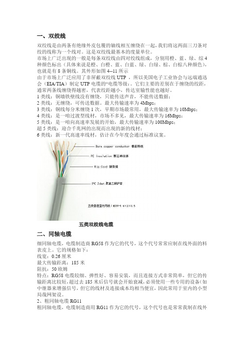
一、双绞线双绞线是由两条有绝缘外皮包覆的铀线相互缠绕在一起,我们将这两面三刀条对绞的线称为一个线对。
这是双绞线最基本的度量单位。
市场上广泛出现的一般是每条双绞线由四对绞线组成,分别用橙、蓝、绿、综4种颜色标出(具体来说是橙、白橙、蓝、白蓝、绿、白绿、棕、白棕八种颜色),也就是有8条铜线。
其外形如图4--11所示由于市场上广泛应用了非屏蔽双绞线UTP ,所以美国电子工业协会与远端通迅会(EIA/TIA)制定UTP电缆的“电缆等级:。
它们主要的差别在于缠绕的绞距,通常两条线缠绕得越密,代表绞距越小,传达室输性能也越好。
1类线:铜墙铁壁线没有缠绕,只能传送声音,不能传送数据;2类线:无缠绕,可传送数据。
最大传输速率为4Mbps;3类线:铜线每分米缠绕1次,早期市场最常用,最大传输速率为10Mbps;4类线:是一咱过渡型线材,市场不多见,最大传输速率为16Mbps;5类线:是一咱向高速率发展的开始,最大传输速率为100Mbps;超5类线:迎合千兆网的出现而出现的新的线材;6类线:新一代高速率线材,估计在今年度会通过标准议案。
五类双绞线电缆二、同轴电缆细同轴电缆,电缆制造商RG58作为它的代号,这个代号常常应制在线外面的料表皮上。
它的规格如下:线宽:0.26厘米最大传输距离:185米阻抗:50欧姆特点:RG58电缆较细、弹性好、容易安装,而且连接方式非常简单,但它的传输距离比较短,超过去185米后信号就会开始衰减,必须使用一些专用的设备(如中继器来增强信号,但它的线材及连接成本均相当便宜,因此常用于室内的小型局哉网架设。
2、粗同轴电缆RG11粗同轴电缆,电缆制造商用RG11作为它的代号,这个代号也是常常我制在线外面的普表皮上。
它的规格如下:线宽:1.27厘米最大传输距离:500米阻抗:50欧姆特点:线较粗,因此弹性较差,而且制作方式较为复杂,在室内安装时会遇到订烦;但它的最大传输距离远远大于RG58,可以达到点00米,学用于主干或建筑间连接。

2009年全国锐捷网络工程师认证(RCNA)上午题(习题集1)及答案[日期:2009-02-09] 来源:作者:[字体:大中小]1 . 如何将S2126G交换机的登陆密码配置为star?答案:CA、set password starB、login starC、enable secret level 1 0 starD、enable password star2 . RIP路由协议的周期更新的目标地址是? DA.172.16.0.1B.255.255.240.255C.255.255.255.240D.255.255.255.2553 . 如何使Star2624路由器启用IP路由? AA.router(config)#ip routingB.router(config)#ip inITC.router(config)#route ipD.router(config)#ip route4. 以下是配置PPP认证时通过debug ppp authentication得到的信息,请问该协议是几路握手?%UPDOWN:InterfaceSerial0,changedstate to up PPP Serial0:Send CHAP challenge id=2 to remote PPP Serial0:CHAP response id=2 receivedfrom user1 PPP Serial0;Send CHAP success id=2 to remote PPP Serial0;remote passed CHAP authentication.%UPDOWN:Lineprotocol on Interface Serial0.changed state to up AA.3B.4C.1D.25. 请说出OSI七层参考模型中哪一层负责建立端到端的连接?BA.会话层B.传输层C.网络层D.数据链路层E.应用层6. 请说出在数据封装过程中,至顶向下的协议数据单元(PDU)名字: BA.数据流、数据段、数据帧、数据包、比特B.数据流、数据段、数据包、数据帧、比特C.数据帧、数据流、数据段、数据包、比特D.比特、数据帧、数据包、数据段、数据流7. 去年你的公司10BASE-T网络增加了55台工作站。

®Recent developments in electronic equipment have shown the following trends:•Increasing demands for numerical control machines,robotics and technically advanced appliances are requiring p rogressive electronic technologies.•When employing integrated circuit and microcomputertechnology, today’s equipment is required to perform multifunctions in limited size.•The denser the installation of components, the morethe components must be miniaturized and of lighter weight.As a result, the following problems arise:•Functional limits of magnetic relays and switcheshave narrowed due to increasing contact amperage.•Miniaturization of electronic components has reducedtheir dielectric strength.•Circuit noise has increased as a result of the coexistenceof signal and power lines.•Safety standards for electronic equipment and componentshave become increasingly restrictive.Some key factors affecting circuit performance are:•Arcing between relay and switch contacts cause pittingand whiskers resulting in premature contact failure.•Contact arcing results in high frequency noise andabnormal high voltages.•The generation of back electromotive force (EMF) is due tothe inductance of loads present.•The occurrence of high frequency noise is the result ofcontact chatter in magnetic relays and switches.Back EMF, due to inductance, affects Silicon Control Rectifiers (SCRs) and Solid-State Relays (SSRs) and can result in the breakdown of other semiconductor devices. Power line surges must also be carefully considered. Either may be a contributing factor in equipment malfunctions, failures and in extreme cases of fire and/or electrical shock.T o illustrate these factors, consider that relay contact chatter is capable of inducing oscillations of several KHz, contact a rcing frequencies of several MHz and amplitudes 10 to 20times normal circuit voltages. Voltage surges from external sources may approach thousands of volts.To protect electronic equipment against costly failure s or malfunctions, Electrocube has developed advanced components to suppress contact arcing and filter unwanted electrical noise.I N T R O D U C T I O N T O R C N E T W O R K SG E N E R A L C O N S T R U C T I O NS A F E T Y S TA N D A R D SA P P L I C AT I O N SC U S T O MDE S I G N SRC Networks are easily selectable electronic components designed to prevent or substantially minimize the occurrence of arcing and noise generation in relay and switch contacts.RC Networks consist of specially designed capacitors and resistors connected in series. Spark discharges and induced noise are absorbed over a wide range by the accumulation characteristic and impedance of the capacitor, while the RC time constant delays and averages surge voltage and oscillations.RC Networks must have the capacity to store surge voltages and current energy and afford protection against inductively induced potentials. The dielectric material of Electrocube’s capacitors, used in RC Networks, affords a very high degree of voltage withstand strength. All resistors are non-inductive types to insure a high degree of protection against pulse potentials. To provide additional protection for equipment and users, especially when these components are used in their applications, all Electrocube RC Networks are packaged in cases which meet or exceed the flammability requirements of UL94VO.Electrocube’s RC Networks are UL and UL C approved.Self-declaration of CE mark is available upon request.•P rotection for contacts and from noise during switchingoperations of equipment such as radio, TV, copiers,mixers, coffee grinders, washing machines, dryers, tool machine equipment,packaging machinery, etc.•Protection of electronic instruments during operation ofrelays, solenoids, motors, etc.•Electrical noise protection of semiconductor devicesduring control of triacs, thyristors, motors, welders,illumination equipment, etcElectrocube offers many years of experience in the design and manufacture of standard RC Networks, as well as special units to meet customer requirements. For custom applications,consult the factory direct to assist in the design, production and delivery of your special needs.®CIRCUIT ACTIV ATION RESISTORTIMES/MINUTE WAT TA GE1-31/24-516-9210-155>1510E F F E C T O F R C N E T W O R K S A P P L I C AT I O N E X A M P L E SD E T E R M I N I N G R C VA L U EAt the moment of switch opening, the RC combinationabsorbs and suppresses the energy of the arc by letting itbypass the switch.The RC combination absorbs the high frequency oscillationscaused by mechanical vibrations such as relay contact chattering.Similarly, the oscillations created by arcing are also averaged andsuppressed by the RC combination re g a rdless of their origin.With back electromotive force due to inductance, the surg evoltage peak is suppressed by conducting it through the RCcircuit on the low impedance side. the peak is absorbed by thecapacitance of RC. The waveform is averaged and smoothedby the time constant of the RC; thus generated noise iseliminated or substantially minimized.The RC combination allows the dv/dt of the “on” and “off”operation of thyristors or similar devices to decrease; thus surg evoltages are suppressed and semiconductor elements areprotected. Even in the case of zero crossing circuits, such as ACcircuits, protection is necessary since harmonic noise occurswhen there is a gap between phases of current and voltage ofthe load circuit.In general, the calculated RC value is difficult to determineusing the following formula. This is due to contributing factorssuch as equipment wiring and component locations which canvary from machine to machine.The best way to determine the values needed is to obtain astorage oscilloscope and match combinations of resistors andcapacitors while viewing the amount of spike reduction on theoscilloscope. The user should change the combination of R & Cuntil the optimum spike reduction is achieved.Electrocube has determined that the best overall combination is0.47-.50 Mfd @ 220W. This combination seems to work for 90%of the applications. The voltage should be selected for thenormal DC or AC voltages, however, the designer must takeinto consideration the peak voltages involved.The resistor wattage depends upon the number of times perminute the circuit is activated. As a general rule of thumb, thefollowing chart should be considered.The chart and formula are guidelines to give the user a startingpoint from which to work. The final selection must be evaluatedin the application to determine its acceptability. DAMPING OSCILLATIONBACK ELECTROMOTIVE FORCE SUPPRESSIONDV/DT SUPPRESSIONARC SUPPRESSIONStandard example in AC circuitsStandard example in DC circuitsStandard example in DC circuits For phase control circuits employingSCR or TRIAC, etc.E®RESISTANCE PEAKCAPACITY OHMS RATED PULSE A B C #20 AWG TINNED #18 AWG MTW MFD 10% VOLTAGE VOLTAGE IN.IN.IN. SOLID WIRE 0.5±10%22300V 1.00.38.63RG1780-10.5±10%33300V 1.00.38.63RG1780-20.5±10%47300V 1.00.38.63RG1780-30.5±10%68300V 1.00.38.63RG1780-40.5±10%82300V 1.00.38.63RG1780-50.5±10%100300V 1.00.38.63RG1780-60.5±10%150300V 1.00.38.63RG1780-70.5±10%220300V 1.00.38.63RG1780-80.5±10%330300V 1.00.38.63RG1780-90.5±10%470300V 1.00.38.63RG1780-100.5±10%680300V 1.00.38.63RG1780-111.0±10%22300V 1.00.50.75RG1781-11.0±10%33300V 1.00.50.75RG1781-21.0±10%47300V 1.00.50.75RG1781-31.0±10%68300V 1.00.50.75RG1781-41.0±10%82300V 1.00.50.75RG1781-51.0±10%100300V 1.00.50.75RG1781-61.0±10%150300V 1.00.50.75RG1781-71.0±10%220300V 1.00.50.75RG1781-8300V 1.00.50.75RG1781-9300V 1.00.50.75RG1781-10300V 1.00.50.75RG1781-11900V 1.00.38.63RG1782-1900V 1.00.38.63RG1782-2900V 1.00.38.63RG1782-3900V 1.00.38.63RG1782-4900V 1.00.38.63RG1782-5900V 1.00.38.63RG1782-6900V 1.00.38.63RG1782-7900V 1.00.38.63RG1782-8900V 1.00.38.63RG1782-9900V 1.00.38.63RG1782-10900V 1.00.38.63RG1782-11900V 1.00.50.75RG1783-1900V 1.00.50.75RG1783-2900V 1.00.50.75RG1783-3900V 1.00.50.75RG1783-4900V 1.00.50.75RG1783-5900V 1.00.50.75RG1783-6900V 1.00.50.75RG1783-7900V 1.00.50.75RG1783-8900V 1.00.50.75RG1783-9900V 1.00.50.75RG1783-10900V 1.00.50.75RG1783-11900V 1.25.58.84RG1784-1900V 1.25.58.84RG1784-2900V 1.25.58.84RG1784-3900V 1.25.58.84RG1784-4900V 1.25.58.84RG1784-5900V 1.25.58.84RG1784-6900V 1.25.58.84RG1784-7900V 1.25.58.84RG1784-8900V 1.25.58.84RG1784-9900V 1.25.58.84RG1784-10900V1.25.58.84RG1784-11Available wire leads. 200VDC OR 125VACAll resistors are rated 1/2 watt.Maximum peak surge voltage is 11/2 times the rated DC voltage.For other lead lengths and resistor values,consult factory.*Networks with MTW leads have nominal lead spacing.Temperature range: -40°to +80°C.(Solid Leads)®RG1676 RESISTANCE TOLERANCE POWER CAPACITY TOLERANCE VDC VAC METAL OXIDE RG1676 LEAD CIRCUIT PN. OHMS % WATTS MFD % VOLTS VOLTS VARISTOR PN. LENGTH (IN.) NO.RG1676-11001010 1.00101000480N/A 241RG1676-21001010.50101000480N/A 241RG1676-3 10 10 2 1.00 10 600 250 N/A 25 1RG1676-4 220 10 10 .47 10 600 250 N/A 25 1 RG1676-5 220 10 1 .50 10 600 250 N/A 25 1RG1676-6 100 10 1 .10 10 2000 480 N/A 24 1RG1676-7100103 2.0010600250N/A 251RG1676-8 100 10 2 .47 10 600 250 N/A 25 1RG1676-9220101.4710600250N/A 251RG1676-10220105 2.0010600250N/A 251RG1676-11220101.5010600120V130LA1242RG1676-12220102.50101000480N/A 241RG1676-13220101.47101000480N/A 241RG1676-14220101.4710600120V130LA1242RG1676-15220101 1.0010600250N/A 251RG1676-162201010.50101000480N/A 241RG1676-17100102 1.0010600250N/A 251RG1676-18220105.47101000480N/A 481RG1676-19220102 1.0010400120N/A 241RG1676-20100102 2.0020600250N/A 181RG1676-2110105 1.00101000480N/A 241RG1676-22220102.5010400120N/A 241RG1676-2322010.5.5010400120N/A 241RG1676-242201010.50101000480N/A 361.5010400120N/A 361.10101000480N/A 121.10102000480N/A 121.10101000250V250LA2242.50101000480N/A 241.4710600250V300LA2122241241241481361V130LA11202The RG1676 is designed for arc and noise suppression in heavy duty applications requiring greater magnitudes of power dissipation. Due to its mass and weight,mounting holes are provided at either end of the case to permit secure mounting to a chassis.Its configuration lends itself to stacking for maximum utilization of available space. Special lead lengths are available. Other values of wattage and resistance capacitance and voltage are also available.Maximum peak surge voltage is 11/2time the rated DC voltage.All leads #18 AWG MTW except -24 through -33 and -61 which are 16# AWG MTW.RC NetworksElectrocubeSingle Phase Heavy DutyCAPACITY MFD.RESISTANCEOHMS 10%RATED VOLTAGEPEAK PULSE VOLTAGEL mmH mmT mmLS mmLd 1 / Ld 2mmPART NUMBERAll resistors are rated ½ wattMaximum peak surge voltage is 1 ½ times the rated DC voltage.`For other lead lengths and resistor values, consult factory.Temperature range: -40˚ C to +85˚ C1.0 ± 20% 22 200 VDC / 125 VAC 300V 36.8 17.0 10.0 30 ± 2 0.8 / 0.7RG2675-1 1.0 ± 20% 33 200 VDC / 125 VAC 300V 36.8 17.0 10.0 30 ± 2 0.8 / 0.7 RG2675-2 1.0 ± 20% 47 200 VDC / 125 VAC 300V 36.8 17.0 10.0 30 ± 2 0.8 / 0.7 RG2675-3 1.0 ± 20% 68 200 VDC / 125 VAC 300V 36.8 17.0 10.0 30 ± 2 0.8 / 0.7 RG2675-4 1.0 ± 20% 82 200 VDC / 125 VAC 300V 36.8 17.0 10.0 30 ± 2 0.8 / 0.7 RG2675-5 1.0 ± 20% 100 200 VDC / 125 VAC 300V 36.8 17.0 10.0 30 ± 2 0.8 / 0.7 RG2675-6 1.0 ± 20% 150 200 VDC / 125 VAC 300V 36.8 17.0 10.0 30 ± 2 0.8 / 0.7 RG2675-7 1.0 ± 20% 220 200 VDC / 125 VAC 300V 36.8 17.0 10.0 30 ± 2 0.8 / 0.7 RG2675-8 1.0 ± 20% 330 200 VDC / 125 VAC 300V 36.8 17.0 10.0 30 ± 2 0.8 / 0.7 RG2675-9 1.0 ± 20% 470 200 VDC / 125 VAC 300V 36.8 17.0 10.0 30 ± 2 0.8 / 0.7 RG2675-10 1.0 ± 20% 680 200 VDC / 125 VAC 300V 36.8 17.0 10.0 30 ± 2 0.8 / 0.7 RG2675-11 .15 ± 20% 22 600 VDC / 250 VAC 900V 27.5 17.5 10.5 20 ± 2 0.8 / 0.7 RG2676-1 .15 ± 20% 33 600 VDC / 250 VAC 900V 27.5 17.5 10.5 20 ± 2 0.8 / 0.7 RG2676-2 .15 ± 20% 47 600 VDC / 250 VAC 900V 27.5 17.5 10.5 20 ± 2 0.8 / 0.7 RG2676-3 .15 ± 20% 68 600 VDC / 250 VAC 900V 27.5 17.5 10.5 20 ± 2 0.8 / 0.7 RG2676-4 .15 ± 20% 82 600 VDC / 250 VAC 900V 27.5 17.5 10.5 20 ± 2 0.8 / 0.7 RG2676-5 .15 ± 20% 100 600 VDC / 250 VAC 900V 27.5 17.5 10.5 20 ± 2 0.8 / 0.7 RG2676-6 .15 ± 20% 150 600 VDC / 250 VAC 900V 27.5 17.5 10.5 20 ± 2 0.8 / 0.7 RG2676-7 .15 ± 20% 220 600 VDC / 250 VAC 900V 27.5 17.5 10.5 20 ± 2 0.8 / 0.7 RG2676-8 .15 ± 20% 330 600 VDC / 250 VAC 900V 27.5 17.5 10.5 20 ± 2 0.8 / 0.7 RG2676-9 .15 ± 20% 470 600 VDC / 250 VAC 900V 27.5 17.5 10.5 20 ± 2 0.8 / 0.7 RG2676-10 .15 ± 20% 680 600 VDC / 250 VAC 900V 27.5 17.5 10.5 20 ± 2 0.8 / 0.7 RG2676-11 .25 ± 10% 22 600 VDC / 250 VAC 900V 36.8 19.0 10.5 30 ± 2 0.8 / 0.7 RG2677-1 .25 ± 10% 33 600 VDC / 250 VAC 900V 36.8 19.0 10.5 30 ± 2 0.8 / 0.7 RG2677-2 .25 ± 10% 47 600 VDC / 250 VAC 900V 36.8 19.0 10.5 30 ± 2 0.8 / 0.7 RG2677-3 .25 ± 10% 68 600 VDC / 250 VAC 900V 36.8 19.0 10.5 30 ± 2 0.8 / 0.7 RG2677-4 .25 ± 10% 82 600 VDC / 250 VAC 900V 36.8 19.0 10.5 30 ± 2 0.8 / 0.7 RG2677-5 .25 ± 10% 100 600 VDC / 250 VAC 900V 36.8 19.0 10.5 30 ± 2 0.8 / 0.7 RG2677-6 .25 ± 10% 150 600 VDC / 250 VAC 900V 36.8 19.0 10.5 30 ± 2 0.8 / 0.7 RG2677-7 .25 ± 10% 220 600 VDC / 250 VAC 900V 36.8 19.0 10.5 30 ± 2 0.8 / 0.7 RG2677-8 .25 ± 10% 330 600 VDC / 250 VAC 900V 36.8 19.0 10.5 30 ± 2 0.8 / 0.7 RG2677-9 .25 ± 10% 470 600 VDC / 250 VAC 900V 36.8 19.0 10.5 30 ± 2 0.8 / 0.7 RG2677-10 .25 ± 10% 680 600 VDC / 250 VAC 900V 36.8 19.0 10.5 30 ± 2 0.8 / 0.7 RG2677-11 .50 ± 20% 22 600 VDC / 250 VAC 900V 36.8 23.3 15.0 30 ± 2 0.8 / 0.7 RG2678-1 .50 ± 20% 33 600 VDC / 250 VAC 900V 36.8 23.3 15.0 30 ± 2 0.8 / 0.7 RG2678-2 .50 ± 20% 47 600 VDC / 250 VAC 900V 36.8 23.3 15.0 30 ± 2 0.8 / 0.7 RG2678-3 .50 ± 20% 68 600 VDC / 250 VAC 900V 36.8 23.3 15.0 30 ± 2 0.8 / 0.7 RG2678-4 .50 ± 20% 82 600 VDC / 250 VAC 900V 36.8 23.3 15.0 30 ± 2 0.8 / 0.7 RG2678-5 .50 ± 20% 100 600 VDC / 250 VAC 900V 36.8 23.3 15.0 30 ± 2 0.8 / 0.7 RG2678-6 .50 ± 20% 150 600 VDC / 250 VAC 900V 36.8 23.3 15.0 30 ± 2 0.8 / 0.7 RG2678-7 .50 ± 20% 220 600 VDC / 250 VAC 900V 36.8 23.3 15.0 30 ± 2 0.8 / 0.7 RG2678-8 .50 ± 20% 330 600 VDC / 250 VAC 900V 36.8 23.3 15.0 30 ± 2 0.8 / 0.7 RG2678-9 .50 ± 20% 470 600 VDC / 250 VAC 900V 36.8 23.3 15.0 30 ± 2 0.8 / 0.7 RG2678-10 .50 ± 20% 680 600 VDC / 250 VAC 900V 36.8 23.3 15.0 30 ± 2 0.8 / 0.7 RG2678-11®®RC NETWORKSIN DIN RAIL ENCLOSURES•Single-phase and three-phase Delta and WYE configurations •Compatible with DIN Rails 46277-1 and 46277-3•Enclosures meet UL-94VO flammability requirements •Screw terminations for convenience•Ideal for control applications, large scale instrumentation and automation •Space-saving•Reduced installation time •Custom configurations availableRG2377-1RG2406-12210480RG2377-2RG2406-23310480RG2377-3RG2406-34710480RG2377-4RG2406-46810480RG2377-5RG2406-58210480RG2377-6RG2406-610010480RG2377-7RG2406-715010480RG2377-8RG2406-822010480RG2377-9RG2406-933010480RG2377-10RG2406-1047010480RG2377-11RG2406-1168010480DELTA WYE RESISTOR CAPACITOR VOLTSPART NO. PART NO. (OHM±10%) WATTS MFD (VAC)®SERIES SELECTIOND A S H N O .O-1 -2-3-4-5-6-7-8-9-10-11RESISTOR SELECTIONH O W T O O R D E RSERIESVA CYDVARISTORRG2561660no yes no RG2562660yes no no RG2563660no yes yes RG2564660yes no yes RG2571480no yes no RG2572480yes no no RG2573480no yes yes RG2574480yesnoyesRG2564 - 8 - 12S E R I E S (See Series Selection Chart)CAPACITOR: 0.47 µF , ±10%RESISTOR: Ohms ±5%, 10 Watt CASE: ABS Plastic/Epoxy FillRESISTOR(See Resistor Selection Chart)LEAD LENGTH (INCHES)(Note: standard lead length is 10” ±.010”;specify lead lengths in 1” increments)F E AT U R E S :•480 and 600 VAC ratings •Three-phase Delta and WYE configurations •Varistor options available •Capacitance: 0.47 µF , ±10%tolerance •Resistance: 22 to 680 ohms,±5%, 10 watt •Enclosure meets UL-94VO flammability requirements •Standard lead length is 10”•Custom configurationsElectrocube, the largest U.S. manufacturer of arc suppressing resistor-capacitor (RC) networks has expanded its capabilities into the industrial motor and controls market with the introduction of its new series of three-phase high voltage RC networks.Designated as the RG2561 through RG2564 (660 VAC) and RG2571through RG2574 (480 VAC) Series, these new product lines are designed to meet the exacting electrical and physical requirements of heavy duty industrial applications.The creation of this new product line complements Electrocube’s extensive lines of single-phase and three-phase RC networks for electronic instrumentation and control. These RC networks allow Electrocube to continue its role as a leader in the design, development and manufacture of the highest quality RC networks in the United States.Consult Electrocube for all of your RC networks and precision film capacitor requirements.All dimensions are in inches.。

RG-FC 系列光纤收发器文档版本 :V1.10版权声明copyright © 2020锐捷网络保留对本文档及本声明的一切权利。
未得到锐捷网络的书面许可,任何单位和个人不得以任何方式或形式对本文档的部分内容或全部进行复制、摘录、备份、修改、传播、翻译成其他语言、将其全部或部分用于商业用途。
以上均为锐捷网络的商标。
本文档提及的其他所有商标或注册商标,由各自的所有人拥有。
免责声明您所购买的产品、服务或特性等应受商业合同和条款的约束,本文档中描述的全部或部分产品、服务或特性可能不在您的购买或使用范围之内。
除非合同另有约定,锐捷网络对本文档内容不做任何明示或默示的声明或保证。
由于产品版本升级或其他原因,本文档内容会不定期进行更新。
锐捷网络保留在没有任何通知或者提示的情况下对文档内容进行修改的权利。
本手册仅作为使用指导。
锐捷网络在编写本手册时已尽力保证其内容准确可靠,但并不确保手册内容完全没有错误或遗漏,本手册中的所有信息也不构成任何明示或暗示的担保。
前言感谢您使用锐捷网络产品,本手册为您提供了详细的硬件安装指南。
使用范围本手册主要介绍了产品在功能上和物理上的一些特性,提供了安装步骤、故障排除、技术规格,以及电缆和连接器的规格和使用准则。
适用于想对上述内容进行了解且在安装和维护网络硬件方面具有一定经验的用户。
同时假定该款产品的用户熟知相关术语和概念。
技术支持⏹锐捷睿易官方网站:https:///⏹锐捷睿易在线客服:/?p=smb⏹锐捷网络官方网站服务与支持版块:https:///service.aspx⏹7天无休技术服务热线:4001-000-078⏹锐捷睿易技术论坛:/⏹常见问题搜索:/service/know.aspx⏹锐捷睿易技术支持与反馈信箱:*********************.cn⏹锐捷网络服务公众号:【锐捷服务】扫码关注文档格式约定本书采用各种醒目标志来表示在操作过程中应该特别注意的地方,这些标志的意义如下:注意、警告、提醒操作中应注意的事项。
Part Number: 9913F7Low Loss 52 Ohm, RG8, Flexible 10 AWG Stranded BC, Foil + Braid, Belflex®JacketProduct DescriptionLow Loss, RG-8/U type, 10 AWG stranded (7x19) .108" bare copper conductor, gas-injected foam HDPE insulation, Duobond® II, tinned copper braid shield (95% coverage), Belflex® jacket.Technical SpecificationsProduct OverviewPhysical Characteristics (Overall)ConductorInsulationOuter Shield MaterialOuter Jacket MaterialElectrical CharacteristicsConductor DCRCapacitanceInductanceImpedanceHigh Frequency (Nominal/Typical)Frequency [MHz]Nom. Insertion Loss10 MHz0.6 dB/100ft50 MHz 1.1 dB/100ft100 MHz 1.5 dB/100ft200 MHz 2 dB/100ft400 MHz 3 dB/100ft700 MHz 4 dB/100ft900 MHz 4.7 dB/100ft1000 MHz 5 dB/100ft2000 MHz7.5 dB/100ft2250 MHz8 dB/100ft3000 MHz9.8 dB/100ft4000 MHz12.1 dB/100ftDelayNominal Delay Nominal Velocity of Propagation (VP) [%]1.2 ns/ft85 %High FreqFrequency [MHz]Max. Insertion Loss (Attenuation)10 MHz0.7 dB/100ft50 MHz 1.3 dB/100ft100 MHz 1.8 dB/100ft200 MHz 2.4 dB/100ft400 MHz 3.4 dB/100ft700 MHz 4.6 dB/100ft900 MHz 5.3 dB/100ft1000 MHz 5.6 dB/100ft2000 MHz8.2 dB/100ft2250 MHz8.9 dB/100ft3000 MHz10.9 dB/100ft4000 MHz13.6 dB/100ftPower RatingFrequency [MHz]Max. Power Rating [W]Nominal Power Rating [W]5 MHz3,217 W3,217 W10 MHz2,681 W2,681 W50 MHz1,463 W1,463 W100 MHz1,073 W1,073 W200 MHz805 W805 W400 MHz575 W575 W700 MHz424 W424 W1,000 MHz350 W366 W1,500 MHz278 W350 W2,000 MHz237 W278 W3,000 MHz188 W252 W4,000 MHz157 W237 W2,500 MHz210 W3,000 MHz188 W4,000 MHz157 WVoltageNon-UL Voltage Rating300 V RMSVSWRFrequency [MHz]5-2250 MHzElectrical Characteristics Notes:Actual Impedance specification is 51.5 +/- 2 ohms. Temperature RangeNon-UL Temp Rating:80°COperating Temp Range:-40°C To +80°CMechanical CharacteristicsBulk Cable Weight:94 lbs/1000ftMax Recommended Pulling Tension:210 lbsMin Bend Radius/Minor Axis: 3 inStandardsRG Type:8/U TypeApplicable Environmental and Other ProgramsEU Directive 2000/53/EC (ELV):YesEU Directive 2003/96/EC (BFR):YesEU Directive 2011/65/EU (ROHS II):YesEU Directive 2012/19/EU (WEEE):YesEU Directive 2015/863/EU:YesEU Directive Compliance:EU Directive 2003/11/EC (BFR)EU CE Mark:NoEU RoHS Compliance Date (yyyy-mm-dd):2004-01-01CA Prop 65 (CJ for Wire & Cable):YesMII Order #39 (China RoHS):YesSuitabilitySuitability - Indoor:YesPlenum/Non-PlenumPlenum (Y/N):NoPart NumberVariantsItem #Color Footnote9913F7 B59100Black, Matte C9913F7 B591000Black, Matte C9913F7 B59250Black, Matte C9913F7 B59500Black, Matte CFootnote: C - CRATE REEL PUT-UP.Product NotesNotes:Low Loss, High Flex© 2019 Belden, IncAll Rights Reserved.Although Belden makes every reasonable effort to ensure their accuracy at the time of this publication, information and specifications described here in are subject to error or omission and to change without notice, and the listing of such information and specifications does not ensure product availability.Belden provides the information and specifications herein on an "ASIS" basis, with no representations or warranties, whether express, statutory or implied. In no event will Belden be liable for any damages (including consequential, indirect, incidental, special, punitive, or exemplary damages) whatsoever, even if Belden has been advised of the possibility of such damages, whether in an action under contract, negligence or any other theory, arising out of or in connection with the use, or inability to use, the information or specifications described herein.All sales of Belden products are subject to Belden's standard terms and conditions of sale.Belden believes this product to be in compliance with all applicable environmental programs as listed in the data sheet. The information provided is correct to the best of Belden's knowledge, information and belief at the date of its publication. This information is designed only as a general guide for the safe handling, storage, and any other operation of the product itself or the one that it becomes a part of. The Product Disclosure is not to be considered a warranty or quality specification. Regulatory information is for guidance purposes only. Product users are responsible for determining the applicability of legislation and regulations based on their individual usage of the product.。