大众汽车自学手册SSP_5
- 格式:pdf
- 大小:6.48 MB
- 文档页数:31
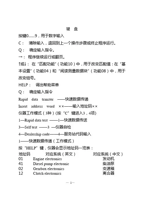
键盘按键0……9,用于数字输入C:清除输入,退回到上一个操作步骤或终止程序运行。
Q:确定输入指令。
→:程序继续运行或翻页。
↑或→:在“匹配功能”(功能10)中,用于改变匹配值:在“基本设置”(功能04)和“阅读测量数据块”(功能08)中,用于改变组号。
HELP:调出帮助菜单Q:确定输入指令Rapid data transter ——快速数据传递Insert address word ××——输入地址码××仪器工作模式(3种)〈按“C”键进入3,4项〉1—Rapid data test ——1—快速数据传送3—Self test ——3 —仪器自检4—Dealership code——4—服务站代码输入1——快速数据传递(工作模式)按“HELP”键,仪器会显示地址码一览表:地址码对应系统(英文)对应系统(中文)01 Engine electronics 发动机41 Diesel pump electronic 柴油泵02 Gearbox electronics 变速箱12 Clutch electronics 离合器—1—地址码对应系统(英文)对应系统(中文)03 Brake electronics 刹车系统14 Wheel danping electronics 车轮减振24 Drive slip control 驱动防滑15 Airbag 安全气囊26 Electril roof contral 滑动天窗17 Dash panel insert 仪表板08 AC/heating electronics 空调25 Immobilizer 防盗00 Autonatie test sequence 自动检测程序;自动查询和显示车辆所有电器系统的故障。
检测发动机为例:输入“01”显示Rapid data transfer 2 (快速数据传递2)01—Engine electronics(01—发动机)按“Q”显示4A0 907 473A 2.6L V6 MPFI D01 →coding(编码)00001 WSC63880显示说明:4A0 907 473A——控制单元零件号2.6L——发动机排量V6——喷油系统(V型6缸)MPFI——多点燃油喷射系统D01——控制单元软件版本00001——控制单元编码按“→”键进入发动机系统的功能选择,显示:Rapid data transfer help— 2 —(快速数据传递)(帮助)Select function ××(选择功能××)功能一览表01 Interrogate control unitversion 查询控制单元型号02 Interrogate faultmemory 查询故障记忆03 Final control diagnosis 执行元件诊断04 Basic setting 基本调整05 Erase fanlt memory 清除故障记忆06 End output 中断输出07 Code control unit 给控制单元编码08 Read measuring Value block 阅读测量数据块09 Read indiridual measuring value 阅读单独测量数据块10 Adaptation 匹配11 Log—in 密码输入选择功能“02”→“Q”→显示控制单元存储的故障信息。
Contents:General function description Page 3Steering column electronicsmoduleCoil spring moduleSteering angle sensor Page 4Steering column switchCCS switch Page 6Ignition starter lock administrationElectronic steering wheel moduleSelf-diagnosis Page 7This trainer information is structured forself study programme 254 – Audi A4 2001and is not aWorkshop Manual!For maintenance and repair workplease use the currenttechnical literature.Function descriptionThe steering column electronics–J527 takeover the tasks of the steering column switchmodule and consists of the following:•Wattless signal processing of thesteering column switches – also CCS,•Evaluation of the ignition starter switch•Administration of the multi-function andtiptronic steering wheel•Control of the steering wheel heating•Diagnosis of all steering wheel andsteering column switch functions•Evaluation of the steering angle sensorand information transfer via the driveCAN busAll the individual components of the steeringcolumn switch module can be replacedindividually.Steering column electronicsThree steering column electronics versionsare available with different functions•Low-line (standard)- Turn signal switch recognition- Wiper switch recognition- On-board computer control- Horn switch- Steering angle determination•Mid-line with additional- CCS – switch recognition- Multi-function steering wheel control- Tiptronic function in steering wheel•High-line with additional- steering wheel heatingDue to the various wirings of the processor,refitting of the steering wheel is notstraightforward. The correct modulecombination must be therefore be checkedbeforehand.Coil spring moduleThree different versions of the module areavailable, depending on the steering wheelelectronics module.There is a coil spring module with1 band > airbag and horn only (standard)2 bands>with steering wheel operationfor tiptronic/multi-functionbuttons4 bands> with steering wheel heating Steering angle sensorThe visual unit of the steering wheel sensor islocked into the coil spring module and cannotbe replaced individually.Steering column switchThe relevant switch position is recognised viathe steering column electronicsmicroprocessor due to the voltage drop at thepull-up resistors.The switching current of the wattless switchesis between 10 and a maximum of 35 mA.The relevant switches can be checked via themeasured value blocks of the self diagnosisor via resistance measurement.Wiper switch PIN 1+6Resistance values (Tolerances are not taken into account)Rest position8703 O Step 1332 O Flick wipe332 O Intermittent1013 O Step 22513 O Washer switchPIN 1+5Rest position8703 O Windscreen washing332 O Rear window wiping1013 O Rear window washing2513 O Interval wipe potiPIN 1+2Switch defective9070 O Step 1240 O Step 2630 O Step 31380 O Step 42880 O On-board computerswitchPIN 1+3Rest position8703 O Reset332 O Cursor up1013 O Cursor down2513 OTurn signal PIN 1+6Resistance values (Tolerances are not taken into account)Rest position0 O Right2131 O Left681 O Main beamPIN 1+5Rest position0 O Headlamp flasher2131 O Main beam681 O Alarm for taxisPIN 1+3Rest position8O Pressed0 O Radio for taxisPIN 1+2Rest position / Switchdefective8O Pressed0 OCCS switch horizontal PIN 1+5Resistance values (Tolerances are not taken into account)Rest position 8371 O Resume2181 O Soft off681 O CCS switch, verticalPIN 1+6Rest position8371 O Accelerate2181 O Decelerate681 O CCS switchEngaged offPIN 1+7Rest position8O Engaged OFF 0 O CCS switchSet buttonPIN 1+2Rest position8O Set pressed 0 OSteering wheel heatingThe steering wheel heating is activated via the seat heating switch on the driver’s side independent of the heating level. The switch-on information is transferred by the climate control unit via the convenience CAN bus.When switched on, the heater is supplied with power for 2 seconds and is then set to a temperature of 21°C via an NTC in the steering wheel crown.Tiptronic buttonsWhen engaging the gear lever in the tiptronic gate, an earth potential is applied to the switch. The locating light is dimmed with the terminal 58s.Dimming of the switch lights is via theconvenience CAN bus from the dash panel insert. Testing via self diagnosis is possible.Self diagnosisAddress word16 – steering wheel electronics with ignition ON.Despite answerback in the diagnosis tester the steering wheel electronics respond.The actual steering wheel electronics module is interrogated via the steering wheel electronics.The self diagnosis is performed via the CCE, i.e. if the steering wheel electronics module isdiagnosed it is carried out via the convenience CAN bus > steering wheel electronics > steering column electronics > CCE > K-wire > diagnosis tester.Central Convenience Electronic (CCE)Steering column switch moduleSteering wheelmoduleKWP1281 via K-wireKWP1281via K-CANasynchronous interfaceEntry into fault memory (02)If the faultis displayed, adaption of the steeringcolumn electronics to the vehicle must be performed.Refer to …Adaption“Final control diagnosis test (030)In the final control diagnosis test the following functions can be activated depending on the available version.DisplayFunctionL o w -L i n e M i d -L i n e H i g h -L i n e Illumination / Switch and instrumentsLocating light is switched onX X XHeated steering wheelSteering wheel heating is switched onX Radio louder Radio volume increases X X Radio quieter Radio volume decreases X X Radio station search, upwards Upward search is started X X Radio station search,downwardsDownward search is started X X Telephone memory Telephone memory isdisplayedX X Next telephone memory Next telephone memory isdisplayedX X End Final control diagnosis test iscompletedX X X01794Control unit – wrong chassis numberCode (07)Measured value blocks (08)A chassis number is stored in channel 81 and is used for anti-theft protection.Please observe the procedure as described in …Adaption“.Input signals001Ignition starter switchTurn signalHeadlamp flasherMain beamsVersionsCodeUnallocated = 0XSteering wheel version0 = Standard steering wheel 1 = 3-spoke sports steering wheel2 = Multi-function steering wheel with radio control3 = Multi-function steering wheel with radio/telephone control4 = Multi-function steering wheel with radio/telephone and voice control system XSteering wheel version 0 = no tiptronic on steering wheel, no steering wheel heating1 = Tiptronic on steering wheel2 = Steering wheel heating3 = Tiptronic on steeringwheel with steering wheel heatingXOptional extras0 = No on-board computer no CCS1 = On-board computer (FIS)2 = CCS4 = On-board computer and CCS XRear wiper 1 = without 2 = withX0/1 > P-Contact0/1 > S-Contact (86s)0/1 > T. 750/1 > T. 150/1 >T. 50not actuatedleftrightnot actuatedactuatednot actuatedactuated002Horn Wiper,front Intermittent Wiper,frontnot actuated actuatednot actuatedIntermittent stepStep 1 (flick wipe also)Step 2Step 1Step 2Step 3Step 4not actuatedactuated003Wiper,rear:Wiper,rear:On-board computer(FIS)Unallocatednot installed not actuated actuated not installednot actuatedactuatednot installednot actuatedReset switch (645)On switch (643)Switch (644)Mid and high-line onlyCCS switch unit004CCSON/OFFCCS set CCS currently unallocatedON OFF not actuatedactuatednot actuatedacceleratedeceleratestored offReactivationSteering wheel module – tiptronic steering wheel005Switch down Switch up Steering wheelheatingTemp sensornot installed not actuated actuated not installednot actuatedactuatednot installedOnOffnot installedxx °CSteering wheel module – MFS (multi-function steering wheel)006MFLCommunicationMFLVersionFault inMFS?OK Not OK …Version…YesNo007MF button1MF button2MF button3MF button4not actuated actuated not actuatedactuatednot actuatedactuateddisabledenabledMWB 007/008F – door 0 F – door 1BF – door 0BF – door 1not installedDoor rl 0Door rl 1not installedDoor rr 0Door rr 1127Radio Telephone Language inputRadio 0 Radio 1Telephone 0Telephone 1Language 0Language 1Adaption (10)When installing a component that has already been used in another vehicle, adaption must be performed, as the chassis number is stored in channel 81 of the measured value block.The adaption must be activated using a control unit code (steering column electronics = 111).If the code number has been entered incorrectly 3 times in a row the adaption is blocked for a defined time frame.The …current“chassis number is transmitted by the dash panel insert via the convenience CAN bus after adaption has been carried out. When a new replacement part is used, this process is carried out automatically during initial operation.。
Service Training自学手册SSP 538双离合器变速器 0DD 结构和功能Golf GTE 上采用了一种新双离合器变速器。
由于这种变速器体积小巧,因此也可用在A0和B级车上。
双离合器变速器 0DD 在 Golf GTE上,是配合1,4 l-110 kW-TSI-发动机和75kW的驱动电机V141使用的,该变速器是专为这种驱动模式而设计的,可以让驾驶者在燃油最省的情况下获得极好的驾驶乐趣。
下面就具体讲述双离合器变速器0DD的结构和功能。
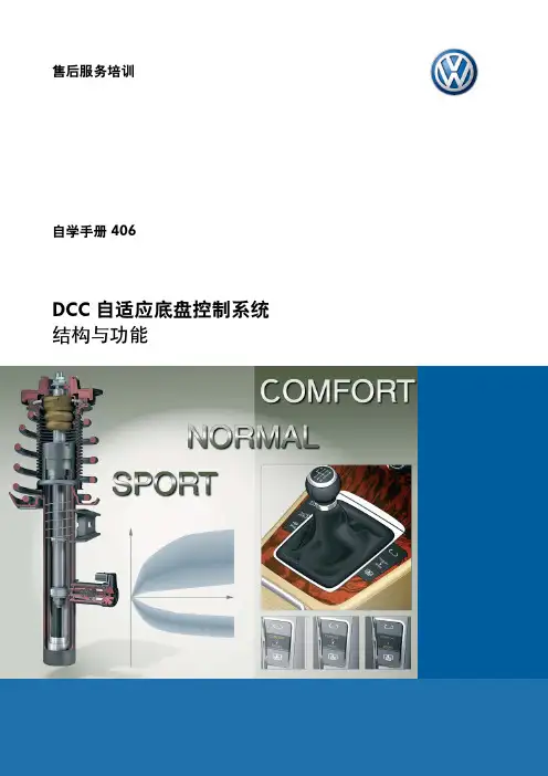
s538_035本自学手册讲述的是新技术的结构和功能! 最新的检查、调节和维修说明,请参阅相应的维修手册。
注意说明本手册的内容不再更新的了。
2一览引言. . . . . . . . . . . . . . . . . . . . . . . .. . . . . . .. . . . . . .. . . . . . . . . . . . . . . . . . . . . .4大众集团的双离合器变速器. . . . . . . . . . . . . . . . . . . . . . . . . . . . . . . . . . . . . . . 4 Golf GTE上的双离合器变速器0DD. . . . . . . . . . . . .. . . . . . . .. . . . . . . . . . . . 6混合动力模块. . . . . . . . . . . .. . . . . . . . . . . . . . . . . . . . . . . . . . . . . . . . . . . . . . . . .8结构一览. . . . . . . . . . . . . . . . . . . . . . . . . . . . . . . . . . . . . . . . . . . . . . .. .. . . . . . . 8离合器. . . . . . . . . . . . . . . . . . . . . . . . . . . . . . . . . . .. . . . . . . . . . . . . . . . . . . . . 9变速器. . . . . . . . . . . . . . . . . . . . . . . . . . . . . . . . . . . . . . . .. . . .. . . . . . . . . . . . . . .10结构一览. . . . . . . . . . . . . . . . . . . . . . . . . . . . . . . . . . . . . . . . . . . . . .. . . . .. . . . 10 输入轴 1 . . . . . . . . . . . . . . . . . . . . . . . . . . . . . . . . . . . . . . . .. . . . . . . . . . . . . . 12 输入轴 2 . . . . . . . . . . . . . . . . . . . . . . . . . . . . . . . .. . . . . . . . . . . . . . . . . . . . . . 13 输出轴 1 . . . . . . . . . . . . . . . . . . . . . . . . . . . . . . . . . . . . . . . . . . . . . . . . . . . . . . .14 输出轴 2 . . . . . . . . . . . . . . . . . . . . . . . . . . . . . . . . . . . . . . . . . . . . . . . . . . . . . . .15 换挡轴. . . . . . . . . . . . . . . . . . . . . . . . . . . . . .. . . . . .. . . . . . . . . . . . . . . . . . . . . .16 单锥面同步器. . . . . . . . . . . . . . . . . . . . . . . . . . . . . . . . . . . . . . . . . . . . . . . . . . . 18 离合器的相互配合. . . . . . . . . . . . . . . . . . . . . . . . . . . . . . . . . . . . . . . . . . . . . . . 19 各挡位动力传递 . . . . . . . . . . . . . . . . . . . . . . . . ... . . . . . . . . . . . . . . . . . . . . . .20机电一体模块. . . . . . . . . . . . . . . . . . . . . . . . . . . . . . . . . . . . . . . . . . . . . . . . . . . . .24结构一览. . . . . . . . . . . . . . . . . . . . . . . . . . . . . . . . . . . . . . . . . . . . . . . . . . . . . . .24 机油泵 . . . . . . . . . . . . . . . . . . . . . . . . . . . . . . . . . . . . . . . . . . . . . . . . . . . . . . . .25 阀 . . . . . . . . . . . . . . . . . . . . . . . . . . . . . . . . . .. . . . . . . . . . . . . . . . . . . . . . . . . . 26 传感器和执行元件. . . . . . . . . . . . . . . . . . . . . . . . . . . . . . . . . . . . . . . . . . . . . . . .28 机油循环. . . . . . . . . . . . . . . . . . . . . . . . . . . . . . . . . . . . . . . . . . . . . . . . . . . . . . .30概述. . . . . . . . . . . . . . . . . . . . . . . . . . . . . .. . . . . . . . . . .. . . . . . . . . . . . . . . . . . . .40换挡过程. . . . . . . . . . . . . . . . . . . . . .. . . . . . . . . . . .. . . . . . . . . . . . .. .. . . . . . . 40售后服务 . . . . . . . . . . . . . . . . . . . . . . . .. . . . . . . . . . . . . . . . . . . . . . . . . . . . . . . . .44基本设定. . . . . . . . . . . . . . . . . . . . . . . . . . . . . . .. . . . . . . . .. . . . . . . . . . . . . . . .44 更换机油. . . . . . . . . . . . . . . . . . . . . . . . .. . . . . . . . . . . . . . . . . . . . . . . . . . . . . .45考考你. . . . . . . . . . . . . . . . . . . . . . . . . . . . . . . . . . . . . .. . . . . . . . . . . . . . . . . . . . .463引言大众集团的双离合器变速器双离合器变速器0DD是由大众集团自己开发的,专门用于满足混合动力车需要的。
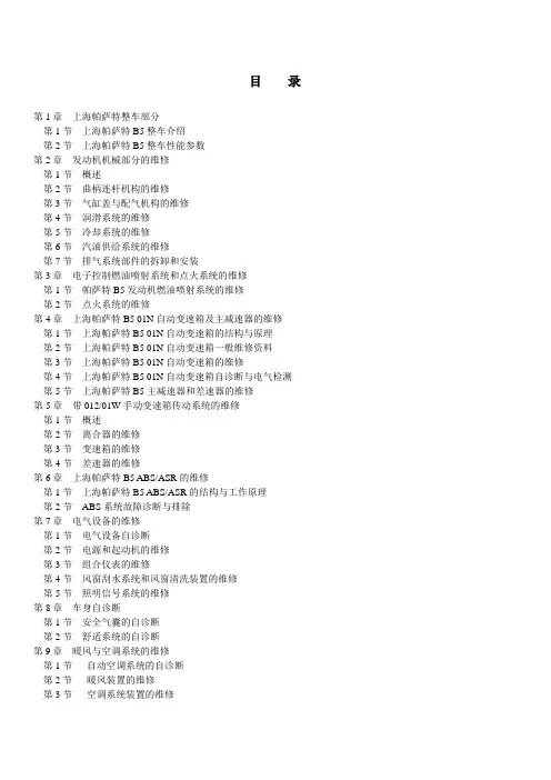
目录第1章上海帕萨特整车部分第1节上海帕萨特B5整车介绍第2节上海帕萨特B5整车性能参数第2章发动机机械部分的维修第1节概述第2节曲柄连杆机构的维修第3节气缸盖与配气机构的维修第4节润滑系统的维修第5节冷却系统的维修第6节汽油供给系统的维修第7节排气系统部件的拆卸和安装第3章电子控制燃油喷射系统和点火系统的维修第1节帕萨特B5发动机燃油喷射系统的维修第2节点火系统的维修第4章上海帕萨特B5 01N自动变速箱及主减速器的维修第1节上海帕萨特B5 01N自动变速箱的结构与原理第2节上海帕萨特B5 01N自动变速箱一般维修资料第3节上海帕萨特B5 01N自动变速箱的维修第4节上海帕萨特B5 01N自动变速箱自诊断与电气检测第5节上海帕萨特B5主减速器和差速器的维修第5章带012/01W手动变速箱传动系统的维修第1节概述第2节离合器的维修第3节变速箱的维修第4节差速器的维修第6章上海帕萨特B5 ABS/ASR的维修第1节上海帕萨特B5 ABS/ASR的结构与工作原理第2节ABS系统故障诊断与排除第7章电气设备的维修第1节电气设备自诊断第2节电源和起动机的维修第3节组合仪表的维修第4节风窗刮水系统和风窗清洗装置的维修第5节照明信号系统的维修第8章车身自诊断第1节安全气囊的自诊断第2节舒适系统的自诊断第9章暖风与空调系统的维修第1节自动空调系统的自诊断第2节暖风装置的维修第3节空调系统装置的维修第10章上海帕萨特B5轿车全车电路图第1节基本电路图第2节5V发动机电路图第3节ABS防抱死制动系统电路图第4节自动变速器电气系统电路图第5节安全气囊系统电路图第6节舒适系统电路图第7节空调系统电路图第8节收放机电路图附录中央电器板与保险丝架等上海大众-帕萨特B5帕萨特B5>>全车电路(/jingpin/qigou/passat/22cszc/23qcdl/qcdlt.htm)全车电路图一、基本电路图二、5V发动机电路图三、ABS防抱死制动系统电路图四、安全气囊系统电路图五、舒适电子系统电路图六、空调系统电路图七、收放机电路图八、附录一、基本电路图1、蓄电池、点火开关、发电机、起动机、X触点继电器电路图(1-14)见图22-1。
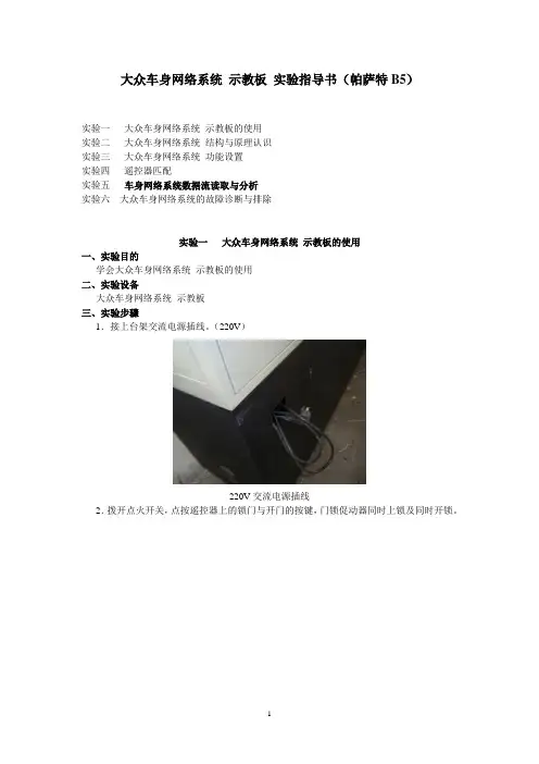
大众车身网络系统示教板实验指导书(帕萨特B5)实验一大众车身网络系统示教板的使用实验二大众车身网络系统结构与原理认识实验三大众车身网络系统功能设置实验四遥控器匹配实验五车身网络系统数据流读取与分析实验六大众车身网络系统的故障诊断与排除实验一大众车身网络系统示教板的使用一、实验目的学会大众车身网络系统示教板的使用二、实验设备大众车身网络系统示教板三、实验步骤1.接上台架交流电源插线。
(220V)220V交流电源插线2.拨开点火开关,点按遥控器上的锁门与开门的按键,门锁促动器同时上锁及同时开锁。
与点火开关一体的遥控器从上到下按键:1-锁门;2-开尾门;3-开锁门锁促动器3.长按遥控器上的锁门与开门的按键,左前车窗电机上升及下降。
4.插入点火开关点火开关5.操作车窗主开关,各车窗按控制方向动作。
车窗主开关1-手控开锁开关;2-手控上锁开关;3-左前车窗控制开关;4-右前车窗控制开关;5-锁定其他车窗控制开关;6-左后车窗控制开关;7-右后车窗控制开关;6.操作门锁控制开关,各车窗门锁马达按相应方向动作。
7.按下锁定开关,左后/右前/右后车窗电机不动作。
8.操作单独的控制开关,对应的独立车窗电机动作。
单独的车窗控制开关(左后/右前/右后)9.操作后视镜开关,后视镜按控制方向动作。
四、思考题1.帕萨特汽车左后电动车窗如何控制?2.帕萨特汽车后视镜如何控制?实验二大众车身网络系统结构与原理认识一、实验目的大众车身网络系统结构与原理认识二、实验设备大众车身网络系统示教板三、实验步骤1.打开点火开关,操作各控制开关。
中控锁、后视镜、电动车窗进入工作状态。
2.系统元件认识1)遥控器2)舒适电脑3)车窗电机(控制单元)4)仪表5)车窗主控制开关车窗主开关1-手控开锁开关;2-手控上锁开关;3-左前车窗控制开关;4-右前车窗控制开关;5-锁定其他车窗控制开关;6-左后车窗控制开关;7-右后车窗控制开关;6)后视镜控制开关7)后视镜8)尾门促动器9)油箱开启电机10)OBD 诊断座11)电动车窗传动机构12)电动车窗结构13)车身网络系统各车窗电机/后视镜控制信号通过CAN-BUS传送3.Can-Bus总线技术是通过车身各个部位的传感器,汽车的各种行驶数据会被发送到“总线”上,这些数据没有指定的接收者,凡是需要这些数据的接收端都可以从“总线”上读取需要的信息。
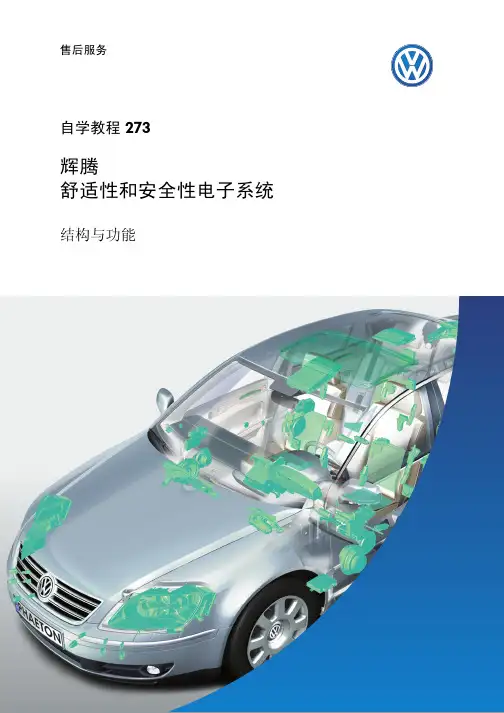
“收到请求!”请上车!“你好,天线:“明白,已开请开门!”锁!”2概览简介进入和起动授权舒适/便利功能系统中央控制单元天窗电子装置多功能方向盘音响系统座椅驻车辅助. . . . . . . . . . . . . . . . . . . . . . . . . . . . . . . . . . . . . . . .知识测验. . . . . . . . . . . . . . . . . . . . . . . . . . . . . . . . . . . . . . . .34简介-最新的刮水器系统,带有两个独立的电子控制电机机组--新型定向照明,可以保证黑夜里安全上下车-车速调节的导流板本自学教程向您展示了辉腾上整个舒适性和安全性电子系统的概况。
它向您提供的信息有:5-音响系统,专门按照车辆内部空间定制-最新的进入和起动授权系统,无需使用钥匙-全方位可调式座椅,带有记忆、空调和按摩6简介舒适性和安全性电子系统一览部件电路图中的名称自诊断地址编号其它信息车载电网控制单元J 51909自学教程272天窗电子装置控制单元J 52838自学教程 273组合仪表中的网关J 533/J 28519/17自学教程 273尾门控制单元J 605通过46 自学教程 273舒适/便利功能系统中央控制单元J 39346自学教程 273进入和起动授权控制单元J 51805自学教程 273 Climatronic 自动空调控制单元J 25508自学教程 271转向柱电子装置控制单元J 52716自学教程 273驻车辅助控制单元J 44676自学教程 273轮胎压力监控控制单元J 50265自学教程 270驾驶员带记忆的座椅调节控制单元J 13636自学教程 273副驾驶员带记忆的座椅调节控制单元J 52106自学教程 273后部带记忆的座椅调节控制单元J 52266自学教程 273车门控制单元,驾驶员侧J 386通过46 自学教程 273车门控制单元,副驾驶员侧J 387通过46 自学教程 273车门控制单元,左后J 388通过46 自学教程 273车门控制单元,右后J 389通过46 自学教程 273刮水器控制单元(主)J 40068自学教程 273副驾驶员侧车窗玻璃刮水器马达控制单元(从)J 584通过68 自学教程 273前部信息显示和操作单元控制单元J 52307自学教程 274后部信息显示和操作单元控制单元J 52427自学教程 27478进入和起动授权旁边这张图片为您提供了进入和起动授权系统各部件的一览图。