TL245中文版(内部翻译)
- 格式:pdf
- 大小:127.36 KB
- 文档页数:7
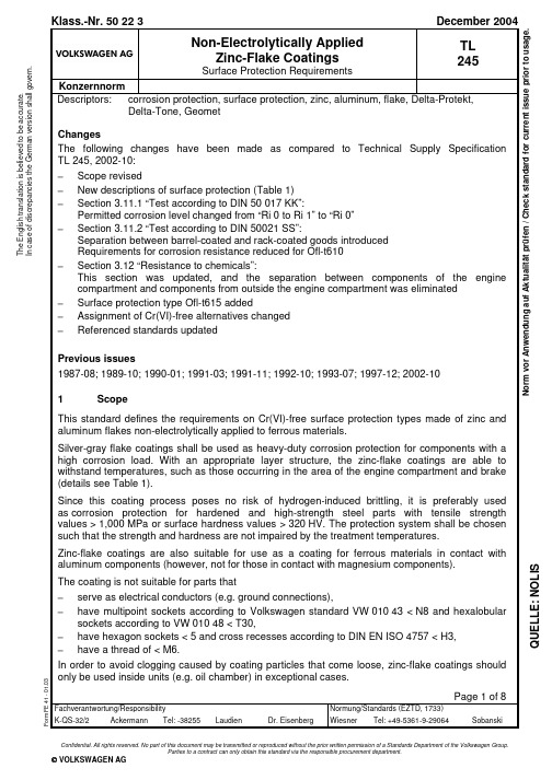
Confidential. All rights reserved. No part of this document may be transmitted or reproduced without the prior written permission of a Standards Department of the Volkswagen Group.Parties to a contract can only obtain this standard via the responsible procurement department.© VOLKSWAGEN AGT h e E n g l i s h t r a n s l a t i o n i s b e l i e v e d t o b e a c c u r a t e . I n c a s e o f d i s c r e p a n c i e s t h e G e r m a n v e r s i o n s h a l l g o v e r n .Q U E L L E : N O L I SPage 2TL 245: 2004-122 DesignationSee VW 137 50, Section 2.3 Requirements3.1 Surface protection typesThe surface protection types listed in Table 1 apply; for replacement of surface protection types that are no longer permitted, see Table 2. Examples of systems that were previously released part-specifically are listed in Appendix A.1.Table 1Characteristics and appearanceSurface protectiontypeOfl-t602 Basic coating with topcoat (inorganic), without lubricant additive.Zinc-flake coating, Cr(VI)-free, silver-gray; use in exposed installationpositions, e.g. in the engine compartment and chassis areas.– Burn-in temperature up to max. +300 °C,– Endurance service temperature max. +180 °C (short-term temperaturepeaks up to +300 °C).Ofl-t610 Basic coating without topcoat, without lubricant additive.Zinc-flake coating, Cr(VI)-free, silver-gray; corrosion protection preferablyfor components that are to be painted (body construction). Standardsurface protection for threaded parts with microencapsulation.– Burn-in temperature up to max. +200 °C,– Reduced corrosion resistance (see Section 3.11),– Reduced endurance service temperature without additional coatings(+125 °C).Ofl-t611 As for Ofl-t602, but with lower burn-in temperature. Consequently, suitablefor components that cannot be exposed to high temperatures, e.g. springelements, low-temperature formed and hardened sheets or high-strengthsteel parts.– Burn-in temperature max. +230 °C,– Endurance service temperature max. +200 °C (short-term temperaturepeaks up to +300 °C).Ofl-t615 As for Ofl-t610, but additionally lubricant (greenish) according toTL 521 65. Standard surface protection for self-locking nuts with plasticlocking element.– Burn-in temperature up to max. +200 °C,– Reduced corrosion resistance (see Section 3.11),– Reduced endurance service temperature without additional coatings(+125 °C).Ofl-t647 Basic coating with topcoat (inorganic), with lubricant additive.Zinc-flake coating, Cr(VI)-free, silver-gray, standard surface protection forthreaded parts with metric ISO standard threads (see VW 011 10)– Burn-in temperature up to max. +300 °C,– Endurance service temperature max. +180 °C (short-term temperaturepeaks up to +300 °C).Page 3TL 245: 2004-12Table 2Protection type designated for new designs Impermissible surface protection type fornew designsComponents of a general natureOfl-t300Ofl-t610Ofl-t310 Ofl-t610Ofl-t320 Ofl-t611Ofl-t600 Ofl-t602 1)Ofl-t620 Ofl-t602 1)Threaded parts with metric ISO standard threadsOfl-t300Ofl-t647 2)Ofl-t310 Ofl-t647 2)Ofl-t320 Ofl-t647 3)Ofl-t345 Ofl-t647 3)Ofl-t600 Ofl-t647 2)Ofl-t620 Ofl-t647 3)Ofl-t645 Ofl-t647 3)1) Ofl-t611, if operating temperatures of up to 200 °C and/or if lower burn-in temperatures up to max. 230 °C are required2) Ofl-t610, if component is installed in the body construction before painting or for threaded parts with microencapsulation3) Ofl-t615, if self-locking nut with plastic locking element3.2 General requirementsApproval of first supply and changes according to VW 011 55.Avoidance of hazardous substances according to VW 911 01.10 finished parts are required for complete testing. For first-sample release of small parts,e.g., threaded fastening elements, a test production of > 50 kg shall be performed.The coating materials must not contain any Cr(VI) compounds in order to ensure that the resultant coatings are likewise Cr(VI)-free.Unless certain sections of a part that are marked in the drawing are excluded from the surface coating, the entire surface of the parts must comply with the required surface protection type and display the prescribed properties. There shall be firm adhesion between coatings and base material (see Section 3.10); there shall be no flaking of the coating or cracks under elastic deformation. The protective coatings must not exhibit any pores, cracks, damage, or other flaws that impair the corrosion protection and/or function.The production process and its control shall not impair the functional characteristics of the finished part. Thus for example, the coating must not flake or crack when the springs or spring washers are mounted or used as intended.With proper mounting, the coating shall not be damaged in a way that would result in impairment of function and/or decrease in the specified corrosion protection.Page 4TL 245: 2004-12The selection of supplier and coating system is subject to agreement with the VW Group Central Laboratory (K-QS-32) and/or the AUDI Group Test Laboratories (I/GQ-32 and N/GQ-55) prior to usage of the given part.3.3 Threaded parts with metric ISO standard threadsThe coating process shall not impair the mechanical and physical properties specified for joining elements. Therefore, the manufacturer has to check whether the baking conditions specified by the coating company are suitable for the parts to be coated.An essential functional property of threaded parts with metric ISO standard threads is their compliance with specified coefficients of friction. In order to ensure that the coefficients of friction comply with VW 011 29, a topcoat with integrated lubricant additive is prescribed for surface protection type Ofl-t647, in addition to the base flake coating.In the case of screws and bolts, the test requirements listed below only apply to the head and/or the wrench bearing surfaces, in the case of nuts, they apply only to the nut body with the exception of the thread. For threaded and similar shaped parts, such as studs, the test requirements only apply to the face surfaces.Reduced requirements (see Sections 3.9 and 3.11.2) apply to process- or geometry-related weak spots of coating areas on joining elements and quick fastening elements.Prior to coating, threaded parts shall exhibit tolerances corresponding to the coating thickness. Metric threaded parts shall preferably be designed according to VW 116 24 (internal threads) or VW 116 27 (external threads). After the coating process, the zero line must not be exceeded in the case of external threads, and it must not be fallen below in the case of internal threads.For further information see VW 011 10, Section 2.3.4 Base coatingRepeated treatment would be useful to produce an even and opaque coating. It is compulsory for barrel coating.The coating system’s corrosion protection performance is enhanced by repeated coating. Type and number of the coating processes for flake coating should be specified in the drawing if this is important for the quality of the basic layer in addition to the specified layer thickness.3.5 Topcoats/lubricant additivesIn order to observe the anti-corrosion requirements and to guarantee the defined coefficients of friction, additional system-specific topcoats, optionally with integrated lubricant additive, may be used. The topcoats must be coordinated to suit the base coating. They must not cause any functional impairment.If, in addition to corrosion protection, further functional surface characteristics such as paintability, compatibility with other agents, friction properties, threading behavior, vulcanizability or temperature behavior are required, part-specific tests or functional tests must be performed.3.6 Base materialSee drawing.Page 5TL 245: 2004-123.7 PretreatmentPrincipally metallically bright. Alternatively (depending on the coating system) micro-crystalline thin layer phosphating (1 to 3 g/m²) is permissible.Prior to coating, hot alkaline and/or mechanical cleaning (e.g. abrasive blasting) shall be carried out on hardened or high-strength steel parts with a tensile strength > 1,000 MPa. Special treatments that could lead to hydrogen absorption are only possible in individual cases upon provision of verification of the process management in coordination with the responsible QA laboratory of the Volkswagen Group.3.8 Dry filmComposition, see International Material Data System (IMDS).3.9 Dry coating thicknessTesting according to DIN EN ISO 1463, DIN EN ISO 2064 and DIN EN ISO 2178; measuring point position for threaded parts with metric ISO standard thread according to DIN EN ISO 4042. Requirement: minimum coating thickness 8 µm; maximum coating thickness 18 µm. If due to the process or geometry, the minimum coating thickness is not achieved, this is permitted as long as the corrosion protection and functionality, e.g. threading behavior, are not impaired.3.10 AdhesionAdhesive tape with an adhesive strength of (7 ± 1) N per 25 mm width is used for the adhesion test acc. to DIN EN ISO 10683. It is firmly pressed onto the specimen surface and then removed with a jerk-like motion perpendicular to the surface. There must be no large-area removal of the coating. Small particles of the coating that adhere to the tape are permissible.3.11 Corrosion behavior3.11.1 Test according to DIN 50017-KK (only for first-sample test)The scribing line is applied on the basis of DIN EN ISO 7253, component dimensions permitting. After a test duration of 720 h and evaluation according to DIN EN ISO 4628-3, the following minimum requirements must be adhered to at all times:base metal corrosion on surface: Ri 0,base metal corrosion permissible in the scribing line, but no rust creep.Page 6TL 245: 2004-123.11.2 Test according to DIN 50021 SSGeneral requirements (not for Ofl-t610 and barrel-coated goods with thread):no base metal corrosion (Ri 0) after a test duration of 720 h without thermal conditioning,no base metal corrosion (Ri 0) after a test duration of 480 h with thermal conditioning for 96 h at +180 °C (for Ofl-t611: +200 °C).Deviating requirement for Ofl-t610:no base metal corrosion (Ri 0) after a test duration of 480 h without thermal conditioning. Deviating requirements for barrel-coated goods with thread (see also Section 3.3):no base metal corrosion (Ri 0) after a test duration of 600 h without thermal conditioning,no base metal corrosion (Ri 0) after a test duration of 480 h with thermal conditioning for 96 h at +180 °C (for Ofl-t611: +200 °C).3.12 Resistance to chemicals (only for first-sample test)Testing according to VDA1) 621-412 in the following media:FAM test fuel according to VDA 621-412, test A 4.1.1 Y,Diesel fuel according to TL 788 and VDA 621-412, test A 4.1.2 X,Biodiesel (FAME) according to DIN EN 14214 and VDA 621-412, test A 4.1.2 X,Premium unleaded gasoline according to DIN EN 228 and test according to VDA 621-412, test A 4.1.3 Y,Factory-fill engine oil according to TL 521 73 (Burmah Castrol Oil code A97075PBC) and VDA 621-412, test A 4.1.4 X,Hydraulic fluid according to TL 521 46 and VDA 621-412, test A 4.1.6 X,Automatic transmission fluid according to TL 521 62 and VDA 621-412, test A 4.1.7 X,Coolant according to TL 774 and VDA 621-412, test A 4.2.2 X.A surface change is not permitted (max. characteristic value 1 according to DIN EN ISO 4628-1). Additionally, tests are performed in the following medium:Brake fluid according to TL 766 and VDA 621-412, test A 4.2.1 X.The following requirement applies to this medium: swellings that have returned to normal after 24 h are permitted.For small parts, test B must be used instead of test A. Small parts can be submersed completely and compared with a new part from the same manufacturing batch.4 Referenced standards2)TL 766 Brake Fluid; Material RequirementsTL 774 Ethylene Glycol-Based Coolant Additive; Material RequirementsTL 788 Dieselkraftstoff, Kraftstoffanforderungen (currently only available in German) TL 521 46 Central Hydraulic System Fluid; Lubricant RequirementsTL 521 62 Factory-Fill-for-Life Automatic Transmission Fluid; Lubricant Requirements TL 521 65 Lubricant (Greenish) for Threaded Fasteners; Material RequirementsTL 521 73 Factory Fill Engine Oil SAE 0W-30 with Fuel-Saving Properties for Extended Oil Change Intervals; Requirement, Testing1)VDA = German Association of the Automotive Industry2)In this section, terminological inconsistencies may occur as the original titles are used.Page 7TL 245: 2004-12VW 010 43 Multipoint Socket Profile; Drive Shape for Threaded PartsVW 010 48 Round Hexagon Socket; Drive Shape for Threaded PartsVW 011 10 Threaded Joints; Design, Assembly and Process AssuranceVW 011 29 Limit Values for Coefficients of Friction; Mechanical Joining Elements with Metric ISO ThreadVW 011 55 Vehicle Supply Parts; Approval of First Supply and ChangesVW 116 24 Metric ISO Thread; Limit Dimensions for Tolerance Class 6f/6GVW 116 27 Thread Limit Dimensions for External Threads of Tolerance Class 6e; Metric ISO ThreadsVW 137 50 Surface Protection of Metal Parts; Degrees of Protection, Codes, RequirementsVW 911 01 Environmental Standard for Vehicles; Vehicle Parts, Materials, Operating Fluids; Avoidance of Hazardous SubstancesVDA 621-412 Anstrichtechnische Prüfungen; Chemikalienbeständigkeit von Kraftfahrzeug-Lackierungen (Tests for Coating Methods; Resistance toChemicals of Motor Vehicle Paints; only available in German)DIN 50017 Atmospheres and their Technical Application; Condensation Water Test AtmospheresDIN 50021 Spray Tests with Different Sodium Chloride SolutionsDIN EN 228 Automotive Fuels – Unleaded Petrol – Requirements and Test Methods DIN EN 14214 Automotive Fuels – Fatty Acid Methyl Esters (FAME) for Diesel Engines – Requirements and Test MethodsDIN EN ISO 1463 Metallic and Oxide Coatings – Measurement of Coating Thickness – Microscopical MethodDIN EN ISO 2064 Metallic and Other Non-Organic Coatings – Definitions and Conventions Concerning the Measurement of ThicknessDIN EN ISO 2178 Non-Magnetic Coatings on Magnetic Substrates – Measurement of Coating Thickness – Magnetic MethodDIN EN ISO 4042 Fasteners – Electroplated CoatingsDIN EN ISO 4628-1 Paints and Varnishes – Evaluation of Degradation of Coatings – Designation of Quantity and Size of Defects, and of Intensity of UniformChanges in Appearance – Part 1: General Introduction and DesignationSystemDIN EN ISO 4628-3 Paints and Varnishes – Evaluation of Degradation of Coatings – Designation of Quantity and Size of Defects, and of Intensity of UniformChanges in Appearance – Part 3: Assessment of Degree of RustingDIN EN ISO 4757 Cross Recesses for ScrewsDIN EN ISO 7253 Paints and Varnishes – Determination of Resistance to Neutral Salt Spray (Fog)DIN EN ISO 10683 Fasteners – Non-Electrolytically Applied Zinc Flake CoatingsPage 8TL 245: 2004-12Appendix A (informative)A.1 Released surface protection systemsA.1.1 Ofl-t602Any system, e.g.:DELTA-PROTEKT® KL100 + DELTA-PROTEKT® VH300 GEOMET 321 PLUS 10A.1.2 Ofl-t610DELTA-TONE® 9000A.1.3 Ofl-t611DELTA-PROTEKT®KL100 + DELTA-PROTEKT®VH300A.1.4 Ofl-t615DELTA-TONE® 9000 + lubricant (greenish) according to TL 521 65 A.1.5 Ofl-t647Any system.However, for joining elements only:DELTA-PROTEKT® KL100 + DELTA-PROTEKT®VH301GZ GEOMET 321 PLUS VL。
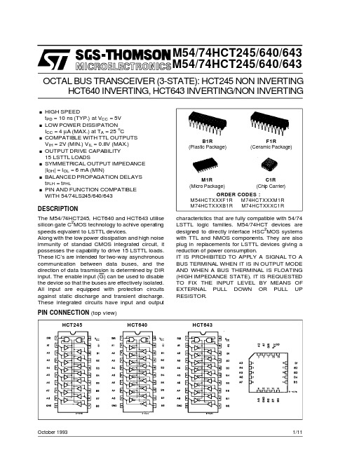
M54/74HCT245/640/643M54/74HCT245/640/643October 1993HCT640INVERTING,HCT643INVERTING/NON INVERTINGOCTAL BUS TRANSCEIVER (3-STATE):HCT245NON INVERTINGB1R(Plastic Package)ORDER CODES :M54HCTXXXF1R M74HCTXXXM1R M74HCTXXXB1R M74HCTXXXC1RF1R(Ceramic Package)M1R(Micro Package)C1R (Chip Carrier)PIN CONNECTION (top view).HIGH SPEEDt PD =10ns (TYP.)at V CC =5V .LOW POWER DISSIPATIONI CC =4µA (MAX.)at T A =25oC.COMPATIBLE WITH TTL OUTPUTS V IH =2V (MIN.)V IL =0.8V (MAX.).OUTPUT DRIVE CAPABILITY 15LSTTL LOADS.SYMMETRICAL OUTPUT IMPEDANCE |I OH |=I OL =6mA (MIN).BALANCED PROPAGATION DELAYS t PLH =t PHL.PIN AND FUNCTION COMPATIBLE WITH 54/74LS245/640/643DESCRIPTIONThe M54/74HCT245,HCT640and HCT643utilise silicon gate C 2MOS technology to achive operating speeds eqivalent to LSTTL devices.Along with the low power dissipation and high noise immunity of standad CMOS integrated circuit,it possesses the capability to drive 15LSTTL loads.These IC’s are intended for two-way asynchronous communication between data buses,and the direction of data trasmission is determined by DIR input.The enable input (G)can be used to disable the device so that the buses are effectively isolated.All input are equipped with protection circuits against static discharge and transient discharge.These integrated circuits have input and output characteristics that are fully compatible with 54/74LSTTL logic families.M54/74HCT devices are designed to directly interface HSC 2MOS systems with TTL and NMOS components.They are also plug in replacements for LSTTL devices giving a reduction of power consumption.IT IS PROHIBITED TO APPLY A SIGNAL TO A BUS TERMINAL WHEN IT IS IN OUTPUT MODE AND WHEN A BUS THERMINAL IS FLOATING (HIGH IMPEDANCE STATE),IT IS REQUESTED TO FIX THE INPUT LEVEL BY MEANS OF EXTERNAL PULL DOWN OR PULL UP RESISTOR.HCT245HCT640HCT6431/11INPUT AND OUTPUT EQUIVALENT CIRCUITPIN DESCRIPTIONPIN No SYMBOL NAME AND FUNCTION 1DIR Directional Control 2,3,4,5,6,7,8,9A1to A8Data Inputs/Outputs 18,17,16,15,14,13,12,11B1to B8Data Inputs/Outputs19G Output Enabel Input (Active LOW)10GND Ground (0V)20V CCPositive Supply VoltageIEC LOGIC SYMBOLSTRUTH TABLEINPUT FUNCTIONOUTPUT G DIR A BUS B BUS HCT245HCT640HCT643L L OUTPUT INPUT A =B A =B A =B L H INPUT OUTPUTB =A B =A B =A HXZZZZZX:”H”or ”L”Z:High impeda nceHCT245HCT640HCT643M54/M74HCT245/640/6432/11M54/M74HCT245/640/643 LOGIC DIAGRAM(HCT640)NOTE:IN CASE OF HCT245OR HCT643,INPUT INVERTERS MARKED*AT A BUS AND B BUS ARE ELIMINATED RESPECTIVELYABSOLUTE MAXIMUM RATINGSSymbol Parameter Value Unit V CC Supply Voltage-0.5to+7V V I DC Input Voltage-0.5to V CC+0.5V V O DC Output Voltage-0.5to V CC+0.5VI IK DC Input Diode Current±20mAI OK DC Output Diode Current±20mAI O DC Output Source Sink Current Per Output Pin±35mAI CC or I GND DC V CC or Ground Current±70mAP D Power Dissipation500(*)mW T stg Storage Temperature-65to+150o C T L Lead Temperature(10sec)300o C Absolute Maximum Ratings are those values beyond whichdamage to the device may occu r.Functiona l ope ration und er these cond ition isnotimplied. (*)500mW:≅65o C derate to300mW by10mW/o C:65o C to85o C3/11RECOMMENDED OPERATING CONDITIONSSymbol Parameter Value Unit V CC Supply Voltage 4.5to5.5V V I Input Voltage0to V CC V V O Output Voltage0to V CC VT op Operating Temperature:M54HC SeriesM74HC Series -55to+125-40to+85o Co Ct r,t f Input Rise and Fall Time(V CC=4.5to5.5V)0to500ns DC SPECIFICATIONSSymbol ParameterTest Conditions ValueUnit V CC(V)T A=25o C54HC and74HC-40to85o C74HC-55to125o C54HCMin.Typ.Max.Min.Max.Min.Max.V IH High Level InputVoltage 4.5to5.52.0 2.0 2.0VV IL Low Level InputVoltage 4.5to5.50.80.80.8VV OH High LevelOutput Voltage4.5V I=V IHorV ILI O=-20µA 4.4 4.5 4.4 4.4VI O=-6.0mA 4.18 4.31 4.13 4.10V OL Low Level OutputVoltage4.5V I=V IHorV ILI O=20µA0.00.10.10.1VI O=6.0mA0.170.260.330.4I I Input LeakageCurrent 5.5V I=V CC or GND±0.1±1±1µAI OZ3State OutputOff State Current5.5V I=V CC or GND±0.5±5.0±10µAI CC Quiescent SupplyCurrent5.5V I=V CC or GND44080µA∆I CC Additional worstcase supplycurrent 5.5Per Input pinV I=0.5V orV I=2.4VOther Inputs atV CC or GNDI O=02.0 2.93.0mAM54/M74HCT245/640/643 4/11AC ELECTRICAL CHARACTERISTICS(C L=50pF,Input t r=t f=6ns)Symbol ParameterTest Conditions ValueUnit V CC(V)C L(pF)T A=25o C54HC and74HC-40to85o C74HC-55to125o C54HCMin.Typ.Max.Min.Max.Min.Max.t TLH t THL Output TransitionTime4.5507121518nst PLH t PHL PropagationDelay Time4.55013222833ns4.515018303845nst PZL t PZH Output EnableTime4.550R L=1KΩ19303845ns4.5150R L=1KΩ24384857nst PLZ t PHZ Output DisableTime4.550R L=1KΩ17303845nsC IN Input Capacitance DIR,G5101010pFC I/OUT OutputCapacitance An,Bn13pFC PD(*)Power DissipationCapacitanceHCT245HCT640/6434139pF(*)C PD is defined as the value of the IC’s internal equivalent capac itanc e which is calculated from the operating current con sump tion without load. (Refer to Test Circuit).Average operting current can be obtained by the following equ ation.I CC(opr)=C PD•V CC•f IN+I CC/8(per circuit) SWITCHING CHARACTERISTICS TEST WAVEFORMM54/M74HCT245/640/6435/11TEST CIRCUIT I CC(Opr.)C PD CALCULATIONC PD is to be calculated with the followingformula by using the measured value of I CC(Opr.)in the test circuit opposite.C PD=I CC(Opr.)f IN x V CCIn determining the value of C PD,a relativelyhigh frequency of1MHz was applied to f IN,inorther to eliminate any error caused by thequiescent supply current.M54/M74HCT245/640/6436/11M54/M74HCT245/640/643 Plastic DIP20(0.25)MECHANICAL DATAmm inchDIM.MIN.TYP.MAX.MIN.TYP.MAX.a10.2540.010B 1.39 1.650.0550.065b0.450.018b10.250.010D25.4 1.000E8.50.335e 2.540.100e322.860.900F7.10.280I 3.930.155L 3.30.130Z 1.340.053P001J7/11M54/M74HCT245/640/643Ceramic DIP20MECHANICAL DATAmm inch DIM.MIN.TYP.MAX.MIN.TYP.MAX.A250.984 B7.80.307D 3.30.130E0.5 1.780.0200.070 e322.860.900F 2.29 2.790.0900.110G0.40.550.0160.022I 1.27 1.520.0500.060L0.220.310.0090.012 M0.51 1.270.0200.050 N14°(min.),15°(max.)P7.98.130.3110.320 Q 5.710.225P057H 8/11M54/M74HCT245/640/643SO20MECHANICAL DATAmm inchDIM.MIN.TYP.MAX.MIN.TYP.MAX.A 2.650.104a10.100.200.0040.007a2 2.450.096b0.350.490.0130.019b10.230.320.0090.012C0.500.020c145°(typ.)D12.6013.000.4960.512E10.0010.650.3930.419e 1.270.050e311.430.450F7.407.600.2910.299L0.50 1.270.190.050M0.750.029S8°(max.)P013L9/11M54/M74HCT245/640/643PLCC20MECHANICAL DATAmm inch DIM.MIN.TYP.MAX.MIN.TYP.MAX.A9.7810.030.3850.395 B8.899.040.3500.356D 4.2 4.570.1650.180d1 2.540.100d20.560.022E7.378.380.2900.330e 1.270.050e3 5.080.200F0.380.015G0.1010.004 M 1.270.050M1 1.140.045P027A 10/11元器件交易网M54/M74HCT245/640/643 Information furnished is believed to be accurate and reliable.However,SGS-THOMSON Microelectronics assumes no responsability for theconsequences of use of such information nor for any infringement of patents or other rights of third parties which may results from its use.Nolicense is granted by implication or otherwise under any patent or patent rights of SGS-THOMSON Microelectronics.Specificationsmentionedin this publication are subject to change without notice.This publication supersedes and replaces all information previously supplied.SGS-THOMSON Microelectronics products are not authorized for use ascritical components in life support devices or systems without expresswritten approval of SGS-THOMSON Microelectonics.©1994SGS-THOMSON Microelectronics-All Rights ReservedSGS-THOMSON Microelectronics GROUP OF COMPANIESAustralia-Brazil-France-Germany-Hong Kong-Italy-Japan-Korea-Malaysia-Malta-Morocco-The Netherlands-Singapore-Spain-Sweden-Switzerland-Taiwan-Thailand-United Kingdom-U.S.A11/11。
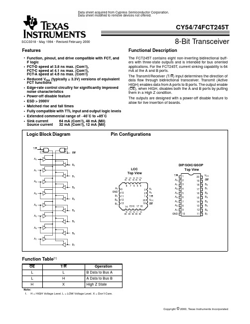
8-Bit TransceiverCY54/74FCT245TSCCS018 - May 1994 - Revised February 2000Data sheet acquired from Cypress Semiconductor Corporation.Data sheet modified to remove devices not offered.Copyright © 2000, T exas Instruments IncorporatedFeatures•Function, pinout, and drive compatible with FCT, and F logic•FCT-D speed at 3.8 ns max. (Com’l),FCT-C speed at 4.1 ns max. (Com’l),FCT-A speed at 4.6 ns max. (Com’l)•Reduced V OH (typically = 3.3V) versions of equivalent FCT functions•Edge-rate control circuitry for significantly improved noise characteristics •Power-off disable feature •ESD > 2000V•Matched rise and fall times•Fully compatible with TTL input and output logic levels •Extended commercial range of −40˚C to +85˚C •Sink current 64 mA (Com’l), 48 mA (Mil)Source current 32 mA (Com’l), 12 mA (Mil)Functional DescriptionThe FCT245T contains eight non-inverting bidirectional buff-ers with three-state outputs and is intended for bus oriented applications.For the FCT245T,current sinking capability is 64mA at the A and B ports.The Transmit/Receiver (T/R)input determines the direction of data flow through bidirectional transceiver.Transmit (Active HIGH)enables data from A ports to B ports.The output enable (OE),when HIGH,disables both the A and B ports by putting them in a High Z condition.The outputs are designed with a power-off disable feature to allow for live insertion of boards.Function Table [1]OE T/R Operation L L B Data to Bus A L H A Data to Bus B HXHigh Z StateNote:1.H = HIGH Voltage Level. L = LOW Voltage Level. X = Don’t Care.Logic Block DiagramPin ConfigurationsA 0A 1A 2A 3A 4A 5A 6A 7OEB 0B 1B 2B 3B 4B 5B 6B 7T/R4891011127651516171832120131419A 6A 5A 3B 1B 4B 0B 7V CC GND B 3Top ViewA 2LCCT/R A 0A 1A 7B 5B 612345678910111216171819201314V CC 15Top ViewB 2A 4OEA 0A 1A 2A 3A 4A 5A 6A 7OEB 0B 1B 2B 3B 4B 5B 6B 7T/R GNDDIP/SOIC/QSOPMaximum Ratings[2,3](Above which the useful life may be impaired.For user guidelines, not tested.)Storage T emperature.....................................−65°C to +150°C Ambient T emperature withPower Applied..................................................−65°C to +135°C Supply Voltage to Ground Potential..................−0.5V to +7.0V DC Input Voltage.................................................−0.5V to +7.0V DC Output Voltage..............................................−0.5V to +7.0V DC Output Current (Maximum Sink Current/Pin).......120 mA Power Dissipation..........................................................0.5W Static Discharge Voltage............................................>2001V (per MIL-STD-883, Method 3015)Operating RangeRange RangeAmbientTemperature V CC Commercial DT0°C to +70°C5V± 5% Commercial T, AT, CT−40°C to +85°C5V± 5% Military[4]All−55°C to +125°C5V± 10%Electrical Characteristics Over the Operating RangeParameter Description Test Conditions Min.Typ.[5]Max.Unit V OH Output HIGH Voltage V CC=Min., I OH=−32 mA Com’l 2.0VV CC=Min., I OH=−15 mA Com’l 2.4 3.3VV CC=Min., I OH=−12 mA Mil 2.4 3.3V V OL Output LOW Voltage V CC=Min., I OL=64 mA Com’l0.30.55VV CC=Min., I OL=48mA Mil0.30.55V V IH Input HIGH Voltage 2.0V V IL Input LOW Voltage0.8V V H Hysteresis[6]All inputs0.2V V IK Input Clamp Diode Voltage V CC=Min., I IN=−18 mA−0.7−1.2V I I Input HIGH Current V CC=Max., V IN=V CC5µA I IH Input HIGH Current V CC=Max., V IN=2.7V±1µA I IL Input LOW Current V CC=Max., V IN=0.5V±1µA I OS Output Short Circuit Current[7]V CC=Max., V OUT=0.0V−60−120−225mA I OFF Power-Off Disable V CC=0V, V OUT=4.5V±1µACapacitance[6]Parameter Description Typ.[5]Max.UnitC IN Input Capacitance510pFC OUT Output Capacitance912pF Notes:2.Unless otherwise noted, these limits are over the operating free-air temperature range.3.Unused inputs must always be connected to an appropriate logic voltage level, preferably either V CC or ground.4.T A is the “instant on” case temperature.5.Typical values are at V CC=5.0V, T A=+25˚C ambient.6.This parameter is specified but not tested.7.Not more than one output should be shorted at a time.Duration of short should not exceed one second.The use of high-speed test apparatus and/or sampleand hold techniques are preferable in order to minimize internal chip heating and more accurately reflect operational values.Otherwise prolonged shorting ofa high output may raise the chip temperature well above normal and thereby cause invalid readings in other parametric tests.In any sequence of parametertests, I OS tests should be performed last.Power Supply CharacteristicsParameter DescriptionTest ConditionsTyp.[5]Max.Unit I CC Quiescent Power Supply Current V CC =Max., V IN ≤0.2V , V IN ≥V CC −0.2V 0.10.2mA ∆I CC Quiescent Power Supply Current (TTL inputs HIGH)V CC =Max., V IN =3.4V ,[8]f 1=0, Outputs Open0.5 2.0mA I CCDDynamic Power Supply Current [9]V CC =Max., One Input Toggling,50% Duty Cycle, Outputs Open,T/R or OE=GND andV IN ≤0.2V or V IN ≥V CC −0.2V0.060.12mA/MHzI CTotal Power Supply Current [10]V CC =Max.,50%Duty Cycle,Outputs Open,One Bit Toggling at f 1=10 MHz,T/R or OE=GND andV IN ≤0.2V or V IN ≥V CC −0.2V0.7 1.4mAV CC =Max.,50%Duty Cycle,Outputs Open,One Bit Toggling at f 1=10 MHz,T/R or OE=GND and V IN =3.4V or V IN =GND 1.2 3.4mAV CC =Max.,50%Duty Cycle,Outputs Open,Eight Bits Toggling at f 1=2.5 MHz,T/R or OE=GND andV IN ≤0.2V or V IN ≥V CC −0.2V1.32.6[11]mAV CC =Max.,50%Duty Cycle,Outputs Open,Eight Bits Toggling at f 1=2.5 MHz,T/R or OE=GND and V IN =3.4V or V IN =GND3.310.6[11]mANotes:8.Per TTL driven input (V IN =3.4V); all other inputs at V CC or GND.9.This parameter is not directly testable, but is derived for use in Total Power Supply calculations.10.I C=I QUIESCENT + I INPUTS + I DYNAMIC I C =I CC +∆I CC D H N T +I CCD (f 0/2 + f 1N 1)I CC =Quiescent Current with CMOS input levels∆I CC =Power Supply Current for a TTL HIGH input (V IN =3.4V)D H =Duty Cycle for TTL inputs HIGH N T =Number of TTL inputs at D HI CCD =Dynamic Current caused by an input transition pair (HLH or LHL)f 0=Clock frequency for registered devices, otherwise zero f 1=Input signal frequency N 1=Number of inputs changing at f 1All currents are in milliamps and all frequencies are in megahertz.11.Values for these conditions are examples of the I CC formula. These limits are specified but not tested.Document #: 38−00318−BSwitching Characteristics Over the Operating RangeParameter Description FCT245TFCT245ATUnit Fig.No.[13]MilitaryCommercial MilitaryCommercial Min.[12]Max.Min.[12]Max.Min.[12]Max.Min.[12]Max.t PLH t PHL Propagation Delay A to B or B to A 1.57.5 1.57.0 1.5 4.9 1.5 4.6ns 1, 3t PZH t PZL Output Enable Time OE or T/R to A or B 1.510.0 1.59.5 1.5 6.5 1.5 6.2ns 1, 7, 8t PHZ t PLZOutput Disable Time OE or T/R to A or B1.510.01.57.51.56.01.55.0ns1, 7, 8Switching Characteristics Over the Operating Range (continued)Parameter DescriptionFCT245CTFCT245DT Unit Fig.No.[13]MilitaryCommercial Commercial Min.[12]Max.Min.[12]Max.Min.[12]Max.t PLH t PHL Propagation Delay A to B or B to A 1.5 4.5 1.5 4.1 1.5 3.8ns 1, 3t PZH t PZL Output Enable Time OE or T/R to A or B 1.5 6.2 1.5 5.8 1.5 5.0ns 1, 7, 8t PHZ t PLZOutput Disable Time OE or T/R to A or B1.55.21.54.81.54.3ns1, 7, 8Ordering InformationSpeed (ns)Ordering CodePackage Name Package TypeOperating Range 3.8CY74FCT245DTQCT Q520-Lead (150-Mil) QSOP CommercialCY74FCT245DTSOC/SOCT S520-Lead (300-Mil) Molded SOIC 4.1CY74FCT245CTQCT Q520-Lead (150-Mil) QSOP Commercial CY74FCT245CTSOC/SOCT S520-Lead (300-Mil) Molded SOIC 4.5CY54FCT245CTDMB D620-Lead (300-Mil) CerDIP Military CY54FCT245CTLMB L6120-Square Leadless Chip Carrier 4.6CY74FCT245ATPC P520-Lead (300-Mil) Molded DIP Commercial CY74FCT245ATQCT Q520-Lead (150-Mil) QSOP CY74FCT245ATSOC/SOCTS520-Lead (300-Mil) Molded SOIC 4.9CY54FCT245ATDMB D620-Lead (300-Mil) CerDIP Military CY54FCT245ATLMB L6120-Square Leadless Chip Carrier 7.0CY74FCT245TQCT Q520-Lead (150-Mil) QSOP Commercial CY74FCT245TSOC/SOCT S520-Lead (300-Mil) Molded SOIC 7.5CY54FCT245TDMB D620-Lead (300-Mil) CerDIP Military CY54FCT245TLMBL6120-Square Leadless Chip CarrierNotes:12.Minimum limits are specified but not tested on Propagation Delays.13.See “Parameter Measurement Information” in the General Information section.Package Diagrams20-Lead (300-Mil)CerDIP D6MIL −STD −1835D −8 Config.A20-Pin Square Leadless Chip Carrier L61MIL −STD −1835 C −2A20-Lead (300-Mil)Molded DIP P5Package Diagrams (continued)20-Lead Quarter Size Outline Q520-Lead(300-Mil)Molded SOIC S5IMPORTANT NOTICETexas Instruments and its subsidiaries (TI) reserve the right to make changes to their products or to discontinue any product or service without notice, and advise customers to obtain the latest version of relevant information to verify, before placing orders, that information being relied on is current and complete. All products are sold subject to the terms and conditions of sale supplied at the time of order acknowledgement, including those pertaining to warranty, patent infringement, and limitation of liability.TI warrants performance of its semiconductor products to the specifications applicable at the time of sale in accordance with TI’s standard warranty. Testing and other quality control techniques are utilized to the extent TI deems necessary to support this warranty. Specific testing of all parameters of each device is not necessarily performed, except those mandated by government requirements.CERTAIN APPLICATIONS USING SEMICONDUCTOR PRODUCTS MAY INVOLVE POTENTIAL RISKS OF DEATH, PERSONAL INJURY, OR SEVERE PROPERTY OR ENVIRONMENTAL DAMAGE (“CRITICAL APPLICATIONS”). TI SEMICONDUCTOR PRODUCTS ARE NOT DESIGNED, AUTHORIZED, OR WARRANTED TO BE SUITABLE FOR USE IN LIFE-SUPPORT DEVICES OR SYSTEMS OR OTHER CRITICAL APPLICATIONS. INCLUSION OF TI PRODUCTS IN SUCH APPLICATIONS IS UNDERSTOOD TO BE FULLY AT THE CUSTOMER’S RISK.In order to minimize risks associated with the customer’s applications, adequate design and operating safeguards must be provided by the customer to minimize inherent or procedural hazards.TI assumes no liability for applications assistance or customer product design. TI does not warrant or represent that any license, either express or implied, is granted under any patent right, copyright, mask work right, or other intellectual property right of TI covering or relating to any combination, machine, or process in which such semiconductor products or services might be or are used. TI’s publication of information regarding any third party’s products or services does not constitute TI’s approval, warranty or endorsement thereof.Copyright © 2000, Texas Instruments Incorporated。
元器件交易网元器件交易网IMPORTANT NOTICETexas Instruments Incorporated and its subsidiaries (TI) reserve the right to make corrections, modifications,enhancements, improvements, and other changes to its products and services at any time and to discontinueany product or service without notice. Customers should obtain the latest relevant information before placingorders and should verify that such information is current and complete. All products are sold subject to TI’s termsand conditions of sale supplied at the time of order acknowledgment.TI warrants performance of its hardware products to the specifications applicable at the time of sale inaccordance with TI’s standard warranty. T esting and other quality control techniques are used to the extent TIdeems necessary to support this warranty. Except where mandated by government requirements, testing of allparameters of each product is not necessarily performed.TI assumes no liability for applications assistance or customer product design. Customers are responsible fortheir products and applications using TI components. T o minimize the risks associated with customer productsand applications, customers should provide adequate design and operating safeguards.TI does not warrant or represent that any license, either express or implied, is granted under any TI patent right,copyright, mask work right, or other TI intellectual property right relating to any combination, machine, or processin which TI products or services are used. Information published by TI regarding third-party products or servicesdoes not constitute a license from TI to use such products or services or a warranty or endorsement thereof.Use of such information may require a license from a third party under the patents or other intellectual propertyof the third party, or a license from TI under the patents or other intellectual property of TI.Reproduction of information in TI data books or data sheets is permissible only if reproduction is withoutalteration and is accompanied by all associated warranties, conditions, limitations, and notices. Reproductionof this information with alteration is an unfair and deceptive business practice. TI is not responsible or liable forsuch altered documentation.Resale of TI products or services with statements different from or beyond the parameters stated by TI for thatproduct or service voids all express and any implied warranties for the associated TI product or service andis an unfair and deceptive business practice. TI is not responsible or liable for any such statements.Following are URLs where you can obtain information on other Texas Instruments products and applicationsolutions:Products ApplicationsAmplifiers Audio /audioData Converters Automotive /automotiveDSP Broadband /broadbandInterface Digital Control /digitalcontrolLogic Military /militaryPower Mgmt Optical Networking /opticalnetworkMicrocontrollers Security /securityTelephony /telephonyVideo & Imaging /videoWireless /wirelessMailing Address:Texas InstrumentsPost Office Box 655303 Dallas, Texas 75265Copyright 2005, Texas Instruments Incorporated。
Descriptors: corrosion protection, surface protection, zinc, aluminum, flake, DELTA-PROTEKT, DELTA-TONE, Geomet, Magni, Zintek关键词:防腐,表面防护,锌,铝,薄片,Delta-Protekt, Delta-Tone,Geomet,Magni,ZintekPrevious issues 早期版本TL 245: 1987-08, 1989-10, 1990-01, 1991-03, 1991-11, 1992-10, 1993-07, 1997-12, 2002-10, 2004-12, 2007-06Changes 修订The following changes have been made compared with TL 245: 2007-06:相对于2007-06版本的TL 245比较,作了如下修改:– Section 1 "Scope" changed 第1条“适用范围”更新– former Table 2 removed (surface protection types no longer permitted)去除之前的表2(不再允许使用表面防护工艺)– Section 3.3 "Threaded parts with metric ISO thread" changed3.3 “带有米制 ISO-螺纹的螺纹零件”的修订– Note in Section 3.10 "Adhesion" added3.10 “附着力”新增标记– Note in Section 3.11.2 "NSS test as per DIN EN ISO 9227" added3.11.2 “NSS-实验按DIN EN ISO 9227” 新增标记– Section 3.12 "Resistance to chemicals" updated (new Table 2)3.12 “耐化学腐蚀”的更新(新表2)– Referenced standards updated 相关文献的更新– Appendix A updated 附件A的更新1 Scope 适用范围This standard defines the requirements on Cr(VI)-free surface protection types made of zinc flakes and aluminum flakes non-electrolytically applied to ferrous materials.本标准规定了钢铁表面,采用无 Cr(VI)的非电解质锌铝薄片表面防护工艺的技术要求。
74LV245是低压硅栅CMOS器件,与74HC245和74HCT245针脚和功能兼容。
74LV245是八位元收发器,在发送和接收方向上都具有非反相3态总线兼容输出。
发送/接收(DIR)输入控制方向,而输出使能(OE)输入则可实现轻松级联。
针脚OE控制输出,因此总线可以得到有效隔离。
特性和优势
•宽工作电压范围:1.0 V至5.5 V
•最适合低压应用:1.0 V至3.6 V
•接受介于VCC = 2.7 V和VCC = 3.6 V之间的TTL输入电平
•VCC = 3.3 V且T amb = 25 °C时的典型输出地弹:< 0.8 V
•VCC = 3.3 V且T amb = 25 °C时的典型高电平输出电压(VOH)欠冲:> 2 V •ESD保护:
o HBM JESD22-A114E超过2000 V
o MM JESD22-A115-A超过200 V
•多种封装选择
•额定温度范围为-40 °C至+85 °C和-40 °C至+125 °C
外形图
显示功能框图
真值表
INPUTS INPUTS/OUTPUT OE DIR An Bn
H=高电压L=低电压X=无输入、Z=高阻态。
Group standard TL 245Issue 2014-11 Class. No.:50223Descriptors:corrosion protection, surface protection, zinc, aluminum, flake, Delta-Protekt, Delta-Tone, Geomet,Magni, ZintekNon-Electrolytically Applied Zinc Flake CoatingsSurface Protection RequirementsPrevious issuesTL 245: 1987-08, 1989-10, 1990-01, 1991-03, 1991-11, 1992-10, 1993-07, 1997-12, 2002-10, 2004-12, 2007-06, 2011-07, 2011-09, 2013-12ChangesThe following changes have been made to TL 245: 2013-12:–Section A.1.6 "Ofl-t647": "GEOMET® 500 PLUS VLh" added–Applicable documents updatedAlways use the latest version of this standard.Page 1 of 10 This electronically generated standard is authentic and valid without signature.The English translation is believed to be accurate. In case of discrepancies, the German version is alone authoritative and controlling.All rights reserved. No part of this document may be provided to third parties or reproduced without the prior consent of one of the Volkswagen Group’s Standards departments.© Volkswagen Aktiengesellschaft VWNORM-2014-06a-patch5Page 2TL 245: 2014-11ScopeThis standard defines the requirements placed on Cr(VI)-free surface protection types made of zinc flakes and aluminum flakes applied to ferrous materials in a non-electrolytic manner.The silver-gray flake coatings are used as heavy-duty corrosion protection for components with a high corrosion load. With an appropriate layer structure, the zinc flake coatings are able to with‐stand temperatures such as those occurring, e.g., in the engine compartment (for details, see table 1).Since this coating process poses no risk of hydrogen-induced embrittlement, it is preferably used as corrosion protection for hardened and high-strength steel parts with tensile strength values >1 000 MPa or hardness values >320 HV. The protection system must be chosen such that the strength and hardness are not negatively affected by the treatment temperatures.Zinc flake coatings are also suitable for use as a coating for ferrous materials in contact with alumi‐num components (however, not for those in contact with magnesium components).The coating is not suitable for components–that serve as electrical conductors (e.g., ground connections)–inside of engines (e.g., oil chamber) in order to avoid clogging by detached coating particles The coating is only conditionally suitable for components with–triple squares as per Volkswagen standard VW 01043 <N8 and hexalobular sockets as perVW 01048 <T30–hexagon sockets <5 and cross recesses as per DIN EN ISO 4757 <H3–external thread <M6–internal thread <M10–washers with thickness values <1.6 mmDescription See VW 13750, section 2.Requirements Surface protection types The surface protection types listed in table 1 apply. Examples of systems previously released for components are listed in appendix A.1 2 33.1Page 3TL 245: 2014-11Table 13.2General requirementsApproval of first supply and changes as per VW 01155.Avoidance of hazardous substances as per VW 91101.10 finished parts are required for complete testing. For initial sample release of small parts, e.g., threaded fasteners, a test production of >50 kg must be performed.Page 4TL 245: 2014-11The coating materials must not contain any Cr(VI) compounds in order to ensure that the resultant coatings are likewise Cr(VI)-free.Unless certain sections of a part that are marked in the drawing are excluded from the surface coating, the entire surface of the parts must have the required surface protection type with the pre‐scribed properties. The coatings must adhere firmly to the base material (see section 3.10) and the coatings must not chip or crack due to elastic deformation.The protective coatings must not have any pores, cracks, damage, or other flaws that negatively affect the corrosion protection and/or function.The production process and its control must not impair the functional characteristics of the finished part. For example, the coating must not flake or crack when the springs or spring washers are mounted or used as intended.If the coated components are properly mounted, the coating must not be damaged in a way that would negatively affect the function and/or would reduce the specified corrosion protection.The selection of manufacturers and coating systems must be agreed upon with the Volks‐wagen AG Laboratory (GQL-M/1) and/or with the Audi AG test laboratories (I/GQ-31 and/or N/GQ-551) for each individual component before use.Threaded parts with metric ISO threadsThe coating process must not negatively affect the mechanical and physical properties specified for fasteners. Therefore, the manufacturer must check whether the curing conditions specified by the coating company are suitable for the components to be coated.An essential functional property of threaded parts with metric ISO threads is their adherence to specified coefficients of friction. In order to ensure that the coefficients of friction adhere to VW 01129, a top coat with integrated lubricant additive is prescribed for surface protection type Ofl-t647, in addition to the base flake coating. For Ofl-t615, the coefficients of friction as perVW 01129 are ensured by means of additional lubrication as per TL 52165. For the release of new coating systems and the detection of faults in the case of complaints during installation, parts with metric ISO threads must be tested as per VW 01131-1 and VW 01131-2.Metric ISO threads must be designed as per VW 11611. After the coating process, external thread dimensions must not exceed the shaft tolerance zone h in the shaft basis system as per ISO 286and internal thread dimensions must not be below the hole tolerance zone H in the hole basis sys‐tem as per ISO 286.Especially in the case of threaded parts with top coats, it must be ensured that the surfaces are not impermissibly damaged by processes carried out after the coating process, such as 100% part check, packaging, transport, etc. For more information, see the guideline "Berücksichtigung der Schütt- und Transportprozesse bei der Umstellung auf Cr(VI)-freie Oberflächen" ("Consideration of Dumping and Transport Processes During the Changeover to Hexavalent-Chromium-Free Surfa‐ces"), published by Deutscher Schraubenverband e.V. (German Fasteners Association). Rework must always be announced and agreed upon.For further information, see VW 01110-1, section 3.Base coating The base coating contains a binding agent and approx. 70% zinc flakes and approx. 10% alumi‐num flakes. The use of zinc dust is not permissible. In order to reliably achieve coatings that have uniform coverage and that satisfy the test requirements defined in section 3.11.2, a multiple-coat‐ing process is required.3.3 3.4Page 5TL 245: 2014-11Top coat/lubricant additiveIn order to improve corrosion protection and to achieve the defined coefficients of friction, addition‐al system-specific top coats must be used, optionally with an integrated lubricant additive. The top coats must be matched to the base coating. They must not cause any functional impairment.Zinc flake coatings with top coats must not be used if paintability and the bonding of adhesives (al‐so: locking or adhesive coatings for fasteners) are required.Base materialSee drawing or master data list (MDL).PretreatmentUsually bright metal. Alternatively (depending on the coating system), a micro-crystalline, thin-layer phosphate coating (1 g/m 2 to 3 g/m 2) is permissible.Before coating, hot alkaline and/or mechanical cleaning (e.g., abrasive blasting) must be per‐formed on high-strength and hardened steel parts with tensile strength values >1 000 MPa or hard‐ness values >320 HV.Exceptions are only permissible following agreement with the Volkswagen AG Laboratory (GQL-M/1) and/or the Audi AG test laboratories (I/GQ-31 and/or N/GQ-551).Dry filmComposition as per International Material Data System (IMDS).Dry film thickness Testing as per DIN EN ISO 1463, DIN EN ISO 2064, and DIN EN ISO 2178; position of measuring points for threaded parts with metric ISO thread as per DIN EN ISO 4042.The average minimum coat thickness must be 8 µm; the results of the individual measurements may vary within the range from 6 µm to 20 µm. For threaded parts, the specifications only apply to the head and/or to the face surface and wrench bearing surface; for all other surfaces, the mini‐mum coating thickness is achieved if the anti-corrosion requirements are fulfilled.Driving recesses and threaded areas must not have any base coat and/or top coat accumulations that might negatively affect the functional properties.AdhesionA scribing line based on DIN EN ISO 9227 is applied if the component dimensions allow. Adhesive tape with an adhesive strength of (10 ±1) N per 25 mm in width is then used for the adhesion test.The tape is firmly pressed by hand onto the specimen surface and then removed with a sudden motion perpendicular to the surface. Coating must not be removed from a large area. Small parti‐cles of the coating that adhere to the tape are permissible.NOTE 1: Suitable adhesive tape for the test is, e.g., "Tesaband 4657".NOTE 2: In the case of small parts, the adhesion test can be performed without a scribing line.3.5 3.6 3.7 3.8 3.9 3.10Page 6TL 245: 2014-11Corrosion behavior Test atmosphere: Condensation atmosphere with constant humidity (CH) as perDIN EN ISO 6270-2This test is only required for the release of new coating systems. Usually, this test is carried out on coated test panels (for the test scope, see below). Within the framework of an initial sample inspec‐tion, the moisture resistance can also be proven by a certificate issued by the coating material manufacturer.A scribing line based on DIN EN ISO 9227 must be applied. After a test duration of 720 h and eval‐uation as per DIN EN ISO 4628-3, the following requirements must be satisfied in each case as minimum specifications:–Base metal corrosion on surface: Ri 0–Base metal corrosion permissible in the area of the scribing line, but no corrosion creepageNatural salt spray (NSS) test as per DIN EN ISO 9227The following requirements apply to parts in the Receipt of Goods department of the Volkswagen Group plant using the parts (i.e., after packaging and transport).NOTE 3: Usually, the base coat must be applied 3 times in order to safely achieve ≥600 h of re‐sistance to salt spray fog without base metal corrosion.Requirements for components of a general nature–No base metal corrosion (Ri 0) after a test duration of 720 h –No base metal corrosion (Ri 0) after a test duration of 480 h with thermal aging (heat aging/re‐circulated air) 96 h at +180 °CRequirements for threaded barrel plated goods–No base metal corrosion (Ri 0) after a test duration of 600 h without thermal aging –No base metal corrosion (Ri 0) after a test duration of 480 h with thermal aging (heat aging/re‐circulated air) 96 h at +180 °CRequirements for components with surface protection types Ofl-t601, Ofl-t610, andOfl‑t615–No base metal corrosion (Ri 0) after a test duration of 480 h without thermal agingChemical resistance The verification of the resistance to chemicals is only required for the release of new coating sys‐tems. Usually, this test is carried out on coated test panels (for the test scope, see below). As part of the initial sample inspection, resistance to chemicals may also be demonstrated by a certificate issued by the coating material manufacturer.Testing is performed as per DIN EN ISO 2812. The evaluation is performed as perDIN EN ISO 4628-1. For test media and requirements, see table 2.3.113.11.1 3.11.2 3.11.2.1 3.11.2.2 3.11.2.3 3.12Page 7TL 245: 2014-11Table 2Applicable documents4The following documents cited in this standard are necessary to its application.Some of the cited documents are translations from the German original. The translations of Ger‐man terms in such documents may differ from those used in this standard, resulting in terminologi‐cal inconsistency.Standards whose titles are given in German may be available only in German. Editions in other languages may be available from the institution issuing the standard.TL 52146Central Hydraulic System Fluid; Lubricant RequirementsTL 52165Lubricant (greenish) for Threaded Fasteners; Material RequirementsTL 52185Reference Engine Oil SAE 5W-30 for Testing of Compatibility with Re‐spect to Elastomer Materials; Lubricant RequirementsTL 766Brake Fluid; Material RequirementsTL 774Ethylene Glycol-Based Coolant Additive; Material RequirementsTL 788Diesel Fuel; Fuel RequirementsVW 01110-1Threaded Joints; Design and Assembly SpecificationsVW 01129Limit Values for Coefficients of Friction; Mechanical Fasteners with Met‐ric ISO ThreadsVW 01131-1Determination of Coefficients of Friction; Practice- and Mounting-Orien‐ted TestingVW 01131-2Determination of Coefficients of Friction; Release of New Surface Coat‐ing SystemsVW 01155Vehicle Parts; Approval of First Supply and ChangesPage 8TL 245: 2014-11VW 11611Metric ISO Thread; Limit Dimensions with Protective Coating for MediumTolerance Class; External Threads 6gh / Internal Threads 6HVW 13750Surface Protection for Metal Parts; Surface Protection Types, Codes VW 91101Environmental Standard for Vehicles; Vehicle Parts, Materials, Operat‐ing Fluids; Avoidance of Hazardous SubstancesDIN 267-27Fasteners - Part 27: Steel screws, bolts and studs with adhesive coating,Technical specificationsDIN 267-28Fasteners - Part 28: Steel screws, bolts and studs with locking coating,Technical specificationsDIN EN 228Automotive fuels - Unleaded petrol - Requirements and test methods DIN EN ISO 1463Metallic and oxide coatings - Measurement of coating thickness - Micro‐scopical methodDIN EN ISO 2064Metallic and other non-organic coatings - Definitions and conventionsconcerning the measurement of thicknessDIN EN ISO 2178Non-magnetic coatings on magnetic substrates - Measurement of coat‐ing thickness - Magnetic methodDIN EN ISO 2812-3Paints and varnishes - Determination of resistance to liquids - Part 3:Method using an absorbent mediumDIN EN ISO 2812-4Paints and varnishes - Determination of resistance to liquids - Part 4:Spotting methodsDIN EN ISO 4042Fasteners - Electroplated coatingsDIN EN ISO 4628-1Paints and varnishes - Evaluation of degradation of coatings - Designa‐tion of quantity and size of defects, and of intensity of uniform changesin appearance - Part 1: General introduction and designation system DIN EN ISO 4628-3Paints and varnishes - Evaluation of degradation of coatings - Designa‐tion of quantity and size of defects, and of intensity of uniform changesin appearance - Part 3: Assessment of degree of rustingDIN EN ISO 6270-2Paints and varnishes - Determination of resistance to humidity - Part 2:Procedure for exposing test specimens in condensation-water atmos‐pheresDIN EN ISO 9227Corrosion tests in artificial atmospheres - Salt spray testsPage 9TL 245: 2014-11Released surface protection systems Ofl-t601Any system, e.g.:DELTA-TONE ® 9000DELTA-PROTEKT ® KL100GEOMET ® 321Magni Flake B46Magni Flake D90ZINTEK ® 200Ofl-t602Any system, e.g.:DELTA-PROTEKT ® KL100 + DELTA-PROTEKT ® VH300GEOMET ® 321 PLUS 10ZINTEK ® 200 + ZINTEK ® TOPMagni Flake B46 + Magni Top T06EOfl-t610DELTA-TONE ® 9000Magni Flake D90Ofl-t611DELTA-PROTEKT ® KL100 + DELTA-PROTEKT ® VH300ZINTEK ® 200 + ZINTEK ® TOPOfl-t615DELTA-TONE ® 9000 + lubricant (greenish) as per TL 52165Magni Flake D90 + lubricant (greenish) as per TL 52165Appendix A (informative)A.1A.1.1 A.1.2 A.1.3 A.1.4 A.1.5Page 10TL 245: 2014-11Ofl-t647A.1.6Any system. For fasteners, however, only:DELTA-PROTEKT® KL100 + DELTA-PROTEKT® VH301.1GZ DELTA-PROTEKT® KL105 + DELTA-PROTEKT® VH301.1GZ GEOMET® 321 PLUS VLhGEOMET® 500 PLUS VLhMagni Flake B46 + Magni Top T06E-GZZINTEK® 200 + ZINTEK® TOP LV。
Klass-编号5020 0;02642 2005年2月英文翻译被认为是准确无误的,但发生差异,以德文版本为准。
(左边竖行翻译)使用前请检查当前问题使用的标准。
(右边竖行翻译)目录1.范围 (3)2.描述 (3)2.1代码结构 (3)2.2描述举例 (3)3.要求 (3)3.1一般要求 (3)3.2图纸说明 (4)3.3可焊性 (4)3.4影响润湿能力的制剂 (5)3.5摩擦性能 (5)3.6 锌涂层 (5)3.7螺钉、螺栓、螺母、螺纹部件和成型件 (5)3.8 商用表面保护类型 (5)3.9 无表面保护的部件 (6)3.9.1连接元件 (6)3.9.2 其他部件(如片材) (6)3.10表面保护类型和代码的分配 (6)4.参考标准2 (12)A.1 “不用于新设计”和“用于新设计”的比较 (13)更改与大众标准VW 137 50,1999-04相比,已作如下更改:-规定表面保护类型“磷酸盐化,钝化”(代码b101)。
-规定表面保护类型“磷酸盐化,银灰色(供内部应用)”(代码b111)。
-规定表面保护类型“磷酸盐化,黄釉,供内部应用(水基油漆)”(代码b112)。
-表面保护类型“磷酸锰化”(代码b130),限于可能的应用领域(不再允许用于连接元件的新设计,替代为b140)。
-增加无铬化处理的表面保护类型“电解镀锌”(代码c341,c641,c342,c642,c343,c643,c347,c647,c696和c697)。
-含铬表面保护类型“电解镀锌”(代码c350,c650,c351,c651,c355,c360,c660,c683,c385,c685),限于可能的应用领域(不再允许用于新设计,替代类型见表A.1)。
保密,版权所有。
未得到大众集团标准部门的同意,不得传播或复制本文件的任何一部分。
合同方仅能通过B2B供应商平台获得该标准。
-删除表面保护类型“光亮镀铬,含微细裂纹“(代码f320)(由Ofl-f350代替)。
2007年7月非电解质涂覆的锌涂层和保护层表面防护技术要求TL 245标准中心主题词:防腐蚀,表面防护,锌,铝,薄层, Delta-Protekt, Delta-Tone, Gemoet, Magni, Zintek修订同TL 245:2004-12比较,作了如下修改:—第1部分的”适用标准"的更新—增加了Ofl-t601的表面防护—表格2更新—第3.1部分“干膜膜厚”的更新—第3.3部分“对于公制ISO-螺纹的螺纹件”进行了更新—第3.4部分“底涂涂覆”更新—第3.5部分“面涂涂覆/润滑剂的增加”的更新—第3.7部分“预处理”的更新—第3.9部分“干膜膜厚”的更新—第3.10部分“黏附性”的更新—第3.11部分“防腐性能”的更新—第3.12部分“化学稳定性”的更新—参考标准的更新—附加项 A 的更新以前版本1987-08,1989-10,1990-01,1991-03,1991-11,1992-10,1993-07,1997-12,2002-10,2004-12 1适用范围该标准为不含Cr(Ⅵ)非电解质涂覆的锌薄层和铝薄层所构成的表面保护层,为钢铁材料上的有机保护层提供了技术要求。
银-灰色涂层适用于那些要承受高腐蚀的零件。
对于适中的涂层结构而言,锌薄层能够承受一定的温度,就像发动机车厢里的温度,比如(详情见表一)。
因此,这种涂层不会出现氢脆性危险,这样的涂覆法也可以用于淬硬的、拉硬强度≧1000MPa 或表面硬度﹥320HV的高强度的钢铁零部件。
这种防护方式应该适应于经过高温处理过但是去未改变它本身的淬硬性和拉硬强度的零件。
锌薄层的涂层同样也可以做为那些与铝零件接触的钢铁材料所用的涂层(然而,不适合那些与镁接触过的零件)。
Page 1 of 9这种涂层不适用的零件—不宜于具有导电功能(例如接地)的构件—12的螺纹件或者按VW01043标准﹤额定值8的螺纹件,按照VW01048﹤T30的标准。
—六角形的螺纹﹤5和交叉凹型件按照DIN EN ISO 4757﹤H3—外螺纹零件﹤M6和内螺纹零件﹤M10—垫片的厚度﹤1.6mm为了防避免涂层所引起的涂层脱落问题,锌涂层应该只用于特殊零件的内部零件(比如,特殊的油)。
2标记参考 VW13750,第2部分3技术要求防护方式表1中列举的方式是不再被批准使用的防护方式,表2中列举的例子是目前批准的防护方式列举在附录A.1中表一防护方式 特性和外观0fl-t601 不带有面涂和润滑剂的底涂涂层锌薄涂层,不含Cr(Ⅵ),银灰色,适用于涂覆的零件—熟化温度最高温度达到 +300℃—降低防腐性能(见3.11部分)—降低没有其他涂层之后的耐热温度 (+125℃)0fl-t602 带有底涂和面涂,但是没有润滑剂的涂层锌薄涂层,不含Cr(Ⅵ),银灰色,用于受光照安装部位的零件(比如,用于发动机内部和底盘的部分)—熟化温度最高温度达到 +300℃—耐热温度最高达到+180℃(短期的温度可以达到+300℃)0fl-t610 对于Ofl-t601,需要较低的熟化温度锌薄涂层,不含Cr(Ⅵ),银灰色,防腐保护适用于那些喷涂零件(整体性的平板零件)。
标准的表面防护是按照粘附性涂层(DIN267-27)或是按照门件涂层(DIN267-28)的零件来实施的。
—熟化温度最高温度达到 +200℃—降低耐腐蚀性(参照3.11)—降低没有其他涂层之后的耐热温度 (+125℃)0fl-t611 对于Ofl-t602,需要较低的熟化温度适用于那些不受高温度下光照的零件(比如,弹簧零件,冲压件或者硬度比较高的钢铁零件)—熟化温度最高温度达到 +230℃—耐热温度最高达到+200℃(短期的温度可以达到+300℃)。
Page 2 of 9表一(继续)防护方式 特性和外观0fl-t615 对于0fl-t610,其他的润滑剂是根据TL52165的防护规范来参考的。
它的规范适用于非金属锁定元件的零件。
—熟化温度最高温度达到 +200℃—低耐腐蚀性(参照3.11)—降低没有其他涂层之后的耐热温度 (+125℃)0fl-t647 带有底涂和面涂,及其他润滑剂的涂层锌薄涂层,不含Cr(Ⅵ),银灰色,表面防护方式适用于公制ISO 零件(参见VW01110-1)—熟化温度最高温度达到 +300℃—耐热温度最高达到+180℃(短期的温度可以达到+300℃)表2表面防护方式不适用于新的设计产品 表面防护适用于新的设计产品组件零件Ofl-t300 Ofl-t601Ofl-t310 Ofl-t610Ofl-t320 Ofl-t611Ofl-t600 Ofl-t602Ofl-t620 Ofl-t6111)公制ISO零件Ofl-t300 Ofl-t6472)Ofl-t310 Ofl-t6472)Ofl-t320 Ofl-t6472)Ofl-t345 Ofl-t6472)Ofl-t600 Ofl-t6472)Ofl-t620 Ofl-t6472)Ofl-t645 Ofl-t6473)1)Ofl-t611的耐热温度应该低于Ofl-t620的耐热温度2)Ofl-t601 或Ofl-t610,假如零件在未喷涂之前是安装在整体件上的。
Ofl-t610适合用门锁件涂层或者粘附性涂层3)Ofl-t615适合于那些非金属门锁件Page 3 of 93.2基本技术要求首次供货和更改的批准按VW 011 55避免有害物质按VW 911 01为了实现一次圆满的试验,需用试样为10件,如果是细小的零件,例如紧固件,对于一次实验性生产的首次样品供货,试样﹥50kg,所使用的涂覆对象和涂层都不得含有Cr(Ⅵ)-合物。
如果尚无规定,则除去在图纸上业已注明的零件之外,还要从整个表面上九所需要性能的表面防护,在零件上明确标注出来。
表面防护层必须牢牢粘附在母体材料上,即使在弹性变形时也不会爆裂剥落或出现裂缝.(参见3.10)防护层不得有气泡,裂缝,损失和其他明显有损防腐蚀和/或规定的外观的缺陷.涂覆完毕的零部件,如果是合乎专业要求的装配,就不会出现损害涂层的现象。
比如,涂覆后的零件不能出现裂缝,瑕疵的零件。
涂覆后的零件如果涂层遭到损害,那么它将导致零件功能的削弱和/或降低防腐蚀的能力。
对于每个单个的零件,零件的供应商和涂覆的加工厂应该在进行生产前达成协商。
参考的标准可以来自于VW AG中心试验室(K-QS-32)和/或AUDI AG 试验室(I/GQ-322 和 N/GQ-551)。
3.3对于公制ISO-螺纹的螺纹件在涂料的加工中,不得损害连接型螺丝的物理特性和化学特性。
因此,涂覆加工厂必须要设定适合零件的各项涂覆参数。
对于公制ISO-螺纹的螺纹件,它们有合适的具体的摩擦系数。
为了确保零件的摩擦系数要和VW01129保持一致。
带有润滑剂的面涂要适合Ofl-t647的表面防护模式。
但是除了最底层的涂层膜。
为了限制在涂层过程中和零件在安装过程中容易出现的一些错误,公制ISO-螺纹的螺纹件应该要通过VDA 235-203的要求。
在涂覆之前,螺纹部分应该参考其膜厚的厚度预留一定的可以涂覆的空间间隙。
公制ISO-螺纹的标准是VW116 24(内螺纹)和VW116 27(外螺纹),零件在涂覆过程中,零件的涂料厚度的底线不能超过外螺纹的厚度,不能低于内螺纹的厚度。
特别是针对有螺纹件的面涂,要确保螺纹件在涂覆加工过程中表面不受到破坏,比如100%的合格品,包装,运输等方面。
详情请见说明书由Deutscher Schraubenverband 等出版的“Berucksichtigung der Schutt- und Transportprozesse bei der Umstellung auf Cr(Ⅵ)-freie Oberflachen”(目前适用于德国的无铬表面处理操作与运输指导)。
重要的是,如果零件需要返工,加工厂需要和客户进行通知并协调相关事项。
详情见VW01110-1 第2 部分。
3.4底涂底涂含有丰富的锌薄层(70%)和铝膜层(10%)。
底涂中使用锌粉是不允许的。
为了实现涂层均匀覆盖在零件上这样一个必要的进程,并符合试验要求界定在多个涂料是必要的(参照3.11.2)。
3.5面涂/润滑剂为了提高零件的防腐蚀性能和达到规定的摩擦系数,除了本身需要的面涂之外,可能还要增加其他的润滑剂。
面涂要适用于相对的底涂涂层。
他们不能出现相会之间排斥的现象。
Page 4 of 9含有锌薄涂层的面涂不能使用,如果要求使用那些粘附性的粘合剂(注:粘附性的门锁和紧固件)。
3.6底涂材料见图纸3.7预处理总的来说,尚未涂覆的金属,有选择地进行微晶磷酸锌(1-3g/㎡)处理是允许的。
对具有抗拉强度﹥1000MPa的坚固而高强度的钢铁零部件,在做底涂之前,要用碱性液进行清洗或进行机械式(例如通过射线)清除污物。
具体的要与大众AG中心实验室(K-GQL-2/2)和/或AUDI AG 实验室(I/GQ-322 和N/GQ-551).3.8干膜成分见国际材料数据库系统(IMDS)3.9干膜厚度测试要通过DIN EN ISO 1463, DIN EN ISO 2064 和DIN EN ISO 2178的验证。
公制ISO-螺纹的螺纹件螺测量位置和公差位按DIN EN ISO 4042涂层的最小厚度为8um. 测试的结果是膜厚的变化为6-20um。
对于螺纹件来说,说明书应当只适用于头部和/或面部及扳手轴承表面。
对于其他表面来说,最薄的膜厚也要满足防腐蚀的要求。
零件内部螺纹和外部螺纹区不能出现任积漆和/或掉漆,那样将会影响零件的功能特性。
3.10密着性组件在测粘附性的试验上,应该按DIN EN ISO 9227的标准。
把一条25㎜宽、具有(10±1)N附着力的胶带用手力使劲压在试件的表面上,随后取垂直于试件表面的方向猛进一拉,这时候,涂层上不得有大面积的脱落,但胶带上粘有少许的涂层物质则是允许的。
3.11防腐性能3.11.1 根据DIN EN ISO 6270-2来测试这种测试只适用新的涂层体系。
总的来说,这个测试要在平板的涂层上来实行(测试范围见以下的表)。
在第一次样品的测试中,涂覆加工厂也可以去测试它的湿气测试。
组件在测粘附性的试验上,应该按DIN EN ISO 9227的标准。
在盐雾时间为720小时中,测试要根据DIN EN ISO 4628-3 黏附很多次是以上规范的最低要求。
—表面金属腐蚀:Ri 0—表面上可以允许金属腐蚀的出现,但是不能有锈的腐蚀出现。
Page 5 of 93.11.2 NSS测试 根据DIN EN ISO 9227以下的要求适合于大众公司接受的好的涂覆过的产品(比如,经过运输和包装后)。
3.11.2.1零件基本特性的要求—在经过720小时的盐雾测试后,零件没有金属腐蚀(Ri0)—在经过480小时的热量条件下的盐雾测试后,零件没有金属腐蚀(Ri0)3.11.2.2螺纹件的要求—在经过没有热量条件下的600小时盐雾测试后,零件没有出现金属腐蚀(Ri0)—在经过480小时的热量条件下的盐雾测试后,零件没有金属腐蚀(Ri0)3.11.2.2零件的防护形式,Ofl-t601,Ofl-t610,和Ofl-t615的基本要求—在经过4没有热量条件下480的盐雾测试后,零件没有出现金属腐蚀(Ri0)3.11化学稳定性这种测试只适用新的涂层体系。