OMRON传感器
- 格式:ppt
- 大小:1.96 MB
- 文档页数:21
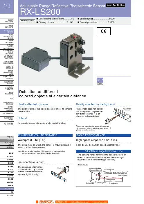
HUMAN MACHINEINTERFACESENERGYMANAGEMENTSOLUTIONSFA COMPONENTSMACHINE VISIONSYSTEMSUV CURINGSYSTEMSCX-400CY-100EX-10EX-20EX-30EX-40CX-440EQ-30EQ-500MQ-WRXRT-610Hardly affected by colorThe color or size of the object does not affect its sensingperformance.Hardly affected by backgroundThe sensor does not detectthe background beyond theset distance since it is ofdistance adjustable type.RobustIts robust enclosure is made of die-cast zinc alloy.High-speed response time: 1 msIt can be used on a high speed assembly line.BASIC PERFORMANCEWaterproof IP67 (IEC)The equipment on which the sensor is mounted can bewashed without any problem.ENVIRONMENTAL RESISTANCENote: H owever, take care that if it is exposed to water splashesduring operation. It may detect a water drop itself.Insusceptible to dustThe sensing performanceis less affected by dust asit does not depend on theincident light intensity.has a specular surface.Adjustable Range Reflective Photoelectric SensorRX-LS200344FIBER SENSORSLASER SENSORS PHOTO-ELECTRIC SENSORS AREA SENSORS SAFETY LIGHT CURTAINS /SAFETY COMPONENTS PRESSURE / FLOW SENSORS INDUCTIVE PROXIMITY SENSORS PARTICULAR USE SENSORS SENSOR OPTIONS SIMPLE WIRE-SAVING UNITS WIRE-SAVING SYSTEMSMEASURE-MENT SENSORS STATIC CONTROL DEVICES LASER MARKERS PLC HUMAN MACHINE INTERFACES ENERGY MANAGEMENT SOLUTIONS FACOMPONENTS MACHINE VISION SYSTEMSUVCURINGSYSTEMSEX-Z CX-400CY-100EX-10 EX-20EX-30EX-40CX-440EQ-30EQ-500RX RT-6105 m cable length type5 m 16.404 ft cable length type (standard: 3 m 9.843 ft ) is also available for NPN output type.Model No.: RX-LS200-C5Accessory• MS-RX-1 (Sensor mounting bracket)Narrow-view slit mask• OS-RXL-□Protective tubeTwo M4 (length 16 mm 0.630 in )hexagon-socket-head bolts are attached.056 222 38 18*********************SEN TRONIC AG345Adjustable Range Reflective Photoelectric Sensor RX-LS200FIBERSENSORSLASERSENSORSPHOTO-ELECTRICSENSORSAREASENSORSSAFETY LIGHTCURTAINS /SAFETYCOMPONENTSPRESSURE /FLOWSENSORSINDUCTIVEPROXIMITYSENSORSPARTICULARUSESENSORSSENSOROPTIONSSIMPLEWIRE-SAVINGUNITSWIRE-SAVINGSYSTEMSMEASURE-MENTSENSORSSTATICCONTROLDEVICESLASERMARKERSPLCHUMANMACHINEINTERFACESENERGYMANAGEMENTSOLUTIONSFACOMPONENTSMACHINEVISIONSYSTEMSUVCURINGSYSTEMSEX-ZCX-400CY-100EX-10EX-20EX-30EX-40CX-440EQ-30EQ-500RXRT-610I/O circuit diagram Wiring diagramSymbols … D : Reverse supply polarity protection diodeZ D : Surge absorption zener diodeTr : NPN output transistor±10 %RX-LS200NPN output type 056 222 38 18*********************SEN TRONICAGAdjustable Range Reflective Photoelectric SensorRX-LS200346FIBER SENSORS LASER SENSORS PHOTO-ELECTRIC SENSORSAREA SENSORS SAFETY LIGHT CURTAINS /SAFETY COMPONENTS PRESSURE / FLOW SENSORS INDUCTIVE PROXIMITY SENSORS PARTICULAR USE SENSORS SENSOR OPTIONS SIMPLE WIRE-SAVING UNITS WIRE-SAVING SYSTEMSMEASURE-MENT SENSORS STATIC CONTROL DEVICES LASER MARKERS PLC HUMAN MACHINE INTERFACES ENERGY MANAGEMENT SOLUTIONS FACOMPONENTS MACHINE VISION SYSTEMS UVCURINGSYSTEMSEX-Z CX-400CY-100EX-10EX-20EX-30EX-40CX-440EQ-30EQ-500RX RT-610I/O circuit diagramWiring diagramNote: T he output does not incorporate a short-circuit protection circuit.Do not connect it directly to a power supply or a capacitive load.Symbols … D : Reverse supply polarity protection diodeZ D : Surge absorption zener diode Tr : PNP output transistorto 24 V DCSensing fields• Setting distance: 200 mm 7.874 in (Horizontal)• Setting distance: 200 mm 7.874 in (Vertical)• Setting distance: 150 mm 5.906 in (Horizontal)• Setting distance: 150 mm 5.906 in (Vertical)• Setting distance: 150 mm 5.906 in with slit mask (Vertical)• Setting distance: 150 mm 5.906 in with slit mask(Horizontal)0.3940.394Left Center in )S e t t i n g d i s t a n c e L (m m i n Up Center Operating point ℓ (mm in )0.3940.394S e t t i n g d i s t a n c e L (m m in Left Center in)0.1570.157S e t t i n g d i s t a n c e L (m mi nUp Center in )0.1570.157S e t t i n g d i s t a n c e L(m m i nLeft Center Operating point ℓ (mm in )0.1570.157S e t t i n g d i s t a n c e L (m m i nUp Operating point ℓ (mm in )0.1570.157S e t t i n g d i s t a n c e L (m m i nCorrelation between sensing object size and sensing range0.787 1.575 2.362 3.1503.937 in , 7.874 in , each, with white non-glossy 1.969 × 1.969 in ).side length a (mm in )S e n s i n g r a n g e L (m m i n D i s t a n c e L (m m i n RX-LS200-P PNP output type056 222 38 18*********************SEN TRONIC AG347Adjustable Range Reflective Photoelectric Sensor RX-LS200FIBERSENSORSLASERSENSORSPHOTO-ELECTRICSENSORSAREASENSORSSAFETY LIGHTCURTAINS /SAFETYCOMPONENTSPRESSURE /FLOWSENSORSINDUCTIVEPROXIMITYSENSORSPARTICULARUSESENSORSSENSOROPTIONSSIMPLEWIRE-SAVINGUNITSWIRE-SAVINGSYSTEMSMEASURE-MENTSENSORSSTATICCONTROLDEVICESLASERMARKERSPLCHUMANMACHINEINTERFACESENERGYMANAGEMENTSOLUTIONSFACOMPONENTSMACHINEVISIONSYSTEMSUVCURINGSYSTEMSEX-ZCX-400CY-100EX-10EX-20EX-30EX-40CX-440EQ-30EQ-500RXRT-610Correlation between material (50 × 50 mm 1.969 × 1.969 in) and sensing range200 mm 7.874 in100 mm 3.937 in50 mm 1.969 inWhitenon-glossypaperPlywoodCardboardCeramiccircuitboardGraynon-glossypaper(Lightness:3)BlackrubbeMirrorThese bars indicate the sensing rangewith respective objects when thedistance adjuster is set at the sensingrange of 200 mm 7.874 in, 100 mm3.937 in and 50 mm 1.969 in long,each, with white non-glossy paper.(GreenmaskedsurfaceGlassepoxyprintedcircuitboardSensingrangeL(mminWiring• The output of RX-LS200-P does not incorporate a short-circuit protection circuit. Do not connect it directly to apower supply or a capacitive load.Others• Do not use during the initial transient time (50 ms) afterthe power supply is switched on.Mounting• The tightening torque should be 1.17 N·m or less.• Care must be taken regarding the sensor mountingdirection with respect to the object’s direction of movement.Do not make the sensordetect an object in thisdirection because it maycause unstable operation.Sensing object Sensing object Sensing objectintersection of the “ ”mark on the lens faceand the “ ” line.• When detecting a specular object (aluminum or copperfoil) or an object having a glossy surface or coating,please take care that there are cases when the objectmay not be detected due to a small change in angle,wrinkles on the object surface, etc.• When a specular body is present below the sensor, usethe sensor by tilting it slightly upwards to avoid wrongoperation.Use conditions to comply with CE Marking• Following work must be done in case of using thisproduct as a CE marking (European standard EMCDirective) conforming product.Ensure that the shield is connected to 0 V or the actualground.• In case of connecting a sensor to power supply 0 V by usinga shield (piping, etc.)• In case of grounding by using a shield (piping, etc.)Note: The shield (piping, etc.) must be insulated.• If a specular body is present in the background, wrongoperation may be caused due to a small change in theangle of the background body. In that case, install thesensor at an inclination and confirm the operation withthe actual sensing object.• Do not install the sensor at a distance of less than 50 mm1.969 in from the object because the sensing is unstablein this range.Correct Correct Incorrect056 222 38 18*********************SEN TRONICAGAdjustable Range Reflective Photoelectric SensorRX-LS200348FIBER SENSORS LASER SENSORS PHOTO-ELECTRIC SENSORS AREA SENSORSSAFETY LIGHT CURTAINS /SAFETY COMPONENTS PRESSURE / FLOW SENSORSINDUCTIVE PROXIMITY SENSORS PARTICULAR USE SENSORSSENSOR OPTIONS SIMPLE WIRE-SAVING UNITS WIRE-SAVING SYSTEMSMEASURE-MENT SENSORS STATIC CONTROL DEVICES LASER MARKERS PLC HUMAN MACHINE INTERFACES ENERGY MANAGEMENT SOLUTIONS FACOMPONENTS MACHINE VISION SYSTEMSUVCURINGSYSTEMSEX-Z CX-400CY-100EX-10 EX-20EX-30EX-40CX-440EQ-30EQ-500RX RT-610Distance adjustmentSensorRX-LS200 RX-LS200-PProtective tube (Optional)PT-RX500 PT-RX1000MS-RX-1Sensor mounting bracket (Accessory)Assembly dimensions• Follow only steps 1 and 2 respectively. Since the sensing point may change depending on the sensing object, be sure to check the operation with the actual sensing object.<When a sensing object is approaching / moving away from the sensor><When a sensing object moves horizontally to the sensor>) hexagon-socket-AdjustersAdjusting procedure056 222 38 18*********************SEN TRONIC AG。
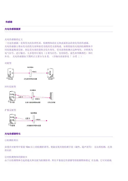
传感器光电传感器概要光电传感器的定义「光电传感器」是利用光的各种性质,检测物体的有无和表面状态的变化等的传感器。
光电传感器主要由发光的投光部和接受光线的受光部构成。
如果投射的光线因检测物体不同而被遮掩或反射,到达受光部的量将会发生变化。
受光部将检测出这种变化,并转换为电气信号,进行输出。
大多使用可视光(主要为红色,也用绿色、蓝色来判断颜色)和红外光。
光电传感器如下图所示主要分为3类。
(详细内容请参见「分类」)对射型回归反射型扩散反射型光电传感器特长①检测距离长如果在对射型中保留10m以上的检测距离等,便能实现其他检测手段(磁性、超声波等)无法离检测。
达到的长距②对检测物体的限制少由于以检测物体引起的遮光和反射为检测原理,所以不象接近传感器等将检测物体限定在金属,它可对玻璃.塑料.木材.液体等几乎所有物体进行检测。
③响应时间短光本身为高速,并且传感器的电路都由电子零件构成,所以不包含机械性工作时间,响应时间非常短。
④分辨率高能通过高级设计技术使投光光束集中在小光点,或通过构成特殊的受光光学系统,来实现高分辨率。
也可进行微小物体的检测和高精度的位置检测。
⑤可实现非接触的检测可以无须机械性地接触检测物体实现检测,因此不会对检测物体和传感器造成损伤。
因此,传感器能长期使用。
⑥可实现颜色判别通过检测物体形成的光的反射率和吸收率根据被投光的光线波长和检测物体的颜色组合而有所差异。
利用这种性质,可对检测物体的颜色进行检测。
⑦便于调整在投射可视光的类型中,投光光束是眼睛可见的,便于对检测物体的位置进行调整。
光电传感器原理①光的性质直射光在空气中和水中时,总是直线传播。
使用对射型传感器外置的开叉来检测微小物体的示例便是运用了这种原理。
曲折是指光射入到曲折率不同的界面上时,通过该界面后,改变行进方向的现象。
反射(正反射、回归反射、扩散反射)在镜面和玻璃平面上,光会以与入射角相同的角度反射,称为正反射。
3个平面互相直角般组合的形状称为三面直角棱镜。
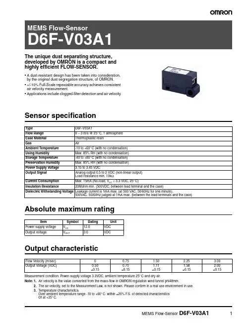
The unique dust separating structure, developed by OMRON is a compact and highly efficient FLOW-SENSOR.•A dust-resistant design has been taken into consideration, by the original dust segregation structure, of OMRON.•+/-10% Full-Scale repeatable accuracy achieves consistent air velocity measurement.•Applications include clogged-filter detection and air velocity.Sensor specificationAbsolute maximum ratingOutput characteristicMeasurement condition: Power-supply voltage 3.3VDC, ambient temperature 25°C and dry air.Note:1.Air velocity is the value converted from the mass-flow in OMRON regulation wind tunnel phi48mm.2.The air velocity, set to the Measurement Law, is not shown. Please confirm in a real use environment in use.3.T emperature characteristics:Over ambient temperature range -10 to +60°C: within ±20% F .S. of detected characteristics Of at +25°C.Type D6F-V03A1Flow Range 0 – 3 m/s @ 25°C, 1 atmosphere Case Material Thermoplastic resin GasAirAmbient Temperature -10 to +60°C (with no condensation)Using Humidity Max. 85% RH (with no condensation)Storage Temperature -40 to +80°C (with no condensation)Preservation Humidity Max. 85% RH (with no condensation)Power Supply Voltage 3.15 to 3.45 VDCOutput Signal Analog output 0.5 to 2 VDC (non-linear output)Load resistance min. 10k ΩCurrent Consumption Max. 15mA (No-load, V CC = 3.3 VDC, 25°C)Insulation Resistance20Mohm min. (500VDC, between lead terminal and the case)Dielectric Withstanding Voltage Leakage current is 1mA max. (at 500 VAC, 50/60Hz for one minute).500VAC, 50/60Hz judged at 1mA max. (between the lead terminals and the case)ItemSymbol Rating Unit Power supply voltage V CC 12.0VDC Output voltageV OUT3.0VDCFlow Velocity (m/sec)00.75 1.50 2.25 3.00Output Voltage (VDC)0.50±0.150.70±0.151.11±0.151.58±0.152.00±0.15DimensionsOmron Electronic Components, LLCTerms and Conditions of Sales1.Definitions: The words used herein are defined as follows.(a) Terms:These terms and conditions(b) Seller:Omron Electronic Components LLC and its subsidiaries(c) Buyer:The buyer of Products, including any end user in section III through VI(d) Products:Products and/or services of Seller(e) Including:Including without limitation2.Offer; Acceptance: These Terms are deemed part of all quotations, acknowledgments,invoices, purchase orders and other documents, whether electronic or in writing, relating to the sale of Products by Seller. Seller hereby objects to any Terms proposed in Buyer's purchase order or other documents which are inconsistent with, or in addition to, these Terms.3.Distributor: Any distributor shall inform its customer of the contents after and includingsection III of these Terms.1.Prices; Payment: All prices stated are current, subject to change without notice by Seller.Buyer agrees to pay the price in effect at time of shipment. Payments for Products received are due net 30 days unless otherwise stated in the invoice. Buyer shall have no right to set off any amounts against the amount owing in respect of this invoice.2.Discounts: Cash discounts, if any, will apply only on the net amount of invoices sent toBuyer after deducting transportation charges, taxes and duties, and will be allowed only if (a) the invoice is paid according to Seller's payment terms and (b) Buyer has no past due amounts owing to Seller.3.Interest: Seller, at its option, may charge Buyer 1.5% interest per month or the maximumlegal rate, whichever is less, on any balance not paid within the stated terms.4.Orders: Seller will accept no order less than 200 U.S. dollars net billing.5.Currencies: If the prices quoted herein are in a currency other than U.S. dollars, Buyershall make remittance to Seller at the then current exchange rate most favorable to Seller; provided that if remittance is not made when due, Buyer will convert the amount to U.S. dollars at the then current exchange rate most favorable to Seller availableduring the period between the due date and the date remittance is actually made.ernmental Approvals: Buyer shall be responsible for all costs involved in obtainingany government approvals regarding the importation or sale of the Products.7.Taxes: All taxes, duties and other governmental charges (other than general real propertyand income taxes), including any interest or penalties thereon, imposed directly orindirectly on Seller or required to be collected directly or indirectly by Seller for themanufacture, production, sale, delivery, importation, consumption or use of the Products sold hereunder (including customs duties and sales, excise, use, turnover and license taxes) shall be charged to and remitted by Buyer to Seller.8.Financial: If the financial position of Buyer at any time becomes unsatisfactory to Seller,Seller reserves the right to stop shipments or require satisfactory security or payment in advance. If Buyer fails to make payment or otherwise comply with these Terms or any related agreement, Seller may (without liability and in addition to other remedies) cancel any unshipped portion of Products sold hereunder and stop any Products in transit until Buyer pays all amounts, including amounts payable hereunder, whether or not then due, which are owing to it by Buyer. Buyer shall in any event remain liable for all unpaid accounts.9.Cancellation; Etc: Orders are not subject to rescheduling or cancellation unless Buyerindemnifies Seller fully against all costs or expenses arising in connection therewith. 10.Force Majeure: Seller shall not be liable for any delay or failure in delivery resulting fromcauses beyond its control, including earthquakes, fires, floods, strikes or other labor disputes, shortage of labor or materials, accidents to machinery, acts of sabotage, riots, delay in or lack of transportation or the requirements of any government authority.11.Shipping; Delivery: Unless otherwise expressly agreed in writing by Seller:(a) All sales and shipments of Products shall be FOB shipping point (unless otherwisestated in writing by Seller), at which point title to and all risk of loss of the Products shall pass from Seller to Buyer, provided that Seller shall retain a security interest in theProducts until the full purchase price is paid by Buyer;(b) Delivery and shipping dates are estimates only; and(c) Seller will package Products as it deems proper for protection against normalhandling and extra charges apply to special conditions.12.Claims: Any claim by Buyer against Seller for shortage or damage to the Productsoccurring before delivery to the carrier must be presented in detail in writing to Seller within 30 days of receipt of shipment.1.Suitability: IT IS THE BUYER’S SOLE RESPOINSIBILITY TO ENSURE THAT ANYOMRON PRODUCT IS FIT AND SUFFICIENT FOR USE IN A MOTORIZED VEHICLE APPLICATION. BUYER SHALL BE SOLELY RESPONSIBLE FOR DETERMINING APPROPRIATENESS OF THE PARTICULAR PRODUCT WITH RESPECT TO THE BUYER’S APPLICATION INCLUDING (A) ELECTRICAL OR ELECTRONICCOMPONENTS, (B) CIRCUITS, (C) SYSTEM ASSEMBLIES, (D) END PRODUCT, (E) SYSTEM, (F) MATERIALS OR SUBSTANCES OR (G) OPERATING ENVIRONMENT.Buyer acknowledges that it alone has determined that the Products will meet theirrequirements of the intended use in all cases. Buyer must know and observe allprohibitions of use applicable to the Product/s.e with Attention: The followings are some examples of applications for whichparticular attention must be given. This is not intended to be an exhaustive list of all possible use of any Product, nor to imply that any use listed may be suitable for any Product:(a) Outdoor use, use involving potential chemical contamination or electricalinterference.(b) Use in consumer Products or any use in significant quantities.(c) Energy control systems, combustion systems, railroad systems, aviation systems,medical equipment, amusement machines, vehicles, safety equipment, andinstallations subject to separate industry or government regulations.(d) Systems, machines, and equipment that could present a risk to life or property.3.Prohibited Use: NEVER USE THE PRODUCT FOR AN APPLICATION INVOLVINGSERIOUS RISK TO LIFE OR PROPERTY WITHOUT ENSURING THAT THE SYSTEM AS A WHOLE HAS BEEN DESIGNED TO ADDRESS THE RISKS, AND THAT THE PRODUCT IS PROPERLY RATED AND INSTALLED FOR THE INTENDED USEWITHIN THE OVERALL EQUIPMENT OR SYSTEM.4.Motorized Vehicle Application: USE OF ANY PRODUCT/S FOR A MOTORIZEDVEHICLE APPLICATION MUST BE EXPRESSLY STATED IN THE SPECIFICATION BY SELLER.5.Programmable Products: Seller shall not be responsible for the Buyer's programming ofa programmable Product.1.Warranty: Seller's exclusive warranty is that the Products will be free from defects inmaterials and workmanship for a period of twelve months from the date of sale by Seller (or such other period expressed in writing by Seller). SELLER MAKES NO WARRANTY OR REPRESENTATION, EXPRESS OR IMPLIED, ABOUT ALL OTHER WARRANTIES, NON-INFRINGEMENT, MERCHANTABILITY OR FITNESS FOR A PARTICULARPURPOSE OF THE PRODUCTS.2.Buyer Remedy: Seller's sole obligation hereunder shall be to replace (in the formoriginally shipped with Buyer responsible for labor charges for removal or replacement thereof) the non-complying Product or, at Seller's election, to repay or credit Buyer an amount equal to the purchase price of the Product; provided that there shall be noliability for Seller or its affiliates unless Seller's analysis confirms that the Products were handled, stored, installed and maintained and not subject to contamination, abuse,misuse or inappropriate modification. Return of any Products by Buyer must beapproved in writing by Seller before shipment.3.Limitation on Liability: SELLER AND ITS AFFILIATES SHALL NOT BE LIABLE FORSPECIAL, INDIRECT, INCIDENTAL OR CONSEQUENTIAL DAMAGES, LOSS OF PROFITS OR PRODUCTION OR COMMERCIAL LOSS IN ANY WAY CONNECTED WITH THE PRODUCTS, WHETHER SUCH CLAIM IS BASED IN CONTRACT,WARRANTY, NEGLIGENCE OR STRICT LIABILITY. FURTHER, IN NO EVENT SHALL LIABILITY OF SELLER OR ITS AFFILITATES EXCEED THE INDIVIDUAL PRICE OF THE PRODUCT ON WHICH LIABILITY IS ASSERTED.4.Indemnities: Buyer shall indemnify and hold harmless Seller, its affiliates and itsemployees from and against all liabilities, losses, claims, costs and expenses (including attorney's fees and expenses) related to any claim, investigation, litigation or proceeding (whether or not Seller is a party) which arises or is alleged to arise from Buyer's acts or omissions under these Terms or in any way with respect to the Products.1.Intellectual Property: The intellectual property embodied in the Products is the exclusiveproperty of Seller and its affiliates and Buyer shall not attempt to duplicate it in any way without the written permission of Seller. Buyer (at its own expense) shall indemnify and hold harmless Seller and defend or settle any action brought against Seller to the extent that it is based on a claim that any Product made to Buyer specifications infringedintellectual property rights of another party.2.Property; Confidentiality: Notwithstanding any charges to Buyer for engineering ortooling, all engineering and tooling shall remain the exclusive property of Seller. All information and materials supplied by Seller to Buyer relating to the Products areconfidential and proprietary, and Buyer shall limit distribution thereof to its trustedemployees and strictly prevent disclosure to any third party.3.Performance Data: Performance data is provided as a guide in determining suitabilityand does not constitute a warranty. It may represent the result of Seller's test conditions, and the users must correlate it to actual application requirements.4.Change In Specifications: Product specifications and description may be changed at anytime based on improvements or other reasons. It is Seller’s practice to change part numbers when published ratings or features are changed, or when significantengineering changes are made. However, some specifications of the Product may be changed without any notice.5.Errors And Omissions: The information on Seller’s website or in other documentationhas been carefully checked and is believed to be accurate; however, no responsibility is assumed for clerical, typographical or proofreading errors or omissions.6.Export Controls: Buyer shall comply with all applicable laws, regulations and licensesregarding (a) export of the Products or information provided by Seller; (b) sale ofProducts to forbidden or other proscribed persons or organizations; (c)disclosure to non-citizens of regulated technology or information.1.Waiver: No failure or delay by Seller in exercising any right and no course of dealingbetween Buyer and Seller shall operate as a waiver of rights by Seller.2.Assignment: Buyer may not assign its rights hereunder without Seller's written consent.w: These Terms are governed by Illinois law (without regard to conflict of laws). Federaland state courts in Illinois have exclusive jurisdiction for any dispute hereunder.4.Amendment: These Terms constitute the entire agreement between Buyer and Sellerrelating to the Products, and no provision may be changed or waived unless in writing signed by the parties.5.Severability: If any provision hereof is rendered ineffective or invalid, such provision shallnot invalidate any other provision.Certain Precautions on Specifications and UseOMRON ON-LINEGlobal - USA - Cat. No. J01C-E-01Printed in USAOMRON ELECTRONIC COMPONENTS LLC55 E. Commerce Drive, Suite B Schaumburg, IL 60173847-882-228801/07 Specifications subject to change without noticeComplete “Terms and Conditions of Sale” for product purchase and use are on Omron’s website at – under the “About Us” tab, in the Legal Matters section.ALL DIMENSIONS SHOWN ARE IN MILLIMETERS.T o convert millimeters into inches, multiply by 0.03937. To convert grams into ounces, multiply by 0.03527.。
长距离检测型单光束安全传感器F3SSᅝܼ Ӵᛳ఼相关信息 产品线...................................F-26 共通注意事项 ........................ 后-2 技术指南 ................................ 46560m的长距离检测。
最适合于流水线上整体的防护及大型设备的 多面侵入检测等人体检测用(4级)的对射型光电传感器■最多4套可防止相互间干扰 ■符合IEC标准,北美标准 (已取得IEC61496-1、 -2、 UL/CSA标准的认证) 可以作为北美劳动安全现场所必须的OSHA规范中规定的安全防护装置使用 ■不需要专用控制器。
只用传感器便可实现人体侵入检测功能 ■具有防止输出自动复位的 “启动/重启互锁功能” 。
F3SJ F3SN-A F3SN-B F3SH-A F3SL■投/受光透镜上安装加热器。
■即使在发生结露的环境下也可以安心使用 ■备有玻璃制和不锈钢制的反射镜作为可选件请参照294页 「请正确使用」 。
E3FS E3ZS F3SS种类主体检测方式 形状 外壳材质 连接方法 内部基板上的 端子台连接 检测距离 输出规格 组合型号(交货期请向经销商咨询)㑶ܝ对射型铝0.360mPNP输出F3SS-AT60P注. 投光器:F3SS-AT60P-L受光器:F3SS-AT60-D也可以单独订购。
附件(另售)种类 激光校准工具(光轴调整用) 玻璃反射镜 不锈钢反射镜 45度反射镜金属安装配件 墙壁用反射镜金属安装配件 φ42圆柱传感器金属安装配件注. 配线是内置端子台方式。
请另行准备配线用φ4~φ7电缆。
型号 F39-LLK F39-MSG F39-MSS F39-LM45 F39-LA F39-LSP290长距离检测型单光束安全传感器F3SS额定值/性能项目 检测方式 外壳材质 连接方法 电源电压 有效开口角 消耗电流 检测距离 标准检测物体 响应时间 控制输出 型号 F3SS-AT60P 对射型 铝(外壳、盖) 由内部基板上的端子台连接 DC24V±10% 波纹(p-p) ±2.5°(3m的情况下) 投光器:170mA以下 受光器:800mA以下 0.3~60m φ31mm以上的不透明体 35ms以下 PNP晶体管输出×2输出 负载电流:250mA输出残留电压1V以下(因导线延长的电压降除外) 入光时ON 自动启动模式 启动互锁模式 启动/重启互锁模式 用受光器内的切换开关可以选择任一模式 4s以内 工作时·保存时:各0~+55℃ (不结冰、不结露) 工作时·保存时:各35~95%RH (不结冰、不结露) 误操作·耐久:10~55Hz 双振幅0.77mmX、 Y、 Z各方向20次 误操作·耐久:100m/s2X、 Y、 Z各方向1000次 IEC标准IP65 红外发光二极管(880nm) 投光器:橙/表示电源、红/表示故障 受光器:橙/表示光量、红/表示遮光、绿/表示投光、黄/表示互锁 电源接反保护、负载短路保护 约2.5kg(1套) IEC(EN)61496-1 Type4 ESPE *1 IEC(prEN)61496-2 Type4 AOPD *2 使用说明书、金属安装配件一套、导管用盖ᅝܼ Ӵᛳ఼工作模式 电源接通后启动时间 环境温度 环境湿度 耐振动 耐冲击 保护结构 光源 表示 保护电路 重量(包装状态) 适用标准 附件F3SJ F3SN-A F3SN-B F3SH-A F3SLE3FS E3ZS F3SS*1. Electro-Sensitive Protective Equipment *2. Active Opto-electronic Protective Device连接将所有的电源切断之后,进行F3SS的配线。
欧姆龙接近传感器常见问题接近开关和OMRON的PLC怎么接线?:直流二线型:褐色线接PLC输入点,PLC的com点接到电源正极,电源负极接到蓝色线。
NPN型:褐色接电源正,蓝色接电源负,黑色线接到PLC输入点,PLC的com点接到电源正。
NPN是漏型,检测到物体时输出低电平信号。
PNP型:褐色接电源正,蓝色接电源负,黑色线接到PLC输入点,PLC的com点接到电源负。
PNP是源型,检测到物体时输出高电平信号。
接近传感器可以检测哪些物体?:接近传感器的被测物体分为磁性金属(如铁、镍等),非磁性金属(如黄铜、铝等)和非金属(如塑料、玻璃、水等)。
接近传感器按照检测原理分为电感型和电容型。
电感型接近传感器(如E2E)只能检测金属,不能检测非金属。
电容型接近传感器(如E2K)可以检测金属和非金属。
以上两种类型的接近传感器根据被测物体材质的不同,检测距离也不同E2E-□□□和E2E-□□□-N的区别是什么?:-N有新版本的意思,并且在具体的规格、性能上与没有-N的产品有区别。
E2E-X2D1的外径是M12,响应频率800Hz。
E2E-X2D1-N的外径是M8,响应频率是1500Hz。
传感器的长度也不完全一样,除这些外的其余参数相同。
接近传感器有误动作现象,如何解决?:请按照以下步骤排故:①稳定电源给接近传感器单独供电;②响应频率在额定范围内;③物体检测过程中有抖动,导致超出检测区域;④多个探头紧密安装互相干扰;⑤传感器探头周围的检测区域内有其他被测物体;⑥接近传感器的周围有大功率设备,有电气干扰。
接近传感器检测到被测物体后续设备都不动作,为什么?:接近传感器分两种,电感型和静电容型,分别按照以下步骤排故。
电感型:①供电电压要在额定范围内;②被测物体是金属,大小尺寸足以让传感器可以检测到;③被测物体在传感器检测的有效范围内;④传感器是常开还是常闭;⑤和后续设备接线方式正确,信号匹配;⑥接近传感器的开关容量足够驱动后续设备。

OMRON欧姆龙光电传感器OMRON欧姆龙公司是一家专业从事电器控制、电子设备和自动化技术的日本企业。
公司成立于1933年,随着科技的发展与市场需求的变化,OMRON欧姆龙公司已经逐渐成为全球领先的电气制造商之一。
它的光电传感器是其自动化技术产品中的重要组成部分。
什么是光电传感器?光电传感器是一种常见的传感器类型,其工作原理基于光的特性。
它利用发射器发射出的光束,通过被检测物体反射回来或者经过物体时发生光电反应,进而判断物体是否存在或者物体的某种信息。
光电传感器常用于自动化检测和测量中,能够替代人工进行物体检测和计数的工作。
光电传感器根据测量光源、检测方式、输出方式等不同标准进行分类。
其中,OMRON欧姆龙光电传感器主要用于物体检测和测距等领域,并且在不同场合中选用不同种类的光电传感器。
OMRON欧姆龙光电传感器的特点1. 精度高OMRON欧姆龙光电传感器能够对物体进行快速、准确的检测,可以测量到微小物体,其测量精度高于通常的机械传感器。
同时,它的检测距离也具有较高的可调节性,可以根据实际需求进行灵活的调整。
2. 适用范围广OMRON欧姆龙光电传感器能够应用于各种不同的环境和场合。
例如,它可以用于在加工生产中检测个体物体或者线体,也可以用于自动售货机中物品的检测。
3. 反应时间短OMRON欧姆龙光电传感器反应时间快,达到亚毫秒级别。
这要归功于其光电传感技术的高速度与高效性。
4. 安全性高OMRON欧姆龙光电传感器使用低功率发射器,可以保证在使用过程中的安全性。
其次,当检测到异常情况时,光电传感器也能够立即停止工作,从而保障生产安全。
适用场合OMRON欧姆龙光电传感器广泛应用于机械加工、自动化流水线、食品加工、物流包装等领域。
通过其高效、准确的检测,可以提高生产效率并降低成本,同时还能确保产品质量和安全性。
例如,在食品加工业中,OMRON欧姆龙的光电传感器可以对水果、蔬菜、肉类和大米等进行检测,控制流水生产线上的物料充实度、等级是否符合标准、存在异物等问题,提高了加工线的质量和安全性。

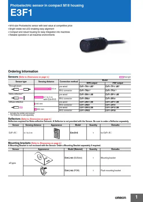
1•M18 size Photoelectric sensor with best value at competitive price •Bright visible red LED enabling easy alignment•Compact and robust housing for easy integration into machines •Reliable operation in all industrial environmentsOrdering InformationSensors [Refer to Dimensions on page 5.]Reflectors [Refer to Dimensions on page 6.]Reflectors required for Retro-reflective Sensors: A Reflector is not provided with the Sensor. Be sure to order a Reflector separately.Mounting brackets [Refer to Dimensions on page 6.]A Mounting Bracket is not enclosed with the Sensor. Order a Mounting Bracket separately if required.*2The Reflector is sold separately.Red lightSensorSensing distanceAppearanceModelQuantityRemarksE 3F1-R @0.1 to 3 m E39-R1S 1for E 3F1-R @E3F12Sensor I/O connectorsModels for Connectors: A Connector is not provided with the Sensor. Be sure to order a Connector separately. SpecificationsSensor Size Cable Appearance Cable type ModelM12 connector types M12S tandard2 m4-wireXS2F-M12PVC4S2M-EU5 m XS2F-M12PVC4S5M-EU2 m XS2F-M12PVC4A2M-EU5 m XS2F-M12PVC4A5M-EUSensing method Through-beam Retro-reflective Diffuse-reflective Model NPNoutputPre-wired E3F1-TN11 2M E3F1-RN11 2M E3F1-DN11 2M E3F1-DN12 2MM12 Connector E3F1-TN21E3F1-RN21E3F1-DN21E3F1-DN22 PNPoutputPre-wired E3F1-TP11 2M E3F1-RP11 2M E3F1-DP11 2M E3F1-DP12 2MItem M12 Connector E3F1-TP21E3F1-RP21E3F1-DP21E3F1-DP22Sensing distance15 m0.1 to 3 m(with E39-R1S)100 mm(white paper:300⨯300mm)300 mm(white paper:300⨯300mm)Spot diameter (typical)——40 ⨯ 45 mmS ensing distanceof 100 mm40 ⨯ 50 mmS ensing distanceof 300 mmDirectional angle2° min.2° min.——Light source (wavelength)Red LED (624 nm)Power supply voltage10 to 30 VDC (include voltage ripple of 10%(p-p) max.)Current consumption40 mA max.(Emitter 25 mA max.Receiver 15 mA max.)25 mA max.Control outputNPN/PNP (open collector)Load current: 100 mA max. (Residual voltage: 3 V max.), Load power supply voltage: 30 VDC max. Operation mode Light-ON/Dark-ON selectable by wiringIndicatorOperation indicator (orange)S tability indicator (green)Power indicator (green): only Emitter of Through-beamProtection circuitsReversed power supply polarity protection, Output short-circuit protection and Reversed output po-larity protectionResponse time0.5 msSensitivity adjustment One-turn adjusterAmbient temperature range Operating: -25 to 55°C/ S torage: -30 to 70°C (with no icing or condensation)Ambient humidity range Operating: 35 to 85%RH/ S torage: 35 to 95%RH (with no condensation)Degree of protection IEC: IP66Weight(packedstate/onlysensor)Pre-wired cable (2M)Approx. 110 g/Approx. 50 g,respectivelyApprox. 60 g/ Approx. 50 gConnectorApprox. 30 g/Approx. 10 g,respectivelyApprox. 20 g/ Approx. 10 gMaterialCase AB SLens and Display PMMAAdjuster POMNut AB SAccessoriesInstruction sheetM18 nuts (4 pcs)Instruction sheetM18 nuts (2 pcs)S traightAngleE3F13Output circuit diagramPNP OutputNPN OutputConnector Pin ArrangementM12 Connector Pin ArrangementConnectors (Sensor I/O connectors)M12 4-wire Connectors3124Classification Wire color Connector pin No.Application DCBrown ➀Power supply (+V)White ➁L/on · D/on selectable Blue ➂Power supply (0 V)Black➃OutputE3F14Nomenclature*The Emitter has two Power indicators (Green) instead of the S tability indicator (Green) and the Operation indicator (Orange).Safety PrecautionsRefer to Warranty and Limitations of Liability.This product is not designed or rated for directly orindirectly ensuring safety of persons. Do not use itfor such a purpose.Never use the product with an AC power supply.Do not use the product with voltage in excess of therated voltage.Do not use the product with incorrect wiring.Otherwise, explosion, fire, malfunction may result.Be sure to follow the safety precautions below for added safety.1.Do not use the sensor under the environment with explosive,flammable or corrosive gas.2.Do not use the sensor under the oil or chemical environment.3.Do not use the sensor in the water, rain or outdoors.4.Do not use the sensor in the environment where humidity is highand condensation may occur.5.Do not use the sensor under the environment under the otherconditions in excess of rated.6.Do not use the sensor in place that is exposed by direct sunlight.7.Do not use the sensor in place where the sensor may receivedirect vibration or shock.8.Do not use the thinner, alcohol, or other organic solvents.9.Never disassemble, repair nor tamper with the sensor.10.Please process it as industrial waste.ying S ensor wiring in the same conduit or duct as high-voltagewires or power lines may result in malfunction or damage due toconduit or use shielded cable.2.Do not pull on the cable with excessive force.3.If a commercial switching regulator is used, ground the FG (frameground) terminal.4.The sensor will be available 100 ms after the power supply is tunedON. S tart to use the sensor 100 ms or more after turning ON thepower supply. If the load and the sensor are connected to separatepower supplies, be sure to turn ON the sensor first.5.Output pulses may be generated even when the power supply isOFF. Therefore, it is recommended to first turn OFF the powersupply for the load or the load line.6.The sensor must be mounted using the provided nuts. The propertightening torque range is between 0.4 and 0.5 N·m.St ab ility indic a tor(Green)Oper a tion indic a tor(Or a nge)Sen s itivity a dj us terStraightwith an adjuster:E3F1-T@-DE3F1-R@E3F1-D@without an adjuster:E3F1-T@-L *WARNINGCAUTIONPrecautions for Safe UsePrecautions for Correct UseE3F15DimensionsSensors(Unit: mm)Tolerance class IT16 applies to dimensions in this data sheet unless otherwise specified.dia.0 (AWG26)standard length 2 mPre-wired Models E3F1-T @E3F1-R @E3F1-D @Suitable models E3F1-T @11Suitable models E3F1-R @11E3F1-D @1@*Suitable models E3F1-T @11-D E3F1-R @12E3F1-D @1@Mounting HolesLeft side viewLeft side viewFront viewM12 Connector Models E3F1-T @E3F1-R @E3F1-D@dia.0Suitable models E3F1-T @21Suitable models E3F1-R @21E3F1-D @2@Mounting HolesTerminal No.Specification1+V 2L/on · D/on selectable 30V 4Output*Suitable models E3F1-T @21-D E3F1-R @22E3F1-D @2@Left side viewLeft side viewFront viewRight side viewAttached nutE3F16Accessories (Order Separately)E3F17Read and Understand This CatalogPlease read and understand this catalog before purchasing the products. Please consult your OMRON representative if you have any questions orcomments.WARRANTYOMRON's exclusive warranty is that the products are free from defects in materials and workmanship for a period of one year (or other period if specified) from date of sale by OMRON.OMRON MAKES NO WARRANTY OR REPRESENTATION, EXPRESS OR IMPLIED, REGARDING NON-INFRINGEMENT, MERCHANTABILITY, OR FITNESS FOR PARTICULAR PURPOSE OF THE PRODUCTS. ANY BUYER OR USER ACKNOWLEDGES THAT THE BUYER OR USER ALONE HAS DETERMINED THAT THE PRODUCTS WILL SUITABLY MEET THE REQUIREMENTS OF THEIR INTENDED USE. OMRON DISCLAIMS ALL OTHER WARRANTIES, EXPRESS OR IMPLIED.LIMITA TIONS OF LIABILITYOMRON SHALL NOT BE RESPONSIBLE FOR SPECIAL, INDIRECT, OR CONSEQUENTIAL DAMAGES, LOSS OF PROFITS OR COMMERCIAL LOSS IN ANY WAY CONNECTED WITH THE PRODUCTS, WHETHER SUCH CLAIM IS BASED ON CONTRACT, WARRANTY, NEGLIGENCE, OR STRICT LIABILITY.In no event shall the responsibility of OMRON for any act exceed the individual price of the product on which liability is asserted.IN NO EVENT SHALL OMRON BE RESPONSIBLE FOR WARRANTY, REPAIR, OR OTHER CLAIMS REGARDING THE PRODUCTS UNLESSOMRON'S ANALYSIS CONFIRMS THAT THE PRODUCTS WERE PROPERLY HANDLED, STORED, INSTALLED, AND MAINTAINED AND NOTSUBJECT TO CONTAMINATION, ABUSE, MISUSE, OR INAPPROPRIATE MODIFICATION OR REPAIR.SUITABILITY FOR USEOMRON shall not be responsible for conformity with any standards, codes, or regulations that apply to the combination of products in the customer's application or use of the products.At the customer's request, OMRON will provide applicable third party certification documents identifying ratings and limitations of use that apply to the products. This information by itself is not sufficient for a complete determination of the suitability of the products in combination with the end product, machine, system, or other application or use.The following are some examples of applications for which particular attention must be given. This is not intended to be an exhaustive list of all possible uses of the products, nor is it intended to imply that the uses listed may be suitable for the products:•Outdoor use, uses involving potential chemical contamination or electrical interference, or conditions or uses not described in this catalog.•Nuclear energy control systems, combustion systems, railroad systems, aviation systems, medical equipment, amusement machines, vehicles, safety equipment, and installations subject to separate industry or government regulations.•Systems, machines, and equipment that could present a risk to life or property.Please know and observe all prohibitions of use applicable to the products.NEVER USE THE PRODUCTS FOR AN APPLICATION INVOLVING SERIOUS RISK TO LIFE OR PROPERTY WITHOUT ENSURING THAT THESYSTEM AS A WHOLE HAS BEEN DESIGNED TO ADDRESS THE RISKS, AND THAT THE OMRON PRODUCTS ARE PROPERLY RATED ANDINSTALLED FOR THE INTENDED USE WITHIN THE OVERALL EQUIPMENT OR SYSTEM.PROGRAMMABLE PRODUCTSOMRON shall not be responsible for the user's programming of a programmable product, or any consequence thereof.CHANGE IN SPECIFICA TIONSProduct specifications and accessories may be changed at any time based on improvements and other reasons.It is our practice to change model numbers when published ratings or features are changed, or when significant construction changes are made.However, some specifications of the products may be changed without any notice. When in doubt, special model numbers may be assigned to fix or establish key specifications for your application on your request. Please consult with your OMRON representative at any time to confirm actualspecifications of purchased products.DIMENSIONS AND WEIGHTSDimensions and weights are nominal and are not to be used for manufacturing purposes, even when tolerances are shown.PERFORMANCE DA TAPerformance data given in this catalog is provided as a guide for the user in determining suitability and does not constitute a warranty. It may represent the result of OMRON’s test conditions, and the users must correlate it to actual application requirements. Actual performance is subject to the OMRONWarranty and Limitations of Liability.ERRORS AND OMISSIONSThe information in this document has been carefully checked and is believed to be accurate; however, no responsibility is assumed for clerical,typographical, or proofreading errors, or omissions.Cat. No. E94E-EN-01In the interest of product improvement, specifications are subject to change without notice. OMRON EUROPE B.V.Wegalaan 67-69,NL-2132 JD, Hoofddorp,The NetherlandsPhone:+31 23 568 13 00Fax:+31 23 568 13 88www.industrial.omron.eu。
omron传感器工作原理Omron传感器是工业自动化领域中的一种重要设备,它们被广泛应用于各种工业应用中,如机器人、自动化生产线、安全控制等。
Omron传感器的工作原理是什么?本文将详细介绍Omron传感器的工作原理,帮助读者更好地理解其工作特性。
一、什么是Omron传感器?Omron传感器是日本Omron公司生产的各种类型传感器,包括光电传感器、距离传感器、压力传感器、温度传感器等。
这些传感器具有不同的功能和应用范围,被广泛应用于各种工业设备和系统中。
1. 光电传感器:光电传感器是基于光电效应工作的。
它包括一个光源(如发光二极管)和一个光接收器(如光敏电阻)。
当光源发出光时,光线会照射到光接收器上,导致其电阻值发生变化,从而产生一个电信号。
根据电阻值的变化,光电传感器可以检测物体的存在、移动或颜色等。
2. 距离传感器:距离传感器基于超声波或激光测距原理。
它通过发出超声波或激光光束,测量反射时间或光程来计算物体之间的距离。
距离传感器可以用于控制自动对焦、调节屏幕亮度、检测物体移动等。
3. 压力传感器:压力传感器通过测量物体施加在传感器上的压力来工作。
它们通常使用应变片或压电材料来感应压力,并将压力转换为电信号。
压力传感器可以用于测量气体或液体的压力、温度和粘度等。
4. 温度传感器:温度传感器通过测量物体的温度来工作。
它们通常使用热电偶、热电阻或半导体材料来感应温度变化,并将温度转换为电信号。
温度传感器可以用于控制系统温度、检测过热等。
三、Omron传感器的应用1. 机器人控制:Omron传感器被广泛应用于机器人控制中,如视觉传感器用于识别物体、距离传感器用于避障等。
这些传感器使得机器人能够更加智能和灵活地执行任务。
2. 自动化生产线:Omron传感器被广泛应用于自动化生产线中,如光电传感器用于检测物体的位置和颜色、压力传感器用于控制生产线的速度等。
3. 安全控制:Omron传感器也被广泛应用于安全控制中,如温度传感器用于检测过热、烟雾探测器用于检测烟雾和气体等。
MEMS Thermal SensorsD6TContactless measurementcreating energy-efficient and comfortable living spacesMEMS Thermal Sensors D6THigh Accuracy, Smaller Footprint, East to Work WithOMRON's unique MEMS technology allows combining thermopile elements and ASICs into one package resulting to ultra-compact footprint.Infrared rayAchieving the highest level of SNR* in the world ** SNR: Signal-to-Noise Ratio. Compares the level of a signal to the level of background noise *2 As of December 2017, according to OMRON researchConverts sensor signal to digital temperature output allowing easy use of microcontrollerSpace-saving design,well-suited for embedded applicationsEasy connectionCompact sizeSilicon lens far-infrared focusingDetection principleThermopileHot junctionInfrared ray Cold junctionMEMS Thermal (IR* sensor) measures the surface temperature of objects without touching them when the thermopile element absorbs the amount of radiant energy from the object.*IR: Infrared RayLow noiseCross-section view of D6T sensorThe sensor utilizes the seebeck effect in which thermoelectric force is generated due to the temperature difference that occurs 3Detection results of temperature distribution5MEMS Thermal Sensors D6TObject DetectionD6T sensors can detect objects by pinpointing the target object temperature.6D6T sensor meets customer needs byproviding a wide range of application support from home appliances to industrial use.D6T sensors let you measure temperature without the need to physically touch the object.This allows measuring temperature where it was not possible for contact thermal sensors due to space shortage.The sensors can be used in a wide range of applications including FEMS (Factory EnergyManagement System).7MEMS Thermal Sensors D6TComparison with Pyroelectric SensorAble to detect human (object) motionUnable to detect stationary human (object) presenceAble to detect human (object) motionAble to detect both stationary and motion state of humans (objects).Both the pyroelectric sensor and non-contact MEMS thermal sensor can detect even the slightest amount of radiant energy from objects such as infrared radiation and convert them into temperaturereadings. However, unlike pyroelectric sensor that relies on motion detection, non-contact MEMS thermal sensor is able to detect the presence of stationary humans (or objects).Converts temperature readings only when detecting “temperature changes in the radiant energy” in its field of view.Converts temperature readings by “continuously detecting the temperature of radiant energy” in its field of view8X = 58.0°Y = 58.0°X = 111cmY = 111cmX = 222cmY = 222cmX = 333cmY = 333cmX = 47cmY = 47cmX = 94cmY = 94cmX = 141cmY = 141cmX = 103cmY = 10cmX = 206cmY = 20cmX = 309cmY = 30cmX = 81cmY = 84cmX = 162cmY = 169cmX = 244cmY = 253cmX = 200cmY = 200cmX = 400cmY = 400cmX = 600cmY = 600cm1(1x1)8(1x8)16(4x4)X = 26.5°Y = 26.5°X = 54.5°Y = 5.5°X=44.2°Y=45.7°1024(32x32)X=90.0°Y=90.0°Viewing Angle and Measurement AreaChoose your preferred sensor viewing angle to meet your application needs.* The sizes of measurement area indicated above are for reference only.* The size of measurement area changes according to sensor mounting angle.DistanceNumber ofelementsAppearanceSize ofmeasurementareaDistance 1mDistance 2mDistance 3mNumber ofelementsX-directionY-directionDistance Distance Distance910D 6THigh Sensitivity Enables Detection of Stationary Human Presence•OMRON’s unique MEMS and ASIC technology achieve a high SNR.•Superior noise immunity with a digital output.•High-precision area temperature detection with low cross-talk field of view characteristics.Ordering InformationThermal SensorsAccessories (Sold separately)Model Number Legend(1) Number of elements 44L : 16 (4 ✕ 4)8L : 8 (1 ✕ 8)1A : 1 (1 ✕ 1)32L : 1024 (32 ✕ 32)(2) Viewing angle06: X direction=44.2°, Y direction=45.7°09: X direction=54.5°, Y direction=5.5°01: X direction, Y direction=58.0°02: X direction, Y direction=26.5°01A : X direction, Y direction=90.0°(3) Special Functions H : High-temperature type Non-display : Standard sensorRoHS CompliantRefer to Safety Precautions on page 17.Type Model Cable HarnessD6T-HARNESS-0211D6TMEMS Thermal SensorsD 6TRatings, Specifications, and FunctionsRatingsCharacteristicsFunctions*1.Refer to Field of View Characteristics .*2.Refer to Object Temperature Detection Range .*3.Reference data*4.Taken to be the average value of the central 4 pixels.ItemModelD6T-44L-06/06HD6T-8L-09/09HD6T-1A-01D6T-1A-02D6T-32L-01A Power supply voltage 4.5 to 5.5 VDC Storage temperature range -10 to 60°C -20 to 80°C-20 to 80°C-40 to 80°C -20 to 80°C (with no icing or condensation)Operating temperature range 0 to 50°C 0 to 60°C 0 to 60°C-40 to 80°C -10 to 70°C (with no icing or condensation)Storage humidity range 85% max.95% max.95% max.95% max.95% max.(with no icing or condensation)Operating humidity range20% to 85%20% to 95%20% to 95%20% to 95%20% to 95%(with no icing or condensation)Item Model D6T-44L-06/06H D6T-8L-09/09H D6T-1A-01D6T-1A-02D6T-32L-01AView angle *1X direction 44.2°54.5°58.0°26.5°90°Y direction45.7°5.5°58.0°26.5°90°Object temperature output accuracy *2Accuracy 1±1.5°C max.Measurement conditions: Vcc = 5.0 V (1) Tx = 25°C, Ta = 25°C (2) Tx = 45°C, Ta = 25°C (3) Tx = 45°C, Ta = 45°CWithin ±3.0°CMeasurementconditions: Vcc = 5.0 V Tx = 25°C, Ta = 25°C Central 16-pixel area Accuracy 2±3.0°C max.Measurement conditions: Vcc = 5.0 V (4) Tx = 25°C, Ta = 45°C Within ±5.0°C Measurementconditions: Vcc = 5.0 V Tx = 80°C, Ta = 25°C Central 16-pixel areaCurrent consumption5 mA typical3.5 mA typical19 mA typicalItemModelD6T-44L-06/06H D6T-8L-09/09H D6T-1A-01D6T-1A-02D6T-32L-01A Object temperature detection range *25 to 50°C/5 to 200°C 5 to 50°C/5 to 200°C 5 to 50°C -40 to 80°C 0 to 200°C Reference temperature detection range *25 to 45°C5 to 45°C5 to 45°C-40 to 80°C0 to 80°COutput specifications Digital values that correspond to the object temperature (Tx) and reference temperature(Ta) are output from a serial communications port.Output formBinary code (10 times the detected temperature (°C))Communications formI2C compliant Temperature resolution (NETD) *30.06°C0.03°C0.02°C0.06°C0.33°C *412D6TMEMS Thermal SensorsD 6TObject Temperature Detection RangeD6T-44L-06, D6T-8L-09, D6T-1A-01D6T-44L-06H, D6T-8L-09HD6T-1A-02D6T-32L-01AConnectionsThermal Sensor Configuration Diagram<D6T-8L-09/09H>Note:The D6T-44L-06/06H has pixels 0 to 15.The D6T-1A-01/02 has pixel 0.The D6T-32L-01A has pixel 0 to 1023.Terminal Arrangement: Object temperature detection range5101520253035404550-10020406080100120140160180200Object temperature Tx (°C)R e f e r e n c e t e m p e r a t u r e T a (°C )Object temperature Tx (°C)R e f e r e n c e t e m p e r a t u r e Ta (°C ): Object temperature detection range-10102030405060708090-10020406080100120140160180200Terminal NameFunctionRemarks1GND Ground2VCC Positive power supply voltage input 3SDA Serial data I/O line Connect the open-drain SDA terminal to a pull-up resistor.4SCLSerial clock inputConnect the open-drain SCL terminal to a pull-up resistor.13D6TMEMS Thermal SensorsD 6TField of View CharacteristicsD6T-44L-06/06HField of view in X Directionence, the angular range where the Sensor output is 50% or higher whenthe angle of the Sensor is changed is defined as the view angle.X directionY direction++−−P0P4P1 P5P2 P6P3P7D6T-8L-09/09HField of view in X DirectionField of view in Y DirectionDetection Area for Each PixelNote:Definition of view angle: Using the maximum Sensor output as a refer-ence, the angular range where the Sensor output is 50% or higher whenthe angle of the Sensor is changed is defined as the view angle.14D6TMEMS Thermal SensorsD 6TD6T-1A-01Field of view in X DirectionField of view in Y DirectionDetection Area for Each PixelD6T-1A-02Field of view in X DirectionField of view in Y DirectionNote:Definition of view angle: Using the maximum Sensor output as a refer-ence, the angular range where the Sensor output is 50% or higher when the angle of the Sensor is changed is defined as the view angle.D6T-32L-01AField of view in X DirectionField of view in Y DirectionDetection Area for Each PixelNote:Definition of view angle: Using the maximum Sensor output as a refer-ence, the angular range where the Sensor output is 50% or higher when the angle of the Sensor is changed is defined as the view angle.15D6TMEMS Thermal SensorsD 6TDimensions (Unit: mm)Note:Unless otherwise specified, a tolerance of ±0.3 mm applies to all dimensions.D6T-44L-06/06HSupporting and Mounting Area (Shaded Portion)Top ViewNote:Due to insulation distance limitations, donot allow metal parts to come into contactwith the Sensor.D6T-8L-09/09HSupporting and Mounting Area (Shaded Portion)Note:Due to insulation distance limitations, donot allow metal parts to come into contact with the Sensor.16D6TMEMS Thermal SensorsD 6TD6T-1A-01/02Supporting and Mounting Area (Shaded Portion)Top Viewmetal parts to come into contact with the Sensor.17D6TMEMS Thermal SensorsD 6TSafety Precautions●Installation•The Sensor may not achieve the characteristics given in this datasheet due to the ambient environment or installation loca-tion. Before using the Sensor, please acquire an adequate understanding and make a prior assessment of Sensor char-acteristics in your actual system.●Operating Environment•Do not use the Sensor in locations where dust, dirt, oil, and other foreign matter will adhere to the lens. This may prevent correct temperature measurements.•Do not use the Sensor in any of the following locations.•Locations where the Sensor may come into contact with water or oil •Outdoors•Locations subject to direct sunlight.•Locations subject to corrosive gases (in particular, chlo-ride, sulfide, or ammonia gases).•Locations subject to extreme temperature changes •Locations subject to icing or condensation.•Locations subject to excessive vibration or shock.●Noise Countermeasures•The Sensor does not contain any protective circuits. Never subject it to an electrical load that exceeds the absolute maxi-mum ratings for even an instance. The circuits may be dam-aged. Install protective circuits as required so that the absolute maximum ratings are not exceeded.•Keep as much space as possible between the Sensor anddevices that generates high frequencies (such as high-frequency welders and high-frequency sewing machines) or surges.•Attach a surge protector or noise filter on nearby noise-generating devices (in particular, motors, transformers, solenoids, magnetic coils, or devices that have an inductance component).•In order to prevent inductive noise, separate the connector of the Sensor from power lines carrying high voltages or large currents. Using a shielded line is also effective.•If a switching requlator is used, check that malfunctions will not occur due to switching noise from the power supply.●Handling•This Sensor is a precision device. Do not drop it or subject it to excessive shock or force. Doing so may damage the Sensor or change its characteristics. Never subject the connector to unnecessary force. Do not use a Sensor that has been dropped.•Take countermeasures against static electricity before you handle the Sensor.•Turn OFF the power supply to the system before you install the Sensor. Working with the Sensor while the power supply is turned ON may cause malfunctions.•Secure the Sensor firmly so that the optical axis does not move.•Install the Sensor on a flat surface. If the installation surface is not even, the Sensor may be deformed, preventing correct measurements.•Do not install the Sensor with screws. Screws may cause the resist to peel from the board. Secure the Sensor in a way that will not cause the resist to peel.•Always check operation after you install the Sensor.•Use the specified connector (GHR-04 from JST) and connect it securely so that it will not come off. If you solder directly to the connector terminals, the Sensor may be damaged.•Make sure to wire the polarity of the terminals correctly. Incor-rect polarity may damage the Sensor.•Never attempt to disassemble the Sensor.•Do not use the cable harness to the other product.Precautions for Correct Use18Terms and Conditions AgreementRead and understand this catalog.Please read and understand this catalog before purchasing the products. Please consult your OMRON representative if you have any questions or comments.Warranties.(a) Exclusive Warranty. Omron’s exclusive warranty is that the Products will be free from defects in materials and workmanshipfor a period of twelve months from the date of sale by Omron (or such other period expressed in writingby Omron). Omron disclaims all other warranties, express or implied.(b) Limitations. OMRON MAKES NO WARRANTY OR REPRESENTATION, EXPRESS OR IMPLIED, ABOUTNON-INFRINGEMENT, MERCHANTABILITY OR FITNESS FOR A P ARTICULAR PURPOSE OF THEPRODUCTS. BUYER ACKNOWLEDGES THAT IT ALONE HAS DETERMINED THAT THE PRODUCTS WILLSUITABL Y MEET THE REQUIREMENTS OF THEIR INTENDED USE.Omron further disclaims all warranties and responsibility of any type for claims or expenses based on infringement by the Products or otherwise of any intellectual property right. (c) Buyer Remedy. Omron’s sole obligation hereunder shall be, at Omron’s election,to (i) replace (in the form originally shipped with Buyer responsible for labor charges for removal or replacement thereof) thenon-complying Product, (ii) repair the non-complying Product, or (iii) repay or credit Buyer an amount equal to the purchase priceof the non-complying Product; provided that in no event shall Omron be responsible for warranty, repair, indemnity or any other claims or expenses regarding the Products unless Omron’s analysis confirms that the Products were properly handled, stored, installed and maintained and not subject to contamination, abuse, misuse or inappropriate modification. Return of any Products by Buyer must be approved in writing by Omron before shipment. Omron Companies shall not be liable for the suitability or unsuitability or the results from the use of Products in combination with any electrical or electronic components, circuits, system assemblies or any other materials or substances or environments. Any advice, recommendations or information given orally or in writing, are not to be construed as an amendment or addition to the above warranty.See /global/ or contact your Omron representative for published information.Limitation on Liability; Etc.OMRON COMPANIES SHALL NOT BE LIABLE FOR SPECIAL, INDIRECT, INCIDENTAL, OR CONSEQUENTIAL DAMAGES, LOSS OF PROFITS OR PRODUCTION OR COMMERCIAL LOSS IN ANY WAY CONNECTED WITH THE PRODUCTS, WHETHER SUCH CLAIM IS BASED IN CONTRACT, WARRANTY, NEGLIGENCE OR STRICT LIABILITY.Further, in no event shall liability of Omron Companies exceed the individual price of the Product on which liability is asserted.Suitability of Use.Omron Companies shall not be responsible for conformity with any standards, codes or regulations which apply to the combination of the Product in the Buyer’s application or use of the Product. At Buyer’s request, Omron will provide applicablethird party certification documents identifying ratings and limitations of use which apply to the Product. This information by itself is not sufficient for a complete determination of the suitability of the Product in combination with the end product, machine, system,or other application or use. Buyer shall be solely responsible for determining appropriateness of the particular Product withrespect to Buyer’s application, product or system. Buyer shall take application responsibility in all cases.NEVER USE THE PRODUCT FOR AN APPLICA TION INVOLVING SERIOUS RISK TO LIFE OR PROPERTY OR IN LARGE QUANTITIES WITHOUT ENSURING THAT THE SYSTEM AS A WHOLE HAS BEEN DESIGNED TO ADDRESS THE RISKS, AND THAT THE OMRON PRODUCT(S) IS PROPERL Y RATED AND INSTALLED FOR THE INTENDED USE WITHIN THE OVERALL EQUIPMENT OR SYSTEM.Programmable Products.Omron Companies shall not be responsible for the user’s programming of a programmable Product, or any consequence thereof.Performance Data.Data presented in Omron Company websites, catalogs and other materials is provided as a guide for the user in determining suitability and does not constitute a warranty. It may represent the result of Omron’s test conditions, and the user must correlate it to actual application requirements. Actual performance is subject to the Omron’s Warranty and Limitations of Liability.Change in Specifications.Product specifications and accessories may be changed at any time based on improvements and other reasons. It is our practiceto change part numbers when published ratings or features are changed, or when significant construction changes are made. However, some specifications of the Product may be changed without any notice. When in doubt, special part numbers may be assigned to fix or establish key specifications for your application. Please consult with your Omron’s representative at any time to confirm actual specifications of purchased Product.Errors and Omissions.Information presented by Omron Companies has been checked and is believed to be accurate; however, no responsibility is assumed for clerical, typographical or proofreading errors or omissions.19• Application examples provided in this document are for reference only. In actual applications, confirm equipment functions and safety before using the product.• Consult your OMRON representative before using the product under conditions which are not described in the manual or applying the product to nuclear control systems, railroad systems, aviation systems, vehicles, combustion systems, medical equipment, amusement machines, safety equipment, and other systems or equipment that may have a serious influence on lives and property if used improperly. Make sure that the ratings and performance characteristics of the product provide a margin of safety for the system or equipment, and be sure to provide the system or equipment with double safety mechanisms.OMRON CorporationElectronic and Mechanical Components CompanyRegional ContactCat. No. A274-E1-020519(0318)Americas Europehttps:/// http://components.omron.eu/ Asia-Paci ic China https://.sg/ https:///Korea Japanhttps://www.omron-ecb.co.kr/ https://www.omron.co.jp/ecb/In the interest of product improvement, specifications are subject to change without notice.© OMRON Corporation 2018-2019 All Rights Reserved.。
IntroductionThe tables on the following pages provide information to assist in your selection of the Omron photomicrosen-sor that best meets your requirements.The part number key on this page provides a breakdown of component information included in the part number itself.For example,if your requirements call for a photomicrosensor that is pulse-modulated and slotted,you would limit your search to the EE-SPX numbers, and use the tables to find specific information about slot width,dimensions,and modulation types.E E--S--PhotomicrosensorP=Pulse modulatedX=SlottedY=DiffuseZ=Fiber opticW=Through-beam3=Built-in Amp(Dark ON)4=Built-in Amp(Light ON)6=Built--in Amp(Light ON/OFF)2or3digit development numberDevelopment numberAmplified PhotomicrosensorsJ SLOT (TRANSMISSIVE)Slot width Appearance and dimensions (mm)Model Output Optical modulation Aperture width (mm)and orientationPage 3.6mm21.2EE-SPX740Dark-ON Modulated24257.4EE-SPX840Light-ON 2424EE-SPX301Dark-ON 58267EE-SPX401Light-ON 58EE-SPX306-W2ADark-ON 307.42521.2EE-SPX406-W2A Light-ON 3021.2EE-SPX742Dark-ON 24137EE-SPX842Light-ON 0.52421.2EE-SPX302-W2ADark-ON 30137EE-SPX402-W2ALight-ON 3021.2EE-SPX743Dark-ON 24137EE-SPX843Light-ON 2421.27EE-SPX304-W2ADark-ON 3013EE-SPX404-W2A Light-ON 305.0mm15.5EE-SPX741Dark-ON 2427.26.95EE-SPX841Light-ON 2427.215.5EE-SPX305-W2A Dark-ON3015.5EE-SPX405-W2A Light-ON 0.83013.0mmEE-SPX303Dark-ON 54267.4EE-SPX303-15426EE-SPX403Light-ON0.554(This table continues on the next page.)Slot (transmissive)--continued from previous pageSlot width Appearance and dimensions (mm)Model OutputOptical modulation Aperture width (mm)and orientationPage 5.0mm222EE-SX670Light-ON/Dark-ONNon-modulated3822.26.95EE-SX670A 4625.4EE-SX470Light-ON38155EE-SX671Light-ON/Dark-ON 3815.514.5EE-SX671A g 4626.2EE-SX471Light-ON38222EE-SX672Light-ON/Dark-ON3822.226EE-SX672A 4613.4EE-SX472Light-ON38222EE-SX673Light-ON/Dark-ON3822.212.8EE-SX673A 4613.4EE-SX473Light-ON 38155EE-SX674Light-OFF/ON3815.5215EE-SX674A 4621.513.6EE-SX474Light-ON 083818EE-SX770Dark-ON0.8344EE-SX770A31.1EE-SX870Light-ONEE-SX870A EE-SX771Dark-ON 342113EE-SX771AEE-SX871Light-ON18EE-SX871A EE-SX772Dark-ON3431.119.1EE-SX772AEE-SX872Light-ON12EE-SX872AJ DIFFUSESensing distance Sensing method Appearance and dimensions (mm)Model Output Optical modulation Features Page 5.0mmDiffuse reflective20Horizontal modelEE-SPY301Dark-ON ModulatedWide operating voltage range 64267EE-SPY401Light-ON (5to 24VDC)Built-in LED indicatorControl output:6420Vertical modelEE-SPY302Dark-ON p 80mA64267EE-SPY402Light-ON641to 5mm2525.46.95Horizontal modelEE-SY671Light-ON/Dark-ONNon-modulatedBuilt-in sensitivity adjusterWide operating voltage range (5722525.46.95Vertical modelEE-SY672Light-ON/Dark-ONto 24VDC)Output mode selectable72EE-SB5MLight-ON Incorporated 68222EE-SB5MC Dark-ON filter cuts off visible light 6822.2695EE-SB5V Light-ONSensitivity dj t t 686.95EE-SB5VC Dark-ON y adjustment 6819mm (3/4")25.4EE-SB5V-ELight-ON terminals incorporated 682to 6mm (approx.Convergent reflective 22.8Horizontal modelEE-SPY311Dark-ON ModulatedDetects objects against 761/4")268EE-SPY411Light-ON mirror-like surfacesat a distance of more 7622.8Vertical modelEE-SPY312Dark-ON 20mm or more.Detects minute or black objects.76268EE-SPY412Light-ON 76200mmDiffuse retro--EE-SPZ301-ADark-ON Long-distance detection with 80reflective7.42625EE-SPZ401-ALight-ONthe E39-R1Reflector80Note:The maximum detectable distance of each reflective photomicrosensor is based on detecting a piece of white paper with areflection factor of 90%.J FIBER-OPTIC7.42625J THROUGH--BEAMSensing distance Appearance and dimensions (mm)Model Output Optical modulation Detectable object (mm)Page 1m27EE-SPW311Dark-ON ModulatedOpaque:5dia.min.8625.48EE-SPW411Light-ON 8630cm125.8EE-SPW321(-A)Dark-ON Opaque:2dia.min.907.54610.712EE-SPW421(-A)Light-ON90Specialty PhotomicrosensorsSensing Distance Sensing Method Appearance and dimensions (mm)Model Output Optical modulation Features Page 4mmReflective3031.915.4Z4D-F04AAnalogNon-modulatedResolution down to 5μm.1024mmReflective3031.915.4Z4D-F04DON/OFFResolution down to 5μm.1025mmInductive sensing(unshielded)641.328E2R-A01NPN open collectorNoneHigh response frequency of 5khz minimum.98J LIQUID LEVEL SENSORSlot width Appearance and dimensions (mm)Model OutputOptical modulation Aperture width (mm)and orientationPage 13.0mm7.417.22616EE-SPX613Light-ON/Dark-ON Modulated0.896J CONNECTORSModel AppearanceApplicable sensorsEE-1001EE-SX470/470P/670/670P EE-SX471/471P/671/671P EE-SX472/472P/672/672P EE-SX473/473P/673/673P EE-SX474/474P/674/674P EE-1006The connectorincorporates a 2-m wire harness.EE-SX670A/670R EE-SX671A/671R EE-SX672A/672R EE-SX673A/673R EE-SX674A/674REE-SPX303/303-1/403EE-SY671/672EE-SB5M(C)/SB5V(C)EE-SB5V-EEE-SPY311/411/312/412EE-SPW311/411EE-1006A Connector HolderWhen using the EE-1006connectorEE-1006D,1006L The connectorincorporates a 2-m wire harness.EE-SPW311/411EE-1002EE-SPX301/-SPX401,EE-SPY301/-SPY401,EE-SPY302/-SPY402,EE-SPZ301-A/-SPZ401-A,EE-SPZ301Y-01/-SPZ401Y-01,EE-SPZ301W-01/-SPZ401W-01,EE-SPZ301W-02/-SPZ401W-02,EE-1003The connectorincorporates a 1-m wire harness.EE-SPZ301/-SPZ401EE-1003A Connector HolderEE-1010D Z4DEE-1013EE-SPX740/840E22-01E2R-A01J NPN-PNP OUTPUT CONVERTERModel Appearance Applicable sensor Page120 EE-2001EE-SPX301,EE-SPX401,EE-SPY301,EE-SPY401,EE-SPY302,EE-SPY402EE-SPZ301-A,EE-SPZ401-A,EE-SPZ301Y-01,EE-SPZ401Y-01,EE-SPZ301W-01EE-SPZ401W-01EE-SPZ301W-02,EE-SPZ401W-02,EE-SPZ301,EE-SPZ401120 EE-2002EE-SX670,EE-SX670-A,EE-SX671,EE-SX671-A,EE-SX672,EE-SX672-A,EE-SX673,EE-SX673-A,EE-SX470,EE-SX471,EE-SX472,EE-SX473,EE-SPY311,EE-SPY312,EE-SPY411,EE-SPY412,EE-SY671,EE-SY672,EE-SPX303,EE-SPX403,EE-SPW311,EE-SPW411,EE-SB5V,EE-SB5V-E,EE-SB5VC,EE-SB5M,EE-SB5MC。
1、日本(OMRON)欧姆龙OMRON欧姆龙集团始创于1933年,目前拥有近87年历史。
现有员工32583人,全球营业额6272亿日元,产品品种达几十万种,涉及工业自动化控制系统、电子元器件、汽车电子、社会系统以及健康医疗设备等广泛领域。
为了适应时代的发展,在公司成立50周年纪念时,公司名称与品牌名称实现了统一,改为“欧姆龙集团(株式会社)”。
创造社会需求,构筑“安心”,“安全”,“环保”“健康”的社会,是欧姆龙集团的发展目标。
2、德国(KROHNE)科隆德国KROHNE公司一直是国际测量领域的先驱,拥有先进技术和丰富的应用经验,使其能够根据市场的要求不断创新,从而提供给全球用户可靠、便捷、先进的测量仪器。
近百年来,KROHNE所研发的一系列新产品,不仅创造出多项世界第一,而且还成为测量领域里的标竿,引导着全球测量仪器的变革和发展。
3、美国(banner)邦纳BANNER始建于1966年,目前有54周年历史。
总部位于美国的明尼苏达州,是全球顶尖的自动化技术专家和整体解决方案提供者。
公司拥有22,000多种产品,具有最为齐全的产品线,经过40多年的发展,现已成为全球最大的光电传感器、测量检测、视觉传感器和机床安全产品的专业制造商之一。
丰富完整的产品选择、迅速的交货期、强大的技术支持以及同行业中首屈一指的研发能力保证了BANNER在同行业中的领军地位。
4、德国(IFM)易福门IFM是德国的一个工控品牌。
1969年德国易福门IFM这家家族企业发明了基于薄膜技术的电感式接近传感器,经过51年的发展从此走上了成功的道路。
今天,“efector”品牌成为了位置与流体传感器、物体识别、诊断和识别系统的代名词,而“ecomat”品牌则是网络和控制系统的杰出结果公司在全球70多个国家拥有5200多名员工,主要为机械制造等行业提供研发和销售服务,用户超过约10万家。
5、瑞士(ABB)ABB是电力和自动化技术领域的全球领导厂商,ABB集团位列全球500强企业。
欧姆龙pt100选型手册欧姆龙(Omron)是一家全球领先的自动化控制解决方案提供商,其产品广泛应用于工业自动化、医疗设备、家用电器等领域。
其中,欧姆龙PT100温度传感器是一款常用的温度测量设备,本文将为大家介绍欧姆龙PT100选型手册。
一、欧姆龙PT100温度传感器简介欧姆龙PT100温度传感器是一种基于铂电阻原理的温度测量设备,其测量范围通常为-200℃至+600℃。
该传感器具有高精度、稳定性好、抗干扰能力强等特点,广泛应用于工业自动化领域。
二、欧姆龙PT100选型手册内容1. 产品概述:介绍欧姆龙PT100温度传感器的基本参数和特点,包括测量范围、精度、响应时间等。
2. 选型指南:根据不同的应用场景和需求,提供不同型号的PT100传感器的选型建议。
例如,对于高温环境下的应用,建议选择耐高温型PT100传感器;对于需要长期稳定性的应用,建议选择精度高、稳定性好的PT100传感器。
3. 安装指南:介绍PT100传感器的安装方法和注意事项。
包括传感器的安装位置、固定方式、接线方法等。
同时,还提供了一些常见问题的解决方案,帮助用户更好地使用PT100传感器。
4. 技术参数:详细列出了各个型号PT100传感器的技术参数,包括测量范围、精度、响应时间、线性度等。
用户可以根据自己的需求选择合适的型号。
5. 应用案例:提供一些典型的应用案例,展示PT100传感器在不同领域的应用。
例如,工业自动化领域的温度控制、医疗设备领域的体温测量等。
6. 常见问题解答:总结了用户在使用PT100传感器过程中常遇到的问题,并提供了相应的解决方案。
例如,传感器输出信号异常、温度测量不准确等问题的解决方法。
三、欧姆龙PT100选型手册的意义欧姆龙PT100选型手册的发布,对于用户选择合适的PT100传感器具有重要意义。
首先,手册提供了详细的产品参数和技术指标,用户可以根据自己的需求选择合适的型号。
其次,手册提供了安装指南和常见问题解答,帮助用户更好地使用和维护PT100传感器。