阿普奇嵌入式工控机ABOX-600使用手册
- 格式:doc
- 大小:5.10 MB
- 文档页数:26

GeneralEaton terminates high-voltage underground cable to transformers, switches, switchgear, and other apparatus with its Cooper Power E series 600 A, 25 kV Class T -OP E II deadbreak connector. It is fully shielded and submersible and meets the requirements of IEEE Std 386E -2016—“Separable Insulated Connector Systems”.The 200 A three-phase rated loadbreak interface provides a means for obtaining a live test, visible ground and visible break using a clampstick. It also provides a convenient location for anEaton’s Cooper Power series metal oxide varistor elbow (M.O.V .E.) arrester or grounding elbow.Eaton offers an exclusive optional capacitive test point similar to 200 A elbow connectors. This allows use of test point reset (TPR) faulted circuit indicators.T -OP II connectors are designed for use on solid dielectric cable (XLPE or EPR) withextruded semi-conducting shields and concentric neutral, with or without a jacket. Installation on jacketed concentric neutral cable may require additional sealing material. Adapters are available for terminating tape shield and drain wire jacketed cable.600 A 25 kV Class T-OP IIdeadbreak connector2Catalog Data CA650059ENEffective July 2022600 A 25 kV Class T -OP II deadbreak connectorEATON InstallationThe T -body is assembled onto prepared cable with a threaded coppertop compression connector or shear bolt and using a T -wrench, the loadbreak-reducing tap plug is threaded into the connector. The short end of a special copper alloy stud, provided with the kit, is threaded into a de-energized 600 A bushing. The assembled housing is then con n ect e d to the ap p a r a t us bushing using an O&T tool (with cap) and an installation torque tool.The T -OP II connector's unique captured rotating nut provides ease of removal of the T -OP II connector system from the apparatus bushing. (See T able 6 for in f or m a t ion on tools.) Refer to Service Information MN650048EN, 600 A 15/25 kV Class T -OP II Connector Assembly Installation Instructions for details.Production testsTests are conducted in accordance with IEEE Std 386-2016:•ac 60 Hz 1-minute withstand • 40 kV•Minimum partial discharge extinction voltage • 19 kVTests are conducted in accordance with Eaton re q uire m ents:• Physical in s pec t ion • Periodic dissection•Periodic fluoroscopic analysisT able 1. Voltage ratings and characteristicsDescriptionkVStandard voltage class25 Maximum rating phase-to-phase (loadbreak-reducing tap plug only)26.3Maximum rating phase-to-ground 15.2 ac 60 Hz 1-minute withstand 40dc 15-minute withstand 78BIL and full wave crest125Minimum partial discharge extinction voltage 19ote: N Voltage ratings and characteristics are in accordance with IEEE Std 386-2016.T able 2. Current ratings and characteristicsDescription Amperes600 A InterfaceContinuous600 A rms 24-hour overload 1000 A rmsShort time40,000 A rms symmetrical for 0.20 s 27,000 A rms symmetrical for 4 s200 A Interface aContinuous200 A rmsSwitching 10 operations at 200 rms at 26.3 kV phase-to-phase Fault closure 10,000 A rms symmetrical at 26.3 kV phase-to-phase after 10 switching operations for 0.17 s Short time10,000 A rms symmetrical for 0.17 s 3500 A rms symmetrical for 3 sa System design and protection must recognize the ratings of 200 A interface.ote: N Current ratings and characteristics are in ac c or d ance with IEEE Std 386-2016.3Catalog Data CA650059ENEffective July 2022600 A 25 kV Class T -OP II deadbreak connector EATON Features and benefitsFigure 1. T -OP II cutaway design featuresote: N Dimensions are in inches (mm) and are for reference only.Catalog Data CA650059ENEffective July 2022600 A 25 kV Class T-OP IIdeadbreak connector EATON Optional featuresProtective cap200 A insulated protective cap fits over loadbreak-reducing tap plugfor deadfront shielding.Capacitive test pointCapacitive test point on molded T-body, with snap-on cap, provides aplace to mount STVT, STLO, and STHI series fault indicators.Copper alloy studThe copper alloy stud with its extended length allows for threadinginto the connector prior to mating the bushing and terminatorinterfaces. Blunt start threads on the stud help eliminate cross-threading. Stud threads into an industry-standard 600 A bushing.Copper alloy studT-wrenchThe T-wrench is used to install the loadbreak-reducing tap plug intothe compression connector and T-body.T-wrenchT orque toolThe torque tool is required to check the torque of a 25 kVClass T-OP II deadbreak connector or bushing adapter when itis installed on a 600 A bushing interface. It is precision calibratedand hotstick operable.Torque toolCombination operating and test/torque toolThe combination operating and test/torque tool is used with ahotstick to test for circuit de-energization and to install and removea 25 kV Class LRTP equipped connector from an apparatus tap.The standard tool is equipped with a molded EPDM rubber capand torque limiter to allow proper tool seating and gripping ofthe T-OP II connector. It also ensures that the connector has beenproperly torqued into the mating bushing.Combination operating and test/torque tool5/16-inch hex shaft5/16-inch hex shaft with 3/8-inch socket drive tool.5/16-inch hex shaftFigure 2. T-OP II connector profile and stacking dimensionsin inches (mm)45Catalog Data CA650059ENEffective July 2022600 A 25 kV Class T -OP II deadbreak connector EATON Ordering informationEach T -OP II Connector kit contains:• Molded rubber T -body • Loadbreak-reducing tap plug • Cable adapter• Coppertop compression connector • Copper alloy stud • Silicone lubricant•Installation instruction sheetUse the following procedure to develop the correct part number for the desired T -OP II connector kit, based on cable size, conductor size, and desired options.T -OP II connector kit—catalog numbering systemBuild the 9- to 11-digit catalog number for a T -OP II kit by following the steps given below. The first 5 digits are “TP625”, so only digits 6 through 9 need to be selected. Digits 10 and 11 are optional.1234567891011TP625Catalog number digits:1 and2 — “TP ” = T -OP II connector system3 — “6” = 600 A system4 and5 — “25” = 25 kV classStep 1. Select digits 6 and 7 cable adapter range code Determine the cable’s diameter over the electrical insulation as shown in Figure 3 (including tolerances).Then identify a cable range from T able 3 that covers the minimum and maximum insulation diameters.Select the correct cable range code from T able 3.T able 3. Cable diameter rangeInchesmmCable adapter range code0.61–0.9715.5–24.6AB 0.75–1.0819.1–27.4CC 0.97–1.3124.6–33.3DD 1.09–1.4727.7–37.3EE 1.26–1.6432.0–41.7FF 1.36–1.7134.5–43.4GG 1.51–1.8538.4–47.0HH 1.70–1.9743.2–50.0JJStep 2. Select digits 8 and 9 conductor codeIdentify the conductor size and type in T able 4 (compression) or T able 5 (shear bolt) and select the conductor code from the appropriate column.T able 4. Compression connectorConcentric or compressed Compact or solid Conductor codeAWG or kcmilmm 2AWG or kcmilmm 2No connector 0#2351—11#1—1/050121/0502/070132/0703/0—143/0—4/095154/09525012016250120300—17300—350—18350—40018519400185450—20450—5002402150024060030022600300700—23650—750—24750—900—25900—1000500261000500——2712506301250—28T able 5. Shear bolt connectorCable conductor size Conductor code Catalognumber AWG or kcmilmm 2standard sizesCompact Compressed Concentric1/01/01/050S1CDT630SB150T2/02/02/0703/03/03/0—4/04/04/095250250250120350——150—350350185S3CDT630SB300T500500500240600600600300700————700700—S4CDT630SB400T750750750—800800—400900—————800—S5CDT900SB500T—900900—1000100010005006Catalog Data CA650059ENEffective July 2022600 A 25 kV Class T -OP II deadbreak connectorEATON Figure 3. T ypical construction of medium-voltage underground cable Step 3. Select digit 10 and 11 (optional)“TC ” = T -OP II connector kit with a capacitive test point andprotective cap “C ” = T -OP II connector kit with a protective cap(no capacitive test point)Blank = T -OP II connector kit without capacitive test point orprotective capExampleSelect a T -OP II connector kit without a capacitive test point, witha protective cap for a 250 kcmil compressed cable with a nominal insulation diameter of 1.16 inches.Step 1. Select digits 6 and 7Nominal diameter over insulation is 1.160 ± 0.030 inches.Minimum diameter = 1.160 – 0.030 = 1.130 inches.Maximum diameter = 1.160 + 0.030 = 1.190 inches.From T able 3, identify the cable range that covers 1.130–1.190 inches and select the “EE ” cable range code.Step 2. Select digits 8 and 9The conductor size is 250 kcmil compressed. From T able 4, under the column “Concentric or compressed,” identify 250 kcmil and select the “17” conductor code.Step 3. Select digit 10A protective cap is needed. Use “C ” for digit 10.The complete catalog number is: TP625EE17C .AccessoriesTo order replacement parts and tools, refer to T able 6. To order replacement compression connectors, shear bolts, and cableadapters for a T -OP II Connector System, see section CA650007EN “Deadbreak Accessories, Tools and Replacement Parts.”T able 6. Replacement partsDescriptionCatalog numberT-body without test point DT625T-body with test pointDT625T Loadbreak-reducing tap plug (LRTP)LRTP625Installation torque tool TQHD625Operating and test toolOT625Combination operating and test/torque tool OTTQ6255/16-inch T-wrench TWRENCH Copper alloy studSTUD-T 25 kV, 200 A insulated protective capLPC2255/16-inch Hex shaft with 3/8-inch socket drive tool HD6257Catalog Data CA650059ENEffective July 2022600 A 25 kV Class T -OP II deadbreak connector EATON Eaton1000 Eaton Boulevard Cleveland, OH 44122United StatesEaton’s Power Systems Division 2300 Badger Drive Waukesha, WI 53188United States/cooperpowerseries© 2022 EatonAll Rights ReservedPrinted in USAPublication No. CA650059EN / Z26565 July 2022Eaton is a registered trademark.All other trademarks are propertyof their respective owners.600 A 25 kV Class T-OP II deadbreak connectorCatalog Data CA650059EN Effective July 2022。

User ManualIPC-3012Compact Embedded Chassis for PICMG1.3 Half Size SHB用于PICMG 1.3半长SHB的小型嵌入式机箱用於PICMG 1.3半長SHB的小型嵌入式主機殼Copyright/版权声明/版權The documentation and the software included with this product are copyrighted 2013 by Advantech Co., Ltd. All rights are reserved. Advantech Co., Ltd. reserves the right to make improvements in the products described in this manual at any time without notice. No part of this manual may be reproduced, copied, translated or transmitted in any form or by any means without the prior written permission of Advantech Co., Ltd. Information provided in this manual is intended to be accurate and reliable. How-ever, Advantech Co., Ltd. assumes no responsibility for its use, nor for any infringe-ments of the rights of third parties, which may result from its use.随附本产品发行的文件为研华公司2013年版权所有,并保留相关权利。

®PSW601BIt is the policy of OMEGA to comply with all worldwide safety and EMC/EMI regulations thatapply. OMEGA is constantly pursuing certification of its products to the European New Approach Directives. OMEGA will add the CE mark to every appropriate device upon certification.The information contained in this document is believed to be correct but OMEGA Engineering, Inc. accepts no liability for any errors it contains, and reserves the right to alter specifications without notice.WARNING:These products are not designed for use in, and should not be used for, patient connected applications.Direct all warranty and repair requests/inquiries to the OMEGA Customer Service Department. BEFORE RETURNING ANY PRODUCT(S) TO OM EGA, PURCHASER M UST OBTAIN AN AUTHORIZED RETURN (AR) NUM BER FROM OM EGA’S CUSTOMER SERVICE DEPARTMENT (IN ORDER TO AVOID PROCESSING DELAYS). The assigned AR number should then be marked on the outside of the return package and on any correspondence.The purchaser is responsible for shipping charges, freight, insurance and proper packaging to prevent breakage in transit. FOR WARRANTY RETURNS, please have the following information available BEFORE contacting OMEGA:1.P .O. number under which the product was PURCHASED,2.Model and serial number of the product under warranty,and3.Repair instructions and/or specific problems relative to the product.FOR NON-WARRANTY REPAIRS,consult OMEGA for cur-rent repair charges. Have the following information avail-able BEFORE contacting OMEGA:1. P .O. number to cover the COST of the repair,2.Model and serial number of product, and3.Repair instructions and/or specific problems relative to the product.OMEGA’s policy is to make running changes, not model changes, whenever an improvement is possible. This affords our customers the latest in technol-ogy and engineering.OMEGA is a registered trademark of OMEGA ENGINEERING, INC.© Copyright 1999 OMEGA ENGINEERING, INC. All rights reserved. This document may not be copied, photocopied, reproduced, translated, or reduced to any electronic medium or machine-readable form, in whole or in part, without prior written consent of OMEGA ENGINEERING, INC.Servicing North America:USA:One Omega Drive, P .O. Box 4047ISO 9001 CertifiedStamford CT 06907-0047TEL: (203) 359-1660FAX: (203) 359-7700e-mail:**************Canada:976 BergarLaval (Quebec) H7L 5A1TEL: (514) 856-6928FAX: (514) 856-6886e-mail:****************For immediate technical or application assistance:USA and Canada:Sales Service: 1-800-826-6342 / 1-800-TC-OMEGA ®Customer Service: 1-800-622-2378 / 1-800-622-BEST ®Engineering Service: 1-800-872-9436 / 1-800-USA-WHEN ®TELEX: 996404 EASYLINK: 62968934 CABLE: OMEGA Mexico:Tel: (001) 800-826-6342FAX: (001) 203-359-7807En Espan ˜ol: (001) 203-359-7803e-mail:*******************************.mxServicing Europe:Benelux:Postbus 8034, 1180 LA Amstelveen, The Netherlands Tel: +31 (0)20 6418405FAX: +31 (0)20 6434643Toll Free in Benelux: 06 0993344e-mail:************Czech Republic:Rudé armády 1868,73301 KarvináTEL: +420 (0)69 6311899FAX: +420 (0)69 6311114Toll Free in Czech Rep.: 0800-1-66342e-mail:***************France:9, rue Denis Papin, 78190 Trappes TEL: +33 (0)130 621 400FAX: +33 (0)130 699 120Toll Free in France: 0800-4-06342e-mail:****************Germany/Austria:Daimlerstrasse 26, D-75392 Deckenpfronn, GermanyTEL: +49 (0)7056 3017FAX: +49 (0)7056 8540Toll Free in Germany: 0800 TC OMEGA SM e-mail:*****************United Kingdom:P .O. Box 7, Omega Drive,ISO 9002 CertifiedIrlam, Manchester,M44 5EX, United Kingdom TEL: +44 (0)161 777 6611FAX: +44 (0)161 777 6622Toll Free in England: 0800 488 488e-mail:**************.uk。

3G Access Power Solutions - APS6-600 SeriesFeatures•19” sub-rack•Compact 6U system•Up to 6 rectifier modules•Pre-configured software•High power density (48V: 360A, 6U, 19”)•Multiple AC option (1Ø, 3Ø, 2Ø)•Fast on-line expansion of rectifiers (hot-swap)•High efficiency and unity power factor•Priority and non priority options for DC distributions •Compatible with Eaton’s Network Energy Saver (ES) Rectifier 48V secure DC power up to18kW.The Eaton® 3G Access PowerSolutions are ideal for low tomedium power telecommuni-cations applications, offeringcompact, efficient, flexible andreliable secure DC powersupply.This 19” rack mount system isavailable with up to 6 of theEaton 3G, NPR48-ES Networkpower rectifier modules with atotal output up to 360A. Forsuperior operating efficiency tofurther reduce operating costs,this system is offered asstandard with Eaton EnergySaver (ES) Network powerrectifier which providesoperating efficiency in excessof 96%.The systems include an integralDC distribution panel with arange of MCB and Low VoltageDisconnect (LVD) optionsavailable.The SC200 series of systemcontroller offers highlyadvanced control andmonitoring features includingSmart Alarms – a configurablelogic for automated site energycontrol. The SC200 also offers acomplete array ofcommunications options withEthernet, GSM cellular(including text messaging),standard modem and TCP/IPcommunications options. Theslightly lower specificationSC100 is also available.Typical applications includeproviding secure power forcustomer premises equipment,roadside terminals, datanetworks and IP routers. The3G Access Power Solutions arepre-configured and all systemsettings are fully adjustable insoftware and stored intransferable configuration filesfor repeatable and quick one-step system set-up..au 1300 662 435Technical Specifications185 – 275V full power output up to 50°C [122°F]90 – 185V reduced power outputPower Factor† >0.99 (50 – 100% Output Current)Efficiency† NPR48-ES : >96% peak,>95% (20% to 100% load, 230Vac)Voltage RangeDC Output Power (maximum)* 48V: 18kW* Ratings are stated without LVDs fitted. In some cases lower ratings may result when LVDs are used. Refer to installation guide for detailed load specs and MCB derating factors.TemperatureRange* * Refer to rectifier data sheet for more information.Output current is derated above 50°C [122°F] andbelow -10°C [14°F]H,W,D* Additional clear space is required for exhaust air. ControllerDC Distribution Module 20-way circuit breakers(4 x battery, 16 x load)Communication Features USB direct*10BaseT Ethernet*, TCP/IP*, SNMP*, Modbus-TCP*, Modbus-RTU* and on board web server* RS232 to external PSTN or GSM modem (modem not included)*SC200 onlyLow VoltageDisconnect(LVD)Optional 400A LVDs for battery or load, or both.Rectifier BlankPanelsFor unused rectifier positionsOptions External Surge Protection† Power factor, efficiency, AC volt age range and output power are dependent on the rectifier module. Refer to the rectifier data sheet for more information.Free download from:/downloads PowerManagerII Remote control and monitoring softwareIn the interests of continual product improvement all specifications are subject to change without notice.。
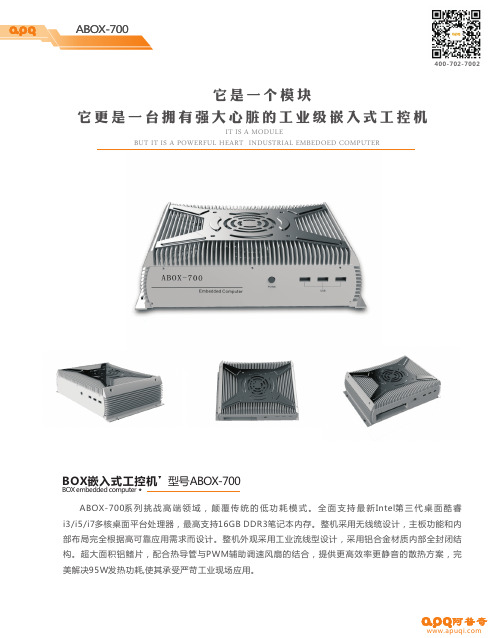
ABOX-700高端领域,颠覆传统的低功耗模式。
全面支持最新Intel 桌面酷睿i3/i5/i7多核桌面平台处理器,最高支持16GB DDR3笔记本内存。
整机采用无线缆设计,主板功能和内部布局完全根据高可靠应用需求而设计。
整机外观采用工业流线型设计,采用铝合金材质内部全封闭结构。
超大面积铝鳍片,配合热导管与PWM 辅助调速风扇的结合,提供更高效率更静音的散热方案,完美解决95W 发热功耗,使其承受严苛工业现场应用。
系列挑战第三代BOX嵌入式工控机型号ABOX-700BOX embedded computer它是一个模块它更是一台拥有强大心脏的工业级嵌入式工控机IT IS A MODULEBUT IT IS A POWERFUL HEART INDUSTRIAL EMBEDOEDCOMPUTER机构参数箱体结构铝型材箱体结构,具有良好的抗震性和抗冲击性表面处理硬质阳极氧化处理,抗刮擦安装方式嵌入式和VESA 壁挂式安装散热系统整机PWM 辅助风扇散热系统电源输入I3 60W/ I5 65W/ I7 95W 最大功耗重量总体尺寸298*205.5*82.5mm (宽高深) 颜色银色内存 最大容量32GB ,DDR3-1066/1333/1600支持网口 2*Intel PCI-E NICS WG82583V for 1000Mbps, 音频 Realtek ALC6625.1 channel HDA Codec,Support MIC/Line-out Ports USB5个端口个具有静USB2.0,4USB2.0/3.0兼容端口8KV 电保护串口 4RS232,2RS232/485选串口,个串口个可GPIO 3输入,3输出通道通道看门狗0~255编程设置秒可选配I /O 口132PCI PCIEx8支持PCIEx1功能1675104527mm 个位或1个插槽(卡,支持扩展卡最大尺寸为:.长*.宽*厚)DC 12V/19V 输入3.5kg RS485端口采用600W 浪涌保护和8KV 静电保护Rj45端口具有防雷,浪涌和15KV 静电保护环境参数工作温度-20℃~60℃存储温度-40℃~80℃相对湿度10~95%@ 40℃振动50~500Hz,1.5g,0.15mm 冲击10g(11ms)操作系统windows xp windows7 windows8 linux工程图(示例图)选型指南:例 ABOX-700-00-I3-4G -500扩展CPU 内存硬盘可选代号:C;L ;P ;E(C 、L 二选一, P 、E 二选一 ,00为不选)C :表示扩展4个RS232串口L :表示扩展4个千兆网口P :表示扩展1个PCI 32bit 插槽E:表示扩展1个PCI-E X8 插槽可选代号:G;I3;I5;I7(以Intel 3代处理器为主)G :表示奔腾双核处理器I3:表示I3双核4线程I5:表示I5四核4线程I7:表示I7四核8线程可选代号:2G ;4G;8G ;16G2G:表示2G DDR3 内存4G :表示4G DDR3 内存8G :表示8G DDR3 内存16G :表示16G DDR3 内存可选代号:500;1TB ;2TB 16G ;32G ;64G ;500:表示500G 机械硬盘1TB :表示1024G 机械硬盘2TB :表示2048G 机械硬盘16G :表示16G 固态硬盘32G :表示32G 固态硬盘64G :表示64G 固态硬盘ABOX-700---- 可选代号:7007:表示7系列嵌入式工控机7系列标准配置CPU :I 系列3代桌面处理器芯片组:B75平台显示: VGA HDMI 多模式双显异显网络:2个 82583v 千兆网卡音频:Realteak HD AudioUSB:4个USB3.0 5个USB2.0内置1个2.0串口:6个RS232(COM1~COM2支持RS485带光电隔离)GPIO :6通道PS/2:键盘接口扩展:1个MINI -PCIE 电源输入:DC12V 或19V。

COR IBR600C SeriesSpec SheetNetCloud Services for IoTCradlepoint COR IBR600C Series IoT routers are sold as part of an all-inclusive IoT networking Cloud IoT Essentials Packages include:—Compact endpoints, purpose-built for IoT and M2M applications—A NetCloud Service Plan tailored for IoT networking and set for a specific term —24x7 support and limited lifetime warrantyWhat to BuyNetCloud IoT Essentials packages and plans contain all the features and capabilities required for a broad range of IoT applications. Essentials Packages include 24x7 support (phone support: 24 hour weekdays with emergency response on weekends, web: 24x7, chat: 24x5) and a limited lifetime warranty.For additional capabilities, a NetCloud IoT Advanced Plan can be added to the NetCloud IoT Essentials Package at any time. See additional details of what is included in the Essential and Advanced NetCloud software: /iot-networksFor more details on the COR IBR600C IoT router, included with the NetCloud IoT Packages, see below.NetCloud Packages and PlansNorth America: U.S. & CanadaNetCloud IoT Essentials and Advanced Plans with IBR600C-150M-D NetCloud IoT Essentials and Advanced Plans with IBR650C-150M-D TBAy-600C150M-NN TBAy-650C150M-NN NetCloud IoT Essentials Plan with IBR600C-150M-D NetCloud IoT Essentials Plan with IBR650C-150M-DTBy-600C150M-NNN TBy-650C150M-N0N Worldwide:European Union (EU) & United Kingdom (UK)NetCloud IoT Essentials and Advanced Plans with IBR600C-150M-B NetCloud IoT Essentials Plan with IBR600C-150M-BTBAy-600C150M-EM TBy-600C150M-EWM Australia & New ZealandNetCloud IoT Essentials and Advanced Plans with IBR600C-150M-B NetCloud IoT Essentials Plan with IBR600C-150M-B TBAy-600C150M-PM TBy-600C150M-PWM All Regions:NetCloud IoT Advanced Plan (Requires an Essentials Plan) Renewal NetCloud IoT Essentials Plan Renewal NetCloud IoT Advanced PlanRenewal NetCloud IoT Essentials and Advanced PlansTBx-NCADV TAx-NCESS-R TBx-NCADV-R TBAx-NCEA-Rx = 1, 3, or 5 years y = 3 or 5 yearsWhat’s in the Box—Ruggedized IBR600C series router with an embedded, enterprise-class LTE modem; includes integrated mounting plate —Two (2) External LTE antennas (SMA)—Two (2) WiFi antennas (RP-SMA) for IBR600C only—12V / 2A power supply w/ locking connector—Two (2) Extra SIM door screws—Safety, Regulatory, and Warranty guideKey FeaturesWAN—Dual-modem capable with optional COR Extensibility Dock—150M-B: 150/50 Mbps DL/UL FDD LTE w/HSPA+ fallback for EU—150M-C: 150/50 Mbps DL/UL FDD LTE w/HSPA+ fallback for APAC—150M-D: 150/50 Mbps DL/UL FDD LTE w/HSPA+ fallback for North America (USA/Canada)—WiFi-as-WAN¹, with WPA2 Enterprise Authentication for WiFi-as-WAN—Failover/Failback—Load Balancing—Advanced Modem Failure Check—WAN Port Speed Control—WAN/LAN Affinity—IP Passthrough—StandbyLAN—VLAN 802.1Q—DHCP Server, Client, Relay—DNS and DNS Proxy—DynDNS—DMZ—Multicast/Multicast Proxy—QoS (DSCP and Priority Queuing)—MAC Address FilteringWiFi1—802.11 b/g/n—Up to 64 connected devices—Multiple SSIDs—WPA2 Enterprise (WiFi)—Hotspot/Captive Portal—SSID-based Priority—Client Mode for faster data offloadManagement—Cradlepoint NetCloud Manager—Web UI, API, CLI—Data Usage Alerts (router and per client)—Advanced Troubleshooting (support)—Device Alerts—SNMP—SMS control—Serial Redirector—Auto APN Recovery—SyslogVPN & Routing—IPsec Tunnel – up to five concurrent sessions—L2TP—GRE Tunnel—OSPF/BGP/RIP—Route Filters (Access Control Lists, Prefix Filters, Route Maps, Communities for BGP)—Per-Interface Routing—Routing Rules—Policy-based Routing—NAT-less Routing—Virtual Server/Port Forwarding—NEMO/DMNR—IPv6—VTI Tunnel support—OpenVPN support—CP Secure VPN compatibleSecurity—RADIUS and TACACS+ support*—802.1x authentication for Ethernet—Zscaler integration—Certificate support—ALGs—MAC Address Filtering—Advanced Security Mode (local user management only)—Per-Client Web Filtering—IP Filtering—Content Filtering (basic)—Website Filtering—Zone-Based Object Firewall with host address (IP or FQDN), port, and MAC address*-Native support for authentication. Authorization and accounting support through hotspot/captive portal services.Cloud Optimized IP Communications—Automated WAN Failover/Failback support—WAN Affinity and QoS allow prioritization of VoIP services—Advanced VPN connectivity options to HQ—SIP ALG and NAT to allow VoIP and UC communications to traverse firewall—802.1p/q for LAN QoS segmentation and treatment of VoIP on LAN—Private Network support (wired and 4G WAN)—Cloud-based managementIoT Connector—NetCloud Edge Connector for Microsoft® Azure IoT Central1 – WiFi-related functions are only supported on IBR600C-XXX models (no WiFi on IBR650C-XXX models)SpecificationsThe following features are delivered through the hardware.WAN:—Dual-modem capable with optional COR Extensibility Dock—Embedded 150M-B, 150M-C, or 150M-D modem—Two LAN/WAN switchable Ethernet ports (one 10/100/1000 and one 10/100) – one default WAN—WiFi-as-WAN, Metro WiFi; 2×2 MIMO “N” 2.4 GHz; 802.11 b/g/n (IBR600C only)LAN:—2×2 MIMO “N” 2.4 GHz WiFi; 802.11 b/g/n (IBR600C only)—Two LAN/WAN switchable Ethernet ports (one 10/100/1000 and one 10/100) – one default LAN—Serial console support for Out-of-Band Management of a connected devicePorts:—Power—2-wire GPIO—Add more GPIO ports with optional 9-wire GPIO cable or COR Extensibility Dock (see Accessories section below)—USB 2.0—Two Ethernet LAN/WAN—Two cellular antenna connectors (SMA)—Two WiFi antenna connectors (R-SMA; IBR600C only)—One GPS connector (SMA) (150M-B, 150M-C, 150M-D only. LPE GPS is muxed on LTE)—15-pin dock port for COR Extensibiliity Dock or 9-wire GPIO cableTemperature: -20 °C to 60 °C (-4 °F to 140 °F) operatingHumidity (non-condensing):—5% to 95% operating—5% to 95% storagePower:—DC input steady state voltage range: 9–33 VDC (requires inline fuse for vehicle installations)—For 9–24 VDC installations, use a 3 A fuse—For > 24 VDC installations, use a 2.5 A fuse—Reverse polarity and transient voltage protection per ISO 7637-2—Ignition sensing (automatic ON and time-delay OFF)—Power consumption:—Idle: 4 W—WiFi Tx/Rx: 9 W—LTE Tx/Tx: 6.25 WWIFI POWER (FCC):2.4 GHz band: 28.1 dBm conductedWIFI POWER (Europe/Rest of World):— 2.4 GHz band: 15 dBm conducted— 2.4 GHz band: 20 dBm EIRPSIZE: 4.6 × 4.5 × 1.2 in (118 × 113.5 × 29.3 mm) WEIGHT: 14 oz (400 g)CERTIFICATIONS:—Regulatory: FCC, IC, CE, RCM (Austrailia/New Zealand), ICASA (South Africa)—WiFi Alliance (IBR600C only) – 802.11 b/g/n certified —Safety: UL/CUL, CB Scheme, EN60950-1—Shock/Vibration/Humidity: compliant with MIL STD 810G and SAEJ1455—Materials: WEEE, RoHS, RoHS-2, California Prop 65—Telecom: PTCRB/CTIAAccessoriesCradlepoint offers several accessory options for extensibility, power, and antennas:EXTENSIBILITY:—COR Extensibility Dock (Part # 170700-000) with compatible MC400 modular modem—MC400-1200M-B (Part # MA-MC400-1200M-B)—MC400-1200M (Part # MA-MC400-1200M)—MC400-600M-C-AT (Part # MC400-C-AT)—MC400LP6 (Part # MC400LP6)—MC400LP4 (Part # MC400LP4)—9-wire power & GPIO cable (Part #170680-000)POWER:Vehicle options—Vehicle locking power adapter for COR (Part # 170635-000)—Two-meter locking power and GPIO cable (direct wire) (Part # 170585-000)Power Supplies/Adapters—North America: COR IBR6x0C power supply (Part # 170716-000)—WARNING: This product (part # 170716-000) can expose you to chemicals including Carbon Black Extracts, which are known to the State of California to cause cancer. For more information go to .—Barrel to 4-pin power adapter (Part # 170665-000)ANTENNAS:See the Cradlepoint Certified Antennas for Fixed Sites for more information about antennas. Also see the Antenna Ordering and Installation Guide, also available in the Resources section of antenna and router product pages.Enterprise-Class Modem SpecificationsCOR IBR600C-150MCOR IBR6X0-150M models include an embedded LTE Category 4 LTE modem. The 150M modems support worldwide SIM-based, auto carrier selection. Simply insert the SIM and wait for the router to automatically detect and establish a connection.COR IBR600C-150M-D-NA; COR IBR650C-150M-D-NA (North America):—Technology: LTE Cat 4 (3GPP Rel 11), DC-HSPA+—Downlink Rates: LTE 150 Mbps, HSPA+ 42.2 Mbps*—Uplink Rates: LTE 50 Mbps, HSPA+ 5.76 Mbps*—Frequency Bands:—LTE: Band 2 (1900 MHz), Band 4 – AWS (1700/2100 MHz), Band 5 (850 MHz), Band 12 (700 MHz), Band 13 (700 MHz), Band 14 (700 MHz), Band 66 – AWS 3 (1700/2100 MHz), Band 71 (600 MHz)—WCDMA/HSPA+/UMTS: Band 2, Band 4, Band 5—Power: LTE 23 dBm ± 1; HSPA+ 23 dBm ± 1; (typical conducted)—Antennas: SMA and RP-SMA male plugs, maximum torque not to exceed 4 in-lbs—GPS/GNSS: Passive, dedicated SMA port (multi-constellation - GPS, GLONASS)—Industry Standards & Certs: FCC, IC, PTCRB, WiFi Alliance (IBR600C only), AT&T, FirstNet Ready™, Verizon, Verizon NEMO/ DMNR for Primary Wireless Access—SIM: Two 2FF slotsCOR IBR600C-150M-B-EU (Europe):—Frequency Bands:—LTE FDD: B1/ B3/ B5/ B7/ B8/ B20—LTE TDD: B38/ B40 /B41—DC-HSPA+/UMTS: B1/ B5/ B8—GSM/EDGE: B3/ B8—Technology: LTE, DC-HSPA+—Downlink Rates: LTE 150 Mbps, HSPA+ 42 Mbps*—Uplink Rates: LTE 50 Mbps, HSPA+ 5.76 Mbps*—Power: LTE 23 dBm ± 2; HSPA+ 23 dBm ± 1; (typical conducted)—Antennas: SMA and RP-SMA male plugs, maximum torque not to exceed 4 in-lbs—GPS: Passive standalone (dedicated SMA port)—Industry Standards & Certs: CE, WiFi Alliance—SIM: Two 2FF slotsCOR IBR600C-150M-C-AU (Australia):—Frequency Bands:—LTE FDD:B1/ B3/ B5/ B7/ B28—DC-HSPA+/UMTS: B1/ B5—Technology: LTE, DC-HSPA+—Downlink Rates: LTE 150 Mbps, HSPA+ 42 Mbps*—Uplink Rates: LTE 50 Mbps, HSPA+ 5.76 Mbps*—Power: LTE 23 dBm ± 2; HSPA+ 23 dBm ± 1; (typical conducted)—Antennas: SMA and RP-SMA male plugs, maximum torque not to exceed 4 in-lbs—GPS: Passive standalone (dedicated SMA port)—Industry Standards & Certs: RCM, WiFi Alliance—SIM: Two 2FF slotsCOR IBR600C-LPE**LPE versions no longer availableCOR IBR600C-LPE/IBR650C-LPE models include an embedded 4G LTE/HSPA+/EVDO modem – specific model names includea specific modem (e.g., the COR IBR650C-LPE-VZ includes a Verizon LTE modem) but is software configurable for Sprint, AT&T,T-Mobile or Canada.COR IBR600C-LPE-AT/GN/SP/VZ; COR IBR650C-LPE-AT/GN/SP/VZ (North America):—Frequency Bands:—LTE: Band 2 (1900 MHz), Band 4 – AWS (1700/2100 MHz), Band 5 (850 MHz), Band 13 (700 MHz), Band 17 (700 MHz), Band 25 (1900 MHz)—HSPA+/UMTS: (850/900/1900/2100 MHz, AWS)—GSM/GPRS/EDGE: (850/900/1800/1900 MHz)—CDMA EVDO: Rev A/1xRTT (800/1900 MHz)—Technology: LTE, HSPA+, EVDO Rev A—Downlink Rates: LTE 100 Mbps, HSPA+ 21.1 Mbps, EVDO 3.1 Mbps*—Uplink Rates: LTE 50 Mbps, HSPA+ 5.76 Mbps, EVDO 1.8 Mbps*—Power: LTE 23 dBm ± 1; HSPA+ 23 dBm ± 1; EVDO 24 dBm ± 1 (typical conducted)—Antennas: SMA and RP-SMA male plugs, maximum torque not to exceed 4 in-lbs—GPS: Passive, muxed on aux port—Industry Standards & Certs: FCC, WiFi Alliance (IBR600C only), AT&T, Sprint, Verizon, Verizon NEMO/DMNR for Primary Wireless Access—SIM: Two 2FF slots*Theoretical SpeedsHardwareIBR600C-150M3G/4G Antenna Connector (SMA)GPS Connector3G/4G Antenna Connector (SMA)LEDsSIM slots Support & WarrantyThe COR IBR600C series are only sold as a components of NetCloud Packages. —NetCloud Packages include support for the full subscription term.—All Cradlepoint hardware products are covered by a limited lifetime warranty for as long as they have a subscription license to anactive NetCloud Service Plan.FirstNet and FirstNet Ready are registered trademarks and service marks of the First Responder Network Authority, an independent authority within the U.S. Department of Commerce.Power/GPIO ConnectorThis connector has four pin slots: power, ground, input, and output.Connector pinout – view into router (rear view of cable connector):Reset Button WiFi Antenna Connector (Reverse SMA)USB 2.0 Port 10/100 Ethernet Port (Configurable: LAN or WAN Default: WAN)10/100/1000 Ethernet Port (Configurable: LAN or WAN Default: LAN)Power Port WiFi Antenna Connector (Reverse SMA)Router to Dock ConnectorIBR600C-LPE 3G/4G Antenna Connector (SMA)3G/4G Antenna Connector (SMA)LEDs SIM slotsLEDs。
用户手册ARK-1124无风扇嵌入式工控机版权声明随附本产品发行的文件为研华公司2017年版权所有,并保留相关权利。
针对本手册中相关产品的说明,研华公司保留随时变更的权利,恕不另行通知。
未经研华公司书面许可,本手册所有内容不得通过任何途径以任何形式复制、翻印、翻译或者传输。
本手册以提供正确、可靠的信息为出发点。
但是研华公司对于本手册的使用结果,或者因使用本手册而导致其它第三方的权益受损,概不负责。
认可声明Award为Award Software International, Inc.的商标。
VIA为VIA Technologies, Inc.的商标。
IBM、PC/AT、PS/2和VGA为International Business Machines Corporation的商标。
Intel和Pentium为Intel Corporation的商标。
Microsoft Windows®为Microsoft Corp.的注册商标。
RTL为Realtek Semi-Conductor Co., Ltd.的商标。
ESS为ESS Technology, Inc.的商标。
UMC为United Microelectronics Corporation的商标。
SMI为Silicon Motion, Inc.的商标。
Creative为Creative Technology LTD.的商标。
CHRONTEL为Chrontel Inc.的商标。
所有其它产品名或商标均为各自所属方的财产。
如需本产品或研华其它产品的更多信息,请访问://ePlatform/如需技术支持与服务,请访问我们的技术支持网站:/support/产品质量保证(两年)从购买之日起,研华为原购买商提供两年的产品质量保证。
但对那些未经授权的维修人员维修过的产品不予提供质量保证。
研华对于不正确的使用、灾难、错误安装产生的问题有免责权利。
如果研华产品出现故障,在质保期内我们提供免费维修或更换服务。
GeneralEaton meets the full requirements of IEEE Std386™-2006 standard—Separable Insulated Connector Systems, with its Cooper Power™ series 600 A, 35 kV insulated standoff bushing providing a single deadbreak interface made of high quality insulating epoxy material. It is used in pad-mounted cabinets, underground vaults, and other apparatus to isolate and sectionalize an energized cable.Temporary or permanent parking of energized 600 A 35 kV deadbreak connectors that conform to IEEE Std 386™-2006 standard is simplified with the use of insulated standoff bushings.The insulated standoff bushing is designed to be installed in the parking stand mounted on a transformer or other apparatus. A drain wire lug is provided on the standoff bracket for attachment of a drain wire to ensure deadfront construction. The bushing provides a fully-shielded, submersible connection for deadbreak operation.Eaton's Cooper Power series 600 A, 35 kV grounded standoff bushing is designed to beinstalled in the parking stand bracket mounted on the transformer or other apparatus.A 2/0 AWG copper, 5-foot jacketed cable isconnected to the all-aluminum bushing for attach-ment to system ground. The bushing provides a fully visible ground and submersible connection for temporary or permanent parking of 600 A deadbreak connectors that conform to IEEE Std 386™-2006 standard.All standoff bushing brackets have a stainless steel eyebolt with a brass pressure foot. The bushing body is bolted to a stainless steel base bracket using a stainless steel bolt. Special pins ensure firm location of the bushing on the bracket.InstallationA clampstick tool is used to place the standoff bushing in the parking stand on the front plate of the apparatus. Special tools are required to thread de-energized 600 A connectors onto the standoff bushing. Refer to the appropriate connectorcatalog section or installation instruction for further clarification. Refer to Service Information S600-24-1 15, 25, and 35 kV Class Insulated Standoff Bushing Installation Instructions for complete installation details on the insulated standoffbushing. For installation of the grounded standoff bushing, refer to Service Information S600-24-2 15, 25, and 35 kV Class Grounded Standoff Bushing Installation Instructions for details.600 A 35 kV class standoff bushingsProduction tests (insulated standoff bushing)Tests conducted in accordance with IEEE Std 386™-2006 standard:•ac 60 Hz 1 Minute Withstand • 50 kV•Minimum Corona Voltage Level • 26 kVTests conducted in accordance with Eaton requirements:• Physical Inspection • Periodic Dissection•Periodic Fluoroscopic AnalysisFigure 1. Grounded standoff bushing on left is made of aluminum alloy and has five feet of insulated cable. Insulated bushing on right is molded of epoxy insulation material.otee:N Dimensions given are for reference only.BRACKETStainless steel mounting bracket has drain wire lug for bracket and shield grounding.COPPER CABLE 60" (1.52 mm) 2/0Flexible, all weather 600 V insulated copper cableprovides ease of handling and ensures positive grounding.STANDARD 5/8"— 11 UNC 2BTHREADS meet IEEE Std 386™-2006standard pecifications for 600 A apparatus.EPOXY INSULATIONHigh quality molded epoxy insulation providesexcellent electrical, thermal and mechanical reliability for insulated standoff bushings. (Grounded standoff bushings are made of solid wrought aluminum alloy).BRACKET Stainless steel mounting bracket has drain wire lug for bracket and shield grounding.EYEBOLTStainless steel eyebolt with brass pressure foot rig-idly secures standoff bushing to parking stand.DRAIN WIRE LUG Provides apparatus for attaching drain wire.5.6"(142 mm)S84.4"(112 mm)5.4"(137 mm)ALUMINUM5.6"(142 mm)4.4"(112 mm)5.4"(137 mm)S8Figure 2. Standoff bushing stacking dimensions.TANK WALL35 kVGroundedInsulatedS70.75" (19 mm)0.75" (19 mm)S85.7" (145 mm)5.2" (132 mm)S8S7T able 2. Current Ratings and Characteristics —Grounded Standoff BushingDescriptionAmperesShort Time 25,000 A rms symmetrical for 0.17sT able 1. Voltage Ratings and Characteristics —Insulated Standoff BushingDescriptionkVStandard Voltage Class35Maximum Rating Phase-to-Ground 21.1ac 60 Hz 1 Minute Withstand 50dc 15 Minute Withstand 103BIL and Full Wave Crest 150Minimum Corona Voltage Level26Voltage ratings and characteristics are in accordance with IEEE Std 386™-2006 standard.Current ratings and characteristics are in accordance with IEEE Std 386™-2006 standard.2Catalog Data CA650057ENEffective May 2015600 A 35 kV class standoff bushings/cooperpowerseries3Catalog Data CA650057ENEffective May 2015600 A 35 kV class standoff bushings /cooperpowerseries600 A 35 kV class standoff bushings Catalog Data CA650057ENEffective May 2015Eaton1000 Eaton BoulevardCleveland, OH 44122United StatesEaton’s Cooper Power Systems Division2300 Badger DriveWaukesha, WI 53188United States/cooperpowerseries© 2015 EatonAll Rights Reserved Printed in USA Publication No. CA650057ENFor Eaton's Cooper Power series standoffbushings product informationcall 1-877-277-4636 or visit:/cooperpowerseries. Eaton, Cooper Power, and T-OP are valuabletrademarks of Eaton in the U.S. and othercountries. Y ou are not permitted to use thesetrademarks without the prior written consentof Eaton.IEEE Std 386™-2006 standard are trademarksof the Institute of Electrical and ElectronicsEngineers, Inc., (IEEE). This publication is notendorsed or approved by the IEEE.。
ABOX-500/600嵌入式计算机用户手册成都阿普奇科技股份有限公司在使用本产品之前,请务必先仔细阅读本使用手册。
编号: APQ8.830.196 请务必妥善保管好本手册,以便日后能随时查阅(保留备用)。
版本号: A/0随附本产品发布的文件为阿普奇科技股份有限公司2014年版权所有,并保留相关权利。
针对本手册中相关产品说明,阿普奇科技股份有限公司保留随时变更的权利,恕不另行通知。
未经阿普奇科技股份有限公司书面许可,本手册所有内容不得通过任何途径以任何形式复制、翻译、翻印、修改、转载或者传输。
本手册以提供正确、可靠的信息为出发点。
但是阿普奇科技股份有限公司对于本手册的使用结果,或者因使用本手册而导致其它协力厂商的权益受损,概不负责。
AMI 为American Megatrends, Inc. 的注册商标。
Intel 和Atom 为Intel Corporation 的商标。
VGA 为International Business Machines Corporation 的商标。
Intel 和Atom 为Intel Corporation的商标。
Microsoft Windows 为Microsoft Corp. 的注册商标。
RTL 为Realtek Semiconductor Co., Ltd. 的商标。
所有其他产品名称和商标均为其所有者的财产。
有关本产品及成都阿普奇科技股份有限公司其它产品的信息,请访问我们的网站:本手册适用于ABOX-500/600嵌入式计算机这些限制只为商业环境下的系统操作提供合理保护,使其免受有害干扰。
本设备会产生使用和发射无线电频率能量。
如果没有按照手册说明正确安装和使用,可能对无线电通讯造成有害干扰。
但即使按照手册说明进行安装和使用,也并不能保证不会产生干扰。
若本设备会对无线电或电视信号接收产生有害干扰,用户可通过开、关设备进行确认。
当本设备产生有害干扰时,用户可采取下面的措施来解决干扰问题:2、 增大本设备与接收器之间的距离3、 将本设备的电源接头插在与接收器使用不同电路的电源插座4、 若需技术支持,请咨询经销商或经验丰富的无线电/电视技术人员警告!若未经相关权威机构明确批准而擅自更改或修理设备,则用户操作本设备的权利可能会被取消。
在您打开包装箱时,请确认包装箱中物品:嵌入式计算机 ABOX-500/600 1 台 国标电源线 1.5M 三芯 1 条驱动光盘 1 张 安装支架 APQ7.037.472 (安装在主机上 )2 个电阻笔 合格证 1 份如有缺失,请立即与经销商或销售代表联系。
名称 型号 数量用户手册 ABOX-500/600(驱动光盘内) 1 份 电源适配器 4芯带锁 1 个 凤凰头子 15ELZK-3.5mm-10P 绿色 1 个 保修卡 1 份装箱清单 1 份例:ABOX-600-00-J9-4G-500- - - -例:ABOX-500-00-J8-2G-32G- - - -ABOX-600 扩展 CPU 内存 硬盘可选代号:6006:表示600系列嵌入式电脑 600系列标准配置CPU:凌动4代J1900主频2.0GHz 芯片组:SoC显示:VGA HDMI 多模式双显 网络:2个RTL8111E 千兆网口 音频:Realtek HD Audio USB:1个 USB3.0 7个USB2.0 串口:6个RS232(COM1/2支持RS485带光电隔离) GPIO:8通道扩展:1个Mini PCIE 与Mini SATA可选代号:C;K(00为不选)C:表示扩展4个RS232 串口K:表示宽压电源DC 8~30V输入(选用K时,主机的Mini PCIE 无法使用)注:C 与K 不能同时使用可选代号:J9凌动4代J1900处理器 规模参数 主频:2GHz 睿频:2.41GHz 二级缓存:2M 功耗:10W 四核四线程可选代号:2G;4G;8G2G:表示2G DDR3内存 4G:表示4G DDR3内存 8G:表示8G DDR3内存可选代号:500; 1TB; 2TB; 16G;32G;64G ;128G;256G; 500:表示500G 机械硬盘 1TB:表示1024G 机械硬盘 2TB:表示2048G 机械硬盘 16G:表示16G 固态硬盘 32G:表示32G 固态硬盘 64G:表示64G 固态硬盘 128G:表示128G 固态硬盘 256G:表示256G 固态硬盘ABOX-500 扩展 CPU 内存 硬盘可选代号:5005:表示500系列嵌入式电脑 500系列标准配置CPU:凌动4代J1800主频2.41GHz 芯片组:SoC显示:VGA HDMI 多模式双显网络:2个RTL8111E 千兆网口 音频:Realtek HD AudioUSB:1个 USB3.0 7个USB2.0串口:6个RS232(COM1/2支持RS485带光电隔离)GPIO:8通道扩展:1个Mini PCIE与Mini SATA 可选代号:C;K(00为不选)C:表示扩展4个RS232 串口K:表示宽压电源DC 8~30V输入(选用K时,主机的Mini PCIE 无法使用)注:C 与K 不能同时使用可选代号:J8凌动4代J1800处理器规模参数主频:2.41GHz睿频:2.58GHz二级缓存:1M功耗:10W 双核双线程可选代号:2G;4G;8G2G:表示2G DDR3内存 4G:表示4G DDR3内存 8G:表示8G DDR3内存可选代号:500; 1TB; 2TB; 16G;32G;64G ;128G;256G; 500:表示500G 机械硬盘 1TB:表示1024G 机械硬盘 2TB:表示2048G 机械硬盘 16G:表示16G 固态硬盘 32G:表示32G 固态硬盘 64G:表示64G 固态硬盘 128G:表示128G 固态硬盘 256G:表示256G 固态硬盘1、有关该系列产品的最新信息,请访问阿普奇科技股份有限公司的网站:2、用户若需技术支持,请与当地分销商、销售代表或阿普奇科技股份有限公司客服中心联系,进行技术咨询。
3、进行技术咨询前,用户须将下面各项产品信息收集完整:产品名称、型号及序列号外围附加设备的描述用户软件的描述(操作系统、版本、应用软件等)每条错误信息的完整内容产品所出现问题的完整描述警告!1、整机输入电压为DC12V2、包装箱里取出产品时需谨慎,请以双手托住产品3、请使用认可的产品或以干燥的物品,正确的对产品进行清洁1、请仔细阅读此安全操作说明。
2、请妥善保存好此用户手册,以便日后参考。
3、对于使用电源线的设备,设备周围必须有容易接触到的电源插座。
4、当您连接设备到电源插座上时,请确认电源插座的电压是否符合要求。
5、请将电源线布置在人们不易绊到的位置,并不要在电源线上覆盖任何杂物。
6、清洁设备前,请从插座拔下电源线。
请不要使用液体或去污喷雾剂直接清洁设备,应借助抹布使用。
7、请在安装前确保设备放置在可靠的平面上,防止意外跌落。
8、如果长时间不使用设备,请将其同电源插座断开,避免设备被超标的电压波动损坏。
9、请不要把设备存储在超出我们建议的温度范围的环境。
即不要低于-40℃或高于80℃否则可能会损坏设备。
1O、请不要让任何液体流入设备,以免引起短路或者火灾。
11、请不要自行打开设备。
为了确保您的安全,请由专业的技术人员或经过认证的工程师来打开设备。
如遇下列情况,请由专业人员来维修:设备跌落或者损坏;设备内部有液体流入;电源线或插头损坏;设备有明显的外观损坏;设备无法正常工作,或您无法通过用户手册来使其正常工作;第一章概况1.1 产品简介 (8)1.2 产品特点 (8)1.3 产品规格 (9)1.3.1 系统参数 (9)1.3.2 机构和电源 (9)1.3.3 环境参数 (10)1.4 工程图 (10)1.5 简单拆卸与安装 (11)1.5.1 内存或硬盘更换 (11)1.5.2 COM口设置 (13)1.5.3 扩展模块的安装方法 (14)第二章系统安装2.1 入门指南 (16)2.2 接口定义 (17)2.3 安装步骤 (20)2.3.1 连接电源线 (20)2.3.2 正常开机 (20)2.4 BIOS设置 (20)2.5 操作系统安装 (24)2.6 安装驱动 (24)2.6.1 驱动程序 (24)2.6.2 注意事项 (24)第三章有关产品注意事项3.1 使用维护的注意事项 (25)3.2 安装硬件与检修的注意事项 (25)3.3 维修实施注意事项 (25)3.4 常见故障分析及解决措施 (26)3.5 贮存 (26)第一章概况1.1产品简介ABOX-500/600采用Intel Bay Trail平台,Intel Bay Trail平台是迄今为止最佳的“高性能、低功耗”处理器平台,产品家庭专为今天的智能系统所需的性能和功耗均衡而生,Intel Bay Trail平台在计算、媒体及图片处理能力方面,表现出超凡的性能。
ABOX-500/600采用强固、紧凑、防冲击、抗振动工业级设计方案,无风扇散热系统,内部简洁无冗杂接线。
满足工业现场苛刻应用环境。
ABOX-500/600拥有丰富多元化的输入输出接口,包括2个千兆以太网口,7个高速USB2.0与1个USB3.0端口,6个RS232串口(COM1/2支持RS485同时可扩展到10个串口)、1个HDMI接口、VGA显示和音频输入输出接口、1个8路的GPIO等;支持Wifi 或3G Mini PCIE模块;支持2.5寸高速SATA硬盘与Mini SATA硬盘等存储装置,内置LPT插口。
ABOX-500/600兼容windows®7、Windows®8、Android、Embedded Linux等主流操作系统。
1.2产品特点整机采用模块化设计思路,便于系统维修和设备部件更换。
采用Intel Bay Trail平台。
大面铝鳍被动式散热传导装置,整机无风扇设计,内部简洁无冗杂接线,确保嵌入式电脑能在恶劣的环境下不间断工作。
紧凑坚固的铝合金机身使具有良好的抗震和搞冲击性。
配备丰富的多元化的输入输出接口,连接更多所需的设备。
1.3产品规格1.3.1系统参数处理器:Intel® Bay Trail J1800/J1900处理器芯片组:SoC磁盘:SATA 500GB 2.5”HDD,可选SSD内存:4G DDR3 SDRAM,最高可升级至8GB显示:Intel HD Graphics,支持VGA,HDMI显示接口,可双显异显音频:Realtek ALC662 5.1 Channel HDA Codec,Support MIC/Line-out Ports网口:2个RTL8111E千兆RJ45端口,LAN1支持网络唤醒串口:6个RS232(其中COM1/2支持RS485带光电隔离,可扩展到10个串口)U S B :1个USB 3.0,7个USB2.0G P I O :8通道扩展:1个MINI PCI-E内置接口:1个LPT口1.3.2 机构和电源机箱结构 : 铝型材结构,具有良好的抗震性和抗冲击性表面处理: 硬质阳极氧化处理,抗刮擦安装方式 : 固定方式和VESA壁挂式安装颜色 : 银色散热系统 : 整机无风扇设计。