SK32 THRU SK310 SMA
- 格式:pdf
- 大小:385.21 KB
- 文档页数:2
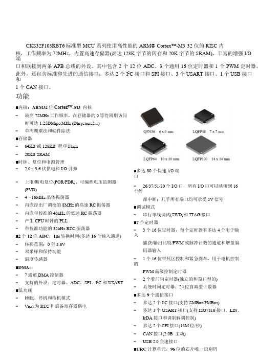
CKS32F103RBT6标准型 MCU 系列使用高性能的 ARM® Cortex™-M3 32 位的 RISC 内核,工作频率为 72MHz,内置高速存储器(高达 128K 字节的闪存和 20K 字节的 SRAM),丰富的增强 I/O端口和联接到两条 APB 总线的外设。
其中包含 2 个 12 位 ADC、3 个通用 16 位定时器和 1 个 PWM 定时器,此外,还包含标准和先进的通信接口:多达 2 个 I2C 接口和 SPI 接口、3 个 USART 接口、1 个 USB 接口和1 个 CAN 接口。
功能■内核:ARM32位Cortex™-M3 内核−最高72MHz工作频率,在存储器的0等待周期访问时可达1.25DMips/MHz (Dhrystone2.1)−单周期乘法和硬件除法■存储器−64KB 或 128KB 程序 Flash−20KB SRAM■时钟、复位和电源管理− 2.0~3.6伏供电和I/O引脚■多达80个快速I/O端口−上电/断电复位(POR/PDR)、可编程电压监测器(PVD)−4~16MHz晶体振荡器−内嵌经出厂调校的8MHz的高速RC振荡器−内嵌带校准的40kHz的低速RC振荡器−产生CPU时钟的PLL−带校准功能的32kHz RTC振荡器■2个12位ADC,1μs转换时间(多达16个输入通道) −转换范围:0至3.6V−双采样和保持功能−温度传感器■DMA:−7通道DMA控制器−支持的外设:定时器、ADC、SPI、I2C和USART ■低功耗−睡眠、停机和待机模式−V BAT为RTC和后备寄存器供电−26/37/51/80个I/O口,所有I/O口可以映像到16个外部中断;几乎所有端口均可承受5V信号■调试模式−串行单线调试(SWD)和JTAG接口■7个定时器−3个16位定时器,每个定时器有多达4个用于输入捕获/输出比较/PWM或脉冲计数的通道和增量编码器输入−1个16位带死区控制和紧急刹车,用于电机控制的PWM高级控制定时器−2个看门狗定时器(独立的和窗口型的)−系统时间定时器:24位自减型计数器■多达9个通信接口−多达2个I2C接口(支持SMBus/PMBus)−多达3个USART接口(支持ISO7816接口,LIN,IrDA接口和调制解调控制)−多达2个SPI接口(18M位/秒)器件对比CKS32F103x8(B)产品功能和外设配置产品型号外围接口CKS32F103C8/CB CKS32F103RB CKS32F103VB 闪存- K 字节64 128 128 128SRAM- K 字节20 20 20定时器通用目的 3 3 3 高级控制 1 1 1 SPI 2 2 2 I2C 2 2 2通信接口USART 3 3 3 USB 1 1 1CAN 1 1 1 GPIO 端口(通道数) 37 51 8012 位同步 ADC 2 2 2(通道数) 10 channels 16 channels 16 channels CPU 频率72 MHz工作电压 2.0V ~3.6V工作温度环境温度:-40℃~ +85℃/-40℃~+105℃结温度:-40℃~+125℃封装LQFP48 LQFP64 LQFP100订购信息托盘装产品型号封装形式盘装数盒装盘盒装数箱装盒箱装数CKS32F103C8T6 LQFP48 250PCS/盘10 盘/盒2500PCS/盒 6 盒/箱15000PCS/箱CKS32F103CBT6 LQFP48 250 PCS/盘10 盘/盒2500PCS/盒 6 盒/箱15000 PCS/箱CKS32F103RBT6 LQFP64 160 PCS/盘10 盘/盒1600 PCS/盒 6 盒/箱9600 PCS/箱CKS32F103VBT6 LQFP100 90 PCS/盘10 盘/盒900 PCS/盒 6 盒/箱5400 PCS/箱目录1.介绍 (1)2. 规格说明 (2)2.1 概述 (2)2.1.1 ARM®的Cortex™-M3 核心并内嵌闪存和 SRAM (2)2.1.2 内置闪存存储器 (2)2.1.3 CRC(循环冗余校验)计算单元 (3)2.1.4 内置 SRAM (3)2.1.5 嵌套的向量式中断控制器(NVIC) (3)2.1.6 外部中断/事件控制器(EXTI) (3)2.1.7 时钟和启动 (3)2.1.8 自举模式 (4)2.1.9 供电方案 (4)2.1.10 供电监控器 (4)2.1.11 调压器 (4)2.1.12 低功耗模式 (5)2.1.13 DMA (5)2.1.14 RTC(实时时钟)和后备寄存器 (5)2.1.15 定时器和看门狗 (6)2.1.16 I2C 总线 (7)2.1.17 通用同步/异步收发器(USART) (7)2.1.18 串行外设接口(SPI) (7)2.1.19 控制器区域网络(CAN) (8)2.1.20 通用串行总线(USB) (8)2.1.21 通用输入输出接口(GPIO) (8)2.1.22 ADC(模拟/数字转换器) (8)2.1.23 温度传感器 (9)2.1.24 串行单线 JTAG 调试口(SWJ-DP) (9)3. 引脚定义 (12)4. 存储器映像 (20)5. 电气特性 (21)5.1.1 最小和最大数值 (21)5.1.2 典型数值 (21)5.1.3 典型曲线 (21)5.1.4 负载电容 (21)5.1.5 引脚输入电压 (22)5.1.6 供电方案 (23)5.1.7 电流消耗测量 (23)5.2 绝对最大额定值 (24)5.3 工作条件 (25)5.3.1 通用工作条件 (25)5.3.2 上电和掉电时的工作条件 (25)5.3.3 内嵌复位和电源控制模块特性 (26)5.3.4 内置的参照电压 (27)5.3.5 供电电流特性 (27)5.3.6 外部时钟源特性 (31)5.3.7 内部时钟源特性 (35)5.3.8 PLL 特性 (36)5.3.9 储存器特性 (36)5.3.10 EMC 特性 (37)5.3.11 绝对最大值(电气敏感性) (38)5.3.12 I/O 端口特性 (39)5.3.13 NRST 引脚特性 (42)5.3.14 TIM 定时器特性 (43)5.3.15 通信接口 (43)5.3.16 CAN(控制器局域网络)接口 (48)5.3.17 12 位 ADC 特性 (48)5.3.18 温度传感器特性 (52)6. 封装特性 (53)6.1 封装机械数据 (53)6.2 热特性 (57)7. 型号命名 (58)8. 版本历史 (59)1.介绍本文给出了 CKS32F103x8 和 CKS32F103xB 标准型 MCU 产品的器件特性。

May 201622-1925-1A-ENSplit System Heat Pump 3–Phase4TWA7036A3000A 4TWA7048A3000A 4TWA7060A3000A 4TWA7036A4000A 4TWA7048A4000A4TWA7060A4000AN o t e :“Graphics in this document are for representationonly.Actual model may differ in appearance.”T able of ContentsProduct Specifications (3)Sound Power Level (5)Accessory Description and Usage (6)Model Nomenclature (6)SCHEMATIC (7)Outline Drawing (9)Mechanical Specification Options (10)Product Specifications(a)Certified in accordance with the Air-Source Unitary Air-conditioner Equipment certification program,which is based on AHRI standard210/240.(b)Rated in accordance with AHRI standard270.(c)Calculated in accordance with N.E.C.Only use HACR circuit breakers or fuses.(d)This value shown for compressor RLA on the unit nameplate and on this specification sheet is used to compute minimum branch circuit ampacity and max.fuse size.The value shown is the branch circuit selection current.(e)This value approximate.For more precise value see unit nameplate.(f)Reference the outdoor unit ship-with literature for refrigerant piping length and lift guidelines.Reference the refrigerant piping software pub#32-3312-xx or refrigerant piping application guide SS-APG006-xx for long line sets or specialty applications(xx denotes latest revision).(g)Trane outdoor condensing units are factory charged with the system charge required for the outdoor condensing unit and15feet of tested connectinglines.If connecting line length exceeds15feet,then final refrigerant charge adjustment is necessary.Each additional foot over15feet requires0.6ozs of refrigerant.See the Installer’s Guide for full charging instructions.(h)This value approximate.For more precise value see unit nameplate.(i)*=15,20,25,30,40and50foot lineset available.P r o d u c t S p e c i f i c a t i o n s(a)Certified in accordance with the Air-Source Unitary Air-conditioner Equipment certification program,which is based on AHRI standard210/240.(b)Rated in accordance with AHRI standard270.(c)Calculated in accordance with N.E.C.Only use HACR circuit breakers or fuses.(d)This value shown for compressor RLA on the unit nameplate and on this specification sheet is used to compute minimum branch circuit ampacity and max.fuse size.The value shown is the branch circuit selection current.(e)This value approximate.For more precise value see unit nameplate.(f)Reference the outdoor unit ship-with literature for refrigerant piping length and lift guidelines.Reference the refrigerant piping software pub#32-3312-xx or refrigerant piping application guide SS-APG006-xx for long line sets or specialty applications(xx denotes latest revision).(g)Trane outdoor condensing units are factory charged with the system charge required for the outdoor condensing unit and15feet of tested connectinglines.If connecting line length exceeds15feet,then final refrigerant charge adjustment is necessary.Each additional foot over15feet requires0.6ozs of refrigerant.See the Installer’s Guide for full charging instructions.(h)This value approximate.For more precise value see unit nameplate.(i)*=15,20,25,30,40and50foot lineset available.Sound Power LevelAccessory Description and UsageA n t i-S h o r t C y c l e T i m e r—Solid state timing device that prevents compressor recycling untilfive(5)minutes have elapsed after satisfying call or power e in area withquestionable power delivery,commercial applications,long lineset,etc.E v a p o r a t i o n D e f r o s t C o n t r o l—SPST Temperature actuated switch that cycles the condenseroff as indoor coil reaches freeze-up ed for low ambient cooling to30°F with TXV.R u b b e r I s o l a t o r s—Five(5)large rubber donuts to isolate condensing unit from transmittingenergy into mounting frame or e on any application where sound transmission needs tobe minimized.H a r d S t a r t K i t—Start capacitor and relay to assist compressor motor e in areas withmarginal power supply,on long linesets,low ambient conditions,etc.E x t r e m e C o n d i t i o n M o u n t K i t—Bracket kits to securely mount condensing unit to a frame orpad without removing any e in areas with high winds,or on commercial roof tops,etc.A H R I S t a n d a r d C a p a c i t y R a t i n g C o n d i t i o n sAHRI Standard210/240Rating Conditions1.Cooling80°F DB,67°F WB air entering indoor coil,95°F DB air entering outdoor coil.2.High Temperature Heating47°F DB,43°F WB air entering outdoor coil,70°F DB air enteringindoor coil.3.Low Temperature Heating17°F DB air entering indoor coil.4.Rated indoor airflow for heating is the same as for cooling.A H R I S t a n d a r d270R a t i n g C o n d i t i o n s—(Noise rating numbers are determiend with the unit incooling operations.)Standard Noise Rating number is at95°F outdoor air.Model NomenclatureSCHEMATIC230V HP—D159297P02460V HP —D159194P02S C H E M A T I COutline DrawingMechanical Specification OptionsG e n e r a lThe Outdoor Units are fully charged from the factory for up to15feet of piping.This unit isdesigned to operate at outdoor ambient temperatures as high as115°F.Cooling capacities arematched with a wide selection of air handlers and furnace coils that are AHRI certified.The unit iscertified to UL1995.Exterior is designed for outdoor application.C a s i n gUnit casing is constructed of heavy gauge,galvanized steel and painted with a weather-resistantpowder paint finish on all louvered panels and the fan top panel.The corner panels areprepainted.All panels are subjected to our1,000hour salt spray test.The base is made of aCMBP-G30weatherproof material to resist corrosion.R e f r i g e r a n t C o n t r o l sRefrigeration system controls include condenser fan,compressor contactor and high pressureswitch.High and low pressure controls are inherent to the compressor.A factory supplied liquidline drier is standard.Some models may require field installation.C o m p r e s s o rThe compressor features internal over temperature,pressure protection and total dippedhermetic motor.Other features include:Centrifugal oil pump and low vibration and noise.C o n d e n s e r C o i lThe outdoor coil provides low airflow resistance and efficient heat transfer.The coil is protectedon all four sides by louvered panels.L o w A m b i e n t C o o l i n gAs manufactured,this system has a cooling capacity to55°F.The addition of an evaporatordefrost control permits operation to40°F.The addition of an evaporator defrost control with TXVpermits low ambient cooling to30°F.T h e r m o s t a t s—Cooling only and heat/cooling(manual and automatic change over).Sub-base tomatch thermostat and locking thermostat cover.E v a p o r a t o r D e f r o s t C o n t r o l—See Low Ambient Cooling.N o t e s 22-1925-1A-EN11Trane optimizes the performance of homes and buildings around the world.A business of Ingersoll Rand,the leader in creating and sustaining safe,comfortable and energy efficient environments,Trane offers a broad portfolio of advanced controls and HVAC systems,comprehensive building services,and parts.For more information,visit .Trane has a policy of continuous product and product data improvements and reserves the right to change design and specifications without notice.©2016Trane22-1925-1A-EN17May2016Supersedes(New)。

一块高端工业控制终端好选择 —— SK-AM64评估套件测评近几年嵌入式最火的领域,各种工控网关终端绝对算得上一个。
智能家电和工控设备更新换代,对控制终端提出了越来越多的要求,各老牌大厂都不断在更新自己的方案。
目前对这个领域的方案主要需求是更高的安全性、更高的集成度、更高的稳定性、更强的性能,但是开发者如何选择一款合适的方案并非易事。
德州仪器(TI)新推出的AM64X系列方案绝对是目前此领域非常不错的的代表,这次就由我带大家了解一下基于AM64x处理器的评估套件SK-AM64。
开箱视频一、开箱SK-AM64评估套件使用纸质外盒包装,包装盒正面印着产品型号,背面是评估板板载资源的列表和简单的使用说明。
打开盒子可以看到由防静电袋装着开发板。
AM64x 入门套件是一个完整测试和开发平台,适合用于加速原型设计。
套件包括:有线和无线连接、三个扩展头、多个引导选项和灵活的调试功能。
配有TI 的AM64x 处理器和优化的功能集,允许用户使用基于以太网的接口、USB 接口、有线串行接口以及2.4GHz 和5GHz 无线通信来创建商业和工业解决方案。
两个板载1Gbps 以太网端口用于有线连接,此外还有三个扩展头用于扩展板功能。
此套件采用标准串行协议(如UART、I²C 和SPI),可用作通信网关与多个其他器件进行连接。
该入门套件可通过在A53 内核上运行Linux 进行评估,从而可作为远程工业通信网络中的中央引擎,也适合用作可编程逻辑控制器或运动控制器。
额外的嵌入式仿真逻辑允许使用标准开发工具(例如TI 的Code Composer Studio™)进行仿真和调试。
特性•软件:TI Processor SDK Linux/RT Linux/RTOS内核、Yocto文件系统、包含Wi-Fi® 的开箱即用例程•处理:AM64x,含2 个Arm Cortex-A53、4 个Arm Cortex-R5F、1个可以做安全功能使用的M4F,2 个PRU_ICSSG•通过 WiLink™8 WL1837MOD 模块实现双频带Wi-Fi®、Bluetooth®/低功耗蓝牙 5.1;2 个1000/100Mbps RJ-45 以太网接口•连接:可通过micro-USB 连接1 个Type A USB 3.1 gen1(超高速)、板载XDS110 JTAG 仿真器和 3 个UART•扩展和原型设计:40 引脚Raspberry Pi (RPI4) HAT、PRU-ICSSG 实时I/O 和TI-MCU 头•存储: 2GB LPDDR4;SK 上的可引导接口:可移除uSD、USB、16MB OSPI、以太网、UART开发需要自配的硬件•USB-C 5V 3A 电源•USB SD 卡写入器•Micro-SD 卡(16GB 或更大)•用于UART 串行通信的USB Micro-B 电缆•以太网电缆(可选)二、硬件描述此评估板集成了丰富的扩展接口,并且都是目前最流行的扩展接口,比如集成了兼容Raspberry Pi的扩展接口,这将能适配目前Raspberry Pi种类丰富的第三方外设模块,这将简化原型设计的难度而且更具可玩性,让开发者快速验证自己的创意。


Main UnitModel No.Global Code AGP3200-A1-D24PFXGP3200AAD AGP3200-T1-D24PFXGP3200TAD AGP3200-T1-D24-M PFXGP3200TADC AGP3300-L1-D24PFXGP3300LAD AGP3300-L1-D24-M PFXGP3300LADC AGP3300-L1-D24-D81K PFXGP3300LADDK AGP3300-L1-D24-D81C PFXGP3300LADDC AGP3300-L1-D24-FN1M PFXGP3300LADFN AGP3300-L1-D24-CA1MPFXGP3300LADCA AGP3300-S1-D24PFXGP3300SAD AGP3300-S1-D24-D81K PFXGP3300SADDK AGP3300-S1-D24-D81C PFXGP3300SADDC AGP3300-S1-D24-CA1MPFXGP3300SADCA AGP3300-T1-D24PFXGP3300TAD AGP3300-T1-D24-M PFXGP3300TADC AGP3300-T1-D24-D81K PFXGP3300TADDK AGP3300-T1-D24-D81C PFXGP3300TADDC AGP3300-T1-D24-FN1M PFXGP3300TADFN AGP3300-T1-D24-CA1MPFXGP3300TADCA AGP3300-U1-D24PFXGP3300UAD AGP3301-L1-D24PFXGP3301LAD AGP3301-L1-D24-M PFXGP3301LADC AGP3301-S1-D24PFXGP3301SAD AGP3302-B1-D24PFXGP3302BAD AGP3310-T1-D24PFXGP3310TAD AGP3360-T1-D24PFXGP3360TAD AGP3400-S1-D24PFXGP3400SAD AGP3400-S1-D24-D81K PFXGP3400SADDK AGP3400-S1-D24-D81C PFXGP3400SADDC AGP3400-S1-D24-CA1MPFXGP3400SADCA AGP3400-T1-D24PFXGP3400TAD AGP3400-T1-D24-M PFXGP3400TADC AGP3400-T1-D24-D81K PFXGP3400TADDK AGP3400-T1-D24-D81C PFXGP3400TADDC AGP3400-T1-D24-FN1M PFXGP3400TADFN AGP3400-T1-D24-CA1MPFXGP3400TADCA AGP3450-T1-D24PFXGP3450TAD AGP3450-T1-D24-M PFXGP3450TADC AGP3500-L1-D24PFXGP3500LAD AGP3500-L1-D24-D81CPFXGP3500LADDC AGP3500-S1-AF PFXGP3500SAA AGP3500-S1-D24PFXGP3500SAD AGP3500-S1-D24-M PFXGP3500SADC AGP3500-S1-AF-D81K PFXGP3500SAADK AGP3500-S1-AF-D81C PFXGP3500SAADC AGP3500-S1-D24-D81K PFXGP3500SADDK AGP3500-S1-D24-D81C PFXGP3500SADDC AGP3500-S1-AF-CA1M PFXGP3500SAACA AGP3500-S1-D24-CA1MPFXGP3500SADCA AGP3500-T1-AF PFXGP3500TAA AGP3500-T1-D24PFXGP3500TAD AGP3500-T1-AF-D81K PFXGP3500TAADK AGP3500-T1-AF-D81C PFXGP3500TAADC AGP3500-T1-D24-D81K PFXGP3500TADDK AGP3500-T1-D24-D81C PFXGP3500TADDC AGP3500-T1-AF-FN1M PFXGP3500TAAFN AGP3500-T1-D24-FN1M PFXGP3500TADFN AGP3500-T1-AF-CA1M PFXGP3500TAACA AGP3500-T1-D24-CA1MPFXGP3500TADCA AGP3510-T1-AF PFXGP3510TAA AGP3510-T1-AF-CA1MPFXGP3510TAACA AGP3550-T1-AF PFXGP3550TAA AGP3550-T1-AF-MPFXGP3550TAACGP3000 SeriesGP-3310T GP-3360T GP-3500TGP-3400TGP-3510T GP-3550TGP-3301S GP-3200AGP-3300U GP-3302B GP-3301L Product NameGP-3450T GP-3500LGP-3500SGP-3200TGP-3300LGP-3300SGP-3300TGP-3400SModel No.Global Code AGP3560-T1-AF PFXGP3560TAA AGP3560-T1-AF-M PFXGP3560TAAC AGP3600-T1-AF PFXGP3600TAA AGP3600-T1-AF-M PFXGP3600TAAC AGP3600-T1-D24PFXGP3600TAD AGP3600-T1-D24-M PFXGP3600TADC AGP3600-T1-AF-D81K PFXGP3600TAADK AGP3600-T1-AF-D81C PFXGP3600TAADC AGP3600-T1-D24-D81K PFXGP3600TADDK AGP3600-T1-D24-D81C PFXGP3600TADDC AGP3600-T1-AF-FN1M PFXGP3600TAAFN AGP3600-T1-D24-FN1M PFXGP3600TADFN AGP3600-T1-AF-CA1M PFXGP3600TAACA AGP3600-T1-D24-CA1M PFXGP3600TADCA AGP3600-U1-D24-CA1MPFXGP3600UADCA AGP3650-T1-AF PFXGP3650TAA AGP3650-T1-AF-M PFXGP3650TAAC AGP3650-T1-D24-M PFXGP3650TADC AGP3650-U1-D24PFXGP3650UADC AGP3750-T1-AF PFXGP3750TAA AGP3750-T1-AF-M PFXGP3750TAAC AGP3750-T1-D24PFXGP3750TAD AGP3750-T1-D24-M PFXGP3750TADC AGP3300H-L1-D24PFXGP3300HLAD AGP3300H-S1-D24PFXGP3300HSAD AGP3310H-T1-D24PFXGP3310HTAD AST3201-A1-D24PFXST3201AAD AST3211-A1-D24PFXST3211AAD AST3301-B1-D24PFXST3301BAD AST3301-S1-D24PFXST3301SAD AST3301-T1-D24PFXST3301TAD AST3302-B1-D24PFXST3302BAD AST3401-T1-D24PFXST3401TAD AST3501-C1-AF PFXST3501CAA AST3501-C1-D24PFXST3501CAD AST3501-T1-AF PFXST3501TAA AST3501-T1-D24PFXST3501TADSoftware" ** " is changed with the version of software.Model No.Global CodeEX-EDV**PFXEXEDV**EXEDV**PFXEXEDV**EX-ED-LICENSE-V**PFXEXEDLSV**EX-SDV-V**PFXEXSDVV**EX-SED-LICENSEPFXEXSDLS EX-SRT-LICENSEPFXEXSRLS EX-MES-LICENSE-V**PFXEXMSLSV**EX-VIEWER-LICENSE PFXEXVW EX-VIEWER-LICENSE-10PFXEXVWLS10EX-VIEWER-LICENSE-30PFXEXVWLS30Camera Viewer EXEXCAVELS PFXEXCAVELS EX-RPA PFXEXRP EX-RPA-10PFXEXRPLS10EX-RPA-30PFXEXRPLS30EX-LADM-MIT-Q02PFXEXLMQ2LS EX-LADM-MIT-A01PFXEXLMA1LS EX-LADM-OMR-CJ01PFXEXLMCJ1LSEX-MOVCON-LICENSEPFXEXMCLS EX-WINGP-IPCPFXEXWGIP EX-WINGP-PCATPFXEXWGPC ST-3401T ST-3501C ST-3501TST-3301B GP-3650T GP-3650U GP-3750T GP-3300HL ST-3211A ST-3201A GP-3560T Product NameGP-3600TGP-3600TGP-3600U ST-3301S ST-3301T ST-3302B GP-3300HS GP-3310HT Product Name GP-Pro EX Editor License GP-Pro EX V*.*Pro-Server EX DeveloperPro-Server EX Developer License Pro-Server EX Runtime LicenseMES Action LicenseVideo Converter LicenseLadder Monitor License WinGP for IPC WinGP for PC/ATST3000 SeriesGP3000 SeriesSingle license10 licenses30 licensesRPA Client License GP-Viewer EX 10 licenses30 licenses Single license Single licenseExpansion UnitModel No.Global Code CA5-PFSALL/EX-01PFXZC5EUPFS CA6-DNSALL/EX-01PFXZC6EUDNS1CA9-CANALL/EX-01PFXZC9EUCA1CA7-CCLALL/EX-01PFXZC7EUCL1GP3000-VM01PFXZGPEUVM31GP2000-VM41PFXZGPEUVM21GP3000-DVI01PFXZGPEUDV01GP3000-RGB201PFXZGPEURG215m FP-DV01-50PFXZC0CBDV5110mFP-DV01-100PFXZC0CBDV1015m CA7-CBLCVRGB-01PFXZC7CBCVRG515mCA9-USBAMB/5M-01PFXZC9CBUSMB514.5m FP-CV02-45PFXZC0CBRG451CA9-USBATRGB/MB-01PFXZC9CLUSATRG1Model No.Global Code FN-XY32SKS41PFXZFNXY32K FN-X32TS41PFXZFNX32TS FN-XY16SK41PFXZFNXY16K FN-XY16SC41PFXZFNXY16C FN-Y08RL41- *FN-AD02AH41PFXZFNAD2FN-DA02AH41PFXZFNDA2FN-AD04AH11PFXZFNAD4FN-DA04AH11PFXZFNDA410m FN-CABLE2010-31-MS - *50mFN-CABLE2050-31-MS PFXZCBFN50200mFN-CABLE2200-31-MSPFXZCBFN200*There's no global code added for the products whose last order had been completed by December 31, 2011.Model No.Global Code HTB1C0DM9LP PFXHTB1C0DM9LP EXM-DDI8DT PFXZLTEUDDI8DT EXM-DDI16DT PFXZLTEUDDI16DT EXM-DRA8RT PFXZLTEUDRA8RT EXM-DRA16RT PFXZLTEUDRA16RT EXM-DDO8UT PFXZLTEUDDO8UT EXM-DDO16UK PFXZLTEUDDO16UK EXM-DDO8TT PFXZLTEUDDO8TT EXM-DDO16TK PFXZLTEUDDO16TK EXM-DMM8DRT PFXZLTEUDMM8DRT EXM-DMM24DRF PFXZLTEUDMM24DRF EXM-AMI2HT PFXZLTEUAMI2HT EXM-ALM3LT PFXZLTEUALM3LT EXM-AMM3HT PFXZLTEUAMM3HT EXM-AMO1HT PFXZLTEUAMO1HT EXM-AMI4LT PFXZLTEUAMI4LT EXM-AVO2HT PFXZLTEUAVO2HT EXM-AMM6HT PFXZLTEUAMM6HT EXM-ARI8LTPFXZLTEUARI8LTDVI-I/RGB Conversion Cable USB Cable for RGB Input Unit Analog RGB Cable USB Cable anti-disconnect holder (RGB Input Unit Side-miniB)4-ch Analog Input/ 2-ch Analog OutputModule8-ch Thermocouple Pt100/ Pt1000 InputModuleProduct Name2-channel Analog/Digital Conversion Unit 2-channel Digital/Analog Conversion Unit 4-channel Analog/Digital Conversion Unit VM Unit DVI Input Unit RGB Input UnitDVI-D CableCC-Link UnitProduct Name CANopen Slave UnitPROFIBUS Slave Unit DeviceNet Slave Unit 2-ch Analog Output Module32-point Input Sink/Source and 32-pointTransistor Output Sink Type 32-point Input Sink / Source Type 16-point Input Sink/Source and 16-pointTransistor Output Sink Type16-point Input Sink/Source and 16-pointTransistor Output Source type4-channel Digital/Analog Conversion UnitFLEX NETWORKCommunication Cable8-point Relay 0utput and 1 Common Type 4-ch Analog Input/ Thermocouple InputModuleCANopen Slave HTB Unit 8-Point Input Module 8-Point Relay Output Module 8-Point Sink Output Module 8-Point Source Output Module 2-ch Analog Input / 1-ch Analog OutputModule16-Point Sink Output Module 16-Point Source Output Module16-Point Input/ 8-point Relay Output Module 4-Point Input / 4-Point Relay Output Module 2-ch Thermocouple Pt100 Input / 1-ch AnalogOutput Module1-ch Analog Output Module16-Point Input Module 16-Point Relay Output Module 2-ch Analog Input ModuleProduct NameOptionsModel No.Global Code 5m CA3-CBL232/5M-01PFXZC3CBR2515m CA3-CBL422-01PFXZC3CBR4525m CA3-CBL422/5M-01PFXZC3CBR4515m CA3-CBLA-01PFXZC3CBA515m CA3-CBLQ-01PFXZC3CBQ515m CA3-CBLLNKMQ-01PFXZC3CBQL515m CA3-CBLFX/5M-01PFXZC3CBFX511m CA3-CBLFX/1M-01PFXZC3CBFX115m CA3-CBLSYS-01PFXZC3CBSYS515m CA6-CBLTTY/5M-01PFXZC6CBTTY51ST03-A2B-MPI21-PFE PFXZGPCBMPPE1GP3000-MPI21-PFE PFXZGPCBMPPE4CA3-MPIPG1-PFE PFXZGPCBMPPE5CA3-MPIPGN-PFE PFXZGPCBMPPE65mCA3-CBLMLT-01PFXZC3CBML120cmCA3-CBLCBT232-01PFXZC3CBCVR2120cmCA3-CBLCBT422-01PFXZC3CBCVR41GP070-MD11PFXZGPADMD15m CA3-MDCB11PFXZC3CBMD1CA3-ADPCOM-01PFXZC3ADCM1CA4-ADPONL-01PFXZC4ADCM1CA3-ADPTRM-01PFXZC3ADR41CA3-ADPSEI-01PFXZC3ADSE1CA3-ISO232-01PFXZC3ADISR21CA3-ISO485-01PFXZC3ADISR812mCA3-USBCB-01PFXZC3CBUSA15m FP-US00PFXZC0CBUS11mCA5-USBEXT-01PFXZC5CBUBEX150cmCA6-USB232-01PFXZC6CBCVUSR21RS-232C 9-pin/25-pin ConversionCableRS-485 Isolation Unit Siemens TTY Converter CableMitsubishi PLC Q Series Link Cable RS-422 Cable (Socket Type)Mitsubishi PLC A-SeriesConnection Cable Mitsubishi PLC Q-SeriesConnection Cable 3.5mProduct NameRS-232C CableRS-232C Isolation Unit RS-422C 9-pin/25-pin ConversionCable2-port Adapter II Cable 2-port Adapter IICOM Port Conversion AdapterOnline AdapterUSB Transfer Cable Multi-Link Cable Omron PLC SYSMAC Link Cable Terminal Block Conversion Adapter Siemens COM Port Conversion AdapterRS-422 Cable (Plug Type)MPI CableUSB cable USB Front Cable USB-Serial (RS-232C) ConversionCableMitsubishi PLC FX-SeriesConnection CableModel No.Global Code AGP3000H-ADPCOM-01PFXZGPADCM3H13m GP3000H-CBLS-3M PFXZGPCBS315m GP3000H-CBLS-5M PFXZGPCBS5110m GP3000H-CBLS-10M PFXZGPCBS10110m GP3000H-CBLH-10M PFXZGPCBH1013m GP3000H-CBLSD-3M PFXZGPCBSD315m GP3000H-CBLSD-5M PFXZGPCBSD5110m GP3000H-CBLSD-10M PFXZGPCBSD10110mGP3000H-CBLHD-10M PFXZGPCBHD101GP2000H-AP232PFXZGPADR22H GP2000H-AP422PFXZGPADR42H 3m GP3000H-CBLSD232-3M PFXZGPCBSDR231110m GP3000H-CBLSD232-10M PFXZGPCBSDR21013m GP3000H-CBLSD422-3M PFXZGPCBSDR43110mGP3000H-CBLSD422-10M PFXZGPCBSDR4101GP3000H-WMA-01PFXZGPADWMA1GP2000H-STRAP11PFXZGPST2H2128MB CA3-CFCALL/128MB-01PFXZC3CF1281256MB CA3-CFCALL/256MB-01PFXZC3CF2561512MB CA3-CFCALL/512MB-01PFXZC3CF51211GB CA6-CFCALL/1GB-01PFXZC6CF112GB CA8-CFCALL/2GB-01PFXZC8CF21GP077-CFAD10PFXZC0ADCF1GP3000-EXDM01PFXZGPIUEXDM CA6-DFS4-01PFXZC6DS41GP3000H-DFS6-01PFXZGPDS3H61CA3-DFS6-01PFXZC3DS61PS400-DF00PFXZGPDS71CA5-DFS10-01PFXZC5DS101CA3-DFS12-01PFXZC3DS121CA3-DFS15-01PFXZC3DS151CA4-DCMDL-01PFXZC4CNDCM1CA8-ODP10-01PFXZC8OP101GP077-SDAD10PFXZC0ADSJ1CA7-TPPEN/ALL-01PFXZC7TPP1CA4-ATM5-01PFXZC4AT61CA4-ATM10-01PFXZC4AT101for 3.8 inch for GP3000H CF CardNeck Strap GP3000H Soft-type Cable (RS-422) for GP2000H Conversion Adapter (with connector)GP3000H Soft-type Cable (RS-232C) for GP2000H ConversionAdapter (with connector)CF Card AdapterFunction Expansion MemoryPin Jack AdapterTouch Penfor 10.4 inch (TFT)GP2000H Series RS-422 Conversion Adapter Wall Hanging AdapterGP2000H Series RS-232C Conversion Adapter for 15 inch Screen ProtectionSheetfor 5.7 inch for 10.4 inch (TFT)for 5.7 inch for 7.5 inch GP3000H Soft-type Direct-connectCable (with connector)GP3000H Hard-type 10 m Direct-connect Cable (with connector)GP3000H Conversion AdapterGP3000H Soft-type Direct-connectCable GP3000H Hard-type 10m Direct-connect Cable for 12.1 inch/10.4inch(STN)for 5.7 inchfor 10.4 inch (TFT)Panel Cutout AdapterEnvironmentally-resistant CoverProduct NamePlease purchase when the products is damaged or lost.Model No.Global CodeCA6-FNCNALL-01PFXZC6CNFN1GLC-DIOCN03PFXZFNCNXY641CA7-HTBCNSET-01PFXZC7CNHTB1CA6-EXMCNHE20P-01PFXZC6CNEXHE201CA6-EXMCNRS11P-01PFXZC6CNEXRS111CA6-EXMCNRS10P-01PFXZC6CNEXRS101CA5-USBATM-01PFXZC5CLUSBM CA8-USBATALL-01PFXZC8CLUSB1CA5-USBATL-01PFXZC5CLUSBL GP3000H-DUPS-01PFXZGPDUPS1GP3000H-HS-01PFXZGPHS1GP3000H-EMGD-01PFXZGPEMGD1GP3000H-WPGADP-01PFXZGPWGHAD1CA5-BLU10T-01PFXZC5BL101CA6-BLU10T-02PFXZC6BL101PS501S-BU00PFXZGPBL102CA3-BLU12-01PFXZC3BL121CA3-BLU15-01PFXZC3BL151ST400-WP01PFXZSTWG41CA3-WPG6-01PFXZC3WG61CA5-WPG8-01PFXZC5WG81CA5-WPG10-01PFXZC5WG101CA3-WPG12-01PFXZC3WG121CA3-WPG15-01PFXZC3WG151CA3-ATFALL-01PFXZC3AT1CA3-BUSCVR-01PFXZC3CVBUS1CA5-DCCNM-01PFXZC5CNDCM1CA5-DCCNL-01PFXZC5CNDCL1CA5-AUXCNALL-01PFXZC5CNAX1CA6-DIOCNALL-01PFXZC6CNXY81Product NameAUX Connector DIO ConnectorUSB Cable Clamp (1 port) USB Cable Clamp (1 port) USB Cable Clamp (2 ports) Installation Gasket Function Switch SheetHand StrapEmergency Stop Switch Guard64-point DIO Connector Terminal Connector (10 pin) for EX moduleDIO Connector for HTBMIL Connector (20 pin) for EX module Terminal Connector (11 pin) for EX module FLEX NETWORK Connector for 7.5 inch for 10.4 inch (TFT)for 12.1 inch /10.4 inch(STN)for 10.4 inch(TFT)for 12.1 inch for 15 inch for 3.8 inch for 10.4 inch or largerDC Power SupplyConnectorfor 15 inchInstallation GasketInstallation Fastener Bus Connector CoverReplacement Backlightfor 7.5 inch/5.7 inch/3.8 inchfor 5.7 inch。

Key Features• 1.62V to 3.6V supply• ARM Cortex-M3 rev 2.0 processor running at up to 64MHz • Memory protection unit (MPU)• Optional dual-bank Flash• Native 4-layer AHB bus matrix, 21 DMA channels• Embedded regulator, power-on reset, brown-out detection and multiple clock sources, including 32kHz oscillator and factory-trimmed RC• High-speed peripherals, including USB2.0 FS device, HS SD/SDIO/MMC, USART, SPI• Up to 16-channel 12-bit 1Msps ADC with PGA stage and differential inputs, 2-channel 12-bit 1Msps DAC, analog comparator• Powerful and flexible 16-bit timers with quadrature decoder and gray counter. Powerful PWM unit, calendar RTC, watchdog timer• Power consumption 2.3mW@1MHz, 1.3mW@500kHz, backup mode down to 1.8µA• ECC on Flash, independent watchdog, dual-bank Flash, clock failure detection. On-the-fly external memory scrambling.• 8-bit parallel data capture on PIO controller• Up to 79 I/O lines with integrated serial resistors (on-die termination)•48-, 64- and 100-pin packagesBenefits• ARM ® Cortex ®-M3 technology• Pin-to-pin compatible with best-selling Atmel ® | SMART SAM7S series MCU• Highly-integrated peripheral set, including Full Speed USB device• Native Atmel QTouch ® capacitive touch support • Low power consumption• Simplified PCB design and low system cost • Parallel input/output (I/O) signal capture •Safety featuresApplication Areas• Consumer goods and toys • Industrial control • Metering • Medical• Test and measurement • 802.15.4 wireless networking • PC, cell phone, gaming peripherals© 2015 Atmel Corporation. / Rev.: Atmel-11075F-SAM3S_E_US_122015Atmel,® Atmel logo and combinations thereof, Enabling Unlimited Possibilities,® and others are registered trademarks or trademarks of Atmel Corporation in U. S. and other countries. ARM,® ARM Connected ® logo and others are the registered trademarks or trademarks of ARM Ltd. Other terms and product names may be trademarks of others.Disclaimer: The information in this document is provided in connection with Atmel products. No license, express or implied, by estoppel or otherwise, to any intellectual property right is granted by this document or in connection with the sale of Atmel products. EXCEPT AS SET FORTH IN THE ATMEL TERMS AND CONDITIONS OF SALES LOCATED ON THE ATMEL WEBSITE, ATMEL ASSUMES NO LIABILITY WHATSOEVER AND DISCLAIMS ANY EXPRESS, IMPLIED OR STATUTORY WARRANTY RELATING TO ITS PRODUCTS INCLUDING, BUT NOT LIMITED TO, THE IMPLIED WARRANTY OF MERCHANTABILITY, FITNESS FOR A PARTICULAR PURPOSE, OR NON-INFRINGEMENT. IN NO EVENT SHALL ATMEL BE LIABLE FOR ANY DIRECT, INDIRECT, CONSEQUENTIAL, PUNITIVE, SPECIAL OR INCIDENTAL DAMAGES (INCLUDING, WITHOUT LIMITATION, DAMAGES FOR LOSS AND PROFITS, BUSINESS INTERRUPTION, OR LOSS OF INFORMATION) ARISING OUT OF THE USE OR INABILITY TO USE THIS DOCUMENT, EVEN IF ATMEL HAS BEEN ADVISED OF THE POSSIBILITY OF SUCH DAMAGES. Atmel makes no representations or warranties with respect to the accuracy or completeness of the contents of this document and reserves the right to make changes to specifications and products descriptions at any time without notice. Atmel does not make any commitment to update the information contained herein. Unless specifically provided otherwise, Atmel products are not suitable for, and shall not be used in, automotive applications. Atmel products are not intended, authorized, or warranted for use as components in applications intended to support or sustain life.Atmel Corporation 1600 Technology Drive, San Jose, CA 95110 USA T : (+1)(408) 441. 0311 F : (+1)(408) 436. 4200 | Evaluation Kit and Ecosystem• Full-featured evaluation board and software library • Atmel BitCloud ® (ZigBee PRO) stack available • QTouch library support for buttons, sliders and wheels • Worldwide support ecosystem of industry-leading suppliers ofdevelopment tools, real-time operating systems and middleware products• Kit Ordering Code ATSAM3S-EK2Device Ordering Information* 2x256kB dual-bank Flash。
FAQ 04/2016Working with the 3SK2 diagnostic displayEasy diagnosis and transferring of safety programS i e m e n s A G 2016 A l l r i g h t s r e s e r v e dThis entry is from the Siemens Industry Online Support. The general terms of use (/terms_of_use ) apply.Security informa-tionSiemens provides products and solutions with industrial security functions that support the secure operation of plants, solutions, machines, equipment and/or networks. They are important components in a holistic industrial securityconcept. With this in mind, Siemens’ products and solutions undergo continuous development. Siemens recommends strongly that you regularly check for product updates.For the secure operation of Siemens products and solutions, it is necessary to take suitable preventive action (e.g. cell protection concept) and integrate each component into a holistic, state-of-the-art industrial security concept. Third-party products that may be in use should also be considered. For more information about industrial security, visit /industrialsecurity . To stay informed about product updates as they occur, sign up for a product-specific newsletter. For more information, visit .Table of contents1 Product overview ............................................................................................... 5 2Controlling and monitoring .............................................................................. 6 2.1 Preparation in the software .................................................................. 8 2.1.1 Filling in of project information ............................................................. 8 2.1.2 Preparation for detailed status information ........................................ 10 2.2 Displaying of plant information ........................................................... 11 2.2.1 Reading out of project information ..................................................... 11 2.2.2 Reading out of status information ...................................................... 12 2.3 Fault diagnostic .................................................................................. 14 3Transferring of projects by the help of the diagnostic display (15)3.1 Preconditions ...................................................................................... 15 3.2 Procedure ........................................................................................... 17 3.3 Use cases ........................................................................................... 20 3.3.1 Fast device exchange ........................................................................ 20 3.3.2 Fast commissioning of same application . (21)4 Contact/Support (22)S i e m e n s A G 2016 A l l r i g h t s r e s e r v e dQuestionWhich functionality can be realized by the 3SK2 diagnostic display (MLFB 3SK2611-3AA00)?S i e m e n s A G 2016 A l l r i g h t s r e s e r v e dAnswerThe diagnostic display offers easy fault location without PC/PG. It supports fast problem solution by detailed fault messages. There is no engineering in advance in the basic module necessary to connect the display. The connection outside of the control cabinet allows easy access.Furthermore with two integrated memory slots you can use the diagnostic display for saving and transferring of projects. This simplifies commissioning of identical machinery and allows quick device exchange in case of fault. It is especially helpful by use of the 22,5 mm width basic module which has no exchangeable memory module.S i e m e n s A G 2016 A l l r i g h t s r e s e r v e d1Product overviewBeside the 3SK2 diagnostic display (MLFB 3SK2611-3AA00) the 3RK3 diagnostic display (MLFB 3RK3611-3AA00) still exists. The following table shows an overview of compatibility and functionality.Table 1: Compatibility diagnostic display 3SK2 and 3RK3It is not possible to transfer projects with the 3RK3 diagnostic display.For both displays you need a connection cable, which is available in different lengths and flat and round version: MLFB 3UF793*-0*A00-0.S i e m e n s A G 2016 A l l r i g h t s r e s e r v e d2Controlling and monitoringBesides the fault detection via monitoring function within the software, the diagnostic display helps for easy problem analysis without connection of PC or PG by detailed error messages. Even in case of no failure project and status information are helpful which are available at the display.In the following image you can see a simplified menu overview of the diagnostic display.Figure 1: Menu structure diagnostic displayS i e m e n s A G 2016 A l l r i g h t s r e s e r v e dMenu items have no fixed numbering and can be hidden in the display depending on the connected device and current status. The menu items …Status Info“, …Status“ and …Configuration Transmission “ are shown in detail as they are more relevant for this FAQ.In the menu item …Status “ the state of all in- and outputs can be read out (e.g. “Switching output Switching ON Condition not satisfied ”). Comprehensive project information (e.g. Config-CRC, Project Engineer) can be found in the menu item …System Configuration “. In case of troubleshooting the menu item …Status Info “ is helpful. Here you can see detailed error messages and warnings. All status information which are available in Safety ES can be shown at the display. If no errors are present the menu item is empty.By means of an example with guard door monitoring and emergency stop theeasy diagnose in case of fault and no fault will be shown subsequently.Figure 2: Logic plan application exampleS i e m e n s A G 2016 A l l r i g h t s r e s e r v e d2.1 Preparation in the softwareThere is no previous engineering of the diagnosis display in the software necessary. The display can be plugged in without any effort in advance.For easy error tracking it is helpful to assign informative names to the function elements which will be shown in the diagnostic display. Furthermore all added project / hardware information can be read out in the display.2.1.1 Filling in of project informationIn …Identification“ and …Configuration“ information regarding project and hardware configuration can be filled in.Figure 3: Filling in of project informationS i e m e n s A G 2016 A l l r i g h t s r e s e r v e dFigure 4: Filling in of hardware informationIn the main system the diagnostic display can be added on system slot 1 optionally. This is only for documentation purpose and is not mandatory. All project information can be found in the diagnostic display in the menu item …System C onfiguration“.S i e m e n s A G 2016 A l l r i g h t s r e s e r v e d2.1.2 Preparation for detailed status informationFor easy diagnose it is advisable to name the function elements.Figure 5: Naming of function elementsBy double-clicking on the respective function element a symbolic name can be assigned in the window …properties“. T his name is displayed as further information in the diagnostic display. It is helpful to assign names for all input elements (e.g. “Emergency Stop”) as well for all output elements (e.g. “F -output”).S i e m e n s A G 2016 A l l r i g h t s r e s e r v e d2.2Displaying of plant informationTo read out information at the diagnostic display an active connection to the energised basic module must be established. There mustn’t be any additional connection from the PCs/PGs via the diagnostic display to basic module. In this case the display is locked.2.2.1Reading out of project informationInformation regarding the project or hardware can be found in the menu item …System Configuration “. In the menu item …Project“ details regarding Config- CRC, Time Stamp, Release and Project Engineer are listed. Certain information are provided automatically from the system. Other information like …Project Engineer “ are only available if the corresponding fields were filled in in thesoftware (see chapter 2.1.1 Filling in of project information).In the menu item …Slot 3“ details regarding the used basic module can be found.Table 1: Project- and HardwareinformationS i e m e n s A G 2016 A l l r i g h t s r e s e r v e d2.2.2 Reading out of status informationThe full information concerning input and output elements can be found in the menu item …Status“.The elements are displayed as follows:Figure 6: Displaying of status/status infoFor this example the guard door is opened, the Emergency Stop was pushed and released but not acknowledged yet. Thus the output is not activated. These information can be read out in …Status / Input Elements “ as well …Status / Output Elements “.E-Stop 1 (symbolic name of the element),S i e m e nsA G 2016 A l l r i g h t s r e s e r v e dProtective Door (type of function element)You can read out status information which are available as element status in the Safety ES (e.g. …Timer running “, …Wa iting for Start“).S i e m e n s A G 2016 A l l r i g h t s r e s e r v e d2.3Fault diagnosticTroubleshooting with the help of the diagnostic display will be explained by means of the application example of figure 2. There is a cross circuit between input 1 and input 2 of the emergency stop with element number 1.In case of fault detailed information can be found in the menu item “Status Info “. According to the default setting of the display the status info will be directly shown on the start screen in case of a fault (Setting adjustable in …Display Settings/ Statu s Info“)Table 2: Error messages in case of Cross-CircuitThe same procedure applies to other faults like discrepancy fault or fault within the feedback circuit. Below the element you find then the error message ‚Dis crepancy violated ‘ or ‚Feedback Circuit invalid ‘. All element messages which are available in Safety ES can be shown on the diagnostic display as well.S i e m e n s A G 2016 A l l r i g h t s r e s e r v e d3Transferring of projects by the help of the diagnostic displayThe 3SK2 diagnostic display (MLFB: 3SK2611-3AA00) has two internal memory slots at which Safety ES projects can be stored.NoteThis functionality is only available for the diagnostic display 3SK2611-3AA00. The 3RK3 diagnostic display (MLFB: 3RK3611-3AA00) has no internal memory slots and it is not possible to connect it to the 3SK2.3.1PreconditionsTo be able to transfer Safety ES projects from or to the display an activeconnection to the running basic module must be established. Furthermore it is not possible to have an additional connection from the basic module to the PG/PC via the diagnostic display. In this case the display is locked. Transferring of projects is possible with both types of 3SK2 basic modules (3SK2112, 22,5mm width/ 3SK2122, 45 mm width) as well as with the 3RK3 Advanced and 3RK3 ASIsafe.Preconditions for saving projects in the diagnostic display/ reading configurations from the deviceTo save projects within the diagnostic display 2 memory slots are available. If a project was already stored on the selected memory slot and you read out a new configuration on the same memory slot, the old one will be replaced. There are no restrictions for reading out configurations. It is possible to read out not approved and approved configurations. The device can be in configuration or safety mode. If the protection level ‚write protection‘ was selected by password for the project which will be read out from the basic module, the protection level will be copied to the configuration in the display as well.S i e m e n s A G 2016 A l l r i g h t s r e s e r v e dHinweisThe protection level ‚Read Protection ‘ should not be activated in the basicmodule (3SK“/3RK3). In this case it is not possible to read out any configuration. Thus it is not possible to copy a project with Read Protection. This can be set after download via the Safety ES Tool.Preconditions for transferring of projects to the basic module It is possible to transmit a project to the device on condition that: - Device is running in configuring mode. - No password for device access is set.- The configuration on the basic module is not approved or there is no configuration on the basic moduleIf one of these conditions is not fulfilled the download of the project fails. In case that the download fails it is possible to download the project by resetting thebasic module to factory settings via reset button (See manual 3SK2 chapter 8.1/ manual 3RK3 chapter 6.4.4.5). Afterwards the device runs up in configuring mode and the project can be downloaded.DANGERAccidentally start possibleThe operator has to ensure that the configuration is downloaded to the correct machine, otherwise it can lead to a dangerous situation.NoteThe menu …factory settings“ in the diagnostic display refers only to the diagnostic display and not to the basic module. By executing the command the configurations in the diagnostic display among others will be deleted.S i e m e n s A G 2016 A l l r i g h t s r e s e r v e d3.2 ProcedureFor reading out a configuration from the basic module an active connection to it is necessary. Downloading a project from Safety ES to the diagnostic display is not possible without the basic module.Saving a configuration in the diagnostic displaySelect the favoured Memory Slot e.g.Table 3: Backup of a projectThe project is now saved in the selected memory slot in the diagnostic display.S i e m e n s A G 2016 A l l r i g h t s r e s e r v e dThe project information of the saved project (Name, Project Engineer, Company, Config-CRC, Time Stamp, Approval, Cycle Time …) can be read out in the corresponding memory slot.Transmission of a configuration from the diagnostic display to the basic moduleTable 4 Write project to deviceThe configuration is now saved in the basic module.The project information of the downloaded project (Name, Project Engineer, Company, Config-CRC, Time Stamp, Approval, Cycle Time …) can be read out in “System Configuration/ Project”.S i e m e n s A G 2016 A l l r i g h t s r e s e r v e dNoteWhen downloading an approved configuration to the basic module the device first stays in configuring mode. To change to safety mode turn off and on the basic module. After running up, the device changes automatically to safety mode.S i e m e n s A G 2016 A l l r i g h t s r e s e r v e d3.3Use cases3.3.1 Fast device exchangeIn case of a faulty basic module the approved configuration can be transferred fast and easily to the new basic module by the help of the diagnostic display. Thus the plant operation can continue quickly.Figure 7: Fast device exchange NoteBack up the Safety ES project straight after successful commissioning of the safety application to the diagnostic display.3 Transferring of projects by the help of the diagnostic displayWorking with the 3SK2 Diagnostic displayEntry-ID: 109482844, V1.0, 04/201621S i e m e n s A G 2016 A l l r i g h t s r e s e r v e d3.3.2 Fast commissioning of same applicationBy help of the possibility to download projects from the diagnostic display the commissioning of identical machinery can be sped up. After successful function test and approving once the safety program can be downloaded to the other machinery.Figure 8: Fast commissioning of identical machinery4 Contact/SupportWorking with the 3SK2 Diagnostic displayEntry-ID: 109482844, V1.0, 04/201622Si emensA G2016Al lrigh tsr ese rv ed4 Contact/SupportSiemens AGTechnical AssistanceTel: +49 (911) 895-5900Fax : +49 (911) 895-5907Mail: ******************************** Internet: www.siemens.de/automation/support-request。