MKflo-2000P 便携式超声波流量计
- 格式:pdf
- 大小:545.81 KB
- 文档页数:4


FL-2011FL-2012FL-2014FL-2015The FL-2000 Series offers a wide variety of precision flowmeters for use in medical, industrial, chemical, and laboratory applications at an economical price. Units are available with or without valves.Acrylic FlowmetersB-15aFL-2000 SeriesSpeciFicationSaccuracy:Models FL-2001–FL-2025: ±5% F.S. Models FL-2031–FL-2069: ±3% F.S. Models FL-2071–FL-2128: ±2% F.S.Float: Black glass stainless steel Body: Clear acrylicSeals: Buna “O” Rings with brass or PVC fittings FKM “O”-Rings with stainless steel fittingspressure: 100 psig max @ 21°C (70°F)temperature:65°C (150°F) max @ 0 psigFittings: Brass std; stainless steel optional except for FL-2071 through FL-2128, which have 1 NPT PVC fittings onlyValves: Models FL-2001 throughFL-2069: brass standard; stainless steel cartridge type (optional)FL-2071 through FL-2128: Optional plastic in-line gateU e asy-to-Read english or Metric Scales U W ater Ranges from 4 ccM to 20 GpM, air Ranges from 40 ccM to 4000 LpM U t hreaded Brass inserts for Quick installation U e asy Disassembly and assembly for Maintenance U D urable one-piece clear acrylic construction U S table, easy-to-Read Float U S uperior Quality appLicationS U a ir Sampling equipment U a quaculture U D esalinization equipment U G as analyzers U M edical Systems U p hoto processing equipment U W ater treatment andDistribution SystemsFL-2013 air, shownsmaller than actual size.FL-2066-nV Water, shownsmaller than actual size.B(13.5)B-15bFL-2091 through FL-2128 DimensionsTo order with plastic integral gate valve, add suffix “-V” to model number for additional cost for FL-2090 Series, and FL-2120 Series.For optional 10-point NIST certificate add suffix, “-NIST” to the model number, for additional cost and two weeks to the standard lead time.Ordering Example: FL-2095, rotameter, 100 to 1400 LPM Air FL-2127-V, rotameter, 4 to 36 LPM water, with valves.FL-2097, shown smaller than actual sizeUnits are standard without valves.To order with plastic integral gate valve, add suffix “-V” to model number for additional cost.For optional 10-point NIST certificate add suffix, “-NIST” to the model number for additional cost and two weeks to the standard lead time.Ordering Examples: FL-2075, rotameter valve, 100 to 1400 LPM air.FL-2080, rotameter valve, 2 to 19 LPM water.FL-2041-nV, shown smaller than actual size.FL-2053, Water,shown smaller thanactual size.FL-2066-nV, shown smaller than actual size.To order with stainless steel valve, add suffix “-SS” to model number for additional cost.To order without a valve, add suffix “-NV” to model number and subtract from cost.For optional 10-point NIST certificate add suffix, “-NIST” to the model number, for additional cost and two weeks to the standard lead time.Ordering Examples: FL-2036, economical rotameter, with brass valve, 14 to 150 SCFH Air.FL-2036-NV , economical rotameter,without brass valve, 14 to 150 SCFH Air.BFL-2060, air, shown smaller than actual size.Dual scales supplied std: SCFM/SCFH, GPM/GPH and LPM/LPH To order with stainless steel valve, add suffix “-SS” to model number for additional cost.To order without a valve, add suffix “-NV” to model number and subtract from cost.For optional 10-point NIST certificate add suffix, “-NIST” to the model number, for additional cost and two weeks to the standard lead time.Ordering Examples: FL-2060, rotameter with brass valve, 0.5 to 5 SCFM. FL-2069-NV , rotameter no valve 2 to 20 LPM.FL-2091, air, shown smaller thanactual size.B-15cFL-2021-nV, Water, shown larger than actual size.Units come standard with brass valves and operator’s manual.To order with stainless steel valves, add suffix “-SS” to model number for additional cost.To order without a valve, add suffix “-NV” to model number and subtract from cost.For optional 10-point NIST certificate add suffix, “-NIST” to the model number, for additional cost and two weeks to the standard lead time.Ordering Examples: FL-2005, economical rotameter with brass valve, 2 to 20 SCFH air.FL-2005-NV , economical rotameter without valve, 2 to 20 SCFH air.accuracy: ±5% Full Scale panel MountB-15dFL-2011FL-2012FL-2014FL-2015。
第一章1.0 简介为了计算气体的总能量、体积量和瞬时流量而设计了2000型气体测量修正仪。
在计算时,使用了涡轮流量计的脉冲输出(或者超声流量计的输出)以及温度变送器和测量管线压力的压力变送器的输出。
如果需要的话,该修正仪可以使用预先设定的或者实时输入的气体相对密度(即比重)、气体的组分数据和热值。
为了计算气体流量,采用了以下几种计算气体压缩因子(Z因子)的方法,如:AGA 8,ISO12213和AGA 3 ,NX19。
对于一些特定应用场所,也可以采用固定的Z因子。
修正仪能够对所有实时输入的信号进行上、下限报警,而在报警的状态下,可以使用默认值来取代处于报警状态的参数以进行流量计算。
对于发生和取消报警的时间都有指示,同时也提供报警的输出信号。
本修正仪的特点是它采用数字通讯,温度与压力变送器都采用HART协议进行通讯,从而消除了校准修正仪及调节电位器的必要。
这一特点也限制了由于环境温度所带来的流量测量误差,只有温度和压力变送器的温度系数会产生误差。
修正仪有两个RS232/RS485串行数据通讯接口,为了能和系统的其他器件通讯,通讯协议为MODBUS ASCII,还有一个ASCII的串行通讯协议可以和大多数打印机通讯。
为了使操作数据和流量测量结果具有最大的安全性同时保持辅助功能的灵活性,修正仪具有编辑功能:既可以更改已选定的数据同时又利用临界数据保持其安全性。
为确保所有的信号都在设计要求的范围内,对所有的输入输出信号都进行测试。
当报警发生和清除时,每一个报警显示都记录发生和清除的时间。
如有报警发生时,可以选定将报警期间的累计总量单独累计并单独显示。
第二章2000型气体测量修正仪,它包括一个19英寸标准尺寸的安装支架(但只有1/2 宽),还包括和母板连接的许多接插件式的印刷电路板。
修正仪的前面板包括一个液晶显示屏,键盘,操作按钮和LED显示器。
液晶显示屏(LCD)是图形点阵式的,用于显示输入数据和流量信息。

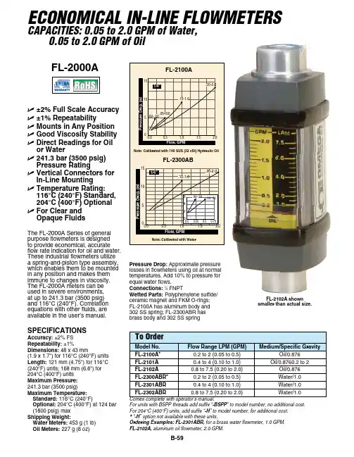
B-59SPeciFicAtioNSAccuracy: ±2% FS Repeatability: ±1%Dimensions: 48 x 43 mm(1.9 x 1.7") for 116°C (240°F) units Length: 121 mm (4.75") for 116°C (240°F) units; 168 mm (6.6") for 204°C (400°F) units Maximum Pressure: 241.3 bar (3500 psig)Maximum temperature: Standard: 116°C (240°F)optional: 204°C (400°F) at 124 bar (1800 psig) max Shipping Weight:Water Meters: 453 g (1 lb) oil Meters: 227 g (8 oz)The FL-2000A Series of general purpose flowmeters is designed to provide economical, accurate flow rate indication for oil and water. These industrial flowmeters utilize a spring-and-piston type assembly, which enables them to be mounted in any position and makes them immune to changes in viscosity. The FL-2000A meters can be used in severe environments, at up to 241.3 bar (3500 psig) and 116°C (240°F). Correlation equations with other fluids, are available in the user’s manual.U ±2% Full Scale Accuracy U ±1% RepeatabilityU Mounts in Any Position U Good Viscosity Stability U D irect Readings for oil or Water U 241.3 bar (3500 psig) Pressure Rating U VU t U F Pressure Drop: Approximate pressure losses in flowmeters using oil at normal temperatures. Add 10% to pressure for equal water flows.connections: 1⁄4 FNPTWetted Parts: Polyphenylene sulfide/ceramic magnet and FKM O-rings; FL-2100A has aluminum body and 302 SS spring; FL-2300ABR has brass body and 302 SS springECONOMICAL IN-LINE FLOWMETERSCAPACITIES: 0.05 to 2.0 GPM of Water, 0.05 to 2.0 GPM of OilFor units with BSPP threads add suffix “-BSPP ” to model number, no additional cost.For 204°C (400°F) units, add suffix “-H ” to model number, for additional cost. * “-H ” option not available with these units.Ordering Examples: FL-2301ABR, for a brass water flowmeter, 1.0 GPM. FL-2102A, aluminum oil flowmeter, 2.0 GPM.FL-2000A0.0510150.5 1.0 1.5 2.0Flow, GPMP r e s s u r e D r o p , p s i1/4"0.00.252460.50.75.02-.20.05-.50.10-1.0.20-2.0FL-2102A shownsmaller than actual size.。

一、便携式超声波流量计特点
高精度测量:线性度优于0.5%,重复性精度优于0.2%,测量精度优于±1%非接触式测量:将带磁性的超声波流量计传感器吸附在管道外壁,即可完成流量测量
测量范围大:选用不同型号的传感器 , 可实现口径 DN15 ~ DN6000mm管道流量的测量
支持中英文菜单:不同版本的流量计 , 可支持中文或英文菜单 , 方便快捷
充电电源:内置大容量镍氢充电电池 ,可支持流量计连续工作20小时以上
内置打印机:既可实现即时屏幕打印 , 还可以定时打印提前设定的多达20余项的测量结果。
内置数据记录器:可将提前设定的多达20余项的测量结果上传至计算机或联网通讯
可以到http://www.yhllj.com/.这里面进行浏览查看
六、编码规则
HD-TUF-2000P 1标准TS-2型举例:HD-TUF-2000P1
2标准TM-1型解释:便携式超声波流量计,标准配置
3标准TL-1型另选配标准小型传感器TS-1型。

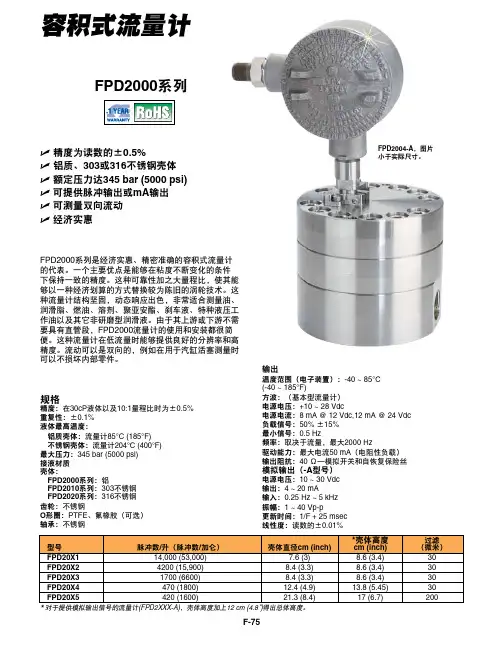
容积式流量计U精度为读数的±0.5%U 铝质、303或316不锈钢壳体U额定压力达345 bar (5000 psi)U可提供脉冲输出或mA输出U可测量双向流动U经济实惠FPD2000系列是经济实惠、精密准确的容积式流量计的代表。
一个主要优点是能够在粘度不断变化的条件下保持一致的精度。
这种可靠性加之大量程比,使其能够以一种经济划算的方式替换较为陈旧的涡轮技术。
这种流量计结构坚固,动态响应出色,非常适合测量油、润滑脂、燃油、溶剂、聚亚安酯、刹车液、特种液压工作油以及其它非研磨型润滑液。
由于其上游或下游不需要具有直管段,FPD2000流量计的使用和安装都很简便。
这种流量计在低流量时能够提供良好的分辨率和高精度。
流动可以是双向的,例如在用于汽缸活塞测量时可以不损坏内部零件。
规格精度:在30cP液体以及10:1量程比时为±0.5%重复性:±0.1%液体最高温度:铝质壳体:流量计85°C (185°F)不锈钢壳体:流量计204°C (400°F)最大压力:345 bar (5000 psi)接液材质壳体:FPD2000系列:铝FPD2010系列:303不锈钢FPD2020系列:316不锈钢齿轮:不锈钢O形圈:PTFE、氟橡胶(可选)轴承:不锈钢输出温度范围(电子装置):-40 ~ 85°C(-40 ~ 185°F)方波:(基本型流量计)电源电压:+10 ~ 28 Vdc电源电流:8 mA @ 12 Vdc,12 mA @ 24 Vdc负载信号:50% ±15%最小信号:0.5 Hz频率:取决于流量,最大2000 Hz驱动能力:最大电流50 mA(电阻性负载)输出阻抗:40 Ω—模拟开关和自恢复保险丝模拟输出(-A型号)电源电压:10 ~ 30 Vdc输出:4 ~ 20 mA输入:0.25 Hz ~ 5 kHz振幅:1 ~ 40 Vp-p更新时间:1/F + 25 msec线性度:读数的±0.01%FPD2004-A,图片小于实际尺寸。

样的压损.PT878GC没有部件会造成积聚或污染,也没有运动部件可被磨损,因此无需润滑也无需或很少需要维护. 用途范围︰开发夹装式超声波气体传感器最大的难度之一在于,很难做到使发射的超声波信号穿过金属管壁,穿过气体,再穿过管壁到达另一个等待接受该超声波信号的传感器中.在气体系统中,传递的声能量能真正被接收到的百分比数为49×10-7,如此少的能量用于可靠测量是远远不够的. 新的夹装式气体传感器产生的信号强度是从前超声波传感器的5~10倍,信号干净,背景噪音极少.随之带来的结果就是,PT878GC流量计系统即使在低密度的气体应用中也有极佳的表现. 即便是第一次使用,也可以在几分钟之内就完成测量--PT878GC 流量计就是这么使用方便.只需输入现场参数、把传感器夹装在管外并调好声程.无需其他辅助工具,也无需在管线上开孔. 型号说明︰传感器美通用总公司专业高科研制的双元传感器壁厚范围 1.3mm~76.2mm 管材大多数标准金属和塑料管精度±1%或±0.05mm 耐温在37℃以下环境中可连续工作;在260℃以下环境中间断工作10秒,然后需要在空气中降温2 分钟技术参数︰流体类型符合最低压力要求的导声气体,见安装需求表. 管线尺寸•2Omm~30Omm, 选用PT878GC—01 •10Omm~61Omm, 选用PT878GC—02 管壁厚管壁越厚,气体密度要求就越高,见安装需求表. 管线材质所有的金属和塑料管.无内衬的管线. 流速精度•管径≤15Omm 读数的±2%~±5% •管径>15Omm 读数的±1%~±2% 注:精度取决于管径和其它因素重复性: 读数的±0.2%~±O.5% 范围(双向):见安装需求表量程比(全范围): 150:1 注:所给性能指标是假定管内流场理想下(通常是满足上游20倍管径的直管段,下游1O倍的管径的直管段)和流速大于15m/s.对于2英寸或更小管径需要至少有3米的连续直管段,没有法兰,焊接或接头测量参数标准流量和实际流量,流速和质量流量安装调试︰流量测量受专利出保护的互相关时差法(Correlation Transit Time) 外壳: IP67防水型外形尺寸: 1.36kg,238×138×38mm 显示: 240×220像素,带背景光的LCD显示键盘: 25键触觉反馈膜橡胶键盘内部电池充电电池:可连续工作8小时充电器输入100~25OVAC,50/6OHz,O.38A 内存FLASN内存,可现场升级版本维护保养︰操作温度-20~55℃储存温度-40~70℃注: 为确保最长电池使用寿命,高于35℃的温度下储存不应超过一个月. 标准输入/输出•一路4~2OmA电流输出•一路用户可选的脉冲(5V)或频率(5V方波100至1000OHz)输出•两路4~20mA模拟输入,带内置电源可用于双线制温度和压力变送器数字通讯接口红外接口与PC机或打印机相连现场参数设定•菜单操作界面,使用键盘和功能键设定•在线帮助功能包括管线参考表格•存储功能用于保存现场参数数据记录•内存容量可记录超过100,000个流量参数•可以通过键盘编辑存储、更新和起止时间显示功能•图形显示功能以数字和图像形式显示流量•显示存储的数据•诊断参数欧洲标准电源系统符合欧洲EMC标准89/336/EEC •PCFG-1用于管径小于30Omm的应用•PCFG-2用于管径大于30Omm的应用耦合剂CPL16 适合使用区域•标准:非防爆区•可选:全天候NENA 4 IP65 •可选:防爆Class1,Div.1, Groups C,D •可选:防爆EXⅡ2G EExmdⅡC T6-T3 注:PT878GC电子部分设计用于非防爆区传感器电缆•标准:一对LEMO®同轴电缆接头及8m手持式超声波气体流量计FLUXUS G601德国FLEXIM流量仪表FLEXIM成立于1990年4月,总部位于德国伯林。
青岛中科金水物联有限公司管段式双声道超声波流量计1.1 ZK-JS100产品简介 (2)1.2 ZK-JS100参数 (2)2 ZK-JS100安装 (2)2.1 安装准备 (2)2.2 接线说明 (3)3 PT-SCAN软件操作 (4)3.1 PT-SCAN 软件安装 (4)3.2 PT-SCAN 主功能菜单 (5)3.3 安装配置功能(SETUP) (6)3.4 流量输出设置功能(FLOW CONFIG) (8)3.5 流量计校准功能(CALIBRATION) (9)3.6 监控功能(MONITOR) (11)3.7 嵌入式软件升级 (12)4 ZK-JS100面板操作 (13)4.1-ZK-JS100面板构成 (13)4.2 密码输入 (15)4.3 参数设置 (15)4.3.1 F-cFG(流量配置) (16)4.3.2 SEtUP(快速配置) (16)4.3.3 StAtE(运行状态) (17)4.4 快速使用指南 (17)4.4.1 使用键盘 (17)4.4.2 使用PT-SCAN软件 (18)4.5 ZK-JS100输出校正 (18)5 ZK-JS100通讯 (19)5.1 ZK-JS100通讯协议 (19)5.2 MODBUS通讯地址表 (20)6 ZK-JS100仪表维护及检修 (22)6.1 正常维护 (22)6.2 异常情况诊断和排除 (22)6.3 技术支持与售后服务 (23)6.4 ZK-JS100的保修说明 (23)附录 (24)A 常用液体性质表 (24)B 水温声速表 (29)概述1.1 ZK-JS100产品简介ZK-JS100双声道超声波流量计是采用美国L&F技术的双道超声波流量测量产品,克服了单声道产品不适应流场变化精度不高流量不稳定的缺点,测量原理仍然基于延时法测量,由于使用两个声道的优化设计,很大程度上克服了紊流随机性对测量的影响,大幅度提高了对不同工况测量的适应性和测量精度,小流量测量更有保证。
1. PRINCIPLE OF OPERATIONA tapered glass flow tube, and a metallic or PTFE float inside it, constitute the heart of model FLD variable area flow meter.Flow meters are installed vertically in lines carrying gases or liquids to be monitored.Fluids enter through the smaller opening at the bottom, and exit through the upper end. Upward pressure causes the float to rise. Flow takes place through the circular area between the float and the inside surface of the flow tube. As the float rises,the flow area increases, due to the tapered bore of the flow tube.Dynamic equilibrium results when the buoyantforce of the float and the upward force, due to fluid pressure, balance the weight of the float.The vertical position of the float at equilibrium corresponds exclusively to one particular flow rate. This flow rate is obtained by determining the height of the float with the aid of the scale on the flow tube.2. MATERIALS OF CONSTRUCTIONFlow Tubes: Heavy walled precision formed borosilicate glassTube Shields:PolycarbonateFloats: 316 stainless steel, or PTFE Wetted Parts: Brass, type 316 stainless steelor PTFE.Seals: ®for brass and stainlessmodels, PTFE for PTFE models. Scales: Direct readingMeters are designed with unique “revolving” scales of dual air-water direct reading graduations showing SCFM and SLPM for AIR, as well as GPM and LPM for WATER. Knurled scale endings accessible at the lower back portion of the meters enable rotation of the scale.3. METER SPECIFICATIONSStandard Accuracy:± 5% FS Repeatability:± 0.25%Max. Operating Pressure: 150 psig/10bars (brass or stainless models); or 100 psig/6.7 bars (PTFE models).Max. Operating Temperature: 250ºF/121ºC (brass or stainless models); or 150 ºF/65ºC (PTFE models. Fittings: 3/8”-18” NPT FemaleAll meters are factory tested for leakage prior to shipping. For hazardous fluids the flow meter must be re-tested at the time of installation in the system, prior to usage. It is also important that a leak integrity test is performed periodically to maintain safe operating conditions. Flow meters must be protected from breakage due to external conditions such as objects bumping into or hitting the instrument, extreme vibrations, or attack by corrosive materials. It is the responsibility of the customer to acquaint the operator(s) of this flow meter with all appropriate safety information.4. INSTALLATION AND OPERATION4.1 Receipt of EquipmentInspect instrument for possible visible damage resulting from shipping. Notify UPS or othercarrier as well as Omega.4.2 InstallationFlow meters must always be installed in vertical position; any significant deviation from vertical will affect readings.Valves must be closed prior to installation and opened gradually after all connections are carefully inspected. A leak test is highly recommended especially when hazardous fluids are involved.CAUTION:Excessive tightening of valves may damage the orifice.It is important that all lines to be connected to the flow meter are purgedof any dust or otherVitonresidual contamination prior to installing the meter. In some applications a filter should be installed at the inlet of the flow meter.4.3 OperationFlow meters are designed to be operated at pressures and temperatures not exceeding recommended maximum values (see above).Close valve (if applicable) before initial use, then gradually pressurize the system.Slowly open the valve until the float is at the desired flow rate. Each scale indicates the “reading line” on the float where the flow rate should be read.5. FLOW TUBE INSTALLATION/REMOVALƽ Do not remove the flow tube from the flowmeter. Please contact Customer Service.6. MAINTENANCEƽ Do not remove the flow tube from the flowmeter. Please contact Customer Service.Under normal operating conditions no special maintenance is required. Dirt or contamination may create problems within the flow tube bycausing a restriction in the flow passage. Such conditions can be diagnosed by examining the flow tube.The most obvious indication of obstructions is the float being stuck in the flow tube. If the existence of contamination is determined the condition may be rectified in a number of ways. The easiest being (if possible), to disconnect the inlet and the outlet of the flow meter and purge the instrument by using a clean and dry stream of gas.Action of the float within the bore of the flow tube very often facilitates particles or impediments to be dislodged through the outlet of the flow meter .。
P-2000ow n e r ’s m a n u a l W H E N A C C U R A C Y I S T H E P O I N T .®TMTABLE OF CONTENTS 2P-2000 Features3Key Functions3Check Calibration4To Set the Scale4To Change the Set-Point5Information About Y our Readings 5To Check the Accumulated Readings 6To Reset the Meter6Applications7Using the 0-100 Arbitrary Scale7Testing Baled Scrap Paper8Care of Y our Meter9Service for Y our Meter10WarrantyRead Key Calibration Check Key #Set-Point Key $Scale Key@! 2000Press this key to read the %MC or relative moisturevalue of the material under test.Check:This key, when pressed with the Read key, checks themeter calibration. It also displays the number of readings in memory (up to 100), the average, and the higheststored reading. It also clears the memory.Set-Point:This key programs the set-point value. A buzzer will alert you if the meter reads higher than the selected value. Italso acts as a scroll key, depending on the function.Scale:This key sets the display scale to #1 (paper), #2 (refer-ence), #3 (baled scrap paper).It also acts as a scroll key, depending on the function.CHECK CALIBRATIONSet the meter to Scale@and the read keyis in calibration if it displays 11.1% +/-0.2.When checking calibration, there is no need to disconnect the external electrode, if attached.If you check the calibration and the display does not read 11.1%, it is likely an indication of a low battery. If this occurs, change the battery immediately.Disconnect the battery. Press and hold the Read key for 15 sec-onds. Release the Read key. Press and hold the Check key for 15 seconds. Release the Check key. Connect a fresh battery to the lead wire in a single action, making sure to align the poles prop-erly and without interrupting contact. If the display remainsfrozen, repeat the procedure. If this procedure does not solve the problem, refer to the Service for Y our Meter section.456A few meter readings in a limited number of specific areas of a large mass can not be projected to indicate an average moisture content of an entire bale.The readings can be very helpful in providing an indication of the overall moisture con-dition inside the bale and to detect areas of excessive mois-ture.Meter readings may be used as an arbitrary guideline in determining whether or not to accept or reject the material. Since checking the moisture condition of bales is performed when buying and selling, the specific value of the meter read-ings remains an element to be agreed upon between buyer and seller. Such an agreement should consider not only a spe-cific “range” of readings, but the number and location of where they are taken.The following ranges can be used as a guideline and may help to interpret the readings:h Readings of 5%–10%, with EMC to 60% RH are usuallyconsidered “dry”.h Readings from 11%–20% with EMC to 95% are usuallyconsidered “acceptable” but should be taken with somereservation.h Readings of 20%-40% are considered “wet” and unac-ceptable.CARE OF YOUR METERTo keep your meter in good working order:h Store your meter in a clean, dry place. The protectivecarrying case provided is an ideal storage place whenthe meter is not in use.h Change the 9-Volt battery as needed. Continued use with alow battery may cause the meter to go out of calibration.h Change contact pins as needed. Keep pin retainers handtightened.h Clean the meter, contact pins, and probes with anybiodegradable cleaner. Use the cleaner sparingly and onexternal parts only. Keep the cleaner out of the external con-nector. DO NOT IMMERSE THE METER OR ANY ELEC-TRODE IN WATER.h Remove the battery if the meter will not be used for onemonth or longer.8NOTESNOTESNOTES51 Indian Lane EastTowaco, NJ 07082(877)-DELMHORST ******************©2006, Delmhorst Instrument Co.510INS-0013REV. 9/14W H E N A C C U R A C Y I S T H E P O I N T .®For over 65 years Delmhorst Instrument has been the leading manufacturer of high quality, US-made moisture meters and ther-mo-hygrometers. Today we offer a wide range of meters for appli-cations including water damage restoration, construction, floor-ing, lumber/woodworking, paper,and agriculture.。
FlowmetersFor liquid Flow of 0.03 to 475 GPHF-17FLR2008FLR2004shown smaller than actual size.U G ood for Many Aggressive/Corrosive Slurries or Liquids U N EMA 4X (IP66) Enclosure U M easures Flow Rate and Total Flow U R S 232CommunicationsThe FLR-2000 Series meters and FLV-2000 Series offer a solution for real-time metering and control of chemicals which are injected, pumped, dosed or dispensed.Flow ranges of less than 0.07 GPH to 79.20 GPH at pressures from 20 to 250 psi meet the general range of use in water, waste water, industrial, CPI, food and beverage, and pharmaceutical marketplaces. The ±1% full scale accuracy insures precision. A 4 line x 20 character digital display enablesthe user to gather information, reset totalizer and input control commands within seconds. RS232 or 0 to 5 Vdc and relay outputs are standard. An advanced material coating process combined with a PVC body provide resistance to aggressive flow media. The wet side of the flow system is isolated from the electronics yet close coupled for easy installation, operation and maintenance. FLV-2000 models allow the user to remotely set a pump rate or proprtional valve setting.SpecificationsAccuracy: ± 1% full scaleRepeatability: ± 0.5% full scale Linearity: ± 0.25% full scaleResponse Time (Typical): 50 mSVolume Flow Units: GPM, GPH, CCM, LPMTemperature Range: 0 to 70°C (32 to 158°F)Temperature Coefficient: 0.05%/°C Turndown Ratio: 50:1Standard Conditions: 25°C and 1 atmosphereMaximum Pressure: 17.2 bar (250 psig)Humidity Range: 0 to 100%Supply Current: 0.25 A with back lighting on meters, 0.35 A with back lighting on controllersSupply Voltage: 15.0 Vdc maximum @ 300 mA maximum current on meters and 500 mA on controllersInput Standard Signals: 1 digital input, TTL/CMOS compatible; 1 analog input, 0 to 5 Vdc equals maximum flowOutput Standard Signals: 2 analog 0 to 5 Vdc outputs flow rate; 1 RS232 serial port, 19200 baud rate, 1 dry closure relay output, SPDT 0.5 A DC for flow/no flowSetpoint Output: FLV models use one of available 0 to 5 Vdc outputs for a remote setpoint signal; RS232 also available for outputPower Consumption: Less than 3.5 W Indicating Display: 4 line x 20 character back light LCDInterface Screens: Membrane touch switch with 11 menu screens Connectors:Electrical: Weather tight circular high-density connectors Mechanical: 1⁄2" NPTStandard Wetted Materials: PVC, FKM O-rings Dimensions:26.03 H x 18.09 W x 12.3 cm D (10.25 x 7.125 x 4.875")Pressure Drop: Typical, full scale,20 to 60 psiF-18Ordering Examples: FLR2006, 50 cc/min max flowmeter. FLV2003, 5 cc/min max flowmeter with remote setpoint.FLV2003PHP-314-GFLR2004F。