F601超声波流量计说明书
- 格式:pdf
- 大小:1.53 MB
- 文档页数:4
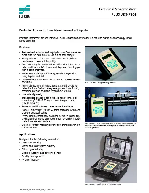
Technical SpecificationFLUXUS® F601FLUXUSsupported by handleMeasurement with transducers mounted by mounting frames and flow transmitter fixed to the pipe by the QuickFix pipe mounting fixtureMeasurement equipment in transport caseF601Portable Ultrasonic Flow Measurement of LiquidsPortable instrument for non-intrusive, quick ultrasonic flow measurement with clamp-on technology for all types of pipingFeatures•Precise bi-directional and highly dynamic flow measure-ment with the non-intrusive clamp-on technology •High precision at fast and slow flow rates, high tem-perature and zero point stability•Portable, easy-to-use flow transmitter with 2 flow chan-nels, multiple inputs/outputs, an integrated data logger with a serial interface•Water and dust-tight (NEMA 4); resistant against oil, many liquids and dirt•Li-Ion battery provides up to 14 hours of measurement operation•Automatic loading of calibration data and transducer detection for a fast and easy set-up (less than 5 min), providing precise and long-term stable results •User-friendly design•Transducers available for a wide range of inner pipe diameters () and fluid temperatures ()•Probe for wall thickness measurement available•Robust, water-tight (NEMA 4) transport case with com-prehensive accessories•HybridTrek automatically switches between transit time and NoiseTrek mode of measurement when high partic-ulate flows are encountered•QuickFix for fast mounting of the flow transmitter in diffi-cult conditionsApplicationsDesigned for the following industries:•Chemical industry•Water and wastewater industry •Oil and gas industry•Cooling systems and air conditioners •Facility management •Aviation industry0.25 to 256 in -40 to +752 °FFLUXUS® F601Technical Specification Table of Contents Function (3)Measurement Principle (3)Calculation of Volumetric Flow Rate (3)Number of Sound Paths (4)Typical Measurement Setup (5)Flow Transmitter (6)Technical Data (6)Dimensions (8)Standard Scope of Supply (9)Connection of Adapters (10)Example for the Equipment of a Transport Case (11)Transducers (12)Transducer Selection (12)Transducer Order Code (13)Technical Data (14)Transducer Mounting Fixture (17)Coupling Materials for Transducers (21)Connection Systems (22)Transducer Cable (22)Clamp-on Temperature Probe (optional) (23)Wall Thickness Measurement (optional) (24)Technical Specification FLUXUS® F601FunctionMeasurement PrincipleTransit Time Difference PrincipleIn order to measure the flow of a medium in a pipe, ultrasonic signals are used, employing the transit time dif-ference principle. Ultrasonic signals are emitted by a transducer installed on the pipe and received by a sec-ond transducer. These signals are emitted alternately in the flow direction and against it.As the medium in which the signals propagate is flowing, the transit time of the ultrasonic signals in the flow direction is shorter than against the flow direction.The transit time difference, ∆t, is measured and allows the flowmeter to determine the average flow velocity along the propagation path of the ultrasonic signals. A flow profile correction is then performed in order to ob-tain the area averaged flow velocity, which is proportional to the volumetric flow rate.Two integrated microprocessors control the entire measuring process. This allows the flowmeter to remove disturbance signals, and to check each received ultrasonic wave for its validity which reduces noise.HybridTrekIf the gaseous or solid content in the medium increases occasionally during measurement, a measurement with the transit time difference principle is no longer possible. NoiseTrek mode will then be selected by the flowmeter. This measurement method allows the flowmeter to achieve a stable measurement even with high gaseous or solid content.The transmitter can switch automatically between transit time and NoiseTrek mode without any changes to the measurement setup.Calculation of Volumetric Flow Rate= k Re . A . k a . ∆t/(2 . t fl )wherePath of the ultrasonic signal Transit time difference ∆t=volumetric flow ratek Re =fluid mechanics calibration factor A =cross-sectional pipe area k a =acoustical calibration factor ∆t =transit time difference t fl=transit time in the mediumV ·V ·FLUXUS® F601Technical SpecificationNumber of Sound PathsThe number of sound paths is the number of transits of the ultrasonic signal through the medium in the pipe. Depending on the number of sound paths, the following methods of installation exist:•reflect arrangementThe number of sound paths is even. Both of the transducers are mounted on the same side of the pipe. Correct positioning of the transducers is easier.•diagonal arrangementThe number of sound paths is odd. Both of the transducers are mounted on opposite sides of the pipe.•direct modeDiagonal mode with 1 sound path. This should be used in the case of a high signal attenuation by the medi-um, pipe or coatings.The preferred method of installation depends on the application. While increasing the number of sound paths increases the accuracy of the measurement, signal attenuation increases as well. The optimum number of sound paths for the parameters of the application will be determined automatically by the transmitter.As the transducers can be mounted with the transducer mounting fixture in reflect arrangement or diagonal ar-rangement, the number of sound paths can be adjusted optimally for the application.a = transducer distancenegative transducer distanceTechnical Specification FLUXUS® F601Typical Measurement Setuppower supply unit/battery charging unitExample of a measurement setup in reflect arrangementFLUXUS® F601Technical SpecificationFlow TransmitterTechnical DataFLUXUSF601designportablemeasurementmeasurement principle transit time difference correlation principle,automatic NoiseTrek selection for measurements with high gaseous or solid content flow velocity 0.03 to 82 ft/srepeatability 0.15 % of reading ±0.03 ft/smediumall acoustically conductive liquids with < 10 % gaseous or solid content in volume (transit time difference principle)temperature compensation corresponding to the recommendations in ANSI/ASME MFC-5.1-2011accuracy 1with standard calibration with advanced calibration (optional)with field calibration 2±0.5 % of reading ±0.03 ft/sflow transmitter power supply 100 to 240 V/50 to 60 Hz (power supply unit),10.5 to 15 V DC (socket at transmitter),integrated battery batteryLi-Ion, 7.2 V/4.5 Ahoperating time (without outputs, inputs and backlight): > 14 h power consumption< 6 W number of flow measuring channels2signal attenuation0 to 100 s, adjustable measuring cycle (1 channel)100 to 1000 Hzresponse time 1 s (1 channel), option: 70 ms housing material PA, TPE, AutoTex, stainless steel degree of protection NEMA 4dimensions see dimensional drawing weight 4.2 lbfixationQuickFix pipe mounting fixture ambient temperature 14 to 140 °Fdisplay2 x 16 characters, dot matrix, backlight menu languageEnglish, German, French, Dutch, Spanishmeasuring functions physical quantities volumetric flow rate, mass flow rate, flow velocity,heat flow (if temperature inputs are installed)totalizervolume, mass, optional: heat quantity calculation functions average, difference, sumdiagnostic functions sound speed, signal amplitude, SNR, SCNR, standard deviation of amplitudes and transit times data logger loggable values all physical quantities, totalized values and diagnostic values capacity> 100000 measured values1for transit time difference principle, reference conditions and v > 0.49 ft/s 2reference uncertainty < 0.2 %±1.6 % of reading ±0.03 ft/s ±1.2 % of reading ±0.03 ft/sTechnical Specification FLUXUS® F601 communicationinterface RS232/USBserial data kitsoftware (all Windows™ ver-sions)-FluxData: download of measurement data, graphical presentation, conversion to other formats (e.g. for Excel™)-FluxKoef: creating medium data sets-FluxSubstanceLoader: upload of medium data setsсable RS232adapter RS232 - USBtransport casedimensions19.7 x 15.7 x 7.5 inoutputsThe outputs are galvanically isolated from the transmitter. number see standard scope of supply on page 9, max. on request accessories output adapter (if number of outputs > 4)current outputrange0/4 to 20 mAaccuracy0.1 % of reading ±15 μAactive output R ext < 200 Ωpassive output U ext = 4 to 16 V, depending on R extR ext < 500 Ωfrequency outputrange0 to 5 kHzopen collector24 V/4 mAbinary outputoptorelay26 V/100 mAbinary output as alarm output-functions limit, change of flow direction or errorbinary output as pulse output-pulse value0.01 to 1000 units-pulse width 1 to 1000 msinputsThe inputs are galvanically isolated from the transmitter. number see standard scope of supply on page 9, max. 4 accessories input adapter (if number of inputs > 2)temperature inputtype Pt100/Pt1000connection4-wirerange-238 to +1040 °Fresolution0.01 Kaccuracy±0.01 % of reading ±0.03 Kcurrent inputaccuracy0.1 % of reading ±10 μApassive input R i = 50 Ω, P i < 0.3 W-range-20 to +20 mAvoltage inputrange0 to 1 Vaccuracy0.1 % of reading ±1 mVinternal resistance R i = 1 MΩFLUXUS F601FLUXUS® F601Technical Specification DimensionsTechnical Specification FLUXUS® F601 Standard Scope of SupplyFLUXUS® F601Technical Specification Connection of AdaptersExample for the Equipment of a Transport Caseserial data kitpower supply unit, mains cabletransducer mounting fixturemeasuring tapetransmittertransducersuser manual,Quick Start Guidecoupling compoundwall thickness probe (optional)QuickFix pipe mounting fixturetemperature probes (optional)TransducersTransducer Selectiontransducer order codeFSK 3.97.9141.7255.9 FSM2 3.978.7133.9FSQ0.390.98 5.915.7FSS0.240.39 2.80.20.4242040200inner pipe diameter [in] recommended possibleTransducer Order Code1, 2345, 67, 89 to 1112, 13no. of character t r a n s d u c e rt r a n s d u c e r f r e q u e n c y-a m b i e n t t e m p e r a t u r ee x p l o s i o n p r o t e c t i o nc o n n e c t i o n s y s t e m-e x t e n s i o n c a b l e/o p t i o ndescriptionFSset of ultrasonic flow transducers for liquids measurement, shear wave K0.5 MHzM 1 MHz Q 4 MHz S 8 MHzN normal temperature rangeEextended temperature range (shear wave transducers with trans-ducer frequency M, Q)NNnot explosion proof NLwith Lemo connectorXXXcable length in m, for max. length of extension cable see page 22 LClong transducer cable (only FSK)example FSM-NNNNL-000shear wave transducer 1 MHz, normal temperature range,connection system NL with Lemo connector--/Technical DataShear Wave TransducersShear Wave TransducersShear Wave Transducers (extended temperature range)Transducer Mounting FixtureOrder Code1, 234567 to 9no. of character t r a n s d u c e r m o u n t i n g f i x t u r et r a n s d u c e r-m e a s u r e m e n t a r r a n g e m e n ts i z e-f i x a t i o no u t e r p i p e d i a m e t e rdescriptionFS mounting framesLM ladder chain mounting accessory VP portable Variofix TB tension beltsWLtransducer box for WaveInjectorA all transducersK transducers with transducer frequency K M transducers with transducer frequency M Q transducers with transducer frequency Q Stransducers with transducer frequency SD reflect arrangement or diagonal arrangement/direct mode Rreflect arrangement S small Mmedium C chains Nwithout fixation L080.5 to 8 in L220.5 to 22 in 0100.39 to 3.9 in 0250.39 to 9.8 in 0550.39 to 21.7 in 150 2 to 59.1 in 2102 to 82.7 inexample VPA-DM-C055portable Variofix and chains --ladder chain mounting accessory LMTechnical Specification FLUXUS® F601Coupling Materials for TransducersTechnical Datanormal temperature range(4th character of transducer ordercode =N)extended temperature range(4th character of transducer ordercode =E)WaveInjector WI-400< 212 °F < 338 °F< 302 °F < 392 °F< 536 °F536 to 752 °Fcoupling compound type N coupling compound type Ecoupling compound type E coupling compound type E or Hcoupling foil type A and coupling foil type VTcoupling foil type B and coupling foil type VTtypeorder code ambient temperature materialremark°Fcoupling compound type N990739-1-22 to +266mineral grease paste coupling compound type E990739-2-22 to +392silicone paste coupling compound type H990739-3-22 to +482fluoropolymer paste coupling foil type A 990739-7max. 536lead coupling foil type B990739-8> 536 to 752silvercoupling foil type VT 990739-014 to +392fluoroelastomerfor transducers with transducerfrequency G, H, K990739-6for shear wave transducers with transducer frequency M, P990739-14for shear wave transducers IP68 and Lambwave transducers with transducer frequency M, P990739-5for transducers with transducer frequency Qcoupling foil not to be used for transducer mounting fixture with magnetsFLUXUS® F601Technical SpecificationConnection SystemsTransducer CableTechnical Datatransducer frequency (3d character of transducerorder code)G, H, K M, P Q S N Lx y l 1xy l 1x y l 1x y l cable length ft69≤ 8266≤ 8263≤ 8233≤ 65cable length (option LC)ft622≤ 82---------1> 82 to 328 ft on requestx, y = transducer cable length l = max. length of extension cabletransducer cableextension cabletype169925511750standard length ft see table above 1632max. lengthft -see table above 32ambient temperature °F-67 to +392-13 to +176< 144sheath materialstainless steel 304--outer diameter in0.31--cable jacket materialPTFE TPE-O PE outer diameter in 0.110.310.24thickness in0.010.02color brown black black shieldxxx-Technical Specification FLUXUS® F601Clamp-on Temperature Probe (optional)Technical DataConnectionTemperature ProbeConnectorCabletechnical type PT13N PT13N PT13F PT13F order code 670413-1670412-1670413-2670412-2design short response timetypePt10002x Pt1000 matched according to EN 1434-1Pt10002x Pt1000 matchedaccording to EN 1434-1connection4-wire 4-wire measuring range °F-22 to +482-58 to +482accuracy T ±(0.27 °F + 2 . 10-3 . (|T [°F]| - 32 °F)), class A±(0.27 °F + 2 . 10-3 . (|T [°F]| - 32 °F)), class Aaccuracy ∆T-≤ 0.1 K(3 K < ∆T < 6 K), more corresponding to EN 1434-1-≤ 0.1 K(3 K < ∆T < 6 K), more corresponding to EN 1434-1response times508housingaluminum PEEK, stainless steel 304, copperdegree of protection NEMA 4NEMA 4weight (without con-nector)lb0.6 1.10.7 1.4fixationclamp-onclamp-onaccessoriesthermal conductivity paste 392 °Fx x thermal conductivity foil 482 °Fx x plastic protection plate, insulation foam -xdimensions length l in0.590.55width b in 0.59 1.18height hin0.79 1.06dimensional drawingA Bpin cable of temperature probeextension cable1white/blue blue 2red/bluegray3, 4, 5not connected6red red 7whitewhite8not connectedcable of temperature probe extension cabletype4 x 0.25 mm² black or white LIYCY 8 x 0.14 mm² gray standard length ft 916/32/82max. length ft-656cable jacketPTFEPVCABred/blueredwhite/bluewhiteWall Thickness Measurement (optional)The pipe wall thickness is an important pipe parameter which has to be determined exactly for a good mea-surement. However, the pipe wall thickness often is unknown.The wall thickness probe can be connected to the transmitter instead of the flow transducers and the wall thickness measurement mode is activated automatically.Acoustic coupling compound is applied to the wall thickness probe which then is placed firmly on the pipe.The wall thickness is displayed and can be stored directly in the transmitter.Technical DataCabletechnical type DWR1NZ7measuring range 1in 0.04 to 9.8resolution in 0.0004accuracy1 % ± 0.004 in medium temperature °F-4 to +392,short-time peak max. 932сable type 2616lengthft41 The measuring range depends on the attenuation of the ultrasonic signal in thepipe. For strongly attenuating plastics (e.g. PFA, PTFE, PP) the measuring range is smaller.type2616ambient temperature °F<392cable jacket materialFEP outer diameter in0.2color black shieldxDWR1NZ7FLEXIM AMERICAS Corporation Edgewood, NY 11717USATel.:(631) 492-2300Fax:(631) 492-2117internet: e-mail:*****************1-888-852-7473 Subject to change without notification. Errors excepted. FLUXUS® is a registered trademark of FLEXIM GmbH.。
FLEXIM超声波流量计使用步骤详解步骤一:设置流量计1.首先,将流量计安装在需要测量的管道上。
确保流量计的传感器与管道平行,并且没有任何障碍物。
2.打开流量计的电源开关,并确保仪表显示屏亮起。
3.使用流量计上的操作界面或控制器,进入参数设置界面。
根据实际需求设置传感器的型号和管道的参数,例如直径、流体类型等。
4.根据实际情况,选择流速单位和流量单位,并进行设置。
通常情况下,流速单位为m/s,流量单位为m³/h。
5.进入传感器对准界面,使用仪表上的显示屏或控制器上的操作按钮,调整传感器位置和对准角度,确保传感器与管道的中心对齐,并且传感器的角度适当。
步骤二:进行校准1.进入校准界面,选择校准模式。
通常有两种模式可选:速度模式和流量模式。
速度模式下,将测量流速,并校准为实际单位;流量模式下,将测量流量,并校准为实际单位。
2.启动校准,将流量计的传感器浸入已知流速或流量的介质中,等待一段时间,直到测量稳定。
3.根据校准模式选择相应的校准参数,并进行校准。
校准完成后,保存校准参数,并退出校准界面。
步骤三:开始测量1.返回主界面,确认流量计的工作状态正常。
如果有任何异常情况,例如测量值不稳定、传感器异常等,应及时进行排查和处理。
2.将介质流动起来,确保流量计获取到稳定的流动信号。
3.监测仪表上的显示屏或控制器上的参数,包括流速、流量、温度等,并实时记录。
4.结束测量后,关闭流量计的电源开关。
步骤四:数据处理和分析1.将测量到的数据导出到计算机或其他数据处理设备中,进行数据处理和分析。
2.根据实际需求,使用相应的软件工具,对数据进行处理和计算,例如求平均值、峰值等。
3.根据处理后的数据,生成报告或图表,用于相关部门或人员的分析和决策。
总结:使用FLEXIM超声波流量计FLUXUSF601需要依次进行设置、校准、测量和数据处理四个步骤。
正确的使用流程和规范的操作方法,可以保证测量结果的准确性和可靠性。
FLS F6.60电磁流量计安全说明通用说明• 必须按以下说明手册安装并使用产品。
• 此产品设计用于连接其他仪表,如果使用不当,这些仪表可能存在危险。
在使用前,应阅读所有相关仪表手册,并遵守相关规定。
• 产品安装与接线只能由有资质的人员完成。
• 请勿改动产品构造。
安装与调试说明• 在进行输入与输出接线之前,应切断仪表电源。
• 仪表使用不得超过极限值规定。
• 要清洁设备单元,请只使用兼容化学制品。
包装清单请核实产品完整,并且没有任何损坏。
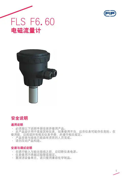
必须包含以下物品:• F6.60 电磁流量计• F6.60 电磁流量计说明手册• 带接口软件的 USB 笔式驱动器• 用于仪表/电脑接口的 USB 电缆说明新型 FLS F6.60 是一种无移动机械部件的流量计,可以用于测量具有导电性的匀质污染液体。
F6.60可以提供三种不同的选项:与FLS流量监视器相连的频率输出,长距离传输和PLC连接的4-20mA输出,以及新的可自由设置的体积脉冲输出。
F6.60插入型电磁流量计装有USB接口和完整专用软件(可从FLS网站免费下载),可以通过电脑按照特殊的安装要求轻松设置所有参数(例如满刻度和截止参数)。
此特定设计可以在DN15(0.5”) - DN600(24”)的宽范围管道尺寸内实现精确的流量测量。
技术数据通用• 管道尺寸范围:DN15 至 DN600(0.5”至 24”)• 最大流量范围:0.05 - 8m/s(0.15 - 26.24 ft./s)• 满量程:8 m/s (26.24 ft/s)• 线性:读数的± 1% + 1.0 cm/s• 可重复性:读数的± 0.5%• 外壳:IP65• 材料:- 箱体:PC/ABS- 垫片:EPDM• 焊接材料:- 传感器本体:316L SS/PVDF;316L SS/PEEK;CuNi合金/PVDF- O形圈:EPDM或FPM- 电极:316L SS 或 CuNi 合金电气• 电源:- 12 - 24VDC±10% 稳压(逆极性和短路保护)- 最大电流:消耗量:250 mA- 保护性接地:< 10 Ω• 电流输出:- 4-20 mA,隔离- 最大环路阻抗:800Ω(24VDC)- 250Ω(12VDC)- 正流量指示或负流量指示• 固态继电器输出:- 用户可选择:最小值警报、最大值警报、体积测定、脉冲输出、窗口警报、关闭- 光隔离,50mA最大漏电流,24VDC最大上拉电压- 最大脉冲/分钟:300- 迟滞:用户可选择• 开路集电极输出(频率):- 类型:开路集电极NPN- 频率:0 – 800 Hz- 最大上拉电压:24 VDC- 最大电流:50 mA,限流- 与FLS M9.02、M9.03、M9.50兼容• 开路集电极输出(方向):- 类型:开路集电极NPN- 最大上拉电压:24 VDC- 最大电流:50mA,限流- 电流方向:0 VDC 箭头方向+ VDC 箭头反向环境• 存储温度:-30°C - +80°C(-22°F - 176°F)• 环境温度:-20°C - +70°C(-4°F - 158°F)•相对湿度:0 - 95%(无结露)• 液体条件:- 均质液体、糊剂或料浆,还有固体成份- 最小电导率:20 μS- 温度:PVDF底部版本:-10°C - +60°C(14°F - 140°F)PEEK底部版本:-10°C - +150°C(14°F - 302°F)• 最大工作压力:- 16 bar @ 25°C (232 psi @ 77°F)- 8.6 bar @ 60°C (124 psi @ 140°F)标准和认证•按照ISO 9001要求制造•按照ISO 14001要求制造•CE•RoHS合规性•GOST R尺寸A 传感器本体B F6.60 电磁流量计1 O形圈(EPDM 或 FPM)2 传感器本体(316L SS 或 CuNi)3 隔离板(PVDF 或 PEEK)4 电极(316L SS 或 CuNi)5 电缆填料盖6 管件内安装使用的 ABS 端帽7 电子盒安装管道位置• 图1中显示的六个最普通的安装配置有助于在管道中为转轮式流量传感器和电磁流量传感器选择最佳位置。
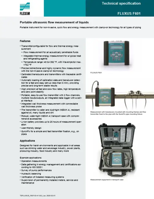
Features•Transmitterconfigurable for flow and thermal energy mea-surement–Flow measurement for all acoustically penetrable fluids–Integrated thermal energy measurement for a typical heat and refrigerating agents–Temperature range -40 to+392 °F, with WaveInjector max.+752 °F•Precise bidirectional and highly dynamic flow measurementwith the non-invasive clamp-on technology•Calibrated transducers and transmitters with traceable certif-icates•Automatic loading of calibration data and transducer detec-tion for a fast and easy set-up (less than 5 min), providing precise and long-term stable results•High precision at fast and slow flow rates, high temperature and zero point stability•Portable, easy-to-use flow transmitter with 2 flow channels, multiple inputs/outputs, an integrated data logger with a seri-al interface•Integrated wall thickness measurement with connectable wall thickness probe•The transmitter is water and dust-tight (NEMA 4), resistant against oil, many liquids and dirt•Robust, water-tight (NEMA 4) transport case with compre-hensive accessories•Li-Ion battery provides up to 25 hours of measurement oper-ation•User-friendly design•QuickFix for a simple and fast transmitter fixation, e.g., on pipesApplicationsDesigned for harsh environments and applicable in all areas such as drinking water and sewerage industry, power plants, producing industry, food industry and many moreExample applications:•Operation measurements•Data gathering in energy management and certifications ac-cording to ISO 50001•Survey of pump performances•Hydraulic balancing•Verification of installed measuring systems•Supervision of permanently installed meters, service and maintenance FLUXUS F601Measurement with transducers mounted with mounting frames and flow transmitter fixed to the pipe with the QuickFix pipe mounting fixture Measurement equipment in transport casePortable ultrasonic flow measurement of liquidsPortable instrument for non-invasive, quick flow and energy measurement with clamp-on technology for all types of pipingTSFLUXUS_F601V2-4-1US_Lus, 2020-02-01FLUXUS F601Technical specification2020-02-01, TSFLUXUS_F601V2-4-1US_Lus2Function . . . . . . . . . . . . . . . . . . . . . . . . . . . . . . . . . . . . . . . . . . . . . . . . . . . . . . . . . . . . . . . . . . . . . . . . . . . . . . . . . . . . . . .3Measurement principle. . . . . . . . . . . . . . . . . . . . . . . . . . . . . . . . . . . . . . . . . . . . . . . . . . . . . . . . . . . . . . . . . . . . . . . . . . . . .3Calculation of volumetric flow rate . . . . . . . . . . . . . . . . . . . . . . . . . . . . . . . . . . . . . . . . . . . . . . . . . . . . . . . . . . . . . . . . . . . .3Number of sound paths . . . . . . . . . . . . . . . . . . . . . . . . . . . . . . . . . . . . . . . . . . . . . . . . . . . . . . . . . . . . . . . . . . . . . . . . . . . .4Typical measurement setup. . . . . . . . . . . . . . . . . . . . . . . . . . . . . . . . . . . . . . . . . . . . . . . . . . . . . . . . . . . . . . . . . . . . . . . . .5Transmitter . . . . . . . . . . . . . . . . . . . . . . . . . . . . . . . . . . . . . . . . . . . . . . . . . . . . . . . . . . . . . . . . . . . . . . . . . . . . . . . . . . . . .6Technical data . . . . . . . . . . . . . . . . . . . . . . . . . . . . . . . . . . . . . . . . . . . . . . . . . . . . . . . . . . . . . . . . . . . . . . . . . . . . . . . . . . .6Dimensions. . . . . . . . . . . . . . . . . . . . . . . . . . . . . . . . . . . . . . . . . . . . . . . . . . . . . . . . . . . . . . . . . . . . . . . . . . . . . . . . . . . . . .7Standard scope of supply. . . . . . . . . . . . . . . . . . . . . . . . . . . . . . . . . . . . . . . . . . . . . . . . . . . . . . . . . . . . . . . . . . . . . . . . . . .8Adapters. . . . . . . . . . . . . . . . . . . . . . . . . . . . . . . . . . . . . . . . . . . . . . . . . . . . . . . . . . . . . . . . . . . . . . . . . . . . . . . . . . . . . . . .8Example for the equipment of a transport case . . . . . . . . . . . . . . . . . . . . . . . . . . . . . . . . . . . . . . . . . . . . . . . . . . . . . . . . . .9Transducers . . . . . . . . . . . . . . . . . . . . . . . . . . . . . . . . . . . . . . . . . . . . . . . . . . . . . . . . . . . . . . . . . . . . . . . . . . . . . . . . . . .10Transducer selection . . . . . . . . . . . . . . . . . . . . . . . . . . . . . . . . . . . . . . . . . . . . . . . . . . . . . . . . . . . . . . . . . . . . . . . . . . . . .10Transducer order code. . . . . . . . . . . . . . . . . . . . . . . . . . . . . . . . . . . . . . . . . . . . . . . . . . . . . . . . . . . . . . . . . . . . . . . . . . . .11Technical data . . . . . . . . . . . . . . . . . . . . . . . . . . . . . . . . . . . . . . . . . . . . . . . . . . . . . . . . . . . . . . . . . . . . . . . . . . . . . . . . . .12Transducer mounting fixture . . . . . . . . . . . . . . . . . . . . . . . . . . . . . . . . . . . . . . . . . . . . . . . . . . . . . . . . . . . . . . . . . . . . . .14Coupling materials for transducers . . . . . . . . . . . . . . . . . . . . . . . . . . . . . . . . . . . . . . . . . . . . . . . . . . . . . . . . . . . . . . . .17Connection systems . . . . . . . . . . . . . . . . . . . . . . . . . . . . . . . . . . . . . . . . . . . . . . . . . . . . . . . . . . . . . . . . . . . . . . . . . . . .18Clamp-on temperature probe (optional). . . . . . . . . . . . . . . . . . . . . . . . . . . . . . . . . . . . . . . . . . . . . . . . . . . . . . . . . . . . .19Technical data . . . . . . . . . . . . . . . . . . . . . . . . . . . . . . . . . . . . . . . . . . . . . . . . . . . . . . . . . . . . . . . . . . . . . . . . . . . . . . . . . .19Fixation. . . . . . . . . . . . . . . . . . . . . . . . . . . . . . . . . . . . . . . . . . . . . . . . . . . . . . . . . . . . . . . . . . . . . . . . . . . . . . . . . . . . . . . .20Wall thickness measurement (optional). . . . . . . . . . . . . . . . . . . . . . . . . . . . . . . . . . . . . . . . . . . . . . . . . . . . . . . . . . . . .21Technical data . . . . . . . . . . . . . . . . . . . . . . . . . . . . . . . . . . . . . . . . . . . . . . . . . . . . . . . . . . . . . . . . . . . . . . . . . . . . . . . . . .21Technical specification FLUXUS F6013TSFLUXUS_F601V2-4-1US_Lus, 2020-02-01FunctionMeasurement principleThe transducers are mounted on the pipe which is completely filled with the fluid. The ultrasonic signals are emitted alter-nately by a transducer and received by the other. The physical quantities are determined from the transit times of the ultra-sonic signals.Transit time difference principleAs the fluid where the ultrasound propagates is flowing, the transit time of the ultrasonic signal in flow direction is shorter than the one against the flow direction.The transit time difference Δt is measured and allows the flowmeter to determine the average flow velocity along the prop-agation path of the ultrasonic signals. A flow profile correction is then performed in order to obtain the area averaged flow velocity, which is proportional to the volumetric flow rate.The integrated microprocessors control the entire measuring cycle. The received ultrasonic signals are checked for mea-surement usability and evaluated for their reliability. Noise signals are eliminated.HybridTrekIf the gaseous or solid content in the fluid increases occasionally during measurement, a measurement with the transit time difference principle may no longer be possible. NoiseTrek mode will then be selected by the flowmeter. This mea-surement method allows the flowmeter to achieve a stable measurement even with high gaseous or solid content.The transmitter can switch automatically between transit time and NoiseTrek mode without any changes to the measure-ment setup.Calculation of volumetric flow rate= k Re · A · k a · where-volumetric flow ratek Re -fluid mechanics calibration factor A -cross-sectional pipe area k a -acoustical calibration factor Δt -transit time differencet γ-average of transit times in the fluidV ꞏ∆t2tγ⋅-----------VꞏFLUXUS F601Technical specification2020-02-01, TSFLUXUS_F601V2-4-1US_Lus4Number of sound pathsThe number of sound paths is the number of transits of the ultrasonic signal through the fluid in the pipe. Depending on the number of sound paths, the following methods of installation exist:•reflect arrangementThe number of sound paths is even. The transducers are mounted on the same side of the pipe. Correct positioning of the transducers is easier.•diagonal arrangementThe number of sound paths is odd. The transducers are mounted on opposite sides of the pipe.•direct modeDiagonal arrangement with 1 sound path. This should be used in the case of a high signal attenuation by the fluid, pipe or coatings.The preferred method of installation depends on the application. While increasing the number of sound paths increases the accuracy of the measurement, signal attenuation increases as well. The optimum number of sound paths for the pa-rameters of the application will be determined automatically by the transmitter.As the transducers can be mounted with the transducer mounting fixture in reflect arrangement or diagonal arrangement,the number of sound paths can be adjusted optimally for the application.Technical specification FLUXUS F6015TSFLUXUS_F601V2-4-1US_Lus, 2020-02-01Typical measurement setupFLUXUS F601Technical specification2020-02-01, TSFLUXUS_F601V2-4-1US_Lus6TransmitterTechnical dataFLUXUS F601design portable measurement measurement principle transit time difference correlation principle,automatic NoiseTrek selection for measurements with high gaseous or solid content flow velocity ft/s 0.03 to 82repeatability 0.15 % of reading ±0.02 ft/s fluid all acoustically conductive liquids with <10% gaseous or solid content in volume (transit time difference principle)temperature com-pensationcorresponding to the recommendations in ANSI/ASME MFC-5.1-2011measurement uncertainty (volumetric flow rate)measurement uncer-tainty of measuring system 1±0.3 % of reading ±0.02 ft/sincludes calibration certificate traceable to NIST calibration facility ISO 17025 accreditedmeasurement uncer-tainty at the measu-ring point 2±1 % of reading ±0.02 ft/s transmitter power supply •100 to 230 V/50 to 60 Hz (power supply unit: IP40, 32 to 104 °F)•10.5 to 15 V DC (socket at transmitter)•integrated batteryintegrated battery Li-Ion, 7.2 V/6.2 Ah •operating time h •> 14 (without outputs, inputs and backlight)•> 25 (1 measuring channel, ambient temperature > 50 °F, without outputs, inputs and backlight)power consumption W < 6 (with outputs, inputs and backlight), charging: 18number of measuring channels 2damping s 0 to 100 (adjustable)measuring cycle Hz 100 to 1000 (1 channel)response time s 1 (1 channel), option: 0.07housing material PA, TPE, AutoTex, stainless steel degree of protection NEMA 4dimensions in see dimensional drawing weight lb 4.6fixation QuickFix pipe mounting fixture ambient temperature °F 14 to 140display 2 x 16 characters, dot matrix, backlight menu language English, German, French, Dutch, Spanish measuring functions physical quantities volumetric flow rate, mass flow rate, flow velocity, thermal energy rate (if temperature inputs are installed)totalizer volume, mass, optional: thermal energy calculation functions average, difference, sum diagnostic functions sound speed, signal amplitude, SNR, SCNR, standard deviation of amplitudes and transit times communication interfaces service interfaces •RS232•USB (with adapter)process interfaces •Modbus RTU (optional)accessories serial data kit •сable RS232•adapter RS232 - USB software •FluxDiagReader: download of measured values and parameters, graphical presentation•FluxDiag (optional): download of measurement data, graphical presentation, report generationadapter AO5, AO6, AO7, AO8, AI1, AI2transport case dimensions: 19.7 x 15.7 x 7.5 in data logger loggable values all physical quantities, totalized values and diagnostic values capacity > 100000 measured values1with aperture calibration of the transducers2for transit time difference principle and reference conditionsTechnical specificationFLUXUS F6017TSFLUXUS_F601V2-4-1US_Lus, 2020-02-01DimensionsoutputsThe outputs are galvanically isolated from the transmitter.number see standard scope of supply, max. on request •switchable current outputThe switchable current outputs are menu selectable all together as passive or active.range mA 4 to 20 (3.2 to 24)accuracy 0.04 % of reading ±3 μA active output U int = 24 V, R ext < 500 Ωpassive output U ext = 8 to 30 V, depending on R ext (R ext < 900 Ω at 30 V)•frequency output range kHz 0 to 5open collector 24 V/4 mA •binary output optorelay 26 V/100 mA binary output as alarm output •functions limit, change of flow direction or error binary output as pulse output •functions mainly for totalizing •pulse value units 0.01 to 1000•pulse width ms 1 to 1000inputsThe inputs are galvanically isolated from the transmitter.number see standard scope of supply, max. 4•temperature input type Pt100/Pt1000connection 4-wire range °F -238 to +1040resolution K 0.01accuracy ±0.01 % of reading ±0.03 K •current input accuracy 0.1 % of reading ±10 μA passive input R int = 50 Ω, P int < 0.3 W •range mA -20 to +20•voltage input range V 0 to 1accuracy 0.1 % of reading ±1 mV internal resistance R int = 1 MΩFLUXUS F6011with aperture calibration of the transducers2for transit time difference principle and reference conditionsFLUXUS F601Technical specification2020-02-01, TSFLUXUS_F601V2-4-1US_Lus8Standard scope of supplyAdaptersF601 BasicF601 Energyapplicationflow measurement of liquids2 independent measuring channels,2 calculation channelswall thickness measurement (wall thickness probe to be ordered separately)integrated thermal energy computersimultaneous monitoring of 2 energy flowstemperature-compensated calculation of mass flow rate outputsswitchable current output 22binary output 22inputstemperature input -4accessories transport casex x power supply unit, mains cable x xbattery x xadapterAO6AO6, AI1, AI2QuickFix pipe mounting fixture for transmitter x x serial data kit x x measuring tape x x user manual,Quick start guidexxTechnical specification FLUXUS F6019TSFLUXUS_F601V2-4-1US_Lus, 2020-02-01Example for the equipment of a transport caseF601softwarepower supply unit,mains cabletransducer mounting fixturemeasuring tapetransmittertransducersuser manual,Quick start guidecoupling compoundwall thickness probe (optional)QuickFix pipe mounting fixturetemperature probes (optional)serial data kitFLUXUS F601Technical specification2020-02-01, TSFLUXUS_F601V2-4-1US_Lus10TransducersTransducer selectiontransducer order code FSG 15.719.7157.5255.9FSK 3.97.978.7255.9FSM 2 3.939.4133.9FSP 0.98215.723.6FSQ 0.390.985.915.7FSS0.240.39 2.80.20.4242040200inner pipe diameter [in]transducer order code FSG 0.43FSK 0.2FSM 0.1FSP 0.05FSQ 0.02FSS0.010.20.40.60.811.2pipe wall thickness [in]recommendedpossibleTransducer order code1, 2345, 67, 89 to 11no. of charactert r a n s d u c e rt r a n s d u c e r f r e q u e n c y-a m b i e n t t e m p e r a t u r ee x p l o s i o n p r o t e c t i o nc o n n e c t i o n s y s t e m-e x t e n s i o n c a b l e/o p t i o nd e s c r i p t i o nFSset of ultrasonic flow transducers for liquids measurement, shear wave G 0.2 MHz K 0.5 MHz M 1 MHz P 2 MHz Q 4 MHz S8 MHzN normal temperature range Eextended temperature range NNnot explosion proof NLwith Lemo connectorXXX0 m: without extension cable > 0 m: with extension cable LC long transducer cableTechnical dataShear wave transducers (nonEx, NL)Shear wave transducers (nonEx, NL, extended temperature range)Transducer mounting fixtureOrder code1, 234567 to 9no. of charactert r a n s d u c e r m o u n t i n g f i x t u r et r a n s d u c e r-m e a s u r e m e n t a r r a n g e -m e n ts i z e-f i x a t i o no u t e r p i p e d i a m e t e rd e s c r i p t i o nFS mounting framesLM ladder chain mounting accessory VP portable Variofix TB tension beltsWLtransducer box for WaveInjector A all transducersK transducers with transducer frequency G, K M transducers with transducer frequency M, P Q transducers with transducer frequency Q Stransducers with transducer frequency SD reflect arrangement or diagonal arrangement/direct mode Rreflect arrangement S small Mmedium C chainsNwithout fixation L080.5 to 8 in L220.5 to 22 in 0100.39 to 3.9 in 0250.39 to 9.8 in 0550.39 to 21.7 in 150 2 to 59.1 in 210 2 to 82.7 inCoupling materials for transducersTechnical datanormal temperature range(4th character of transducer order code =N)extended temperature range(4th character of transducer order code =E)WaveInjector WI-400< 212 °F< 338 °F< 302 °F< 392 °F< 536 °F 536 to 752 °Fcoupling compound type Ncoupling compound type Ecoupling compound type Ecoupling compound type E or Hcoupling pad type A and coupling pad type VT coupling pad type B and coupling pad type VTtypeambient temperature °Fcoupling compound type N -22 to +266coupling compound type E -22 to +392coupling compound type H -22 to +482coupling pad type A max. 536coupling pad type B 536 to 752coupling pad type VT14 to +392coupling pad not to be used for transducer mounting fixture with magnetsConnection systemsCableCable lengthtransducer cable type 1699weightlb/ft 0.06ambient temperature °F -67 to +392cable jacket materialPTFE outer diameter in 0.11thickness in0.01color brown shield xsheath materialstainless steel 304outer diameter in0.31extension cable type17502551standard lengthft1632-max. length ft 32see table below weight lb/ft 0.080.06ambient temperature °F < 144-13 to +176cable jacket material PE TPE-O outer diameter in 0.240.31thickness in 0.02color black black shield x x sheath material stainless steel 304-outer diameter in 0.35-remark optionaltransducer frequencyF, G, H, K M, P Q Sconnection system NL transducers technical type x y l x y l x y l x y l *D***Z71ft 69≤ 8266≤ 8263≤ 8233≤ 65option LC:*L***Z71ft 622≤ 82226≤ 82263≤ 82---1 l > 82 to 328 ft on requestx, y = transducer cable length l = max. length of extension cableClamp-on temperature probe (optional) Technical dataFixationTechnical specification FLUXUS F60121TSFLUXUS_F601V2-4-1US_Lus, 2020-02-01Wall thickness measurement (optional)The pipe wall thickness is an important pipe parameter which has to be determined exactly for a good measurement. How-ever, the pipe wall thickness often is unknown.The wall thickness probe can be connected to the transmitter instead of the flow transducers and the wall thickness mea-surement mode is activated automatically.Acoustic coupling compound is applied to the wall thickness probe which then is placed firmly on the pipe. The wall thick-ness is displayed and can be stored directly in the transmitter.Technical dataCableDWR1NZ7order codeACC-PO-G601-/W6measuring range 1in 0.04 to 9.8resolution in 0.0004accuracy1 % ±0.004 in fluid temperature °F-4 to +392,short-time peak max. 932сable type 2616lengthft41The measuring range depends on the attenuation of the ultrasonic signal in the pipe. For strongly attenuating plastics (e.g., PFA, PTFE, PP) the measuring range is smaller.2616ambient temperature °F <392cable jacket materialFEP outer diameter in 0.2color black shield xFLEXIM AMERICAS CorporationEdgewood, NY 11717USATel.:(631) 492-2300Fax:(631) 492-2117internet: e-mail:*****************1-888-852-7473Subject to change without notification.Errors excepted. FLUXUS is a registered trademark of FLEXIM GmbH.Copyright (©) FLEXIM GmbH 2020 2020-02-01, TSFLUXUS_F601V2-4-1US_Lus。

快速操作手册
FLUXUS F601 FLUXUS G601
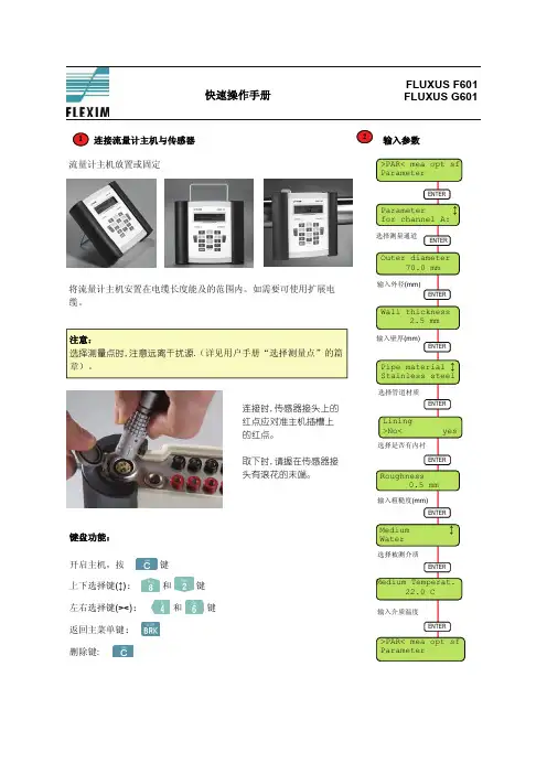
连接流量计主机与传感器
1 流量计主机放置或固定
将流量计主机安置在电缆长度能及的范围内。
如需要可使用扩展电缆。
注意:
选择测量点时,注意远离干扰源.(详见用户手册“选择测量点”的篇
章)。
连接时,传感器接头上的红点应对准主机插槽上的红点。
取下时,请握在传感器接头有滚花的末端。
键盘功能:
开启主机,按
键
上下选择键(↕): 和
键
左右选择键(><): 和 键
返回主菜单键:
删除键:
2 输入参数
3选择输出
:体积流
”
, YES
,也
:
:
A
A
传感器顶部的印记对准呈现一箭头形
表示安装正确。
4开始测量
FLUXUS F601和G601 快速操作手册
A: Volume Flow
测量并输入调整好的传
感器距离值(mm)。
超声波流量计使用说明书一、产品概述超声波流量计是一种通过测量流体中超声波传播速度来确定流量的仪器。
本说明书将详细介绍超声波流量计的使用方法和注意事项。
二、产品参数1. 测量范围:XX至XX(单位)2. 额定压力:XX(单位)3. 额定温度:XX℃4. 精度等级:XX5. 适用介质:XX液体或气体6. 电源要求:XXV AC,50Hz7. 输出信号:模拟信号或数字信号三、安装与接线1. 安装位置:选择一个合适的位置进行安装,确保流速计周围无遮挡物,减少测量误差。
2. 安装方法:根据实际情况选择合适的安装方式,本产品可支持水平、垂直或倾斜安装。
3. 接线步骤:a. 将超声波流量计与电源线连接,确保电源正常供应。
b. 根据需要选择模拟信号输出或数字信号输出,并将对应线缆连接到控制系统或数据采集设备。
四、操作说明1. 打开电源:确保电源供应正常后,打开电源开关,待仪器自检完成后进入工作状态。
2. 参数设置:根据实际需要,在操作界面上进行相应参数配置,包括测量范围、精度等级等。
3. 数据显示:在操作界面上可以实时显示流体的流速、体积流量等相关数据。
4. 报警功能:超声波流量计可设置上下限报警功能,当流速或流量超出设定范围时,会触发报警信号。
5. 数据记录:根据需要,流量计可以将测量数据记录在内部存储器中,或通过通信接口输出给外部设备进行记录和分析。
五、使用注意事项1. 清洁保养:定期对流量计进行清洁保养,避免灰尘或污物对测量精度的影响。
2. 防护措施:避免超声波探头直接暴露在强酸、强碱等腐蚀性介质中,可采取保护套等措施。
3. 避免振动:安装时需防止外部振动对流量计的影响,确保准确测量。
4. 安全操作:操作过程中请勿随意拆卸设备或触碰高压线路,以免发生安全事故。
5. 检定与维修:建议定期对流量计进行检定和维修,确保测量精度和长期稳定性。
六、故障排除在使用过程中,如发现仪器显示异常或无法正常工作,请按以下步骤进行故障排除:1. 检查电源供应是否正常,确保电压稳定。
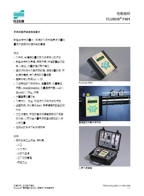
TSFLUXUS_F601V1-1CN-1009- 1 -如有改动, 恕不另行通知.FLUXUS ® 是德国FLEXIM 公司商标, 并受其保护.新型手持式流量计, 快速的外夹式超声波流量测量技术适用于所有种类的管道.特点• 外夹式, 能精确测量双向及快速变化的液体• 新型手持式双声道, 使用方便; 标准配置含多路输入/输出, 内置数据记录及串口• 自动识别探头及其标定数据, 缩短设置时间, 并能提供精确, 持久稳定的测量结果• 锂离子电池可用14个小时• 久经考验的外夹式探头, 其量程宽, 测量管径范围从DN6至DN6500, 测量温度范围从-40℃ 至+400℃; 防尘, 防潮• 内置壁厚测量功能• 外壳防水、防尘, 抗油污及多种液体和污垢• 坚固耐用, 防水等级IP67, 带便携箱并配备各种附件• 双工作模式, 可在时差法和噪音跟踪法之间自动切换, 从而对含大量气泡或固体颗粒的介质也可测量• 在恶劣的条件下能快速安装应用• 用于各类工业场合, 特别是: - 化工- 水及污水- 冷却及空调- 工厂设施管理- 航空工业手持式超声波液体流量计FLUXUS F601管道固定夹具快速安装仪表及便携箱性能指标FLUXUS ®F601TSFLUXUS_F601V1-1CN-1009- -如有改动�, 恕不另行通知.FLUXUS ® 是德国FLEXIM 公司商标, 并受其保护.FLUXUS F601款式手持式测量测量原理时差相关原理, 测量气泡或固体颗粒含量高的介质时可自动切换到噪音跟踪原理流速0.01... 5 m/s重复性0.15% 读数, 视应用而定精度- 体积流量±1% 读数, 视应用而定±0.5% 读数, 经过标定介质所有导声流体 (时差相关原理)主机电源100... 40 V/50...60Hz(主机电源)10.5...15 /V DC(主机上插口)或电池电池锂离子电池, 7. V/4.5 Ah工作时间 (无输出, 输入或背光情况下) > 14 小时功耗< 6 W 通道信号平均0...100 s, 可调测量速率100...1000 Hz响应时间 1 s (单通道), 70 ms 可选材质PA, TPE, AutoTex, 不锈钢防护等级 (根据EN605 9)IP65重量 1.9 kg固定便携管道夹具工作温度-10...+60 ℃显示 x16字符, 点阵, 带背光工作语言英语, 德语, 法语, 荷兰语, 西班牙语测量功能测量量体积流量, 质量流量, 流速, 能量流量累积量体积, 质量, 能量 (可选) 计算功能平均值, 差值, 总和数据记录可记录的参数所有测量量及累积量容量>100,000条测量量FLUXUS ® F601性能指标技术参数TSFLUXUS_F601V1-1CN-1009- -如有改动, 恕不另行通知.FLUXUS ® 是德国FLEXIM 公司商标, 并受其保护.FLUXUS F601通讯接口RS /USB软件软件操作系统(所有Windows TM 版本)FluxData: 下载测量值/记录, 图形显示, 格式转换(例如: Excel TM )FluxKoeff: 生成被测介质参数电缆RS接头RS - USB输出输出与主设备电隔离组数见第4页配件输出适配器 (若输出组数> 4)电流输出范围精度有源输出无源输出0/4... 0 mA0.1%读数±15μA R ext < 200 ΩU ext < 4...16 V, 取决于R ext R ext < 500Ω频率输出范围集电极开路0...10 kHz 4 V/ 4 mA开关量输出光电继电器 作为报警输出 作为脉冲输出 -脉冲值 -脉冲宽度 V/ 100 mA上下限, 流向变化或出错0.01...1000 units 1...1000 ms输入输入与主设备电隔离组数最大4组配件输入适配器 (当输入组数> )温度输入类型连接范围分辨率精度Pt100/Pt10004线-150...+560 ℃0.01 K±0.01%读数±0.0 K电流输入范围精度无源输入无源: - 0...+ 0 mA 0.1%读数±10μA R i =50Ω, P i < 0. W电压输入范围精度内阻0...1 V0.1% 读数±1 mV R i =1 MΩFLUXUS ® F601性能指标F601 标准F601 能量F601 多功能无源电流输出 4开关量输出 温度输入 - 无源电流输入-- 应用 所有液体流量测量含能量计, 可测量BTU 和热量用于复杂测量工作, 如: 泵工作曲线建模配件 - 机箱- 电源, 电线- 电池- 快速管道固定夹具- 串口数据包- 探头固定夹及钢链 (用于M 和Q 探头) - 卷尺- 用户手册, 快速操作指南- 机箱- 电源, 电线- 电池- 快速管道固定夹具- 串口数据包- 探头固定夹及钢链 (用于M 和Q 探头) - 卷尺- 用户手册, 快速操作指南- 机箱- 电源, 电线- 电池- 输出适配器- 输入适配器- 快速管道固定夹具- 串口数据包- 探头固定夹及钢链 (用于M 和Q 探头) - 卷尺- 用户手册, 快速操作指南流量计上端面板 FLUXUS ®F601Technical SpecificationDimensions (in mm)FLUXUS F601Standard Scopes of SupplyF601 StandardF601 EnergyF601Multifunctional422t u p t u o t n e r r u c e v i s s a p 222t u p t u o y r a n i b 22-t u p n i e r u t a r e p m e t 2--t u p n i t n e r r u c e v i s s a p application all flow measurements on liquidsincluding energy calculator for BTU and heat measurementsfor sophisticated measuring tasks, e.g. modeling of pump curves accessories-transport case -power supply, power cable -battery -QuickFix pipe mounting fixture for flowmeter -serial data kit -fastening shoes and chains ( transducer frequency M, Q)-measuring tape -user manual, Quick Start Guide -transport case -power supply, power cable -battery -QuickFix pipe mounting fixture for flowmeter -serial data kit -fastening shoes and chains ( transducer frequency M, Q)-measuring tape -user manual, Quick Start Guide-transport case-power supply, power cable -battery -output adapter -input adapter -QuickFix pipe mounting fixture for flowmeter -serial data kit -fastening shoes and chains ( transducer frequency M, Q)-measuring tape -user manual, Quick Start Guideconnector board at theupper side of the flow-22659213尺寸 (单位: mm)FLUXUS ®F601Technical SpecificationDimensions (in mm)FLUXUS F601Standard Scopes of SupplyF601 StandardF601 EnergyF601Multifunctional 422t u p t u o t n e r r u c e v i s s a p 222t u p t u o y r a n i b 22-t u p n i e r u t a r e p m e t 2--t u p n i t n e r r u c e v i s s a p application all flow measurements on liquids including energy calculator for BTU and heat measurements for sophisticated measuring tasks, e.g. modeling of pump curves accessories -transport case -power supply, power cable -battery -QuickFix pipe mounting fixture for flowmeter -serial data kit -fastening shoes and chains ( transducer frequency M, Q)-measuring tape -user manual, Quick Start Guide -transport case -power supply, power cable -battery -QuickFix pipe mounting fixture for flowmeter -serial data kit -fastening shoes and chains ( transducer frequency M, Q)-measuring tape -user manual, Quick Start Guide -transport case -power supply, power cable -battery -output adapter -input adapter -QuickFix pipe mounting fixture for flowmeter -serial data kit -fastening shoes and chains ( transducer frequency M, Q)-measuring tape -user manual, Quick Start Guide connector board at the upper side of the flow-meter配置FLUXUS ® F601性能指标。
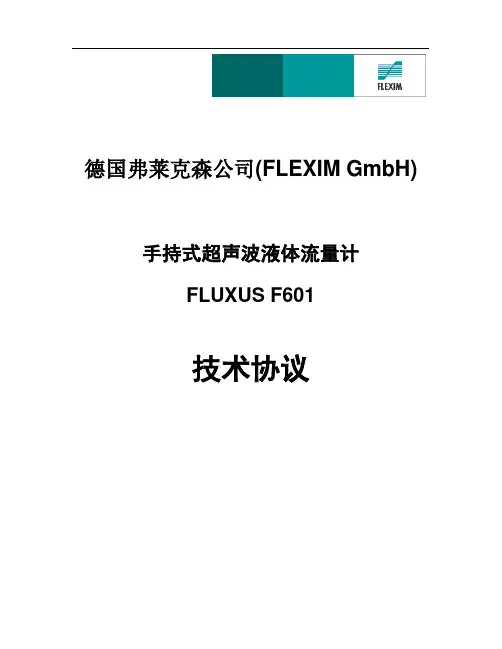
德国弗莱克森公司(FLEXIM GmbH)手持式超声波液体流量计FLUXUS F601技术协议概述本技术协议用于详细说明和规定了制造商根据最终用户提供的技术要求所推荐的仪表技术细节。
所供产品基于工艺参数,在技术性能上完全满足买方工艺参数限定的测量要求。
同时,指明产品的质量保证及售后服务条款。
所有非技术的或超出本技术协议的要求不在供方技术责任范围内。
本技术协议中的所有产品性能指标在各方签署确认后与合同具有同等效力。
应严格遵守,按协议生产供应。
任何超出本协议的供货要求均有可能不被接受。
如由于生产商生产工艺变化而导致供货与本协议不同时,应书面征得买方同意,在确保性能配置不低于原配置并完全满足应用要求时,买方接受该变化,同时,卖方或生产商不得另行收费。
1. 性能指标(整套设备中的主要核心部件)一:手持式超声波液体流量计主机:FLUXUS F601外壳- 重量: 1.9kg- 防护等级: IP65 (根据EN60529)- 材质: 铝合金(内胆)工程塑料(外壳)橡胶(防滑及防撞边框)- 尺寸: (226 x 213 x 59)mm通道: 2 (双通道-标准配置)电源: 锂离子充电电池(7.2V/4.5Ah),外接电源(100~240)VAC 电池工作时间:>14小时(背景灯关闭的情况下)显示: 2 x 16 字符, 点阵, 带背光环境温度: -10℃~+60℃功耗: < 6W信号平均: (0~100)s, 可调测量速率: (100~1000)Hz (1通道)响应时间: 1s (1通道), 70ms可选(可测瞬态流量).测量功能测量量: 体积流量(瞬时量/累积量)质量流量(瞬时量/累积量)流速,声速累积量: 体积,质量计算功能:平均值,总和,差值工作语言: 英语数据记录可记录的参数: 所有测量量及累积量容量: >100,000条测量量通讯接口: 内置RS232通讯接口可通讯的参数: 实测值, 记录值, 参数记录软件: FluxData(随主机套装附带)功能: 下载测量值/记录, 图形显示, 格式转换操作系统:所有Windows 版本过程输出- 输出与主设备电隔离- 标准输出: 2路无源的0/4~20mA电流输出2路开关量输出(光电继电器)过程输入- 输入与主设备电隔离二:常温超声波液体流量传感器-CDM1NZ7(1副)(彩图中大型号传感器)安装方式:管外壁夹装式测量介质:所有导声液体传感器技术:Shear Wave传感器技术适用管径范围:50...3400mm电缆长度: 4米(传感器与电缆线一体化不锈钢铠装)传感器与主机连接接头类型:LEMO接头传感器适用测量温度范围:-30 (130)防护等级:IP67内置SENSPROM传感器永久内存芯片每对传感器均带1瓶高温耦合剂(-30...+130℃,100g/瓶)F601整套设备工程塑料保护箱及部分设备-示意图2. 质量保证制造商保证本合同货物用最好的材料以第一流的工艺制成,全新、未曾用过,在质量与规格一切方面与合同的规定相符(具体配置详见供货范围)。
![景电便携式超声波流量计Fluxus F601[1li]](https://uimg.taocdn.com/a653dd08bed5b9f3f90f1c54.webp)
景电管理局便携式超声波流量计操作规程一、总则为确保景电一、二期总干一泵站电磁流量计长期处于高精度运行状态,定期采用便携式超声波流量计现场比对测量电磁流量计的精度,特制定本规程。
1.本规程规定了便携式超声波流量计进行现场流量测量的接法选择、操作步骤、技术要求、日常维护管理等内容。
2.本规程适用于景电管理局利用便携式超声波流量计与电磁流量计之间的比对工作。
3.本规程依据《JJG1030-2007超声流量计检定规程》和《FLUXUS 601 操作手册》编制而成,规程中所指的便携式超声波流量计型号为Fluxus F601。
二、接法的选择当管径小于或等于800mm,选择“V”字型测法,当管径大于800mm,选择“Z”字型测法。
三、测量点的选择正确选择测量点,所选测量点应避开干扰和涡流这两种对测量精度影响较大的情况,选择有利于声波传输的测量点。
一般选择测量点应满足下列条件:1.避免在水泵、大功率电台、变频,即有强磁场和震动干扰处安装仪表。
2.避开有焊缝、明显凸凹痕迹、积垢、起皮的管路,选择管材应均匀致密,管路没有变形或缺陷的位置。
3.选择距上游10倍直径,下游5倍直径以内均匀直管段没有任何阀门、弯头、变径等干扰流场装置。
4.选择流体为满管的管段。
5.精确选点,无论“V”字型还是“Z”字型接法,都要保证两个测点在被测管道的经过中心线同一平面内的平行线上。
6.选择管道周围要有足够的空间,测量环境干净,便于仪表安装,利于现场人员操作。
四、开机与测量步骤1.安装探头在主机上的 A、B 通道接口,检查探头上是否干净,是否有杂物。
2.长按 ON 键开机,进入操作界面。
3. 按 4、6 键(左右键)左右移动,选择 Parameter(参数设定),按 ENTER(回车)确定。
4. 选择所需要参数设定的通道,按 2、8 键(上下键)更换,按 ENTER(回车) 确定。
5.进入 OUTER DIAMETER(外管直径),输入外管直径数值例如:外管直径为 318mm,直接按 3、1、8 后按下ENTER(回车)确定。
德国FLEXIM便携式超声波流量计F601德国FLEXIM便携式超声波流量计F601探头随仪表成对提供,实流标定后出厂。
所有标定数据、零偏及探头参数全部储存在探头内的永久内存里,与主机连接后,探头将数据发送给主机,主机会自动识别并优化工作。
仪表匹配所连接的探头后,用户只需输入管道和介质参数即可。
同时,仪表内置的数据库提供了大多数常用管材和介质的选项,测量时,用户还可根据状态显示了解应用情况。
高温型便携式超声波流量计的全密封探头及一体式电缆确保长期可靠的工作,探头及电缆铠装层均为不锈钢材质,适用于苛刻的工业环境。
采用独特的双uP技术,高速采样和自适应信号处理技术,即使在苛刻的测量工况下,也能可靠而稳定的工作。
德国FLEXIM便携式超声波流量计F601的产品特点:配夹装式探头和充电电池,是一款理想的服务工具。
探头直接安装在管道外壁上,不受介质影响,安装简便快速,无需切断工艺管道,无需工艺停车,并且无压损,非常适合于测量腐蚀性介质和超纯介质。
以下是德国FLEXIM便携式超声波流量计F601的主要特点:单/双通道便于携带,移动测量适合于科学研究适合于计量标定测厚功能德国FLEXIM便携式超声波流量计F601的技术参数如下:测量原理:时差相关原理流速:0.01~25m/s分辨率:0.025cm/s重复性:0.15%读数,视应用而定精度:(流场充分发展且径向对称)体积流量:±1%读数,视应用而定±0.5%读数,经过标定流速:±0.5%读数,视应用而定可测介质:所有导声流体,且气泡或固体颗粒的体积含量<10%德国FLEXIM便携式超声波流量计F601的主机外壳重量: 1.9kg防护等级:IP65(根据EN60529)材质:铝合金,粉末涂层尺寸:(226x213x59)mm(WxHx D)通道:2危险区:Zone2电源:充电电池(6V/4Ah);外接电源(100~240)VAC电池工作时间:>14h显示:2x16字符,点阵,带背光工作温度:-10~60℃功耗:<6W信号平均:(0~100)s,可调测量速率:(100~1000)Hz(1通道)响应时间:1s(1通道),70ms可选.德国FLEXIM便携式超声波流量计F601的测量功能测量量:体积/质量流量,流速,能量流量(需温度输入)累积量:体积,质量,能量(可选)计算功能:平均值,差值,总和工作语言:捷克语,丹麦语,德语,英语,法语,荷兰语,挪威语,波兰语,西班牙语德国FLEXIM便携式超声波流量计F601的数据记录可记录的参数:所有测量量及累积量容量:>100000条测量量德国弗莱克森手持式超声波流量计F601/G601的探头随仪表成对提供,实流标定后出厂,所有标定数据、零偏及探头参数全部储存在探头的内存里,与主机连接后,探头将数据发送给主机,主机会自动识别并优化工作。
超声波流量计使用说明一、装配1.确保流量计安装在一个水平的位置,以避免测量误差。
二、连接电源和传感器1.将流量计与电源连接,并确保电源的稳定输入。
2.连接传感器到流量计主机上的传感器接口,并确保连接牢固。
三、设置参数1.打开流量计主机,进入设定参数模式。
2.根据实际需求,设置流量计的管道直径、温度范围、压力范围等参数。
3.设置输入和输出方式,包括模拟信号和数字信号。
四、校准1.在流量计中选择校准模式,并选择合适的校准流量。
2.调整光栅设置,确保测量的准确性。
3.对比校准流量和流量计测得流量,调整校准系数,直到两者相等。
五、运行监测1.流量计进入稳定工作状态后,开始对流体进行测量。
2.实时监测流量计所得的流量值,确保测量数据的准确性。
3.警报和故障排除:如果出现异常数据或故障报警情况,需要及时采取措施进行故障排除。
六、维护保养1.定期对流量计进行检查和维护,清除可能存在的污垢或堵塞。
2.检查传感器是否正常工作,及时更换故障传感器。
3.保持流量计的清洁,避免灰尘和杂质进入流量计。
七、注意事项1.在安装和操作流量计时,应注意安全,避免触电、烫伤等事故。
2.在使用过程中,应定期校准流量计,以确保测量准确性。
3.在操作过程中,应注意防水和防尘,避免流量计损坏。
4.在使用过程中,应避免震动和冲击,以免影响测量结果。
总结:超声波流量计是一种高精度、高稳定性的流量测量仪器,使用前需要进行装配、连接电源和传感器、设置参数、校准、运行监测等步骤。
在使用过程中需要注意事项,如注意安全、定期校准、防水和防尘、避免震动和冲击等。
定期维护保养可延长设备寿命,确保测量准确性。
Fluxus F601超声波流量计操作规程1 适用范围:本规程适用于Fluxus F601超声波流量计。
2测量前准备2.1传感器安装点的选择:测量点要尽量选择距上游10倍直径,下游5倍直径以内均匀直管段,没有任何阀门、弯头、变径等干扰流场装置,流体必须为满管。
2.2使用钢卷尺量出被测管路的周长。
计算出被测管路的外管直径。
2.3使用测厚仪量出被测管路的壁厚。
3 开机与测量步骤3.1安装探头在主机上的A、B通道接口,检查探头上是否干净,是否有杂物。
3.2长按ON键开机,进入操作界面。
3.3按4、6键(左右键)左右移动,选择Parameter(参数设定),按ENTER(回车)确定。
3.4选择所需要参数设定的通道,按2、8键(上下键)更换,按ENTER(回车)确定。
3.5进入OUTER DIAMETER(外管直径),输入外管直径数值例如:外管直径为318mm,直接按3、1、8后按下ENTER(回车)确定。
3.6进入WALL THICKNESS(壁厚),输入壁厚数值,按下ENTER(回车)确定。
3.7进入PIPE MATERIAL(管道材质),选择管道材质,按下ENTER(回车)确定。
3.8进入LINING(内衬),选择有无内衬,按下ENTER(回车)确定。
3.9进入RPUGHNESS(粗糙度),选择粗糙度数值(一般经打磨后,打磨设定值粗糙度为0.1),按下ENTER(回车)确定。
3.10进入MEDIUM(介质),选择测量的介质,按下ENTER(回车)确定。
3.11进入MEDIUM TEMPERAT(介质温度),选择介质温度数值,按下ENTER(回车)确定。
3.12进入WAVE INJECTOR(是否需要高温枷具),选择是否需要高温枷具(NO INJECTOR为不需要,IN-400为需要),按2、8键(上下键)更换,按下ENTER(回车)确定。
3.13回车键后,回到Parameter(参数设定)界面,按4、6键(左右键)左右移动,选择Measuring(测试界面),按ENTER(回车)确定。
超声波流量计说明书一、概述超声波流量计是一种高科技的流量测量仪表,它利用超声波在流体中的传播速度与流体流速之间的函数关系来测量流体的流量。
这款流量计具有高精度、高可靠性、易于安装和维护等优点,特别适合用于各种工业生产过程中的流量测量。
二、产品特点1. 高精度:超声波流量计采用先进的信号处理技术和算法,能够实现高精度的流量测量,有效避免了传统流量计在测量过程中可能出现的误差。
2. 宽测量范围:超声波流量计适用于各种流速和流量范围,能够满足不同用户的需求。
无论是小流量还是大流量,它都能准确地测量出流体的流量。
3. 无压力损失:超声波流量计在测量过程中对流体没有任何阻碍,因此不会对流体产生压力损失,从而保证了流体的流动性能。
4. 稳定性好:超声波流量计的测量部件采用高品质的材料和工艺制作,保证了长期使用的稳定性和可靠性,大大减少了维护和维修的频率。
5. 易于安装和维护:超声波流量计的安装非常简便,只需要按照说明书的要求进行安装即可。
同时,它的维护也非常方便,只需要定期清洗测量管路和检查各部件是否正常工作即可。
三、使用方法1. 安装前准备:在安装超声波流量计之前,需要先确认测量管路已经清洗干净,没有任何杂质和污垢。
同时,需要检查流量计的型号和规格是否符合要求,并检查电源和信号线是否连接正常。
2. 安装方式:根据现场的实际情况,选择合适的安装方式。
一般来说,超声波流量计的安装方式有插入式、管段式等。
按照安装说明书的步骤进行安装,确保安装牢固可靠。
3. 参数设置:根据流体类型、管道材质和尺寸等参数设置流量计的测量参数。
这些参数的设置将直接影响到测量结果的准确性和可靠性,因此需要按照说明书的要求正确设置各项参数。
4. 校准和调试:在安装完成后,需要对超声波流量计进行校准和调试,以确保其测量准确度和稳定性符合要求。
一般来说,校准和调试需要在专业人员的指导下进行。
5. 日常维护:为了保持超声波流量计的测量精度和使用寿命,需要定期对其进行检查和维护。