LWQ系列气体涡轮流量计使用手册
- 格式:pdf
- 大小:949.97 KB
- 文档页数:16
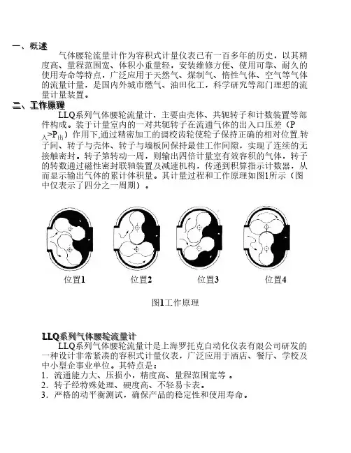
(产品管理)LWQ系列气体涡轮流量计产品说明书-无纸记录仪有纸记录□燃气计量专用仪表□油气回收系统专用仪表□始动流量低,可达0.5m3/h,适合贸易结算□高精确度,壹般可达±1.5%R、±1.0%R□重复性好,短期重复性可达0.05%-0.2%□温度、压力实时补偿,直接显示标准状态下流量概述——————————————LWQ型气体涡轮流量传感器是吸取了国内外流量仪表先进技术经过优化设计,综合了气体力学、流体力学、电磁学等理论而自行研制开发的新壹代高精度、高可靠性的气体精密计量仪表,具有出色的低压和高压计量性能,多种信号输出方式以及对流体扰动的低敏感性,广泛适用于天然气、煤制气、液化气、轻烃气等气体的计量。
该类涡轮流量产品本身不具备现场显示功能,仅将流量信号以脉冲信号的方式远传输出。
仪表价格低廉,集成度高,体积小巧,特别适用于和二次显示仪、PLC、DCS等计算机控制系统配合使用。
该类涡轮流量计均为防爆产品,防爆等级为:ExdIIBT6。
产品特点——————————————·优质合金涡轮,具有更高的稳流和耐腐蚀作用·进口优质专用轴承,使用寿命长·计量室和通气室隔绝,保证了仪表的安全性·流量范围宽(Qmax/Qmin≥20:1),重复性好,精度高(可达1.0级),压力损失小,始动流量低,可达0.6m3/h·仪表具有防爆及防护功能,防爆标志为ExdⅡBT6、ExiaⅡCT6,防护等级为IP65技术参数——————————————2.测量范围及工作压力公称通径型号标准量扩展耐压安装方式DN25 LWQ-25□——W3 0.5-4 4.0 法兰(螺纹)——W4 0.7-7 4.0——W5 1.5-15 4.0S1 3-30 W1 1.5-30 4.0S2 4-40 W2 2-40 4.0DN40 LWQ-40□S1 5-50 W1 2.5-50 4.0 法兰(螺纹)S2 8-80 W2 4-80 4.0DN50 LWQ-50□S1 10-100 W1 5-100 4.0 法兰S2 15-150 W2 8-150 4.0 法兰DN65 LWQ-65□S 15-200 W 10-200 1.6 法兰DN80 LWQ-80□S 15-300 W1 10-300 1.6 法兰W2 15-350 1.6 法兰DN100 LWQ-100□S 20-400 W1 15-400 1.6 法兰W2 20-500 1.6 法兰DN125 LWQ-125□S 20-800 W1 18-800 1.6 法兰W2 20-900 1.6 法兰DN150 LWQ-150□S 50-1000 W1 25-1000 1.6 法兰W2 50-1200 1.6 法兰DN200 LWQ-200□S 150-2000 W 80-2500 1.6 法兰DN250 LWQ-250□S 200-3000 W 150-3500 1.6 法兰DN300 LWQ-300□S 250-4000 W 200-4000 1.6 法兰仪表分类——————————————1.按仪表功能分类LWQ系列气体涡轮流量计可分为3大类,即:□气体涡轮流量传感器/变送器□智能壹体化气体涡轮流量计□智能温压补偿壹体化气体涡轮流量计2.功能说明■气体涡轮流量传感器/变送器该类涡轮流量产品本身不具备现场显示功能,仅将流量信号远传输出。
□燃气计量专用仪表□油气回收系统专用仪表□始动流量低,可达0.5m3/h,适合贸易结算□高精确度,一般可达±1.5%R、±1.0%R□重复性好,短期重复性可达0.05% - 0.2%□温度、压力实时补偿,直接显示标准状态下流量概述——————————————LWQ型气体涡轮流量传感器是吸取了国内外流量仪表先进技术经过优化设计,综合了气体力学、流体力学、电磁学等理论而自行研制开发的新一代高精度、高可靠性的气体精密计量仪表,具有出色的低压和高压计量性能,多种信号输出方式以及对流体扰动的低敏感性,广泛适用于天然气、煤制气、液化气、轻烃气等气体的计量。
该类涡轮流量产品本身不具备现场显示功能,仅将流量信号以脉冲信号的方式远传输出。
仪表价格低廉,集成度高,体积小巧,特别适用于与二次显示仪、PLC、DCS等计算机控制系统配合使用。
该类涡轮流量计均为防爆产品,防爆等级为:ExdIIBT6。
产品特点——————————————·优质合金涡轮,具有更高的稳流和耐腐蚀作用·进口优质专用轴承,使用寿命长·计量室与通气室隔绝,保证了仪表的安全性·流量范围宽(Qmax/Qmin≥20:1),重复性好,精度高(可达1.0级),压力损失小,始动流量低,可达0.6m3/h·仪表具有防爆及防护功能,防爆标志为ExdⅡBT6、ExiaⅡCT6,防护等级为IP65技术参数——————————————1.基本参数:表1仪表口径及连接方式25、40、50、80、100、150、200、250采用法兰连接25、40可采用螺纹连接精度等级±1.5%R、±1%R量程比1:10;1:20;1:30仪表材质表体:304不锈钢;叶轮:防腐ABS或优质铝合金;转换器:铸铝被测介质温度(℃)-30℃~+80℃环境条件介质温度:-30℃~+80℃,相对湿度5%~90%,大气压力86~106Kpa输出信号三线制脉冲频率信号,低电平≤0.8V 高电平≥8V供电电源+12VDC 、+24VDC(可选)信号传输线STVPV3×0.3传输距离≤1000mLWQ系列气体涡轮流量计LWQ gas tuibine flow meter信号线接口内螺纹M20×1.5防爆等级ExdIIBT6防护等级IP652.测量范围及工作压力注1:表2中“标准量程”中标示的测量范围为通用测量范围;(即适用于:LWQ-N/A/B/C/D)表2 公称通径型号标准量扩展耐压安装方式DN25 LWQ-25□——W3 0.5-4 4.0 法兰(螺纹)——W4 0.7-7 4.0——W5 1.5-15 4.0S1 3-30 W1 1.5-30 4.0S2 4-40 W2 2-40 4.0DN40 LWQ-40□S1 5-50 W1 2.5-50 4.0 法兰(螺纹)S2 8-80 W2 4-80 4.0DN50 LWQ-50□S1 10-100 W1 5-100 4.0 法兰S2 15-150 W2 8-150 4.0 法兰DN65 LWQ-65□S 15-200 W 10-200 1.6 法兰DN80 LWQ-80□S 15-300 W1 10-300 1.6 法兰W2 15-350 1.6 法兰DN100 LWQ-100□S 20-400 W1 15-400 1.6 法兰W2 20-500 1.6 法兰DN125 LWQ-125□S 20-800 W1 18-800 1.6 法兰W2 20-900 1.6 法兰DN150 LWQ-150□S 50-1000 W1 25-1000 1.6 法兰W2 50-1200 1.6 法兰DN200 LWQ-200□S 150-2000 W 80-2500 1.6 法兰DN250 LWQ-250□S 200-3000 W 150-3500 1.6 法兰DN300 LWQ-300□S 250-4000 W 200-4000 1.6 法兰仪表分类——————————————1.按仪表功能分类LWQ系列气体涡轮流量计可分为3大类,即:□气体涡轮流量传感器/变送器□智能一体化气体涡轮流量计□智能温压补偿一体化气体涡轮流量计2.功能说明■气体涡轮流量传感器/变送器该类涡轮流量产品本身不具备现场显示功能,仅将流量信号远传输出。
LW系列涡轮流量仪表产品使用说明书目录一、概述 (2)二、 LWBY型液体涡轮流量传感器 (2)三、LWBY型液体涡轮流量变送器 (8)四、LWBY型现场显示涡轮流量计 (9)五、运输、贮存 (11)六、开箱及检查 (11)七、订货须知 (11)八、常见故障和排除 (12)LW系列涡轮流量仪表一、概述LW系列涡轮流量仪表包括LWGY型液体涡轮流量传感器、LWBY型液体涡轮流量变送器和LWSY型现场显示涡轮流量计等,属于速度式流量仪表。
本系列仪表适用于清洁或基本清洁的单项液体的测量,单独或相关设备配套,可用来测量封闭管道中的体积流量或总量。
具有结构简单、轻巧、精确度高、复现性好、反应灵敏、安装维护使用方便等特点,广泛应用于石油、化工、供水、食品、制药及科研试验等行业,是流量计量和节能的理想仪表。
二、LWGY型液体涡轮流量传感器LWGY型液体涡轮流量传感器是LW系列涡轮流量仪表中的基本产品,它将管道中液体的流量转换成电脉冲信号、并经过显示仪表或计算机系统处理来完成对管道中液体流量的测量或总量计量。
1结构特征与工作原理1.1结构特征:传感器主要有传感组件、信号检测器和放大器组成,(见图1)。
其轴承系统为硬质合金,提高耐磨性、保证产品精度;其中:放大器分两线制和三线制两处形式。
1.2工作原理当流体流经仪表时,推动表内叶轮旋转,然后通过叶轮与信号检测器之间的磁耦合,将流体的流速转换为电脉冲信号输出,通过放大器放大整形并传输给显示仪表,即达到对流体的体积流量或总量的测量目的。
在一定的流量范围内,脉冲频率f与流经传感器的液体的体积流量Q成正比。
流量方程式为:Q=f/K式中:f—脉冲频率K—传感器的仪表系数【1/L】由“校验单”给出。
2.基本参数及性能标准2.1本传感器执行专业标准(JB/T9246-1999涡轮流量传感器)2.3 使用环境:环境温度 -20~+55℃相对温度 5%~95%大气压力 86~106Kpa2.4被测流体温度普通型 -20~+120℃防爆型 -20~70℃2.5 防爆标志:dⅡBT52.6 输入信号:两线制输出输出低电平I≈3mAOL≈13mA(方波)输出高电平IOH负载电阻R(包括线路阻抗)在100~500Ω范围内(根据所配置的显示仪表或其它接收装置输入信号的要求,选择合适的R值.)三线制输出:V≥5V (方波)OP-P2.7电源供电两线制:+24VDC三线制:+12VDC~+24VDC2.8传输距离:1Km3.连接结构及尺寸:3.1 螺纹连接结构见图2,连接尺寸见表23.2 法兰连接结构见图3,连接尺寸见表2法兰结构及尺寸执行(JB79-59,JB81-59,JB82-59)标准.4.安装通常情况下传感器应为水平安装,正常的管线配置如图41.入口2.阀门3.过滤器4.消气器5.整流器6.涡轮流量传感器7.后直管段8.旁通管段图4 系统配置图图中各部分的作用分述如下:消失器:用来消除流体中的游离气体,避免游离气体占有的体积造成测量误差。
LWGY基本型涡轮番量传感器(LWGYA型涡轮番量变送器)(LWGYB型涡轮番量计)(LWGYC型涡轮番量计)使用说明书目录一、概括02二、 LWGY基本型涡轮番量传感器02三、 LWGYA型涡轮番量变送器07四、 LWGYB型涡轮番量计08五、 LWGYC型涡轮番量计09六、 LWGYD型涡轮番量计09七、维修和常有故障22八、运输、储存22九、开箱注意事项22十、订货须知23一、概括LWGY 系列涡轮番量传感器 (以下简称传感器) 鉴于力矩均衡原理, 属于速度式流量仪表。
传感器拥有构造简单、轻盈、精度高、复现性好、反响敏捷,安装保护使用方便等特色。
宽泛用于石油、化工、冶金、供水、制药、环保等行业。
传感器与显示仪表配套使用,合用于丈量关闭管道中无腐化,无纤维、颗粒等杂质,粘度-6 2小于 5× 10 m/s 的液体介质。
二、 LWGY 基本型涡轮番量传感器1.工作原理液体介质流经传感器壳体, 因为叶轮的叶片与流向形成特定的角度, 流体的冲力使叶片拥有转动力矩, 战胜摩擦力矩和流体阻力以后叶片旋转, 在力矩均衡后转速稳固,转速与流速成正比,因为叶片有导磁性,它处于信号检测器的磁场中, 旋转的叶片切割磁力线, 周期性的改变着线圈的磁通量, 进而使线圈两头感觉出电脉冲信号。
信号经过放大器的放大整形, 形成有必定幅度的连续的矩形脉冲波, 可传输至显示仪表, 显示出流体的刹时流量或总量。
在必定流量范围内, 脉冲频次 f 与流经传感器的流体的刹时流量 Q 成正比,流量方程为:Q 3600fk式中:f ——脉冲频次 [Hz] ;k——传感器的仪表系数[1/m 3] 或 [1/L] ;Q ——流体的刹时流量 3或 [L/h] ;[m /h] 3600 ——换算系数;每台传感器的仪表系数 k 略有不一样, 这是由制造厂家经过流量装置实流校验得出,打印于合格证书中。
2.基本参数LWGY □LWGYLWGYA类 型LWGYBLWGYC公 称 通径□□ 说 明基本型: 12VDC 供电,脉冲信号输出,高电平≥ 8V 、 低电平≤。
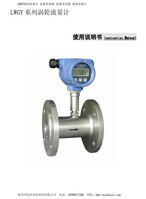
LWGY系列涡轮流量计使用说明书lnstruction Manual目录LWGY系列涡轮流量计说明书(1-14)一、概述 (2)二、产品特点 (2)三、工作原理 (2)四、主要技术参数………………………………………………3-4五、外形尺寸……………………………………………………4-6六、安装要求……………………………………………………6-7七、使用要求……………………………………………………7-8八、LWGYA型涡轮流量传感器介绍 (8)九、LWGYB型涡轮流量计介绍 (9)十、LWGYC型涡轮流量计介绍 (9)十一、LWGYD型涡轮流量变送器介绍..............................10-11 十二、LL-05型智能流量积算器操作说明........................12-14 十三、维修和常见故障 (15)十四、运输、储存 (15)十五、开箱注意事项 (16)十六、订货须知 (16)十七、使用期限 (16)插入式流量计说明书(15-27)一、概述 (17)二、产品特点 (18)三、原理及基本公式 (18)四、主要参数……………………………………………………18-20五、结构及各零件名称(B型)…………………………………20-23六、确定传感器仪表系数KDS的方法…………………………23-24七、维修 (24)八、配套显示仪表………………………………………………24-28九、一般故障及排除方法………………………………………28-30十、保修 (30)一、概述LWGY 涡轮流量计是本厂采用国外先进技术生产制造的,是液体计量最理想的流量计之一。
它具有结构简单、精确度高、安装维修使用方便等特点。
该产品广泛用于石油、化工、冶金、供水、造纸、环保、食品等领域,可靠测量水、纯水、自来水、无杂质的污水、柴油、汽油和低粘度的原油等液体的体积流量。
与具有定量功能的显示仪表配套使用,可以进行自动定量控制、上下限报警等用途。

LWGQ Gas turbine flowmeter使用说明书湖北南控仪表科技有限公司(鄂H制00000124号)1.The generalizabilityLWGQ series gas turbine flowmeter is learned the flow meter at home and abroad advanced technology optimized design, the comprehensive gas mechanics, fluid mechanics, electromagnetism theory by itself to set temperature, pressure, flow sensor is developed and in the integration of intelligent flow totalizer.especially for a new generation of high precision, high reliability gas precision measuring instrument, has a good performance of low pressure and high pressure measurement, multiple way signal output and low sensitivity to the fluid disturbance, is widely used in natural gas, coal gas, liquefied gas and light hydrocarbon gas and gas metering.According to the product by the national anti-explosive products quality inspection department GB3836.2000 the explosive gas environment with electrical equipment part 1: general requirements ", GB3836.2-2000 "explosive gas environment with electrical equipment part 2: flameproof" d ", "and GB3836.4-2000" explosive gas environment with electrical equipment part 4: "I" intrinsically safe "standard inspection, explosion-proof marks for Exd ⅡBT6 (flameproof), Exia ⅡCT6 (Ann). Applicable to contain A and B ⅡⅡ, ⅡC T1 ~ T4 explosive gas mixture temperature classes 0 (only this type) 1, 2, area for the dangerous sites.2.Product features⏹High quality alloy turbine, have higher steady flow and corrosion effect⏹Imported high quality bearing, long service life⏹Measuring room from ventilation chamber, guarantee the safety of the instrument⏹Can be detected by measuring the temperature, pressure, and flow of the gas, can flow automatic trackingcompensation, and displays a standard condition (Pb = 101.325 KPa, Tb = 101.325 K) of gas volume cumulant; Can be real-time query temperature and pressure values⏹Wide range of flow rate (Q max/Q min≥20:1), good repeatability, high precision (up to 1.0), small pressure loss,initiating flow rate is low, can reach 0.6m3/h⏹Intelligent instrument coefficient more nonlinear correction⏹Built-in pressure, temperature sensors, high safety performance, compact structure, beautiful shape⏹Instruments with explosion protection and protective functions, marks for Exd ⅡBT6, Exia ⅡCT6, protectiongrade reaches IP65⏹System low power consumption, section 3.2 V10AH lithium batteries can be use more than 3 years in a row⏹Instrument coefficient, the cumulative flow value power lost decade is not lost3. The working principle ofWhen the fluid flows into the flow of time, under the action of air inlet special-purpose integrated rectifier rectifier and accelerate, due to the turbine blades and the direction of flow at an Angle, the turbine rotational torque, after overcoming friction torque and fluid resistance moment, the turbine to spin. Within the scope of a certain flow, turbine rotating angular velocity is proportional to the fluid volume flow. According to the principle of electromagnetic induction, the use of magnetic sensor signal from coaxial rotation during induction out with fluid volume flow is proportional to the pulse signal, the signal after amplification, filtering, plastic with temperature and pressure sensor signal into micro processing unit of intelligent flow totalizer.especially for processing, and the volume of a gas flow rate and total directly display on the LCD screen.4.Technical parameters:4.1 The basic parameters:4.1.1Table 1specifications Nominal diameter(mm)Flow range(m3/h)Pick up traffic(m3/h)Pressure of work(MPa)Type of installationLWGQ-25 25 (1") 2.5-25 0.6 4.0 Flange (thread)LWGQ-40 40(1.5")5-50 0.8 4.0 Flange (thread)LWGQ-50 50(2")10-100 1 4.0 FlangeLWGQ-80 80(3")20-400 2.5 1.6 FlangeLWGQ-100 100(4") 32-650 2.5 1.6 FlangeLWGQ-150 150(6")50-1000 4 1.6 FlangeLWGQ-200 200(8")130-2500 8 1.6 FlangeLWGQ-250 250(10")200-4000 12 1.6 FlangeLWGQ-300 300(12") 320-6500 16 1.6 Flange4.1.2 Level of accuracy: 1.0, 1.54.1.3Conditions of use:◆The environment temperature:-30℃~+60℃;◆The atmospheric pressure:86KPa~106KPa;◆Medium temperature:-30℃~+80℃;◆Relative humidity:5%~95%4.2Electrical performance indicators:Table 2specifications Display and output Power supply LWGQ- N Low voltage pulse level 1 v or less, high level 5 v, or three wire system External power DC12V-24VLWGQ-A (4 ~ 20 mA) standard linear analog signal corresponds to (0 ~ Qmax) m3 / h standardvolume flow, two wire systemExternal power DC24VLWGQ-B With multipoint correction precision, at the same time show the instantaneous flow andcumulative flow double row liquid crystal display (LCD), as follows:Q XXXX Four instantaneous flow rate(m3/h)XXXXXXXX Eight cumulative flow(m3)Note: the total flow rate since 00.000000 counting, automatic expanding display precision,maximum down to 999999.99. Accumulative total flow rate value can be zero, instrumentcoefficient, the cumulative flow value power lost decade is not lost.3.2 V10AH lithium batteriesLWGQ-C In LWGQ - B (the scene display type) on the basis of adding 4-20 madc current output External power DC24VLWGQ-D In LWGQ - B (the scene display type) with temperature and pressure sensors, flow forautomatic compensation correction arithmetic for different condition. Can query, such astemperature, pressure, battery at the same time. Can output high frequency, low frequencyvoltage pulse signal, and 4-20 madc two wire current signal.3.2 V10AH lithium battery orDC24V power supply4.3Model system:Table 3Model Explain LWGQ □□□Meter Type N Basic, pulse outputA Current output typeB The display typeC Display output type (scene shows + current output)D Temperature, pressure compensation typeMeter diameter25 25mm 40 40mm 50 50mm 65 65mm 80 80mm 100 100mm 150 150mm 200 200mm 250 250mm 300 300mmSensor material NBasic material, high quality aluminum alloy. (the highest pressure: 1.0MPa)S Stainless steel material. (high pressure anti-corrosion type)For example, the model is: LWGQ - C - 50 s of the gas turbine flowmeter, said:Meter diameter of 50 mm, display, output way of live shows, output current sensor is made of stainless steel high pressure gas turbine flow meter.5.Overall dimensionsFlow meter appearance is shown in figure 1, the specific sizes are shown in table4Figure 1Note : as shown in figure 1 as temperature pressure compensation type instrument appearance. With all the model instrument sensor part of the machine and high caliber size.Table 4Model Nominaldiameter mm L D H K n d Bolt specification Conventional pressure MPaLWGQ-25 25 150 115 236 85 4 φ14 M12×50 4.0LWGQ-40 40 150 150 266 110 4 φ18 M16×55 LWGQ-50 50 150 165 285 125 4 φ18 M16×60 LWGQ-65 65 240 185 300 145 4 φ18 M16×65 1.6LWGQ-80 80 240 200 319 160 8 φ18 M16×70 LWGQ-100 100 300 220 337 180 8 φ18 M16×80 LWGQ-150 150 450 285 395 240 8 φ22 M20×80LWGQ-200 200 500 340 448 295 12 φ22 M20×90 LWGQ-250 250 500 403 495 355 12 φ26 M24×90 LWGQ-30030050046054841012φ26M24×1006.Selection of flowmeter6.1 When users in the selection, should according to the nominal pipe pressure, medium to high pressure, medium temperature, medium composition, flow range and signal output requires reasonable selection of flowmeter type specification.6.2 In order to make the use of the flowmeter performance is the best, the use of the flowmeter flow range should be within the scope of Qmax (20% ~ 20%) is more appropriate.6.3 Meter factory of signal output mode: working condition of the pulse signal output (three-wire system), the standard traffic signal output or RS - 485 communication (IC) output. If you want have other output function, when ordering, please .6.4 Selection of instanceKnown to the actual working pressure of a gas pipeline pressure) (table 0.8 MPa to 1.2 MPa, mediumtemperature range is 5 ℃ ~ + 40 ℃, the throughput of 3000 ~ 8000 nm3 / h (standard of traffic), without taking into consideration under the condition of gas composition, requirement of the specifications of the flowmeter.Analysis: the description given in table 1 flow range for the working condition of flow range, and in this case theflow range is given in the standard condition flow range, therefore, must according to the gas side Mr. Cheng will flow in the conversion of flow condition, and then choose the appropriate diameter. Gas equation is as follows : 2Z gb bb bF C Q =ZZ T P T P Q =Q······ Type in the :Q b —— Standard of flow ,m 3/h ;Q —— Working condition of traffic ,m 3/h ;C * —— Scaling factor. (look-up table, a table is only for type selection reference when conversion)gbz Z Z =F —— Gas compressibility factor, according to China national petroleum corporation SY/T 6143-1996 standard.The data in table b is for reference only, the data according to the true relative density of natural gas Gr = 0.600, nitrogen and carbon dioxide mole fraction were calculated as 0.00, when the medium pressure below 0.5 MPa, Zb/deal in mid-december, = 1.00 estimate. Calculation ::① when the pressure of the medium low temperature (0.8 MPa), high (+ 40 ℃) when (in the gas peak), should have the biggest case volume flow (can not consider the effect of FZ, model selection of the local atmospheric pressure of 101.325 kPa):Namely 965.472=293.1540+273.15×800+101.325101.325×8000=T T ·P P Q =Q b b maxb max m 3/h Estimation of or use the following formula (type, C * as the conversion factor, check appendix table a):960.38=8.338000=C Q =Q bmax max m 3/h ② Medium pressure was highest (1.2 MPa), the lowest temperature (5 ℃) (in gas trough), should have aminimum standard of volume flow :Namely 213.51=293.155273.15×1200+101.325101.325×3000=Q min m 3/hEstimation of or use the following formula : 214.3=14.03000=C Q =Q bmin min m 3/h Selection :learn from the above estimates that want to choose the flowmeter its working flow range is (213.5 ~ 965.472m3 / h), by table 1 check, choose the meter models for LWGQ - 150.According to the gas equation of scaling factor C * valuesTable aC * P T MPa0.01 0.05 0.10 0.15 0.20 0.25 0.30 0.35 0.40 0.45 0.50 0.55 0.60 0.65(℃)-20 1.27 1.70 2.30 2.87 3.34 4.02 4.59 5.16 5.73 6.30 6.87 7.44 8.02 8.59 -15 1.25 1.70 2.26 2.82 3.38 3.94 4.50 5.06 5.62 6.18 6.74 7.30 7.86 8.42 -10 1.22 1.66 2.21 2.76 3.31 3.86 4.41 4.96 5.51 6.60 6.61 7.16 7.71 8.26 -5 1.20 1.63 2.17 2.71 3.25 3.79 4.33 4.87 5.41 5.95 6.49 7.03 7.57 8311 0 1.18 1.60 2.13 2.66 3.19 3.72 4.25 4.78 5.31 5.84 6.37 6.90 7.43 7.96 51.16 1.572.09 2.613.13 3.654.17 4.695.21 5.736.25 6.777.29 7.81 10 1.14 1.55 2.06 2.57 3.08 3.59 4.10 4.61 5.12 5.63 6.14 6.66 7.17 7.68 15 1.12 1.52 2.02 2.52 3.03 3.53 4.03 4.53 5.03 5.54 6.04 6.54 7.04 7.54 20 1.10 1.49 1.99 2.48 2.97 3.47 3.96 4.45 4.95 5.44 5.93 6.43 6.92 7.42 25 1.08 1.47 1.95 2.44 2.92 3.41 3.89 4.38 4.86 5.35 5.84 6.32 6.81 7.29 30 1.06 1.44 1.92 2.40 2.88 3.35 3.83 4.31 4.78 5.26 5.74 6.22 6.69 7.17 35 1.05 1.42 1.89 2.36 2.83 3.30 3.77 4.24 4.71 5.18 5.65 6.12 6.58 7.05 40 1.03 1.40 1.86 2.32 2.78 3.25 3.71 4.17 4.63 5.095.566.02 6.48 6.9445 1.01 1.38 1.83 2.29 2.74 3.19 3.65 4.10 4.56 5.01 5.47 5.92 6.38 6.83 50 1.00 1.35 1.80 2.25 2.70 3.15 3.59 4.04 4.49 4.94 5.38 5.83 6.28 6.73C* T P MPa0.70 0.75 0.80 0.85 0.90 0.95 1.00 1.20 1.40 1.60 2.00 2.50 3.00 4.00(℃) -20 9.16 9.73 10.3 10.9 11.4 12.0 12.6 14.9 17.2 19.4 24.0 29.7 35.4 46.9 -15 8.98 9.54 10.1 10.7 11.2 11.8 12.3 14.6 16.8 19.1 23.6 29.1 34.8 46.0 -10 8.81 9.36 9.91 10.5 11.0 11.6 12.1 14.3 16.5 18.7 23.1 28.6 34.1 45.1 -5 8.65 9.19 9.72 10.3 10.8 11.3 11.9 14.0 16.2 18.4 22.7 28.1 34.5 44.3 0 8.49 9.20 9.55 10.1 10.6 11.1 11.7 13.8 15.9 18.0 22.3 27.6 32.9 43.4 5 8.33 8.86 9.38 9.90 10.4 10.9 11.5 13.5 15.6 17.7 21.9 27.1 32.3 42.1 10 8.19 8.70 9.21 9.72 10.2 10.7 11.3 13.3 15.3 17.4 21.5 26.6 31.7 41.9 15 8.05 8.55 9.05 9.55 10.1 10.6 11.1 13.1 15.1 17.1 21.1 26.1 31.1 41.2 20 7.91 8.40 8.90 9.39 9.88 10.4 10.9 12.8 14.8 16.8 20.7 25.7 30.6 40.5 25 7.78 8.26 8.75 9.23 9.72 10.2 10.7 12.6 14.6 16.5 20.4 25.2 30.6 39.8 30 7.65 8.12 8.60 9.08 9.56 10.0 10.5 12.4 14.3 16.2 20.1 24.8 30.1 39.1 35 7.52 7.99 8.46 8.93 9.40 9.87 10.3 12.2 14.1 16.0 19.7 24.4 29.6 38.5 40 7.40 7.87 8.33 8.79 9.25 9.71 10.3 12.0 13.9 15.7 19.4 24.0 29.1 37.9 45 7.29 7.47 8.20 8.65 9.11 9.56 10.3 11.8 13.7 15.5 19.1 23.7 28.6 37.3 50 7.17 7.62 8.07 8.52 8.96 9.11 9.86 11.7 13.4 15.2 18.8 23.3 27.8 36.7Note::1.The value in the table to the local atmospheric pressure of 101.325 KPa to calculate;2.Pressure for the tableFz values of gas compressibility factorTable a tFz ℃)P(M P a)-20 -15 -10 -5 0 5 10 15 20 250.50 1.0088 1.0083 1.0078 1.0073 1.0069 1.0065 1.0061 1.0058 1.0054 1.00511.00 1.0180 1.0169 1.0159 1.0149 1.0140 1.0132 1.0124 1.0117 1.0110 1.01031.50 1.0276 1.0258 1.0242 1.0227 1.0213 1.0200 1.0188 1.0176 1.0166 1.01562.00 1.0375 1.0351 1.0328 1.0307 1.0287 1.0269 1.0252 1.0237 1.0222 1.02092.50 1.0479 1.0446 1.0416 1.0389 1.0363 1.0340 1.0318 1.0298 1.0280 1.02633.00 1.0587 1.0546 1.0508 1.0473 1.0441 1.0412 1.0385 1.0360 1.0337 1.03163.50 1.0700 1.0649 1.0602 1.0560 1.0521 1.0485 1.0453 1.0423 1.0396 1.03704.00 1.0818 1.0756 1.0699 1.0648 1.0602 1.0506 1.0521 1.0486 1.0454 1.04254.50 1.0941 1.0866 1.0799 1.0739 1.0685 1.0635 1.0591 1.0550 1.0513 1.04795.00 1.1069 1.0980 1.0902 1.0831 1.0768 1.0712 1.0660 1.0614 1.0571 1.05335.50 1.1201 1.1089 1.1006 1.0926 1.0853 1.0789 1.0730 1.0678 1.0630 1.05876.00 1.0339 1.1218 1.1113 1.1021 1.0939 1.0866 1.0800 1.0741 1.0688 1.06406.50 1.0480 1.1342 1.1222 1.1117 1.1025 1.0943 1.0870 1.0805 1.0746 1.06937.00 1.1624 1.1467 1.1332 1.1214 1.1111 1.1020 1.0943 1.0867 1.0803 1.07457.50 1.1770 1.1593 1.1442 1.1311 1.1197 1.1097 1.1008 1.0929 1.0859 1.07968.00 1.1917 1.1719 1.1551 1.1407 1.1282 1.1172 1.1075 1.0990 1.0913 1.08457.Install and use7.1 The installation of the flowmeter • Before installation, the pipe must purge clean to prevent residual iron affect the normal operation of flowmeter. •Before installation, the use of tiny air blows the turbine, the turbine can flexible rotation, no random noise, counter rotating is normal, uninterrupted card lag phenomenon, the flowmeter can be used to install. • Flow meter in the middle of the flange and pipe flanges to add sealing washer.•Meter shall be equipped with filters, temperament is dirty places should be equipped with oil filter, before you place an order, can order to me at the same time, it is strictly prohibited to filter and flowmeter directly connected. • Meter shall be added by the valve before, during, and after installation. • Flange joint pipe Canon place there should be no protrusions.•Flow meter installed, it is strictly prohibited in the import and export directly for welding flange, so as not to burn out flowmeter internal parts. •Meter should be installed in easy maintenance, strong electromagnetic interference and mechanical vibration and thermal radiation effects ; •Flowmeter is unfavorable with frequent interruptions in the flow and strong pulsation flow or pressure pulsation of the occasion ; •Flow meter outdoor installation, should be the upper cover, to prevent rain water immersion and strong sunlight affect the service life of the meter ; •Flow meter can be installed in horizontal or vertical, the fluid flow direction should be consistent with the direction of the logo on the shell, should guarantee the upstream of the flow meter is not less than 10 dn straight pipe, after the table is not less than 5 dn straight pipe. •In order not to affect the normal fluid transportation, it is suggested that according to the figure 2 by-pass pipe installation, must close the by-pass pipe valve when normal use.tFz ℃)P (M P a )30 35 40 45 50 55 60 65 70 75 0.50 1.00481.0046 1.0043 1.0041 1.0039 1.0036 1.0034 1.0032 1.0031 1.0029 1.00 1.0097 1.0092 1.0087 1.0082 1.0077 1.0073 1.0069 1.0065 1.0061 1.0058 1.50 1.0147 1.0138 1.0130 1.0123 1.0116 1.0109 1.0103 1.0097 1.0091 1.00862.00 1.0197 1.0185 1.0174 1.0164 1.0154 1.0145 1.0137 1.0129 1.0121 1.0114 2.50 1.0247 1.0231 1.0217 1.0204 1.0192 1.0181 1.0170 1.0160 1.0151 1.01423.00 1.0297 1.0278 1.0261 1.0245 1.0230 1.0216 1.0203 1.0191 1.0180 1.0169 3.50 1.0347 1.0325 1.0305 1.0286 1.0268 1.0252 1.0236 1.0222 1.0208 1.01964.00 1.0397 1.0372 1.0348 1.0326 1.0305 1.0286 1.0269 1.0252 1.0236 1.0222 4.50 1.0447 1.0418 1.0391 1.0366 1.0343 1.0321 1.0301 1.0282 1.0264 1.02475.00 1.0497 1.0464 1.0434 1.0405 1.0379 1.0355 1.0332 1.0311 1.0291 1.0272 5.50 1.0547 1.0510 1.0476 1.0444 1.0415 1.0388 1.0363 1.0339 1.0317 1.02976.00 1.0596 1.0555 1.0517 1.0483 1.0450 1.0420 1.0393 1.0367 1.0343 1.0320 6.50 1.0644 1.0599 1.0558 1.0520 1.0485 1.0452 1.0422 1.0394 1.0368 1.03437.00 1.0692 1.0643 1.0598 1.0557 1.0519 1.0483 1.0451 1.0420 1.0392 1.0365 7.50 1.0738 1.0686 1.0637 1.0593 1.0552 1.0514 1.0478 1.0446 1.0415 1.03878.001.07481.07271.06751.06271.05831.05431.05051.04701.04381.0407旁通管线前直管段≥10D N流量计过滤器气流入口后直管段≥5D N 图2 旁通管道安装图•In pipeline construction, should consider to install the expansion pipe or bellows, lest cause serious tension or the flowmeter ;• Should ensure that pipe connected to the flow meter of the entry and exit coaxial, and prevent the washer and weld, into the pipe or you will disrupt the flow profile ;• When external power is adopted, the meter must be reliable grounding, but not with the high voltage system common ground; Pipeline installation or maintenance may, at the time of the ground and flowmeter lap welding system ;• Pipeline installation of sealing pressure testing, flowmeter pressure sensor should be paid attention to are the highest pressure (that is, the maximum pressure of medium) on the calibration certificate, so as not to damage the pressure sensor.7.2 The use of the flowmeter 7.2.1 Matters needing attention •The maximum leakage pressure in low pressure table :≤1.0Mpa ,t emperature pressure compensation type leakage pressure no more than three times the upper limit value of the pressure sensor. High pressure casing according to 1.2 times the rated flow pressure leak detection. •After installation leak test and installation shall comply with the following rules : ① Turn off gas valve and the inlet valve.② Slightly open vent valve, and then slowly open the inlet valve, make the table start slowly, then slowly open the vent valve, make the reach normal operation state, to prevent sudden start, damage to the core.③ At the time of stopping air, need to close the vent valve, then close the inlet valve, each time you start all should abide by the rules.•Flow meter installed after use, not to touch the bolt, screw, nut fasteners, such as to avoid danger such as leakage, damage.•Flow meter movement (temperament clean) should be once every six months for cleaning maintenance;(temperament is dirtier) should be cleaning maintenance once a month.•If the movement after breakdown maintenance, to be put into use, sealing test should be carried out according to the maximum pressure first. And to the oil in the note number T4 precision instrument movement or transformer oil. 7.2.1 LWGQ(basic) wiring instructions:V + red line, green line for power V -, yellow line as the signal wire, metal wire is shielded wire.7.2.2 LWGQ-A (type) output current: two wire output current;7.2.3LWGQ-B\Ctype gas turbine operating instructions1、Panel displayOn the instantaneous flow, discharge cumulative flow; "Settings" indicating instrument SettingsThe top right corner there is hidden dry reed pipe is used to reset the cumulative flow, the function can be through the parameter configuration2、Parameter tablesymbol name Value range address noteoA 0~9999 100(H) Note 1 passwordParameters of group 1 (password by "code" : menu password)symbol name Value range The default value address note in-d 0~4 3 :0000.0 110(H) Note 2 The instantaneous flow decimal point positionP-d 0~4 4 :00000. 111(H) Note 2 The flow coefficient of the decimal point positionPLuA 60~99999 360 112(H)A number of pulse flow metering unitF-H 0~1 1 113(H) Note 3 The instantaneous flow metering unit of timeFLtr 1~20 1 114(H) Note 4 Digital filtering time constantcHo 0~99999 50 115(H)Small signal thresholdin-A -999.99~999.99 unit:Hz 116(H)Zero valueFi 0.0001~9.9999 1.0000 117(H)Full revised(Not to take effect)c-b 0:oFF∕1:on 0:OFF 118(H) Note 5 Line function to chooseParameters in group 2 (password by "code" : menu password)symbol name value range the default value address note cLr1 0:oFF∕1:on 1 :ON 120(H) Note 8“▼”key manually resetcLr2 0:oFF∕1:on 1 :ON 121(H) Note 8 Dry reed pipe manually resetcodE 0~9999 1111 122(H) Note 1 Menu passwordLov 0~99999999 0 123(H)Initial value(Not to take effect)Group 3 parameters (password by "code" : menu password)symbol name value range address note Line 1 point measurements0~99999 130(H)Line 1 point measurements0~99999 131(H)Line 2 point measurements0~99999 132(H)Line 3 point measurements0~99999 133(H)Line 3 point measurements0~99999 134(H)Line 4 point measurements0~99999 135(H)Line 4point measurements0~99999 136(H)Line 5 point measurements0~99999 137(H)Line 5 point measurements0~99999 138(H)Line 6 point measurements0~99999 139(H)Line 6point measurements0~99999 13A(H)Line 6 point measurements0~99999 13B(H)Line 7 point measurements0~99999 13C(H)Line 7point measurements0~99999 13D(H)Line 8point measurements0~99999 13E(H)Line 8point measurements0~99999 13F(H)Note 1: password is set with level 1 menu password parameters "code" is the same, can enter each parameter Settings; See the back of the instructions detailed setting method.Note 2: 0 ~ 4 sequence corresponds to:0.0000,00.000,000.00,0000.0,00000.Note 3: 0, 1, respectively: l/m ,m3/hNote 4: used to overcome the signal showed fluctuations caused by unstable, the larger the value set, the stronger the effect, but the slower reflect to the change of the input signal.Note 5:0 (OFF) : close polyline correction; 1 (on) : use line correctionNote 6: only when c - b set to on, can enter line correction parameter setNote7: 0 (OFF) : banned manual reset; 1 (on) : allow manual reset3、Parameter Settings:(in-d)――The instantaneous flow decimal point location selectionAccording to the sensor maximum range to choose from(P-d),(PLuA)――According to the maximum range of the sensor, determine the instantaneous flow instrument showsbottom represent flow value, namely a flow measurement units. Again according to the average flow coefficient, to determine a flow unit of measurement of the pulse number.(F-H)――The instantaneous flow metering unit of timeCan respectively by the hour, minute and unit for cumulative rise, cubic meters,mutual collocation,、closelyrelated with, parameter Settings(FLtr)――Digital filtering time constantUsed to overcome the signal showed fluctuations caused by unstable, the larger the value set, the stronger the effect, but the slower reflect to the change of the input signal.(cHo)――Small signal threshold, the factory is set to 0If the instantaneous flow rate is less than the threshold value, then press 0 processing(in-A)――Zero value, factory Settings is commonly 0(Fi)――Full revised, factory Settings is 1.0000Through zero with revised correction instrument sampling, (of the input pulse meter rarely use this parameter), in which the parameters of "Fi" not to take effect(Lov)――Initial valueCumulative flow after reset or exceed the limit that the starting value, it is not effective4、8Section line operation functionWhen due to the nonlinear error of flow sensor, measurement accuracy can not meet the requirement of the application, can consider to use the 8 section of line operation function of instrument.Will instrument group 1 parameter in parameter is set to 1,open the function of line operation, 8 period ofline of value by ~ 、 and ~ this 16 parameters setting,Sensor data table usually has two forms, one kind is the instantaneous flow rate and frequency table, can be used directly. Another kind is the instantaneous flow and flow coefficient table, need to flow in the conversion coefficient of frequency, such as the flow coefficient of the 20 m3 / h when 17810 pulses/frequency of 20 x 17810÷3600 = 98.94 Hz~ :Said from low to high frequency values of each point~ :Said with ~ various frequency values corresponding to the instantaneous flow valuesFrequency values of the decimal point position set by parameters of group 1, should pay attention to theinstantaneous flow values measuring unit of time should be consistent with the parameter selection of5、The number of unit impulse SettingsPulse output flow sensor generally provides maximum range and the average flow coefficient, flow and the flow coefficient under different flow rate or the corresponding pulse frequency. Due to the nonlinear sensor has certain, when high precision required, 8 section polyline function available instrument.When using the instrument of 8 section polyline function, has nothing to do with,parameters.8 of general application, do not use the instrument line function, according to the maximum range and the average flow coefficient and parameters.First of all, based on maximum range, determine the instantaneous flow instrument shows bottom represent flow value, namely a flow measurement units. Again according to the average flow rate coefficient, to determine a flow unit of measurement of the pulse number.Example: the flow sensor range from 0.1 to 0.1 m3 / h, flow coefficient for an average of 19932 pulses/m3Instrument the instantaneous flow rate by ☐.☐☐☐m3∕h according to the flow metering unit 1 is 0.001 m3, corresponding to the pulse number is 19932×0.001=19.93≈19.93 Should be set= 00.00, = 19.936、The key that NameExplainThe measured value display window• Liquid crystal display various instrument information The operation key Set the button●• Measurement mode, press enter setup state•Settings, press, according to the code into the correspondingparameter set or return to the measurement stateleft-click◄• Invalid measurement condition• Settings, press into the current state parameter changes • Modify current parameters change state ,Mobile changes Identify buttonMOD• Invalid measurement condition• Set state, the order to choose the other parameters•The current parameter modification conditions, deposited in themodified parameter valueIncrease the button▲• Invalid measurement condition• Current parameter modification condition, increase the type parametervalues or change SettingsReduce the button▼•Measurement condition, the total flow rate reset (related to theparameters)•Current parameter modification condition, reduce the type parameter values or change Settings7、Parameter setup instructions Password method① Press ● key, enter setup status, the line shows②Press ◄ enter a state of parameter modification,in ▲ button 、 ▼ button 、 ◄ button Cooperation will discharge the password value is amended as "level 1 menu password" or "secondary menu password" parameter values ③Press the MOD button, the password set up, right into the corresponding menu groups ★ Password when the power on the instrument will be reset automatically 8、Parameter setting method① Prior to set the parameters according to the above method to set the password, the password is set correctly, the instrument will enter the corresponding menu groups② Press the MOD order select need to set parameters, display parameters on the symbol, discharge shows the current parameter values③ Press ◄ enter a state of parameter modification, flashing for modification④ Move through the ◄ key changes, ▲ button 、 ▲ button 、Increase or decrease in value, the parameter is modified to desired values⑤ Press MOD keys, deposited in the modified parameter values, and go to the next parameter Repeat step ② ~ ⑤,the other parameters can be set up this groupEnter the Settings for 1 minute without key, the instrument will automatically return to the state of measurement and password reset To exit setup:In the condition of setting, press ● key until the return to measuring condition。
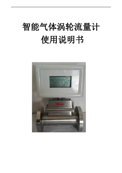
智能气体涡轮流量计使用说明书目录一、概述 (1)二、主要特征 (1)三、技术性能 (1)四、选型与安装 (3)五、安装注意事项 (7)注意!●安装使用前,请仔细阅读本说明书理解各项内容,以便能正确的安装、电路连接、运行操作和保养维护等。
●本说明书应保存在实际最终使用人的手中。
●本说明书保存到流量计报废为止。
●本产品技术规范可能发生变化,恕不另行通知。
一、概述LWQ型气体涡轮流量计是一种精确测量气体流量的速度式流量仪表,具有结构简单轻巧、计量精度高、重复性好、测量范围宽、安装维修方便等优点。
广泛应用于石油、化工、冶金、航空、科研等部门及工业领域中多种气体,如天然气、城市煤气、丙烷、丁烷、空气、氮气等气体的测量。
由于仪表精度高、重复性好,故适用于贸易计量及工业过程检测。
气体涡轮流量计在线测量时,其介质密度随温度和压力变化而变化,为精确测量,必须同时跟踪检测介质的温度和压力,并将不同工况下的体积流量换算成标准状态或约定状态下的体积流量。
由于该型流量计集温度、压力、流量传感器于一体,在线跟踪检测介质温度和压力并进行自动补偿、压缩因子修正运算,因此具有优良的低压和高压计量性能,特别适用于各种单相气体的测量,如天然气等气体的精确计量。
根据用户的不同要求,共公司客提供不同精度等级的涡轮流量计。
二、主要特征a)精度高、重复性好、压力损失小、抗震性能好;b)采用优质轴承,摩擦阻力小,密封性好,手名称;c)集微处理器、流量传感器、高精度温度、压力传感器于一体,直接测量被测气体的流量、温度、压力,并自动进行流量跟踪补偿和压缩因子修正运算;d)仪表具有脉冲信号、模拟信号输出,可通过RS485通讯接口或采用GPRS系统,直接实现计算机数据的集中采集和实时管理;e)功耗低,可用内电池供电,也可外接电源;f)具有实时数据存储功能,可防止更换电池或突然掉电时数据丢失,在停电状态下,内部数据可永久保存;g)可与IC卡预付费系统配套使用,便于贸易结算;h)防爆产品其防爆标志位ExibIIBT4,ExibIIBT6三、技术性能3.1执行标准GB/T18940-2003《封闭管道中气体流量的测量涡轮流量计》3.2精度等级1.0级:Qmax-0.2max±1.0%0.2Qmax-min±2.0%1.5级:Qmax-0.2max±1.5%0.2Qmax-min±3.0%未特殊注明产品,按照1.5级精度出厂,其余精度,订货时,需要特殊说明定制。
1.概述LWQ系列气体涡轮流量计是吸取了国内外流量仪表先进技术经过优化设计,综合了气体力学、流体力学、电磁学等理论而自行研制开发的集温度、压力、流量传感器和智能流量积算仪于一体的新一代高精度、高可靠性的气体精密计量仪表,具有出色的低压和高压计量性能,多种信号输出方式以及对流体扰动的低敏感性,广泛适用于天然气、煤制气、液化气、轻烃气等气体的计量。
该产品经国家防爆产品质检部门按GB3836.2000《爆炸性气体环境用电气设备第1部:通用要求》,GB3836.2-2000《爆炸性气体环境用电气设备第2部分:隔爆型“d”》和GB3836.4-2000《爆炸性气体环境用电气设备第4部分:本质安全型“i”》标准检验合格,防爆标志为ExdⅡBT6(隔爆型)、ExiaⅡCT6(本安型)。
适用于含有ⅡA、ⅡB、ⅡC类T1~T4温度组别爆炸性气体混合物的0(仅本安型)1、2区危险场所。
2.产品特点⏹优质合金涡轮,具有更高的稳流和耐腐蚀作用⏹进口优质专用轴承,使用寿命长⏹计量室与通气室隔绝,保证了仪表的安全性⏹可检测被测气体的温度、压力和流量,能进行流量自动跟踪补偿,并显示标准状态下(P b=101.325KPa,T b=293.15K)的气体体积累积量;可实时查询温度压力数值⏹流量范围宽(Q max/Q min≥20:1),重复性好,精度高(可达1.0级),压力损失小,始动流量低,可达0.6m3/h ⏹智能化仪表系数多点非线性修正⏹内置式压力、温度传感器,安全性能高、结构紧凑、外形美观⏹仪表具有防爆及防护功能,防爆标志为ExdⅡBT6、ExiaⅡCT6,防护等级为IP65⏹系统低功耗工作,一节3.2V10AH锂电池可连续使用3年以上⏹仪表系数、累计流量值掉电十年不丢3. 工作原理当流体流入流量计时,在进气口专用一体化整流器的作用下得到整流并加速,由于涡轮叶片与流体流向成一定角度,此时涡轮产生转动力矩,在克服摩擦力矩和流体阻力矩后,涡轮开始旋转。
青岛奥博仪表设备有限公司目录1、用途: (1)2、工作原理: (1)3、特点: (1)4、主要技术参数: .............................1-25、仪表结构及安装方式: .......................2-36、电气特性...................................3-47、安装尺寸 (4)8、附录-现场显示型仪表操作说明................5-13一、用途:气体涡轮流量计是一种速度式仪表。
它具有精度高、重复性好、结构简单、测量范围宽、体积小、重量轻、压力损失小、维修方便等优点。
可广泛应用于石油、化工、冶金、城市燃气管网等行业。
尤其在城市燃气计量,输配管网计量以及燃气调压站计量中得到了广泛应用。
二、工作原理:3、使用条件:(1)环境温度:-20℃~50℃;(2)相对湿度:5%~95%;(3)被测介质温度:-20℃~80℃;(4)大气压力:86Kpa~106Kpa;(5)防爆等级:ibⅡBT4。
4、流量计特性曲线图:五、仪表结构及安装方式:图a图bLWQ DN≤40mm安装示意图LWQ DN≥ 50MM安装示意图1、仪表安装采用法兰连接、螺纹连接及夹装式;2、安装时气体流动方向应与传感器外壳上指示流向的箭头方向一致,且上游直管段应≥10DN,下游直管段应≥5DN(DN为管道内径);3、安装前检查仪表叶轮的灵活性,用微量气体吹向涡轮,叶轮应灵活转动、计数器工作正常,无噪音和突停、卡滞现象;4、严禁带表焊接法兰,并严格清理过滤器和流量计之间的上游直管段,直管段中不得有残留焊渣及其他杂物;5、按安装图要求安装并检查整个系统密封性,保证无气体泄露现象;6、为了检修时不影响气体的正常输送,应在传感器的安装处安装旁通管道(见图c)。
图c 传感器安装管道示意图六、电气特性:在测量系统中,累计流量的表达方式为:V=N/K;在测量系统中,瞬时流量的表达方式为:Q=(f/K)×3600;由于K值在较宽的测量范围内并非单一值,它是信号频率的函数。
LWGQ型气体涡轮流量传感器使用说明书1、概述本说明书注意叙述了LWGQ气体涡轮流量计的标准技术规格、型号及其安装、操作和维修。
请在使用前阅读本手册。
但在手册中没有叙述用户的不同特点,也未对每一次的技术规格、结构或部件的修改作订正,因为有些修改不会对仪器的功能和操作有影响。
LWGQ气体型涡轮流量传感器(以下简称传感器)是一种精密流量测量仪表,与相应的流量积算仪表配套可用于测量液体的流量和总量。
广泛用于石油、化工、冶金、科研等领域的一般气体、天然气、煤气等气体计量、控制系统。
传感器和输出放大器有多种组合(详见型号规格代码表),该传感器还可与控制室中的二次仪表或控制器相连,实现积算、传输和控制功能。
2、技术性能传感器的公称通径、流量范围、流体温度、公称压力、环境温度、相对湿度、最大压力损失见表1,型号、规格代码表见表2。
注:1、法兰连接尺寸按JB/T 81-1994或JB/T 79-1994。
2、有*者为特殊定货3、结构与工作原理3.1结构传感器的结构如图1所示,它主要由壳体、前导向架、叶轮、后导向架、压紧圈和带放大器的磁电感应转换器等组成;3.2工作原理当被测流体流经传感器时,传感器内的叶轮借助于流体的动能而产生旋转,叶轮即周期性地改变磁电感应系统中的磁电阻,使通过线圈的磁通量周期性地发生变化而产生电脉冲信号,经放大器放大后传送至相应的流量积算仪表,进行流量或总量的测量。
4、外形尺寸及安装4.1外形尺寸1、公称通径DN15~25(公称压力PN6.3Mpa 见图2,表3)2.公称通径DN40~80,在公称压力PN1.6Mpa和PN2.5Mpa时,法兰连接尺寸DN100~200中,带括号者为公称压力PN2.5Mpa的法兰尺寸。
DN250,300公称压力PN1.6Mpa。
3.一般出厂产品配公称压力PN1.6Mpa的法兰。
4.2安装1.安装的场所传感器应在被测气体的温度为-20~+60℃,环境相对湿度不大于95%的条件下工作。
气体涡轮流量计产品说明:1.概述LWQ-D型气体涡轮流量计是吸取了国内外流量仪表先进技术经过优化设计,综合了气体力学、流体力学、电磁学等理论而自行研制开发的集温度、压力、流量传感器和智能流量积算仪于一体的新一代高精度、高可靠性的气体精密计量仪表,具有出色的低压和高压计量性能,多种信号输出方式以及对流体扰动的低敏感性,广泛适用于天然气、煤制气、液化气、轻烃气等气体的计量。
该产品经国家防爆产品质检部门按GB3836.2000《爆炸性气体环境用电气设备第1部:通用要求》,GB3836.2-2000《爆炸性气体环境用电气设备第2部分:隔爆型“d”》和GB3836.4-2000《爆炸性气体环境用电气设备第4部分:本质安全型“i”》标准检验合格,防爆标志为ExdⅡBT6(隔爆型)、ExiaⅡCT6(本安型)。
适用于含有ⅡA、ⅡB、ⅡC类T1~T6温度组别爆炸性气体混合物的0(仅本安型)1、2区危险场所。
该系列流量计采用先进的超低功耗单片微机技术研制的涡轮流量传感器与显示积算一体化的新型智能仪表,通过微处理单元对由温度和压力检测模拟通道、流量传感器通道采集的信号按照气态方程进行温度压力补偿,自动进行压缩因子修正,在液晶显示器将全部数据(瞬时流量、日累积流量、总累积流量、温度、压力、时间、日期、电池电量)直观的显示出来,并可输出工况、标况脉冲信号、4-20mA、RS485、IC卡信号等多种通讯信号。
仪表采用内置锂电池和外供24VDC双供电方式,当用户不需要任何信号输出功能时可不用对仪表24VDC外供电,仪表自动切换到内置锂电池供电,电池电量可连续工作3年以上。
该类涡轮流量计为防爆产品,防爆等级为:ExdIIBT6我公司生产的LWQ系列气体涡轮已由Ⅱ代产品升级为Ⅲ代产片。
与Ⅱ代产品相比,Ⅲ代产品具有更出色的性能,稳定性更强,集成度更高,更加美观。
2.产品特点⏹优质合金涡轮,具有更高的稳流和耐腐蚀作用⏹进口优质专用轴承,使用寿命长⏹计量室与通气室隔绝,保证了仪表的安全性⏹可检测被测气体的温度、压力和流量,能进行流量自动跟踪补偿,并显示标准状态下(P b=101.325KPa,T b=293.15K)的气体体积累积量;可实时查询温度压力数值⏹流量范围宽(Q max/Q min≥20:1),重复性好,精度高(可达1.0级),压力损失小,始动流量低,可达0.6 m3/h⏹智能化仪表系数多点非线性修正⏹内置式压力、温度传感器,安全性能高、结构紧凑、外形美观⏹仪表具有防爆及防护功能,防爆标志为ExdⅡBT6、ExiaⅡCT6,防护等级为IP65⏹系统低功耗工作,一节3.2V10AH锂电池可连续使用3年以上⏹仪表系数、累计流量值掉电十年不丢3.技术参数:3.1 基本参数:3.1.1表13.1.2精度等级:1.0级、1.5级3.1.3 使用条件:· 环境温度:-30℃~+ 60℃ ; · 大气压力:86KPa ~106KPa ; · 介质温度:-30℃~+ 80℃ ; · 相对湿度:5%~95%3.2 测量范围及工作压力:表2(注:表2所示测量范围均为工作状态下流量范围)表23.3 仪表选型1.选型说明用户在选型时,应根据管道公称压力、介质最高压力、介质温度、介质组分情况、流量范围及信号输出要求合理选择流量计的型号规格。
气体涡轮流量计说明1.概述LWQ系列气体涡轮流量计是我公司新研发的新型气体涡轮流量计,借鉴航空技术的先进理念综合了流体力学、电磁学等理论而自行研制开发的集温度、压力、流量传感器和智能流量积算仪于一体的新一代高精度、高可靠性的气体精密计量仪表,具有出色的低压和高压计量性能,多种信号输出方式以及对流体扰动的低敏感性,广泛适用于天然气、煤制气、液化气、轻烃气等气体的计量。
结合现代化的加工设备,应用完善有效的工艺手段。
生产的流量计结构合理,耐用性好,重复性好,安装方便简洁。
我公司为广大用户提供高可靠性的产品,研发阶段在轴承生产商的配合下,进行了为期八个月的每天24小时连续的耐久性实验,摸透了轴承和结构的可靠性,表芯采用一体化设计。
为您提供一流的产品,一流的可靠性保证。
减少您的售后负担。
该产品经国家防爆产品质检部门按GB3836.2000《爆炸性气体环境用电气设备第1部:通用要求》,GB3836.2-2000《爆炸性气体环境用电气设备第2部分:隔爆型“d”》和GB3836.4-2000《爆炸性气体环境用电气设备第4部分:本质安全型“i”》标准检验合格,防爆标志为ExdⅡBT6(隔爆型)、ExiaⅡCT6(本安型)。
适用于含有ⅡA、ⅡB、ⅡC类T1~T4温度组别爆炸性气体混合物的0(仅本安型)1、2区危险场所。
2.产品特点⏹优质铝合金涡轮,具有更高的稳流和耐腐蚀作用⏹专用轴承,使用寿命长⏹计量室与通气室隔绝,保证了仪表的安全性⏹可检测被测气体的温度、压力和流量,能进行流量自动跟踪补偿,并显示标准状态下(P b=101.325KPa,T b=293.15K)的气体体积累积量;可实时查询温度压力数值⏹流量范围宽(Q max/Q min≥20:1),重复性好,精度高(可达1.0级),压力损失小,始动流量低,可达0.6m3/h⏹智能化仪表系数多点非线性修正⏹内置式压力、温度传感器,安全性能高、结构紧凑、外形美观⏹仪表具有防爆及防护功能,防爆标志为ExdⅡBT6、ExiaⅡCT6,防护等级为IP65⏹系统低功耗工作,一节3.2V10AH锂电池可连续使用3年以上⏹仪表系数、累计流量值掉电十年不丢3. 工作原理当流体流入流量计时,在进气口专用一体化整流器的作用下得到整流并加速,由于涡轮叶片与流体流向成一定角度,此时涡轮产生转动力矩,在克服摩擦力矩和流体阻力矩后,涡轮开始旋转。
CX CX--TFM TFM--LWQ LWQ 气 体 涡 轮 流 量 计使用使用说明书说明书目录1、概述1.1搬运时应注意的事项1.2存放应注意的事项1.3选择安装地点应注意的事项1.4限制使用无线电收发机应注意的事项1.5防爆型仪表安装注意事项2、技术性能2.1气体涡轮流量传感器的技术性能2.2LRT-I现场显示表(锂电池供电)的技术性能2.3LRT-Ⅱ现场显示表(外供电)的技术性能2.4LRT-Ⅲ现场显示表(外供电)的技术性能3、结构与工作原理3.1气体涡轮流量传感器的基本结构3.2工作原理4、外形尺寸及安装4.1外形尺寸4.2安装5、接线5.1放大器及现场显示表的接线5.2应用举例6、LRT-I和LRT-Ⅱ现场显示表的安装和操作6.1LRT-I、LRT-Ⅱ现场显示表的安装6.2LRT-I、LRT-Ⅱ现场显示表的结构和功能6.3参数设定步骤6.4锂电池更换(仅LRT-I)7、LRT-Ⅲ现场显示表的安装和操作7.1LRT-Ⅲ现场显示表的安装7.2LRT-Ⅲ现场显示表的结构和功能7.3显示段中的内容7.4参数设定步骤7.5报警数字显示模式8、流量传感器的维护9、流量传感器故障及故障排除方法装箱单1、概述本说明书叙述了LWGQ气体涡轮流量计的标准技术规格、型号及其安装、操作和维护。
请在使用前阅读本手册。
但在手册中没有叙述用户的不同特点,也未对每一次的技术规格、结构或部件的修改作订正,因为有些修改不会对仪器的功能和操作有影响。
LWGQ型气体涡轮流量计是一种精密流量测量仪表,与相应的流量积算仪表、现场显示表等配套可用于测量液体的流量和总量。
它被广泛用于石油、化工、冶金、科研等领域的计量、控制系统。
尤其适用于天然气、干煤气、压缩空气等的测量。
流量计有多种输出和显示方式(详见型号规格代码表)。
1.1搬运时应注意的事项为防止受到损坏,流量计在搬运到用户使用地点之前请使用原包装。
1.2存放应注意的事项仪器到达之后应及时安装。