No mass drop for mean curvature flow of mean convex hypersurfaces
- 格式:pdf
- 大小:260.69 KB
- 文档页数:23

汽车行业术语(下)nondis persi ve ultrav iolet氢火焰离子化检测器flameioniza tionditect or总碳氢化合物分析仪totalhydroc arbon analyz er气相色谱仪gas chroma togra ph化学发光检测器chemil umine scent detect or臭氧发生器ozonat or底盘测功机chassi s dynamo meter惯性模拟系统inerti a simula tionsystem功率吸收装置device for powerabsorp tion转鼓roller空气阻力aerody namic resist ance滚动阻力rollin g resist ance当量惯量equiva lentinerti a滤纸式测试仪filter-type measur ing appara tus 转速表tachom eter成套分析设备analyt icaltrain组合气室stacke d cell参比室refere nce cell滤光室filter cell干扰滤光器interf erent ial filter加热式氢火焰离子化检测器heated flameioniza tiondetect or 氮氧化合物转化器Nox conver ter(No2-NO)反应室reacti ve cell (chambe r)催化燃烧分析仪cataly tic combus tionanalyz er碳氢化合物响应度hydroc arbon respon se碳数当量carbon equiva lent百万分率碳partsper millio n carbon (ppmC) 氧干扰oxygen interf erenc e氧校正oxygen correc tion湿度较正系数humidi ty correc tion(kh)factor拖尾tailin g五氧化二碘法iodine penta-oxidemethod平衡气balanc e gas零点气zero gradegas (air zero gas)校正气calibr ating gas量距气span gas拉格朗日拟合lagran gianfit二氧化碳干扰校正correc ted for CO2 extrac tion袋式分析bag analys is柴油机排烟测定仪器diesel smokemeasur ing instru ment排气烟度opacit y of exhaus t gas烟度计opacim eter全流式烟度计full flow opacim eter取样烟度计sampli ng opacim eter光线有效通过长度effect ive path length of lightray 吸光系数lightabsorp tioncoeffi cient峰值储存器peak hold device烟室smokechambe r引进气体incomi ng gas排出气体outgoi ng gas色温colortemper ature人眼的感光曲线photop tic curveof humaneye 光谱反应曲线spectr al respon se curve光源lightsource光束lightbeam直接光线direct lightray反射光线reflec ted lightrays散射光diffus ed light光通量lightlux中性滤波仪neutra l optica l filter烟度计物理反应时间physic al respon se time of opacim eter电气响应时间electr icalrespon se time倍频程octave热时常数therma l time-consta nt烟柱smokecolumn标定用遮光片calibr ating screen示踪气体tracer gas扫气scaven ge air冷却装置coolin g device膨涨箱expans ion tank暗度刻度obscur ation scale光学试验台optica l bench热电偶thermo coupl e气密性gas tightn ess阻尼室dampli ng chambe r烟度计smokem eter光学式烟度计optica l smokem eter不透光式烟度计smokeopacim eter比尔-朗伯定律beer-lamber t law不透光度opacit y (lgihtobscur ation )(N)透光度transm ittan ce(t)光吸收系数coeffi cient of lightabsorp tion(k) 光通道有效长度effect ive optica l path length(L) 滤纸式烟度计filter type smokem eter有效长度effect ive length抽气量sweptvolume滤纸有效面积effect ive filter area死区容积dead volume烟度单位smokeunit(index)滤纸式烟度单位filter smokenumber (FSN)内装式烟度计built-in (in-line)smokem eter外装式烟度计mounte d(end-of line) smokem eter全流式烟度计full-flow smokem eter部分流式烟度计part-flow smokem eter取样探头probe排气收集系统exhaus t gas collec tionequipm ent稀释空气样气收集袋sample collec tionbag for diluti on air稀释空气取样探头sample probefor diluti on air稀释排气混合气收集袋sample collec tionbag for dilute exhaus t mixtur e 取样方法和设备sampli ng method and device全流取样法full flow sampli ng部分流取样法partia l flow sampli ng定容取样法consta nt volume sampli ng (CVS) 全量袋式取样法totalbag sampli ng比例取样法propor tiona l smapli ng直接取样法direct sampli ng method动态或连续取样法dynami c or contin uoussampli ng 容积式泵positi ve displa cemen t pump临界流量文杜里管critic al flow ventur i稀释系数diluti on factor稀释用空气diluti on air稀释排气dilute d exhaus t稀释风道diluti on ratio取样探管diluti on tunnel取样袋sampli ng bag逆向清洗back flush试验方法和限值testin g method and limits 试验循环test cycle行驶循环drivin g cycle工况mode行驶监视仪driver aid中间转速interm ediat e speed加权系数weight ing coeffi cient美国烟排放物试验循环US EPA smokeemissi on test cycle全负荷法full load method自由加速法free accele raton method加载减速法lug down method稳定单速法single steady speedmethod道路试验法road test method滑行法coastd own密闭室测定蒸发排放物法(SHED)sealed housin g ofr evapor ative emissi on determ inati on (SHED) 运转损失runnin g losses热浸损失hot soak losses昼间换气损失diurna l breath ing losses美国LA-4C法USEQPA-4CH test proced ure美国LA-4CH法US EPA 4CH test proced ure美国九工况法US EPA 9 -mode test cycle美国十三工况法US EPA 13-mde test cycle美国重型柴油机瞬态法US EPA heavyduty diesel engine transi ent test cycle日本四工况法Japane se 4-mode test cycle日本十工况法Japane se 10/11-mode test cycle日本六工况法Japane se 6-mode test cycle欧洲ECE十五工况法ECE 15-mode test cycle排放限值emissi on limits怠速排放限值idle speedemissi on limits浓度排放限值emissi on concen trati on limits质量排放限值mass rate of emissi on limits净化purify ing净化率purify ing rate在用车in-use vehicl e无铅汽油unlead ed gasoli ne务化系数(DF)deteri orati on factor(DF) 车辆类型vehicl e type道路车辆road vehicl e商用车辆commer cialvehicl e机动车辆motorvehicl e电动车辆electr ic vehicl e摩托车motorc ycle轻便摩托车moped轿车passen ger car微型轿车minica r普通级轿车subcom pactcar中级轿车compac t car中高级轿车interm ediat e car高级轿车limous ine (pullma n saloon)活顶轿车conver tible saloon旅行轿车statio n wagon短头轿车forwar d contro l passen ger car 小型轿车coupe敞蓬小轿车drop head coupe跑车sports car赛车racer(racing car)单座小客车one-seater七座小客车seven-seater越野车off-road vehicl e轻型越野车light-off-road vehicl e中型越野车medium off-road vehicl e重型越野车heavyoff -road vehicl e超重型越野车extraheavyoff- road vehicl e 吉普车jeep硬顶吉普车hard top jeep客车bus微型客车minibu s轻型客车lightbus中型客车medium bus大型客车largebus客货两用小客车estate car (estate) 多用途客车multip urpos e vehicl e 厢式小客车closed car出租小客车taxica r城市客车urbanbus大客车coach城间大客车interc ity bus长途大客车long distan ce coach旅游客车sights eeing bus(tourin g bus) 铰接客车articu lated bus无轨客车trolle y bus双层客车double-deck bus团体客车privat e coach货车truck(lorry)微型货车mini-truck轻型货车lighttruck中型货车medium truck重型货车heavytruck公路货车highwa y vehicl e小型货车pick-up平板货车platfo rm truck(flat bed truck)通用货车genera l -purpos e vehicl e短轴距货车short-wheelbase truck长轴距货车long-wheelb ase truck集装箱运输货车contai ner carrie r客货两用车cargo-bus厢式货车van牵引汽车towing vehicl e全挂牵引汽车towing vehicl e牵杆式牵引车full-traile r towing vehicl e 半挂牵引车semi-traile r towing vehicl e 道路列车road train客用道路列车passen ger road train铰接式道路列车articu lated road train双挂式道路列车double road train混合式道路列车compos ite road train天然气车辆natura l gas vehicl e(NGV)压缩天然气车辆compre ssednatura l gas vehicl e 液化天然气车辆liquid petrol eum gas vehicl e液化石油气车辆liquid petrol eum gas vehicl e双燃料车辆duel fuel vehicl e单燃料车辆single fuel vehicl e专用车specia l vehicl e垃圾车dust car (refuse collec tor)冷藏车refrig erate d van洒水车street sprink ler (street flushe r) 囚车prison van殡仪车hearse售货车mobile store(mobile shop)图书馆车mobile librar y宣传车mobile louder speak er商业广告车spieltruck展览汽车demons trati on car博览会专用车fairgr oundvehicl e流动艺术展览车artmob ile邮政车mobile post office运油车fuel tanker加油车refuel ler飞机牵引车aircra ft tracto r救护车ambula nce (medica l vehicl e) 病院汽车clinic car医疗急救车rescue ambula nceX射线诊断车mobile-x-ray clinic防疫监测车mobile epidem ic contro l vehicl e 计划生育车mobile family -planni ng clinic伤残者运送车handic apped person carrie r炊事车kitche n vehicl e餐车mobile cantee n沐浴车mobile shower bath保温车insula ted van电视转播车TV relayi ng vehicl e电视录像车videorecord ing vehicl e摄影车mobile photog raphi c studio电影放映车film projec tionvehicl e邮件运输车mail carrie r农用车farm vehicl e种子检测车plantseedsinspec tionvan植物保护车plantpest contro l vehicl e计量检测车metrol ogy inspec tionvehicl e环境检测车mobile enviro nment monito r畜禽防疫车mobile animal eqidem ic contro l 交通监理车traffi c contro l car刑事勘察车mobile crimeinvest igati on vehicl e 气卸散装水泥车bulk-cement pneuma tic delive ry tanker气卸散装煤粉车bulk-coal powder pneuma tic delive ry tanker气卸散装电石粉车bulk-calciu m carbid e pneuma tic delive ry tanker 气卸散装化学粉粒车bulk-chemic als pneuma tic delive ry tanker食用植物油运油汽车edible oil tanker食用植物油加油车edible oil pump delive ry tanker活鱼运输车life fish carrie r气卸散装面粉车bulk-flourpneuma tic delive ry tanker吸尘车vacuum sweepe r高压清洗车high-pressu re sewerflushi ng vehicl e吸污车suctio n -type sewerscaven ger 真空吸粪车suctio n -type tumbre l tanker 自装卸垃圾车refuse collec tingtruck旋转板自装卸垃圾车compre ssion refuse collec tor 航空食品装运车aircra ft catere r's delive ry truck散装粮食运输车bulk-graincarrie r散装饲料运输车bulk-fodder transp ort truck牲畜运输车livest ock carrie r家禽运输车poultr y carrie r养蜂车mobile bee-keeper原木运输车loggin g transp orter管材运输车pole transp orter车辆运输车car transp orter锅炉车mobile boiler除雪车snow sweepe r机场客梯车mobile aircra ft landin g stairs 消防车fire-fighti ng vehicl e水罐消防车fire-exting uishi ng watertanker 泡沫消防车fire-exting uishi ng foam tanker 救火泵车fire pumper消防水罐车fire tanker泡沫灭火车foam vehicl e消防指挥车fire servic e comman dingcar 云梯消防车fire-fighti ng trunta ble ladder 厢式汽车van厢式零担运输车breakbulk cargocarrie r罐式汽车tanker酸罐车acid tanker液化气罐车liquif ied gas tanker奶罐车milk tanker食品液罐车bevera ge tanker背罐车demoun table tanker carrie r装卸机械loadin g (unload)machin e叉式装货机fork-type loadin g (unlaod)machin e 刮板式装货机scrape r type loadin g machin e单斗式装货机single bucket loadin g machin e带升降塔架车辆towercrane塔式超重机towercrane汽车吊车truckcrane移动式起重机mobile crane固定式起重机statio narycrane起重举升汽车crane/lift truck特种结构汽车specia l constr uctio n vehicl e随车起重运输车truckwith loadin g crane后栏板起重运输车tail-lift truck高空作业车hydrau lic aerial cage(公路事故或故障车辆的)急修车breakd own truck修理车mobile worksh op救险车recove ry vehicl e技术服务车servic e car现场用小车spot dolly工具车tool car故障检修车troubl e car勘测工程车record ing bus筑路工程用车road machin e压路机road roller推土机ball dozer平路机motorgrader铲运机wheele d loadin g shovel 轮式装载车wheele d loader轮式挖掘机wheele d excava tor混凝土搅拌车concre te mixertruck焊接工程车mobile weldin g worksh op沥青洒布车asphal t distri butio n truck沥青路面养护车asphal t paveme nt mainte nance truck沥青运输车heated bitume nt tanker建筑大板运输车prfabbuildi ng paneltransp orter电信工程车teleco mmuni catin fieldservic e truck工程机械运输车constr uctio n machin ery transp orter 仓栅式汽车storag e/staketruck钻孔立柱车pole drilland erecti on truck油田试井车oil-well testin g vehicl e井架运输车derric k transp orter修井车well mainte nance vehicl e地锚车mobile ground anchor vehicl e灌注车oil well cracki ng acid pumpin g truck照明车floodlighti ng vehicl e后翻倾式自卸汽车rear dump truck两侧翻倾式自卸汽车side dump truck三面翻倾式自卸汽车three-way dump truck重型自卸汽车heavyduty dump truck矿用自卸汽车mining dump truck专用自卸汽车specia l dump truck摆臂式自装卸汽车swept-body dump truck车厢可卸式汽车roll-off skip loader全挂车full traile r半挂车semi-traile r特种挂车specia l traile r栏板货厢式挂车cargotraile r平板式挂车flat platfo rm traile r低架式挂车low-loader traile r厢式挂车traile r van自卸式挂车dumper traile r旅居挂车carava n动物集装箱live-stockcontai ner 干货集装箱dry cargocontai ner 保温集装箱isothe rmalcontai ner 框架集装箱flat rack contai ner 散货集装箱bulk contai ner罐式集装箱tank contai ner冷藏集装箱refrig erate d contai ner质量mass净底盘干质量bare chassi s dry mass净底盘整备质量bare chassi s kerb mass底盘与驾驶室干质量chassi s and cab dry mass底盘与驾驶室整备质量chassi s and cab kerb mass整车交运质量comple te vehicl e shippi ng mass 整车整备质量comple te vehicl e kerb mass最大设计总质量maximu m design totalmass最大允许总质量maximu m autohr ozedtotalmass最大设计装载质量maximu m design pay mass最大允许装载质量maximu m autoho rized pay mass厂定最大总质量manufa cture r's maxumu m totalmass 载重量payloa d车辆自重kerb weight总重量grossweight轴荷axle load最大设计轴荷maximu m design axle load最小设计轴荷minimu m author izedaxle load最大允许轴荷maximu m design axle load轮胎最大设计拖挂质量maximu m design tyre load最大设计拖挂质量maximu m author izedtyre load最大允许拖挂质量maximu m author izedtowedmass汽车列车最大设计质量maximu m design mass of vehicl e combin ation汽车列车最大允许质量maximu m author izedmass of vehicl e combin ation铰接车最大设计质量maximu m disgnmass of articu lated vehicl e铰接车最大允许质量maximu m author izedamss of articu lated vehicl e半挂牵引车承受的最大静载荷maximu m design static laod borneby semi-traile r towing vehicl e 作用在挂接装置上的最大设计静载荷maximu m design static laod on coupli ng device作用在挂接装置上的最大允许静载荷maximu m author izedstatic load on coupli ng device比功率power/mass ratio比扭矩torque/maximu m totalmass ratio重量利用系数factor of weight utiliz aton汽车型谱chartof automo tivemodel后驱动汽车rear driveautomo bile前驱动汽车frontdriveautomo bile发动机后置式客车bus with rear engine四轮驱动车辆all wheeldriveautomo bile发动机前置式客车bus with frontengine发动机底置式客车bus with underf loorengine计算机辅助设计comput er aideddeisgn(CAD)有限寿命设计design for finite life累积疲劳损伤原理theory of cumula tivedamage in fatiqu e优化设计optimu m deisgn汽车尺寸控制图sketch on layout ofr dimens hion's contro l of assemb ly 汽车总装配图automo bileassemb ly drawin g汽车总布置草图sketch for automo bilelayout汽车设计的技术经济分析techni cal -econom ic analys is in automo biledesign设计任务书design assign ment系列化、通用化、标准化seriat ion ,univer saliz ation and standa rdiza tion总布置设计calcul ation for layout 运动校核correc tionof motion 侧视轮廓side outlin e前视轮廓end outlin e顶视轮廓plan outlin e车长vehicl e length车宽vehicl e width车高vehicl e height轴距wheelbase轮距track前轮距trackfront后轮距trackrear双胎间距spacebetwee n twin wheels前悬frontoverha ng后悬rear overha ng离地间隙ground cleara nce纵向通过角ramp angle接近角approa ch angle离出角depart ure angle车架高度height of chassi s aboveground驾驶室后车架最大可用长度maximu m usable length of chassi s behind cab 车身长度body work length车厢内部最大尺寸maximu m intern al dimens ion of body货厢内长loadin g spacelength货厢有效长度loadin g length货厢内宽loadin g spacewidth货厢有效内宽loadin g width货厢内高loadin g spaceheight货厢有效内高loadin g height货台高度loadin g surfac e height车架自由长度framefree length栏板内高inside boardhegiht货厢容积loadin g surfac e门高door height门宽door width车架有效长度chassi s frameuseful length货厢全长body length牵引杆长drawba r length牵引装置的位置positi on of towing attach ment牵引装置的悬伸overha ng of towing atachm ent牵引装置的高度heigth of towing attach ment牵引装置牵距distan ce of towing attach ment牵引座前置距fifthwheellead长度计算用牵引座前置距fifthwheellead for calcul ation of length质量分配用牵引座前置距fith wheellead for calcul ation of mass distri butio n牵引座结合面高度height of coupli ng face牵引装置至车辆前端的距离distan ce betwee n towing device and frontend of towing vehicl e 牵引叉销至车辆前端的距离distan ce betwee n jaw and frontend of towing vehicl e半挂车间隙半径rear tracto r cleara nce radius of semi-traile r半挂车前回转半径frontfittin g radius of semi traile r车轮垂直行程vertic al cleara nce of wheel车轮提升高度lift of wheel转弯半径turnin g circle静止半径static radius碰撞collis ion (crash,impact)正碰撞fronta l collis ion (fronta l impact) 侧碰撞side collis ion (side impact)后碰撞rear collis ion (rear impact)擦碰撞sidewi pe collis ion碰撞方向collis ion direct ion碰撞角度collis ion angle倾斜的obliqu e(tilt)成角度的angled纵向的longit udina l垂直的perpen dicul ar对中center ed偏置offset重叠overla p碰撞轴线排列collis ion axis alignm ent 纯正撞pure fronta l impact。

第57卷 第1期2021年1月石 油 化 工 自 动 化AUTOMATIONINPETRO CHEMICALINDUSTRYVol.57,No.1Jan,2021稿件收到日期:20201013,修改稿收到日期:20201117。
作者简介:徐伟清(1963—),男,1985年毕业于浙江大学生产过程自动化专业,现就职于中石化南京工程有限公司,主要从事石油化工自控工程专业管理以及总承包项目的管理工作。
高纯气体流量测量中的仪表选型徐伟清(中石化南京工程有限公司,江苏南京211100)摘要:高纯气体具有组分稳定,无尘、无水滴、无油污的特点,为流量测量和流量计的稳定运行创造了良好的条件。
通过对比差压式流量计和热式质量流量计的工作原理及在高纯气体实际测量中的应用,介绍了选用两种流量计的条件,分析了差压式流量计和热式质量流量计在实际测量中存在的误差原因,并给出了相应解决方案。
关键词:高纯气体;流量测量;双量程差压流量计;过程控制;贸易交接计量;热式质量流量计中图分类号:TH814 文献标志码:B 文章编号:10077324(2021)01006904犐狀狊狋狉狌犿犲狀狋犜狔狆犲犛犲犾犲犮狋犻狅狀犳狅狉犎犻犵犺犘狌狉犻狋狔犌犪狊犉犾狅狑犕犲犪狊狌狉犲犿犲狀狋XuWeiqing(SinopecNanjingEngineeringCo.Ltd.,Nanjing,211100,China)犃犫狊狋狉犪犮狋狊:Thehighpuritygasisofthecharacteristicsofstablecomponent,nodust,nowater dropandnooilpollution.Itcreatesgoodconditionforflowmeasurementandstablerunningforflowmeter.Throughcomparisonoftheworkingprinciplefordifferentialpressureflowmeterandthermalmassflowmeter,andtheapplicationofpracticalmeasurementforhighpuritygas,theconditionsfortheselectionofthesetwokindsofflowmeterareintroduced,andtheerrorcauseexistingintheactualapplicationforthedifferentialpressureflowmeterandthermalmassflowmeterisinvestigated,relevantsolutionisproposed.犓犲狔狑狅狉犱狊:highpuritygas;flowmeasurement;dualrangedifferentialpressureflowmeter;processcontrol;custodytransfermeasurement;thermalmassflowmeter 高纯气体在各行各业和工业生产都有广泛的用途,它通常由空气分离工艺制取,气态高纯气体经管道或钢瓶集装格输送给用户,液态产品用槽车运输给用户。

Mass and Volumetric Gas Flow MetersFor Clean GasesU U p to 18 Hour Battery Charge on Portable“-B” Models U R anges of 0 to 0.5 SCCM Up to 0 to 3000 SLM U R eports Mass Flow, Volumetric Flow,Temperature, and Pressure U <10 ms Response Time—Field Adjustable U 130+ Gas Calibrations IncludingPure and Mixed Gases U P ressure, Temperature and Volumetric orMass Flow Simultaneously Displayed U N IST 5-Point Certificate Included U N o Straight Runs of Pipe Required U No Warm-Up TimeU Turndown Ratio of 200:1 (0.5% Maximum Flow)U RS232 StandardU Custom Live Gas Blend Programming U Store Up to 20 User Defined Gas BlendsThe FMA-1600A Series mass and volumetricflow meters use the principle of differential pressure within a laminar flow field to determine the mass flow rate. A laminar flow element (LFE) inside the meter forces the gas into laminar (streamlined) flow. Inside this region, the Poiseuille equation dictates that the volumetric flow rate be linearly related to thepressure drop. A differential pressure sensor is used to measure the pressure drop along a fixed distance of the LFE. This, along with the viscosity of the gas, is used to accurately determine the volumetric flow rate. Separate absolute temperature and pressure sensors are incorporated and correct the volumetric flow rate to a set of standard conditions. This standardized flow rate is commonly called the mass flow rate and is reported in units such as standard cubic feet per minute (SCFM) or standard liters per minute (SLM).Standard units include a 0 to 5V output (4 to 20 mA optional) and RS232 communications. The gas select feature can be adjusted from the front keypad or via RS232 communications. Volumetric flow, mass flow, absolute pressure, and temperature can all be viewed or recorded through the RS232 connection. It is also possible to multi-drop up to 26 units on the same serial connection to a distance of 38 m (125'). These flow meters are available in a portable version (“-B” option), the battery charge will last up to 18 hours.FMA-1600A SeriesSpecificationsAccuracy: ±(0.8% of rdg + 0.2% FS)Repeatability: ±0.2%Turndown Ratio: 200:1Response Time: 10 ms typical default response time for 63.2% of a step change. A variable register allows response time to be field adjustable to a certain extent via RS232 communications. The primary trade-off for response time is signal noiseOutput: 0 to 5 Vdc standardOperating Temperature: -10 to 50°C (14 to 122°F)Zero Shift: 0.02% FS/°C/atm Span Shift: 0.02% FS/°C/atmHumidity Range: 0 to 100% non-condensing Pressure (Maximum): 145 psig Measurable Flow Rate: 125% FSSupply Voltage: 7 to 30 Vdc (15 to 30 Vdc for 4 to 20 mA output)Supply Current: 35 mA typical current draw; 100 mA available supply recommended Cable Connection: 8-pin mini DINWetted Parts: 302 and 303 SS, FKM, heat cured silicone RTV, glass reinforced PPS, heat cured epoxy, aluminum, gold, brass, 430 FR stainless (416 stainless steel on large sizes), silicon, glassFMA-1603A includes 110 Vac power supply and a 1.8 m (6') cable 8-pin mini DIN connector,Shown smaller than actual size.Exploded View of InternalLaminar Flow Elements Absolute PressureSensorDifferential PressureSensor TemperatureSensorProgram Custom Mixed Calibrationsfor Bioreactors, Chromatography,Welding, Lasers, Stack/Flue, Fuel Gases and MoreComes complete with 24 Vdc universal power supply, 1.8 m (6') cable, 8-pin male Mini-DIN connector, operator’s manual, and NIST certificate. Units are calibrated to air @ 5 psig for 0 to 1 LPM, 15 psig for 2 to 10 LPM, 30 psig for 20 to 100 LPM, and 50 psig for 200 LPM and greater. Calibrations done at ambient 25ºC (77ºF) temperature only.To replace the standard RS232 communications with RS485, add suffix “-RS485” to the model number; for additional cost.Standard input is 0 to 5V, for optional 4 to 20 mA input add suffix “-IN” to the model number; no additional cost.Standard output is scaled to the mass flow rate. For volumetric flow rate as standard output add suffix “-VOL” to the model number; no additional cost. Standard output is 0 to 5V, for optional 4 to 20 mA output, add suffix, “-I” to model number; for additional cost.For two 4 to 20 mA output, add suffix “-I2” to model number; for additional cost.For two 0 to 5V output, add suffix “V2” to model number; for additional cost.**Optional secondary output are scaled the same as the primary output scale. For an alternate output scale add suffix “-T” to the model number for temperature or “-P” for pressure; no additional cost.For a portable version of the meter add suffix “-B” to the model number; for additional cost. Portable versions have an integral battery on the meter and come with one 9V battery installed. Option not available on “-I” or “I2” models where 4 to 20 mA is the chosen output.For units scaled in SCFH, add suffix “-SCFH” to model number; no additional cost. Please specify the desired range in SCFH.For totalizer option, add suffix “-TOT” to the model number; for additional cost. Please specify resolution.This is a 6-digit counter. Examples: For totalizing in liters with 1/100 liter resolution, the max count would be 9999.99. For totalizing in liters with 1 liter resolution, the max count would be 999999.Ordering Examples: FMA-1601A, 0.5 SCCM mass flow meter.FVL-1619A-VOL, 500 SCCM volumetric flow meter.。

FMA-900 SERIESAir Velocity TransducersStandardRemote Probee-mail:**************For latest product manuals:User’sGuideShop online atIt is the policy of OMEGA Engineering, Inc. to comply with all worldwide safety and EMC/EMI regulations that apply. OMEGA is constantly pursuing certification of its products to the European New Approach Directives. OMEGA will add the CE mark to every appropriate device upon certification.The information contained in this document is believed to be correct, but OMEGA accepts no liability for any errors it contains, and reserves the right to alter specifications without notice.WARNING: These products are not designed for use in, and should not be used for, human applications.General DescriptionThe OMEGA ®FMA-900 air velocity mass flow transducer is ideal for economical monitoring of clean air flows in ducts and pipes, while producing very little permanent pressure drop in the flowstream The FMA-900 employs two rugged glass-coated RTD elements, protected by a 1⁄4" diameter 304SS tube with a“window” cut out. One RTD is the velocity sensor, while the other RTD provides ambient air temperature compensation. The velocity sensor is heated to maintain a constant (approximately 30°C) temperature differential above the ambient air temperature, as measured by the second RTD element. The cooling effect of the air flow experienced by the velocity sensor is measured and converted to an electrical output signal proportional to air velocity. The FMA-900 is provided with a 13" long probe as standard. The 304SS tubing is provided with inch marks for ease of insertion depth.UnpackingThe following items are supplied with the FMA-900:•FMA-900 Series Air Velocity Transducer •Mating connector•Removable plastic protective cover (supplied on the sensor tip)•Operator’s manual1-1Important Considerations Before Installationintrinsically safe. Do not use for flammable or hazardous gases, or inhazardous areas.The FMA-900 air velocity transducer is intended for use with clean air or !nitrogen ONLY. Do not use with other gases, as other gases will produce anuncalibrated, non-linear output signal. In addition, air carrying dust or oil (suchas found in blower/compressor systems that utilize oil) can lead to coating of thesensor and thus, inaccurate readings. Refer to the Maintenance section for moreinformation on cleaning the sensor.The FMA-900 is a bi-directional device; flow in the forward or reverse directionprovides the same output.Installing the FlowmeterThe FMA-900 air velocity transducer can be mounted vertically or horizontallywithout shift in calibration.1.Remove the plastic protective cap from the sensor tip.2.Run a length of straight pipe before and after the flowmeter. The amount ofupstream straight pipe run required depends upon the type of obstruction whichis immediately upstream of the flow sensor. See Table 2-1 for specificrequirements. Downstream of the flow sensor, in all situations, run 5 diametersof straight pipe, regardless of the downstream obstruction.3.Align the FMA-900 with the air flow. Make sure the width of the electronics box(2 inches) is parallel with the flow stream.The score line on the tubing is another way of aligning the air flow sensor withthe flow stream. The score line starts from the center of the transducer windowand as a result it can be aligned properly.One means of installing the probe into a flow stream is to utilize a compressionfitting, such as OMEGA’s SSLK-14-14 stainless steel compression fitting withTeflon ferrules, which permits adjustment of the insertion depth of the probe.On Remote Probe Models (-R), connect the remote probe cable to the ElectronicHousing.1-2Table 2-1 Piping Requirements1-3Wiring the Flowmeter1.Connect pins as follows:PLUG PIN NO.DESCRIPTION1 0-5 Vdc or 4-20 mA Output (−)2 0-5 Vdc or 4-20 mA Output (+)3Power Supply (+)4No Connection5No Connection6Power Supply (−)2.Blow clean air through the FMA-900.3.Install the sensor into the pipe or duct.Measuring Air FlowThe FMA-900 measures standard velocity, which is the mass velocity of the airreferenced to 25°C and 760 mm Hg. No temperature or pressure corrections arerequired. Where SCFM (standard cubic feet per minute) measurements aredesired:1.Locate the point of average velocity in the pipe or duct.2.In round pipes, under turbulent flow conditions (where the Reynolds number isgreater than 5,000), mount the velocity sensor approximately 1⁄8of a pipediameter in from the the pipe wall. For example, in an 8" diameter pipe, mountthe probe 1" in from the pipe wall.3.For pipes or ducts where the flow is not turbulent, or the flow profile is notsymmetrical (due to inadequate straight pipe runs, etc.), perform a traverse ofthe duct, in accordance with standard duct traversal methods as recommendedby ASHRAE or the National Air Balance Council.4.To obtain SCFM, once the probe is mounted in the location of average velocity,multiply the average velocity readings (in SFPM, standard feet per minute) bythe cross-sectional area of the pipe or duct, in square feet. For standard pipe,these values can be found in the technical section of the OMEGA CompleteFlow and Level Measurement Handbook and Encyclopedia®. MaintenanceExcept for intermittent removal of the sensor from the line for cleaning, there isno routine maintenance for the FMA-900. If the probe becomes coated with dust,blow the dust away with clean air. If the probe is coated with sticky material,clean it with a solvent which is compatible with epoxy, glass, and 304SS, andwhich will not leave a residue on the sensor. You may clean the sensor withwater or alcohol (Ethanol) and an artist’s brush.CalibrationEach FMA-900 is individually calibrated in a NIST-traceable wind tunnel. Forcalibration certification or calibrating to a new range, the unit must be returnedto OMEGA. To obtain an Authorized Return (AR) number, call the OMEGACustomer Service Department with a Purchase Order number to cover therecalibration charges.1-4SpecificationsRanges:Model No.Model No.0-5 V Output4-20 mA Output RangeFMA-900-V FMA-900-I0-100 SFPMFMA-901-V FMA-901-I0-200 SFPMFMA-902-V FMA-902-I0-500 SFPMFMA-903-V FMA-903-I0-1000 SFPMFMA-904-V FMA-904-I0-2000 SFPMFMA-905-V FMA-905-I0-5000 SFPMFMA-906-V FMA-906-I0-10,000 SFPMAccuracy:±1.5% of Full Scale at room temperature. Add ±0.5% of readingfrom 32 to 122°. Add 1% Full Scale below 1,000 SFPM.Repeatability:±0.2% of Full ScaleResponse Time:400 milliseconds to within 63% of final value at room temperatureProbe:Aluminum oxide ceramic glass coating and epoxy;probe body 304SSProbe Temperature/-40 to 250°F (-40 to 121°C); 150 PSIG maximumPressure:Remote Probe (-R):Available with 15' (4.6 m) shielded cable between the Probe andthe Electronic HousingElectronics TemperatureRange:Operating: 32 to 122°F (0 to 50°C)Storage: 32 to 158°F (0 to 70°C)Ambient TemperatureCompensation:About 5 minutes for 20°F ambient temperature changePower:15 to 18 Vdc at 300 mA(15 to 24 Vdc at 300 mA for 0-100 SFPM and 0-200 SFPM ranges)Output Load Resistance:Voltage: 250 ohms minimumCurrent: 0-400 ohms maximum; 4-wireAccessories:Mating connector prewired to 15 feet shielded cable with built-inferrite core includedDimensions:Case: 3.5" H x 2" W x 1.25" D(89 mm H x 51 mm W x 31.8 mm D)Probe: 1/4" (6.35 mm) O.D., 13" long standard (330 mm),3.75" long optional (“-S”)Weight:0.35 lbs. (0.16 kg)1-5OTHER IMPORTANT CONSIDERATIONS BEFORE INSTALLATION----------------------------------------------------------------CAUTION----------------------------------------------------Follow All Safety Precautions and Operating Instructions Outlined in this Manual.The Unit May be Powered from a DC Power Supply. The Power Supply Should HaveIntegral Impedence Protection.Recommended Wiring Cable: Shielded 4-Conductor Cable, 22 or 24 AWG Stranded.Recommended Power Supply Rating: 0-24 Vdc @ 300 mA, 7.2 VAThere are No User Replaceable Fuse in this Product.Avoid Contact with Hazardous Live Parts.Do Not Operate in Flammable or Explosive Environments.This Product is for Use Only with Equipment which has no Accessible Live Parts.------------------------------------------------------------------------------------------------------------------------------------------------------------------------------------------------------------------------------------------------------------------------TYPICAL INSTALLATION SCHEMATIC1-6Direct all warranty and repair requests/inquiries to the OMEGA Customer Service Department. BEFORE RET URNING ANY PRODUCT(S) T O OMEGA, PURCHASER MUST OBTAIN AN AUT HORIZED RET URN (AR) NUMBER FROM OMEGA’S CUST OMER SERVICE DEPART MENT (IN ORDER T O AVOID PROCESSING DELAYS). The assigned AR number should then be marked on the outside of the return package and on any correspondence.The purchaser is responsible for shipping charges, freight, insurance and proper packaging to prevent breakage in transit.FOR WARRANTY RETURNS, please have the following information available BEFORE contacting OMEGA:1.Purchase Order number under which the productwas PURCHASED,2.Model and serial number of the product underwarranty, and3.Repair instructions and/or specific problemsrelative to the product.FOR NON-WARRANTY REPAIRS,consult OMEGA for current repair charges. Have the following information available BEFORE contacting OMEGA: 1. Purchase Order number to cover the COSTof the repair,2.Model and serial number of the product, and3.Repair instructions and/or specific problemsrelative to the product.OMEGA’s policy is to make running changes, not model changes, whenever an improvement is possible. This affords our customers the latest in technology and engineering.OMEGA is a registered trademark of OMEGA ENGINEERING, INC.© Copyright 2006 OMEGA ENGINEERING, INC. All rights reserved. T his document may not be copied, photocopied, reproduced, translated, or reduced to any electronic medium or machine-readable form, in whole or in part, without the prior written consent of OMEGA ENGINEERING, INC.Where Do I Find Everything I Need for Process Measurement and Control?OMEGA…Of Course!Shop online at TEMPERATUREⅪߜThermocouple, RTD & Thermistor Probes, Connectors, Panels & AssembliesⅪߜWire: Thermocouple, RTD & ThermistorⅪߜCalibrators & Ice Point ReferencesⅪߜRecorders, Controllers & Process MonitorsⅪߜInfrared PyrometersPRESSURE, STRAIN AND FORCEⅪߜTransducers & Strain GagesⅪߜLoad Cells & Pressure GagesⅪߜDisplacement TransducersⅪߜInstrumentation & AccessoriesFLOW/LEVELⅪߜRotameters, Gas Mass Flowmeters & Flow ComputersⅪߜAir Velocity IndicatorsⅪߜTurbine/Paddlewheel SystemsⅪߜTotalizers & Batch ControllerspH/CONDUCTIVITYⅪߜpH Electrodes, Testers & AccessoriesⅪߜBenchtop/Laboratory MetersⅪߜControllers, Calibrators, Simulators & PumpsⅪߜIndustrial pH & Conductivity EquipmentDATA ACQUISITIONⅪߜData Acquisition & Engineering SoftwareⅪߜCommunications-Based Acquisition SystemsⅪߜPlug-in Cards for Apple, IBM & CompatiblesⅪߜDatalogging SystemsⅪߜRecorders, Printers & PlottersHEATERSⅪߜHeating CableⅪߜCartridge & Strip HeatersⅪߜImmersion & Band HeatersⅪߜFlexible HeatersⅪߜLaboratory HeatersENVIRONMENTALMONITORING AND CONTROLⅪߜMetering & Control InstrumentationⅪߜRefractometersⅪߜPumps & TubingⅪߜAir, Soil & Water MonitorsⅪߜIndustrial Water & Wastewater TreatmentⅪߜpH, Conductivity & Dissolved Oxygen InstrumentsM1893/0305。
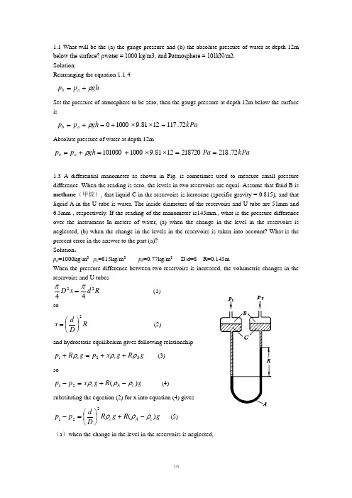
1.1 What will be the (a) the gauge pressure and (b) the absolute pressure of water at depth 12mbelow the surface? ρwater = 1000 kg/m3, and Patmosphere = 101kN/m2.Solution:Rearranging the equation 1.1-4gh p p a b ρ+=Set the pressure of atmosphere to be zero, then the gauge pressure at depth 12m below the surfaceiskPa gh p p a b 72.1171281.910000=⨯⨯+=+=ρAbsolute pressure of water at depth 12mkPa Pa gh p p a b 72.2182187201281.91000101000==⨯⨯+=+=ρ1.3 A differential manometer as shown in Fig. is sometimes used to measure small pressuredifference. When the reading is zero, the levels in two reservoirs are equal. Assume that fluid B ismethane (甲烷), that liquid C in the reservoirs is kerosene (specific gravity = 0.815), and thatliquid A in the U tube is water. The inside diameters of the reservoirs and U tube are 51mm and6.5mm , respectively. If the reading of the manometer is145mm., what is the pressure differenceover the instrument In meters of water, (a) when the change in the level in the reservoirs isneglected, (b) when the change in the levels in the reservoirs is taken into account? What is thepercent error in the answer to the part (a)?Solution :p a =1000kg/m 3 p c =815kg/m 3 p b =0.77kg/m 3 D/d=8 R=0.145mWhen the pressure difference between two reservoirs is increased, the volumetric changes in the reservoirs and U tubesR d x D 2244ππ= (1) so R D d x 2⎪⎭⎫ ⎝⎛= (2) and hydrostatic equilibrium gives following relationshipg R g x p g R p A c c ρρρ++=+21 (3)sog R g x p p c A c )(21ρρρ-+=- (4)substituting the equation (2) for x into equation (4) givesg R g R D d p p c A c )(221ρρρ-+⎪⎭⎫ ⎝⎛=- (5) (a )when the change in the level in the reservoirs is neglected,()Pa g R g R g R D d p p c A c A c 26381.98151000145.0)()(221=⨯-=-≈-+⎪⎭⎫ ⎝⎛=-ρρρρρ(b )when the change in the levels in the reservoirs is taken into account ()Pa g R g R D d g R g R D d p p c A c c A c 8.28181.98151000145.081.9815145.0515.6)()(22221=⨯-+⨯⨯⨯⎪⎭⎫ ⎝⎛=-+⎪⎭⎫ ⎝⎛=-+⎪⎭⎫ ⎝⎛=-ρρρρρρ error=%=7.68.2812638.281- 1.4 There are two U-tube manometers fixed on the fluid bed reactor, as shown in the figure. The readings of two U-tube manometers are R 1=400mm ,R 2=50mm, respectively. The indicating liquid is mercury. The top of the manometer is filled with the water to prevent from the mercury vapor diffusing into the air, and the height R 3=50mm. Try to calculate the pressure at point A and B .Solution: There is a gaseous mixture in the U-tube manometer meter. The densities of fluids are denoted by Hg O H g ρρρ,,2, respectively. The pressure at point A is given by hydrostatic equilibriumFigure for problem 1.4g R R g R g R p g Hg O H A )(32232+-+=ρρρg ρis small and negligible in comparison with Hg ρand ρH2O , equation above can be simplifiedc A p p ≈=232gR gR Hg O H ρρ+=1000×9.81×0.05+13600×9.81×0.05=7161N/m²1gR p p p Hg A D B ρ+=≈=7161+13600×9.81×0.4=60527N/m1.5 Water discharges from the reservoir through the drainpipe, which the throat diameter is d. The ratio of D to d equals 1.25. The vertical distance h between the tank A and axis of the drainpipe is 2m. What height H from the centerline of the drainpipe to the water level in reservoir is required for drawing the water from the tank A to the throat of the pipe? Assume that fluid flow is a potential flow. The reservoir, tank A and the exit ofdrainpipe are all open to air.Solution: Bernoulli equation is written between stations 1-1 and 2-2, with station 2-2 being reference plane: 2222222111u gz p u gz p ++=++ρρ Where p 1=0, p 2=0, and u 1=0, simplification of the equation22u Hg =1The relationship between the velocity at outlet and velocity u o at throat can be derived by the continuity equation:22⎪⎭⎫ ⎝⎛=⎪⎪⎭⎫ ⎝⎛D d u u o 22⎪⎭⎫ ⎝⎛=d D u u o 2 Bernoulli equation is written between the throat and the station 2-23 Combining equation 1,2,and 3 givesSolving for HH=1.39m1.6 A liquid with a constant density ρ kg/m 3 is flowing at an unknown velocity V 1 m/s through a horizontal pipe of cross-sectional area A 1 m 2 at a pressure p 1 N/m 2, and then it passes to a section of the pipe in which the area is reduced gradually to A 2 m 2 and the pressure is p2. Assuming no friction losses, calculate the velocities V 1 and V 2 if the pressure difference (p 1 - p 2) is measured. Solution :In Fig1.6, the flow diagram is shown with pressure taps to measure p 1 and p 2. From the mass-balance continuity equation , for constant ρ where ρ1 = ρ2 = ρ,222200u u p =+ρ()===144.281.92100081.910002125.11112442-⨯⨯⨯--⎪⎭⎫ ⎝⎛==ρρg h d D u Hg2112A A V V = For the items in the Bernoulli equation , for a horizontal pipe,z 1=z 2=0Then Bernoulli equation becomes, after substituting 2112A A V V = for V 2, ρρ22121211212020p A A V p V ++=++ Rearranging,2)1(21212121-=-A A V p p ρ ⎥⎥⎦⎤⎢⎢⎣⎡-⎪⎪⎭⎫ ⎝⎛-12221211A A p p V ρ=Performing the same derivation but in terms of V 2,⎥⎥⎦⎤⎢⎢⎣⎡⎪⎪⎭⎫ ⎝⎛--21221212A A p p V ρ=1.7 A liquid whose coefficient of viscosity is µ flows below the critical velocity for laminar flow in a circular pipe of diameter d and with mean velocity V . Show that the pressure loss in a length of pipe L p ∆ is 232d V μ. Oil of viscosity 0.05 Pas flows through a pipe of diameter 0.1m with a average velocity of 0.6m/s.Calculate the loss of pressure in a length of 120m.Solution :The average velocity V for a cross section is found by summing up all the velocities over the cross section and dividing by the cross-sectional area1From velocity profile equation for laminar flow2 substituting equation 2 for u into equation 1 and integrating3rearranging equation 3 gives1.8. In a vertical pipe carrying water, pressure gauges areinserted at points A and B where the pipe diameters are0.15m and 0.075m respectively. The point B is 2.5m belowA and when the flow rate down the pipe is 0.02 m 3/s, thepressure at B is 14715 N/m 2 greater than that at A.Assuming the losses in the pipe between A and B can be expressed as g V k 22where V is the velocity at A, find the value of k .If the gauges at A and B are replaced by tubes filled with water and connected to a U-tube containing mercury of relative density 13.6, give a sketch showing how the levels in the two limbs of the U-tube differ and calculate the value of this difference in metres.Solution:d A =0.15m; d B =0.075mz A -z B =l =2.5mQ =0.02 m 3/s,p B -p A =14715 N/m 2 Figure for problem 1.8 ⎰⎰==R R rdr u R udA A V 020211ππ⎪⎪⎭⎫ ⎝⎛⎪⎭⎫ ⎝⎛--=22014R r R L p p u L μ2032D L p p V L μ-=232d V L p μ=∆Pa d VL p 115201.01206.005.0323222=⨯⨯⨯==∆μsm d Q V V d Q AA AA /132.115.0785.002.044222=⨯===ππsm d Q V V d Q BB BB /529.4075.0785.002.044222=⨯===ππWhen the fluid flows down, writing mechanical balance equation222222AB B B AA A V k V g z p V g z p +++=++ρρ213.1253.4100014715213.181.95.2222k ++=+⨯k 638.0260.10715.14638.0525.24++=+=k 0.295making the static equilibriumgR g x g l p g R g x p Hg A B ρρρρρ+∆++=+∆+()()mm g g l p p R g H A B 7981.91260081.910005.214715-=⨯⨯⨯-=---=ρρρ1.9.The liquid vertically flows down through the tube from thestation a to the station b , then horizontally through the tube fromthe station c to the station d , as shown in figure. Two segments ofthe tube, both ab and cd ,have the same length, the diameter androughness.Find:(1)the expressions of g p ab ρ∆, h fab , g pcdρ∆and h fcd , respectively.(2)the relationship between readings R 1and R 2 in the U tube.Solution:(1) From Fanning equationFigure for problem 1.92V l h fab λ=andsoFluid flows from station a to station b , mechanical energy conservation giveshence2from station c to station dhence3From static equationp a -p b =R 1(ρˊ-ρ)g -l ρg 4p c -p d =R 2(ρˊ-ρ)g5 Substituting equation 4 in equation 2 ,thentherefore6Substituting equation 5 in equation 3 ,then7ThusR 1=R 222V d l h fcd λ=fcdfab h h =fab b a h p p+=+ρρlg fab b a h p p =+-lg ρfcddc h pp +=ρρfcd d c h p p =-ρfabh g l g R =+--'lg 1ρρρρ)(gR h fab ρρρ-'=1g R h fcd ρρρ-'=21.10 Water passes through a pipe of diameter d i=0.004 m with the average velocity 0.4 m/s, as shown in Figure.1) What is the pressure drop –∆P when water flows through the pipe length L =2 m, in m H 2O column?2) Find the maximum velocity and point r at which it occurs.3) Find the point r at which the average velocityequals the local velocity. 4)if kerosene flows through this pipe ,how do thevariables above change ?(the viscosity and density of Water are 0.001 Pasand 1000 kg/m 3,respectively ;and the viscosityand density of kerosene are 0.003 Pas and 800kg/m 3,respectively )solution:1)1600001.01000004.04.0Re =⨯⨯==μρud from Hagen-Poiseuille equation1600004.0001.024.0323222=⨯⨯⨯==∆d uL P μ m g p h 163.081.910001600=⨯=∆=ρ 2)maximum velocity occurs at the center of pipe, from equation 1.4-19max 0.5V u = so u max =0.4×2=0.8m3)when u=V=0.4m/s Eq. 1.4-172max 1⎪⎪⎭⎫ ⎝⎛-=wr r u u 5.0004.01max2=⎪⎭⎫ ⎝⎛-u V r = m r 00284.071.0004.05.0004.0=⨯== 4) kerosene:427003.0800004.04.0Re =⨯⨯==μρud Pa p p 4800001.0003.01600=='∆='∆μμFigure for problem 1.10m g p h 611.081.98004800=⨯=''∆='ρ1.12 As shown in the figure, the water level in the reservoir keeps constant. A steel drainpipe (with the inside diameter of 100mm) is connected to the bottom of the reservoir. One arm of the U-tube manometer is connected to the drainpipe at the position 15m away from the bottom of the reservoir, and the other is opened to the air, the U tube is filled with mercury and the left-side arm of the U tube above the mercury is filled with water. The distance between the upstream tap and the outlet of the pipeline is 20m.a) When the gate valve is closed, R=600mm, h=1500mm; when the gate valve is opened partly, R=400mm, h=1400mm. The friction coefficient λ is 0.025, and the lo ss coefficient of the entrance is 0.5. Calculate the flow rate of water when the gate valve is opened partly. (in m³/h)b) When the gate valve is widely open, calculate the static pressure at the tap (in gauge pressure, N/m²). l e /d ≈15 when the gate valve is widely open, and the friction coefficient λ is still 0.025.Solution :(1) When the gate valve is opened partially, the water discharge isSet up Bernoulli equation between the surface of reservoir 1—1’ and the section of pressure point 2—2’,and take the center of section 2—2’ as the referring plane, then∑+++=++21,2222121122—f h p u gZ p u gZ ρρ (a ) In the equation 01=p (the gauge pressure)222/396304.181.910004.081.913600m N gh gR p O H Hg =⨯⨯-⨯⨯=-=ρρFigure for problem 1.120021=≈Z uWhen the gate valve is fully closed, the height of water level in the reservoir can be related to h (the distance between the center of pipe and the meniscus of left arm of U tube).gR h Z g Hg O H ρρ=+)(12 (b )where h=1.5mR=0.6mSubstitute the known variables into equation b 2222_1,113.22)5.01.015025.0(2)(66.65.110006.013600V V V K d l h m Z c f =+⨯=+==-⨯=∑λ Substitute the known variables equation a9.81×6.66=2213.21000396302V V ++ the velocity is V =3.13m/sthe flow rate of water is h m V d V h /5.8813.312.0436004360032=⨯⨯⨯=⨯=ππ2) the pressure of the point where pressure is measured when the gate valve is wide-open. Write mechanical energy balance equation between the stations 1—1’ and 3-3´,then∑+++=++31,3233121122—f h p V gZ p V gZ ρρ (c ) since m Z 66.61=311300p p u Z =≈=2223_1,81.4 2]5.0)151.035(025.0[ 2)(V V V K d l l h c e f =++=++=∑λ input the above data into equation c ,9.8122V 81.4266.6+=⨯Vthe velocity is: V =3.51 m/sWrite mechanical energy balance equation between thestations 1—1’ and 2——2’, for the same situation of water level ∑+++=++21,2222121122—f h p V gZ p V gZ ρρ (d )since m Z 66.61=212103.51/0(page pressure Z u u m s p =≈≈=)kg J V K d l hc f /2.26251.3)5.01.015025.0(2)(222_1,=+⨯=+=∑λ input the above data into equationd , 9.81×6.66=2.261000251.322++p the pressure is: 329702=p1.14 Water at 20℃ passes through a steel pipe with an inside diameter of 300mm and 2m long. There is a attached-pipe (Φ60⨯3.5mm) which is parallel with the main pipe. The total length including the equivalent length of all form losses of the attached-pipe is 10m. A rotameter is installed in the branch pipe. When the reading of the rotameter is2.72m 3/h, try to calculate the flow rate in the main pipe and the total flow rate, respectively. The frictional coefficient of the main pipe and the attached-pipe is 0.018 and 0.03, respectively.Solution : The variables of main pipe are denoted by a subscript1, and branch pipe by subscript 2.The friction loss for parallel pipelines is2121S S s f f V V V h h +==∑∑The energy loss in the branch pipe is 22222222u d l l h e f ∑∑+=λ In the equation 03.02=λs m u d ml l e /343.0053.04360072.2053.01022222=⨯⨯===+∑πinput the data into equation ckg J h f /333.02343.0053.01003.022=⨯⨯=∑The energy loss in the main pipe is 333.022111121===∑∑u d l h h f f λ So s m u /36.22018.023.0333.01=⨯⨯⨯= The water discharge of main pipe ish m V h /60136.23.043600321=⨯⨯⨯=π Total water discharge ish m V h /7.60372.26013≈+=1.16 A Venturimeter is used for measuring flow of water along a pipe. The diameter of the Venturi throat is two fifths the diameter of the pipe. The inlet and throat are connected by water filled tubes to a mercury U-tube manometer. The velocity of flow along the pipe is found to beR 5.2 m/s, where R is the manometer reading in metres of mercury. Determine the loss of head between inlet and throat of the Venturi when R is 0.49m. (Relative density of mercury is 13.6). Solution:Writing mechanical energy balance equation between the inlet1 and throat o for Venturi meterf o o hg z V p g z V p +++=++22121122ρρ 1 rearranging the equation above, and set (z 2-z 1)=xf o oh xg V V p p ++-=-22121ρ 2 from continuity equationFigure for problem 1.1611221125.625V V d d V V o o =⎪⎭⎫ ⎝⎛=⎪⎪⎭⎫ ⎝⎛= 3 substituting equation 3 for V o into equation 2 gives()f f f f oh xg R h xg R h V h xg V V p p ++=++=+=++-=-94.1185.203.1903.19206.3922121211ρ 4from the hydrostatic equilibrium for manometerg x g R p p Hg o ρρρ+-=-)(1 5 substituting equation 5 for pressure difference into equation 4 obtainsf Hgh xg R gx g R ++=+-94.118)(ρρρρ 6 rearranging equation 6 kg J R R R R g R h Hg f /288.267.494.11861.12394.118)(==-=--=ρρρ1.17.Sulphuric acid of specific gravity 1.3 is flowing through a pipe of 50 mm internal diameter. A thin-lipped orifice, 10mm, is fitted in the pipe and the differential pressure shown by a mercury manometer is 10cm. Assuming that the leads to the manometer are filled with the acid,calculate (a)the weight of acid flowing per second, and (b) the approximate friction loss in pressure caused by the orifice.The coefficient of the orifice may be taken as 0.61, the specific gravity of mercury as 13.6, and the density of water as 1000 kg/m 3Solution: a)2.0501010==D D =⨯-=-=-81.9)130013600(1.0)(21g R p p Hg ρρ()s m p p D D C V o /63.231.461.056.1861.0130081.9)130013600(1.022.0161.021*******=⨯=≈⨯-⨯-=-⎪⎪⎭⎫ ⎝⎛-=ρs kg V D m /268.0130063.201.0442220=⨯⨯⨯==πρπb) approximate pressure drop=⨯-=-=-81.9)130013600(1.0)(21g R p p Hg ρρ12066.3Pa pressure difference due to increase of velocity in passing through the orificePa D D V V V V p p o 8.44882)2.01(63.213002242412222212221=-=⎪⎪⎭⎫ ⎝⎛-=-=-ρρ pressure drop caused by friction lossPa p f 5.75778.44883.12066=-=∆2.1 Water is used to test for the performances of pump. The gauge pressure at the discharge connection is 152 kPa and the reading of vacuum gauge at the suction connection of the pump is 24.7 kPa as the flow rate is 26m 3/h. The shaft power is 2.45kw while the centrifugal pump operates at the speed of 2900r/min. If the vertical distance between the suction connection and discharge connection is 0.4m, the diameters of both the suction and discharge line are the same. Calculate the mechanical efficiency of pump and list the performance of the pump under this operating condition.Solution:Write the mechanical energy balance equation between the suction connection and discharge connection 2_1,2222121122f H gp g u Z H g p g u Z +++=+++ρρ wherem Z Z 4.012=-(Pa 1052.1(Pa 1047.22_1,215241≈=⨯=⨯-=f H u u pressure gauge p pressure gauge p ))total heads of pump is m H 41.1881.9100010247.01052.14.055=⨯⨯+⨯+= efficiency of pump is N N e /=ηsince kW g QH N e 3.1360081.9100041.18263600=⨯⨯⨯==ρN=2.45kWThen mechanical efficiency %1.53%10045.23.1=⨯=η The performance of pump is Flow rate ,m³/h26 Total heads ,m18.41 Shaft power ,kW2.45 Efficiency ,%53.12.2 Water is transported by apump from reactor, which has200 mm Hg vacuum, to thetank, in which the gaugepressure is 0.5 kgf/cm 2, asshown in Fig. The totalequivalent length of pipe is200 m including all localfrictional loss. The pipeline isφ57×3.5 mm , the orificecoefficient of C o and orificediameter d o are 0.62 and 25mm, respectively. Frictional coefficient λ is 0.025. Calculate: Developed head H of pump, in m (the reading R of U pressure gauge in orifice meter is 168 mm Hg)Solution:Equation(1.6-9)Mass flow rates kg S V m o o /02.21000025.0414.312.42=⨯⨯⨯==ρ 2) Fluid flow through the pipe from the reactor to tank, the Bernoulli equation is as follows for V 1=V 2f H z gp p H +∆+-=ρ12 ∆z=10ms m Rg D d C V f /12.444.69375.062.01000)100013600(81.9168.025025162.02144000=⨯=-⨯⨯⎪⎭⎫ ⎝⎛-=-⎪⎭⎫ ⎝⎛-=ρρρ)(Pa p 7570710013.17602001081.95.054=⨯⨯+⨯⨯=∆ ∆p/ρg=7.7mThe relation between the hole velocity and velocity of pipeFriction losssoH=7.7+10+5.1=22.8m2.3 . A centrifugal pump is to be used to extract water from a condenser in which the vacuum is 640 mm of mercury, as shown in figure. At the rated discharge, the netpositive suction head must be at least 3m above the cavitation vaporpressure of 710mm mercury vacuum. If losses in the suction pipeaccounted for a head of 1.5m. What must be the least height of the liquid level in the condenser above the pump inlet?Solution :From an energy balance,WhereP o =760-640=120mmHgP v =760-710=50mmHgUse of the equation will give the minimum height H g as2.4 Sulphuric acid is pumped at 3 kg/s through a 60m length of smooth 25 mm pipe. Calculate the drop in pressure. If the pressure drop falls by one half, what will the new flowrate be ?• Density of acid 1840kg/m 3• Viscosity of acid 25×10-3 PasSolution:Velocity of acid in the pipe:s m D d V V /12112.42200=⎪⎭⎫ ⎝⎛⨯=⎪⎭⎫ ⎝⎛=m g u d l f H f 1.581.92105.0200025.02422=⨯⨯==NPSH H g p p H f v og ---=ρm NPSH H g p p H f v o g 55.335.181.9100081.913600)05.012.0-=--⨯⨯⨯-=---=(ρs m d m d mpipe of area tional cross flowrate volumetric u /32.3025.01840785.03785.04sec 222=⨯⨯===-=ρπρReynolds number:6109102532.31840025.0Re 3=⨯⨯⨯==-μρud from Fig.1.22 for a smooth pipe when Re=6109, f=0.0085 pressure drop is calculated from equation 1.4-9kg J u d l f ph f /450232.3025.0600085.042422=⨯==∆=ρ kPa p 5.8271840450=⨯=∆ or friction factor is calculated from equation1.4-25kg J u d l u d l f ph f /426232.3025.0606109046.042Re 046.042422.022.02=⨯⨯⨯==∆=--=ρkPa p 84.7831840426=⨯=∆ if the pressure drop falls to 783.84/2=391.92kPa8.18.12.12.038.12.12.022.0012.089.1079`2025.060102518401840046.042046.042Re 046.043919202u u u d l u d l p p =⎪⎭⎫ ⎝⎛⨯⨯⨯=⎪⎪⎭⎫ ⎝⎛⨯⨯⨯==∆='∆----ρμρρ= so s m u /27.236.489..1079012.03919208.18.1==⨯= new mass flowrate=0.785d 2u ρ=0.785×0.0252×2.27×1840=2.05kg/s2.4 Sulphuric acid is pumped at 3 kg/s through a 60m length of smooth 25 mm pipe. Calculate the drop in pressure. If the pressure drop falls by one half on assumption that the change of friction factor is negligible, what will the new flowrate be ?Density of acid 1840kg/m 3Viscosity of acid 25×10-3 Pa Friction factor 32.0Re 500.00056.0+=f for hydraulically smooth pipe Solution:Write energy balance equation:f h gu z g p H g u z g p +++=+++2222222111ρρ gu d l g p h H f 22λρ=∆== 342=ρπu ds m d u /32.31840025.014.3124322=⨯⨯=⨯=ρπ 611510251840025.032.3Re 3=⨯⨯⨯=- 0087.061155.00056.0Re 500.00056.032.032.0=+=+=f 92.4681.9232.3025.0600087.04222=⨯⨯==∆==g u d l g p h H f λρ Δp=46.92×1840×9.81=847.0kpa2.6 The fluid is pumped through the horizontal pipe from section A to B with the φ38⨯2.5mm diameter and length of 30 meters, shown as figure. The orifice meter of 16.4mm diameter is used to measure the flow rate. Orifice coefficient C o =0.63. the permanent loss in pressure is3.5×104N/m 2, the friction coefficient λ=0.024. find:(1) What is the pressure drop along the pipe AB?(2)What is the ratio of power obliterated in pipe AB to total power supplied to the fluid when the shaft work is 500W, 60%efficiency? (The density of fluid is 870kg/m 3 )solution :∑+++=+++f A A A A AA h u p g z w u p g z 2222ρρ ρλρ022p u d l h p p f BA ∆+==-∑ 247.0334.162=⎪⎭⎫ ⎝⎛=A A o()()s m gR C u /5.8870870136006.081.9297.063.02247.01200=-⨯⨯=''--=ρρρ ∴u = (16.4/33)2×8.5=2.1m/s∴242/76855105.321.2033.030870024.0m N h p p f B A =⨯+⨯==-∑ρ (2)W u d p Wm 1381.2033.0785.0768554Ne 22=⨯⨯⨯=∆==ρπρ sothe ratio of power obliterated in friction losses in AB to total power supplied to the fluid %%=461006.0500138⨯⨯3.2 A spherical quartzose particle (颗粒) with a density of 2650 kg/m³ settles (沉淀) freely in the 20℃ air, try to calculate the maximum diameter obeying Stocks ’ law and the minimum diameter obeying Newton’s law. Solution:The gravity settling is followed Stocks ’ law, so maximum diameter of particle settled can be calculated from Re that is set to 11Re ==μρt c t u d , thenρμc t d u = equation 3.2-16 for the terminal velocityμρρρμ18)(2g d d S c c -= solving for critical diameter32)(224.1g d S c ρρμ-=Check up the appendixThe density of 20℃ air ρ=1.205 kg/m³ and viscosity µ=1.81×10⁻³N ·s/m 2m md c μ3.571073.5205.1)205.12650()1081.1(224.15323=⨯=⨯-⨯=--when Reynolds number ≥1000, the flow pattern follows Newton ’s law and terminal velocity can be calculated by equation 3.2-19 ()ρρρ-=p p t gd u 75.1 1critical Reynolds number is1000Re ='=μρt ct u d , 2rearranging the equation 2 givesρμct d u '=1000 3 combination of equation 1 with equation 3 ρρρρμg d d S c c )(74.11000-'=' solving for critical diameter 32)(3.32μρρρ-='S cdummd c 151210512.1205.1)205.12650()1081.1(3.323323=⨯=⨯-⨯='--3.3 It is desired to remove dust particles 50 microns in diameter from 226.5m 3/min of air, using a settling chamber for the purpose. The temperature and pressure are 21o C and 1 atm. The particle density is 2403kg/m 3. What minimum dimensions of the chamber are consistent with these conditions? (the maximum permissible velocity of the air is 3m/s) solution:to calculate terminal velocity from the equation 3.2-16 ()μρρ182g d u p pt -=The density of 21℃ air ρ=1.205 kg/m³ and viscosity µ=1.81×10⁻⁵N ·s/m 2()s m g d u p pt /181.01081.11881.9)205.12403()1050(185262=⨯⨯⨯-⨯-=--=μρρ t BLu Q = so286.20181.0605.226m u Q BL t =⨯== 1 from equation3.3-4tu H u L = the maximum permissible velocity of the air is 3m/s181.03H L = H L 58.16= 2set B to be 3m , then from equation 1L =7mAndH =0.42m3.4 A standard cyclone is to be used to separate the dust of density of 2300 kg/m³ from the gas. The flow rate of gas is 1000m³/h, the viscosity of the gas is 3.6⨯10-5N ·s/ m², and the density is 0.674 kg/ m 3. If the diameter of cyclone is 400 mm, attempt to estimate the critical diameter. Solution:D =0.4mB =D /4=0.1mh =D /2=0.2ms m hB Q u i /9.131.02.036001000=⨯⨯==According to the equation3.3-12 for N=5:m m u N B d i p c μπρρπμ81089.13)02300(5)1.0)(106.3(9)(965=⨯=⨯-⨯≈-=--3.6 A filter press of 0.1m 2 filtering area is used for filtering a sample of the slurry. The filtration is carried out at constant pressure with a vacuum 500mmHg.The volume of filtrate collected in the first 5min was one liter and, after a further 5min, an additional 0.6 liter was collected. How much filtrate will be obtained when the filtration has been carried out for 15min on assuming the cake to be incompressible?Solution:The equation for the constant-pressure filtrationt KA VV V m 222=+5min .1l 51.02122⨯=+K V m10min .6.1l 101.06.126.122⨯⨯=⨯+K V msolving the equations above for V m and K7.0=m V and K =48For min 15=t 151.0487.0222⨯⨯=⨯⨯+V VSolving for V =2.073 l3.7 The following data are obtained for a filter press of 0.0093 m 2 filtering area in the testCalculate:(1) filtration constant K , V m at the pressure difference of 1.05(2) if the frame of the filter is filled with the cake at 660s, what is the final rate of filtration Edt dV ⎪⎭⎫ ⎝⎛ (3) and what is the compressible constant of cake n ?solution:①from equation 3.4-19aKt qq q m =+22 For pressure difference 05.1=p ㎏/㎝2500093.01027.220093.01027.2323⨯=⨯⨯+⎪⎪⎭⎫ ⎝⎛⨯--K q m 1 6600093.0101.920093.0101.9323⨯=⨯⨯+⎪⎪⎭⎫ ⎝⎛⨯--K q m 2 solving the equations 1 and 2 gives s m K m m q m /1056.10379.02323-⨯==②)(22m E V V KA dt dV +=⎪⎭⎫ ⎝⎛=s m /1014.736-⨯For pressure difference 5.3=p ㎏/㎝271.10093.01027.220093.01027.2323⨯'='⨯⨯+⎪⎪⎭⎫ ⎝⎛⨯--K q m 3 2330093.0101.920093.0101.9323⨯'='⨯⨯+⎪⎪⎭⎫ ⎝⎛⨯--K q m 4 solving the equations 3 and 4 gives s m K m m q m /1037.40309.02323-⨯='='n p p -⎪⎪⎭⎫ ⎝⎛∆'∆=K K '1 then n ---⎪⎭⎫ ⎝⎛=⨯⨯13305.15.31056.11037.433.3ln 8.2ln 1=-n solving for n =0.1423.8 A slurry if filtered by a filter press of 0.1m 2 filtering area at constant pressure, the equation for a constant pressure filtration is as follows)4.0(250)10(2+=+t qwhere q=filtrate volume per unit filtering area,in l/m 2, t= filtering time, in mincalculate:(1) how much filtrate will be gotten after249.6min?(2) If the pressure difference is double and both the resistances of the filtration medium and cake are constant, how much filtrate will be obtained after249.6min?solution:(1)22250)4.06.249(250)4.0(250)10(=+=+=+t qq=240 l/m 2V=24 l(2) the pressure difference is double2=∆'∆='pp K K soK ´=500210102=⎪⎪⎭⎫ ⎝⎛++'q q 2/5.3421025041.110)10(2m l q q =-⨯=-+='V=34.25 l3.9 Filtration is carried out in a plate and frame filter press, with 20 frames 0.3 m square and 50mm thick. At a constant pressure difference of 248.7kN/m 2, one-quarter of the total filtrate per cycle is obtained for the first 300s. Filtration is continued at a constant pressure for a further 1800s, after which the frames are full. The total volume of filtrate per cycle is 0.7 m 3 and dismantling and refitting of the press takes 500sIt is decided to use a rotary drum filter, 1.5m long and 2.2m in diameter, in place of the filter press. Assuming that the resistance of the cloth is the same and that the filter cake is incompressible, calculate the speed of rotation of the drum which will result in the same overall rate of filtration as was obtained with the filter press. The filtration in the rotary filter is carried out at a constant pressure difference of 70kN/m 2 and with 25% of the drum submergedSolution:Area of filtration: A =2×0.32×20=3.6m 2Δp =248.7kN/m 2t 1=300s, V 1=1/4×0.7=0.175m 3t 2-t 1=1800s, ΔV=0.7-0.175=0.525m 3or t 2 =2100s, V 2=0.7m 3 KV andKt KA V m m 21006.37.027.03006.3175.02175.022222⨯=⨯+⨯==⨯+V m =0.2627m 3 And 522101517.3210096.122627.04.149.021006.34.17.0-⨯=⨯⨯+=⨯+=m V K capacitys m Q /10692.250021007.034-⨯=+=for the rotary drum filter。

SmartLineIntroductionThe SMV800 combines sensor technologies for differential pressure, static pressure and temperature with the latest microprocessor technology to provide highly accurate data for measured variables, compensated flow and totalization over multiple communication protocols.When paired with the other SmartLine unique features the SMV 800 delivers the highest levels of safety, reliability and efficiency available resulting into reduced project costs and start-up time while improving the productivity. The SmartLine family is also fully tested and compliant with Experion ® PKS providing the highest level of compatibility assurance and integration capabilities. Best in Class Features: o Accuracy up to 0.0375% for Differential pressureo Accuracy up to 0.0375% for Static pressure o Accuracy up to 0.2 Deg C for Temperature o Mass Flow Reference Accuracy: up to 0.6% o Totalizer Reference Accuracy: up to 0.4%o Automatic static pressure & temperature compensation o Rangeability up to 400:1o Compensated flow response time of up to 2x per second o Multiple local display capabilitieso External zero, span, & configuration capability o Polarity insensitive electrical connections o Comprehensive on-board diagnostic capabilities o Integral Dual Seal design for highest safety based on ANSI/NFPA 70-202 and ANSI/ISA 12.27.0 o World class overpressure protection oModular design characteristicsCommunications/Output Options: o 4-20mA DC (Analog)o Honeywell Digitally Enhanced (DE) Single or Multivariable o HART ® (version 7.0)oModbus (RS-485, RTU) Half Duplex CommunicationAll transmitters are available with the above listed communication protocols.Figure 1 – SMV 800 Multivariable Transmitters featurefield-proven piezoresistive sensor technology Span & Range Limits:DescriptionHoneywell’s SM V 800 Smart Multivariable Flow Transmitter extends our proven “smart” technology to the measurement of three separate process variables with the ability to calculate compensated mass or volume flow rate as a fourth process variable according to industry standard methods for air, gases, steam and liquids. SMV800 HART and Modbus devices can also calculate total mass or volume flow.Unique Indication/DisplayAdvanced Graphics LCD Display Featureso Modular (may be replaced in the field)o0, 90, 180, & 270 degree position adjustmentso Standard and custom measurement units availableo Up to eight display screens with 3 formats are possible (Large PV with Bar Graph or PV with Trend Graph)o Configurable screen rotation timing (3 to 30 sec)o Display Square Root capabilities may be set separately from the 4-20mA dc output signal for HART & DEdeviceso Multiple language capability (EN, DE, FR, IT, ES, RU, TU, CH, & JP)DiagnosticsSmartLine transmitters all offer digitally accessible diagnostics which aid in providing advanced warning of possible failure events minimizing unplanned shutdowns, providing lower overall operational costs.Configuration ToolsIntegral Three Button Configuration OptionSuitable for all electrical and environmental requirements, SmartLine offers the ability to configure the transmitter and display via three externally accessible buttons except for the flow related parameters. Zero and span capabilities are also available optionally with HART and DE devices via three buttons with or without selection of a display option.Handheld ConfigurationSmartLine transmitters feature two-way communication and configuration capability between the operator and the transmitter. This is accomplished via Honeywell’s field-rated Configuration Toolkit (MCT404).The MCT404 is capable of field configuring HART and DE SMV devices for all parameters other than flow configuration, can be ordered for use in intrinsically safe environments.All Honeywell transmitters are designed and tested for compliance with the offered communication protocols and are designed to operate with any properly validated handheld configuration device.Measurement Types:SMV is capable of mass and volume flow measurements for liquids, gases, and superheated and saturated steam.Personal Computer ConfigurationHoneywell’s PC Based Configuration Toolkit SCT3000 provides an easy way to configure the SMV800 DE devices. SMV800 HART Device can be configured using Device Description based DCS Hosts and Asset Management Systems. HART devices can also be configured using PC based DTMs.Honeywell’s PC based configuration tool, ‘SmartLine Modbus Manager’ provides an easy and fast way to configure and troubleshoot the SMV Modbus devices including flow parameters. Configuration for multi-drop communication is also possible.SMV800 DTM and PC based applications provide enhanced features like:o Easy to use Flow Configurationo Units Preference: Configurable Engineering unitso Auto Calculation of Viscosity and DensityCoefficients, Auto Calculation of K User, Beta Factor o Export and Import Configurations to/from external file with predefine schema/formato Summary Page.Primary Element CompatibilityFLOW: The SMV is compatible with wide range of flow elements and provides dynamic calculation capabilities. SMV800 supports Advanced Algorithms and ASME 1989 Algorithms which is User selectable option in the DD / DTM Tools. Advanced Algorithm option supports the following Primary Elements with SMV800 HART, DE and Modbus Protocols:o Orifice Plates (ASME MFC-3M & AGA No 3/ISO 5167/GOST 8.586).o Integral Orificeo Small Bore Orifice (ASME MFC -14M)o Conditional Orifice (ISO5167-2003)o Nozzles (ASME MFC-3M/ISO 5167/GOST 8.586).o Venturi Tubes (ASME MFC-3M/ISO 5167/GOST).o Averaging Pitot Tubeso V-Cone®, Wafer Cone, Wedge.ASME 1989 Algorithm Option supports the following Primary Elements with SMV800 HART, DE and Modbus protocol:o Orifice (Flange Taps D >/= 2.3 inches, Flange Taps2 </= D </= 2.3, Corner Taps,Orifice D and D/2Taps, Orifice 2.5 and 8D Taps)o Venturi (Machined Inlet, Rough Cast Inlet, Rough Welded Sheet-Iron Inlet, Leopold, Gerand, VenturiTube, Low-Loss Venturi Tube)o Nozzle (Long Radius, Venturi Nozzle)o Various Preso Ellipse Pitot Tubes with varying Pipe Sizeso Other Pitot Tubes.Primary Element Compatibility, continuedFixed Parameters: Fixed Cd, Y1, Viscosity, Density are supported for user to customize the flow calculation.Temperature: The SMV also has the following temperature input options:o RTD (2,3,4 wires): PT25, PT100*, PT200, PT500, PT1000 (*DE models use only PT100 RTD)o Universal Input: RTD PT25, PT100, PT200, PT500, PT1000 and Thermocouple:Type B*, E, J, K, N*, R*, S*, T.*B, N, R, S Type inputs are only available with HART and Modbus protocols.Mass Flow CalculationMass Flow Compensation can be selected for Standard Compensations by user for Gas, Liquid and Steam without limitation on primary elements.Mass Flow Compensation can be selected for Dynamic Compensation by the user from:ASME-MFC-3M, ISO5167, Gost-8.586, for Orifice Plate, Nozzle and Venturri, AGA3 for Orifice, and Calculation Support for Averaging Pitot Tube, VCone, Wafer Cone, Wedge and Integral Orifice and Conditional Orifice are also available. Mass Flow Calculations also support user Fixed Input Parameters for Customizing the Calculations. System Integrationo SmartLine communications protocols all meet the most current published standards for HART, DE and Modbus o Integration with Honeywell’s Experion PKS offers the following unique advantages.o Messaging & Maintenance Mode Indication.o Tamper reporting.o FDM Plant Area Views with Health summaries.o All SMV 800 units are Experion tested to provide the highest level of compatibility assurance.Automatic Density CompensationUsing the configuration software, the SMV can be configured with the primary element type and the physical parameters of the fluid measured. This method dynamically compensates for fluid characteristics such as discharge coefficients, gas expansion factors, density, and viscosity as well as installation issues like upstream pipe size using the above referenced algorithms.Basic Flow Density CompensationThis conventional calculation method is based on flow factors being manually entered.Modular DesignTo help contain maintenance & inventory costs, all SMV 800 transmitters are modular in design supporting the user’s ability to replace meter bodies, indicators or change electronic modules without affecting overall performance or approval body certifications. Each meter body is uniquely characterized to provide in-tolerance performance over a wide range of application variations in temperature and pressure and due to the Honeywell advanced interface, electronic modules may be swapped without losing in-tolerance performance characteristics.Modular Featureso Meter body replacemento Replaceable electronics/comm modules*o Add or remove integral indicators*o Add or remove lightning protection (terminal connection) * * Field replaceable in all electrical environments (including IS) except flameproof without violating agency approvals. With no performance effects, Honeywell’s unique modularity results in lower inventory needs and lower overall operating costs. (Not available for Modbus)Performance SpecificationsDigital Reference Accuracy 2 (conformance to +/-3 Sigma)Zero and span may be set anywhere within the listed (URL/LRL) range limits Digital Accuracy at Specified Span, Temperature and Static Pressure (Combined Zero & Span,conformance to +/-3 Sigma)Typical Calibration Frequency:PV1 and PV2 calibration verification is recommended every four (4) years.Notes:1. Terminal based accuracy – Includes the combined effects of linearity, hysteresis and repeatability. Analog output adds 0.005% of span.2. For zero based spans and reference conditions of 25o C (77o F), 0 psig static pressure, 10 to 55% RH and 316SS barrier diaphragm.3. Static Line Pressure effect for SMA810 is % span/25 psi.Performance Specifications21. Digital Accuracy is accuracy of the digital value accessed by the Host system and the handheld communicator2. Analog Output Accuracy is applicable to the 4 to 20 mA Signal output3. For TC inputs, CJ accuracy of 0.25°C shall be added to digital accuracy to calculate the total digital accuracy4. These input types are only available with HART and Modbus protocolsTotal analog accuracy is the sum of digital accuracy and 0.005% of span.Ambient Temperature Effect Digital Accuracy: For RTD Inputs, 0.0015°C/°C/. For T/C Inputs: 0.005°C/°CAnalog Output: 0.0005% of span/°CPV4 Mass Flow Reference Accuracy: 0.6% of flow range, over 20:1 flow range, calculated every 500ms1,21. Flow performance specifications assume dynamic compensation and is applicable for SMA845 and SMG8702. Applicable standards and installations per ASME MFC 3M or ISO 5167-1 for un-calibrated orifice; Bigger than 2.8 inch Pipe Diameter;(0.2 < beta < 0.6 Orifice). DP Turn down 16:1; Reference accuracy does not include RTD sensor accuracy.1 LCD Display operating temperature -20 ︒C to +70 ︒C (-4 ︒F to 158 ︒F) . Storage temperature -30 ︒C to 80 ︒C (-22 ︒F to 176 ︒F). 2 For CTFE fill fluid, the rating is -15 to 110 ︒C (5 to 230 ︒F).3 Short-term equals 2 hours at 70 ︒C (158︒F).4MAWP applies for temperatures -40 ︒C to 125 ︒C (-40 ︒F to 257 ︒F). Static Pressure Limit is de-rated to 3,000 psi for -26︒C to -40︒C (-14.8 ︒F to -40 ︒F). Use of graphite O-rings de-rates transmitter to 3,625 psi. Use of ½” - process adaptors with graphite o-rings de-rates transmitter to 3,000 psi.5 Consult factory for MAWP of SMV 800 transmitters with CRN approval.6The MAWP is intended as a pressure safety limit. Honeywell does not recommend use above the PV2 Upper Range Limit.Figure 2 - Supply voltage and loop resistance chart & calculations (HART/DE Protocols)Materials Specifications1 Vent/Drains are sealed with Teflon®2 Hastelloy C-276 or UNS N10276.3 Monel 400 or UNS N04400.4 Supplied as 316 SS or as Grade CF8M, the casting equivalent of 316 SS.5 Carbon Steel heads are zinc-plated and not recommended for water service due to hydrogen migration. For that service, use 316stainless steel wetted Process Heads.6 Hastelloy C-276 or UNS N10276. Supplied as indicated or as Grade CW12MW, the casting equivalent of Hastelloy C-276.7 Monel 400 or UNS N04400. Supplied as indicated or as Grade M30C, the casting equivalent of Monel 400.Communications Protocols & DiagnosticsHART ProtocolVersionHART 7Power SupplyVoltage: 10.8 Vdc to 42.4 Vdc at terminalsLoad: Maximum 1440 ohms See Figure 2.Minimum Load: 0 ohms. (For handheld communications, a minimum load of 250 ohms is required) Honeywell Digitally Enhanced (DE)DE is a Honeywell proprietary protocol which provides multivariable DE communications between Honeywell DE enabled field devices and Hosts.Power SupplyVoltage: 15 Vdc to 42.4 Vdc at terminalsLoad: Maximum 900 ohms See Figure 2.Modbus ProtocolModbus provides easy integration of SMV devices with wide variety of host systems including Flow computers, RTUs, PLCs, Recorders, SCADA systems and supports multi-drop communication of up to 32 devices.Optional integral indicator can display up to 8 parameters cyclically including parameters from Flow computer, RTU or SCADA system.Low power consumption makes SMV Modbus transmitters ideal for solar powered installations.Power SupplyVoltage: 9.5V to 30 Vdc at terminals.Power Consumption: 70mW at 9.5V Supply.This includes RS-485 communication at 9600 baud rate once per second without termination at room temperature. Communication parameters.Standard DiagnosticsSMV 800 top-level diagnostics are reported as either critical or non-critical and readable via the DD/DTM tools or integral display as shown below.Note: For Modbus onlyHazardous Location Approval Certifications: HART and DE CommunicationsNotes1. Operating Parameters:Voltage= 11 to 42 V Current= 4-20 mA Normal (3.8 – 23 mA Faults)2. Intrinsically Safe Entity ParametersVmax= Ui= 30 V Imax= Ii = 225mA Ci =4 nF L i= 0 uH Pi = 0.9 WMODBUS CommunicationsOther Certification OptionsMaterialso NACE MRO175, MRO103, ISO15156Temperature Sensor Wiring DiagramFigure 3 – Temperature Sensor Wiring DiagramMounting & Dimensional DrawingsReference Dimensions:millimeters inchesFigure 4 – Mounting ConfigurationsFigure 5 – Typical mounting dimensions for reference20 SMV800 SmartLine Multivariable TransmitterModel Selection GuideModel Selection Guides are subject to change and are inserted into the specifications as guidance only.SMV800 SmartLine Multivariable Transmitter 2122 SMV800 SmartLine Multivariable TransmitterSMV800 SmartLine Multivariable Transmitter 23For more informationTo learn more about SmartLine Transmitters, visit Or contact your Honeywell Account ManagerProcess Solutions Honeywell2101 City West Blvd Houston, TX 77042Honeywell Control Systems LtdHoneywell House, Skimped Hill Lane Bracknell, England, RG12 1EB34-SM-03-92 November 2022©2022 Honeywell International Inc.Shanghai City Centre, 100 Jungi Road Shanghai, China 20061Sales and ServiceFor application assistance, current specifications, pricing, or name of the nearest Authorized Distributor, contact one of the offices below.ASIA PACIFICHoneywell Process Solutions, (TAC) hfs-tac-*********************AustraliaHoneywell LimitedPhone: +(61) 7-3846 1255 FAX: +(61) 7-3840 6481 Toll Free 1300-36-39-36 Toll Free Fax: 1300-36-04-70China – PRC - Shanghai Honeywell China Inc.Phone: (86-21) 5257-4568 Fax: (86-21) 6237-2826SingaporeHoneywell Pte Ltd.Phone: +(65) 6580 3278 Fax: +(65) 6445-3033South KoreaHoneywell Korea Co Ltd Phone: +(822) 799 6114 Fax: +(822) 792 9015EMEAHoneywell Process Solutions, Phone: + 80012026455 or +44 (0)1344 656000Email: (Sales)*************************** or (TAC)*****************************WebKnowledge Base search engine http://bit.ly/2N5VldiAMERICA’SHoneywell Process Solutions, Phone: (TAC) 1-800-423-9883 or 215/641-3610(Sales) 1-800-343-0228Email: (Sales)*************************** or (TAC)*****************************WebKnowledge Base search engine http://bit.ly/2N5VldiSpecifications are subject to change without notice.。
Flow sensors SFAHFlow sensors SFAHKey featuresAt a glanceCommunication interfaceUniversal flow measurement• 8 flow measuring ranges from 0.002 l/min to 200 l/min • High measuring dynamics (1:50)• Available as uni- or bidirectional• Excellent accuracy• Optional test reportQuick installation• No run-in sections required• Adjustable QS elbow connections• L1 and M8 plug for fast commissioningPractical design• Compact design 20x58 mm• Degree of protection IP40 or IP54Easy operation• Clear 2-line display• Configurable red surround for the entiredisplay• Intuitive menu navigation Switchable electrical outputs• Various switching functions• Switching outputs (PNP/NPN, NO/NC)• Analogue outputs (0…10 V, 1…5 V, 4…20 mA)Product description Area of application Functions IO-LinkThe flow sensor SFAH is suitable for monitoring compressed air andnon-corrosive gases. The sensor can be used in many industries thanks to its compact design. The method of meas-urement is based on the thermal heat-transfer method. The bypass con-struction means that it is less suscepti-ble to disruption by particles and moisture. The flow value is transmitted to the connected control system as a switching signal, as an analogue signal or via IO-Link®.• Process monitoring• Handling of extremely small parts• Monitoring of compressed airconsumption• Leak test• Monitoring of forming gas• Pneumatic object detection viaair-gap measurement• Monitoring and setting a flow ratethreshold, a flow rate range or achange in flow rate• Monitoring using the teach-infunction or by entering values• Mass flow rate and volumetric flowrate are displayed in the commonmeasurement units• ECO function with option to switchoff the display• Optional security code can be freelychosen (4-digit code)• Adjustable low-pass filter forsmoothing the flow signal• Scaling the analogue output toincrease the signal dynamics• Offset compensation possible• Min./max. value memory• All settings that have been enteredon one sensor (master) can betransferred (replication) to other,identical sensors (devices)• High pressure range –0.9 bar to10 bar• Serial communication integratedusing IO-Link 1.1• Cyclical transfer of two switchingstatuses and the measuredpressure value• The sensor can be parameterisedremotely using an IO-Link® master• Easy sensor replacement withautomatic parameterisation• Sensor identification, diagnosticsand teach-in possible via IO-Link Space-savingAdjustable QS elbow connections2d Internet: /catalogue/...Subject to change – 2022/0432022/04 – Subject to changed Internet: /catalogue/...Flow sensors SFAHKey featuresOrdering data – Product optionsConfigurable productThis product and all its p roduct options can be ordered using the configurator.The configurator can be found under Products on the DVD or atd /catalogue/…Part no. 8035300Type SFAHFlow sensors SFAHPeripherals overview4d Internet: /catalogue/...Subject to change – 2022/04Flow sensors SFAHType codes52022/04 – Subject to change d Internet: /catalogue/...6d Internet: /catalogue/...Subject to change – 2022/04Flow sensors SFAHData sheetFunction• Flow rate0.002 ... 0.1 l/min 0.01 ... 0.5 l/min 0.02 ... 1 l/min 0.1 ... 5 l/min 0.2 ... 10 l/min 1 ... 50 l/min 2 ... 100 l/min 4 ... 200 l/min• Maximum versatility and reduced warehousing thanks to switchable electrical outputs• Measuring signal filter for setting the rise time• Additional filter for smoothing thedisplay values1) For feature ...-B-...: The measuring range applies in both the positive and negative direction.2)For low leakage requirements in the lower measuring range, use G1/4 or G1/8 female thread in combination with pneumatic connection.1)In the pressure range –0.9 ... –0.7 bar, an additional pressure influence span of typically ±4% FS can be expected.Flow sensors SFAH Data sheet7 2022/04 – Subject to change d Internet: /catalogue/...Flow sensors SFAHData sheet8d Internet: /catalogue/...Subject to change – 2022/04Flow sensors SFAH Data sheet1)Protection to IP54 is provided in combination with a safety guard mounted horizontally as illustrated on page 3.2)With 6 bar at the input and q max.3)Corrosion resistance class CRC 2 to Festo standard FN 940070Moderate corrosion stress. Indoor applications in which condensation can occur. External visible parts with primarily decorative surface requirements which are in direct contact with a normal industrial environment.9 2022/04 – Subject to change d Internet: /catalogue/...Flow sensors SFAHData sheet10d Internet: /catalogue/...Subject to change – 2022/041)Suitable for the production of lithium-ion batteries:Metals with more than 1% by mass of copper, zinc or nickel are excluded from use. Exceptions are nickel in steel, chemically nickel-plated surfaces, printed circuit boards, cables, electrical plug connectors and coils.H-rail mountingSAMH-FH-H- ...Material: PA, POM, steelRoHS-compliantWall mountingSAMH-FH-W ...Material: Steel, high-alloy stainlesssteel, RoHS-compliant1)Corrosion resistance class CRC 2 to Festo standard FN 940070Moderate corrosion stress. Indoor applications in which condensation can occur. External visible parts with primarily decorative surface requirements which are in direct contact with a normal industrial environment.Panel mounting kitSAMH-FH-F- ...Material: PA, steel, high-alloy stainlesssteelRoHS-compliant1)Corrosion resistance class CRC 2 to Festo standard FN 940070Moderate corrosion stress. Indoor applications in which condensation can occur. External visible parts with primarily decorative surface requirements which are in direct contact with a normal industrial environment.Safety guardSACC-FH-G-S3Material: PA, RoHS-compliantOnly in combination with electrical connection M8.For degree of protection IP54, protection against splashing water from every direction to ISO 20653/DIN EN 60529 with horizontal mounting as illustrated on page 3.。
from MKS or other manufacturers.Key Benefits•Patented1 sensor design provides exceptional zero stability•Fast warm-up time minimizes expensive production downtime1U.S. Patent No. 5461913. Foreign Patents Pending.SpecificationsFull Scale Ranges (N2equivalent)10, 20, 50, 100, 200, 500, 1000, 2000, 5000, 10000, 20000 sccm Maximum Inlet Pressure150 psigNormal Operating Pressure Differential (with atmospheric pressure at the MFC outlet)• 10 to 5000 sccm: 10 to 40 psid • 10000 to 30000 sccm: 15 to 40 psidControl Range2% to 100% of Full Scale Accuracy (analog)(including non-linearity, hysteresis, and non-repeatability referenced to 760 mmHg and 0°C)±1.0% of F.S. Repeatability±0.2% of Reading Resolution0.1% of Full ScaleTemperature Coefficients Zero Span • <0.05% of Full Scale/°C • <0.08% of Reading/°CWarm-up Time (to within 0.2% of Full Scaleof steady state performance)<2 minController Settling Time(per SEMI Guideline E17-91)<2 secPressure Coefficient<0.02% of Reading/psi Normal Operating Temperature Range0°C to 50°CInput Voltage RequiredMax. current at start-up (first 2 sec) Typical current at steady state • ±15 VDC (±5%) @ 200 mA • ±15 VDC (±5%) @ 100 mASet Point Command Signal0 to 5 VDC from <20K ΩOutput Signal0 to 5 VDC into >10K ΩOutput Impedance<1 ΩConnector Types Analog9-pin or 15-pin Type “D” (The 15-pin Type “D” connector is electronically compatiblewith other MKS flow controllers. Consult Applications Engineering for details.)Wetted Materials Standard Optional (Seals and Valve Seat)• 316L S.S., Viton®, nickel • Buna-N, Neoprene®, Kalrez®Leak Integrity External (scc/sec He) Through closed valve • <1 x 10⁻⁹• <1.0% of F.S. at 40 psig inlet to atmosphere(To assure no flow-through, a separate positive shut-off valve is recommended.)Fittings (compatible with)Swagelok® 4 VCR®, Swagelok® 4 VCO®, ¼'' Swagelok®Compliance CEMKS products provided subject to the US Export Regulations. Export, re-export, diversion or transfer contrary to US law (and local country law) is prohibited. US Patent No 5461913. mksinst ™ is a trademark, Califlow ® and Mass-Flo ® are registered trademarks of MKS Instruments, Inc. or a subsidiary of MKS Instruments, Inc. All other trademarks cited herein are the property of their respective owners.1179C_08/21©2017-2021 MKS Instruments, Inc.Specifications are subject to change without notice.Ordering Code Example: 1179C00412CR1BVCodeConfigurationModel1179C Mass-Flo Controller1179C 1179CGas To Be Calibrated For: (SEMI Gas Code) See table for additional optionsH eliumArgonH ydrogenNitrogenOxygen001004007013015004Flow Rate To Be Calibrated For SCCM (Maximum 20000 SCCM N 2 Equivalent)10 20 50 100 200 500 1000 2000 5000 10000 2000011C 21C 51C 12C 22C 52C 13C 23C 53C 14C24C12CFittings (compatible with)Swagelok 4 VCR maleSwagelok 4 VCO male 1/4'' Swagelok R G S RValveNormally Closed 11ConnectorAnalog 9 pin Type “D” Analog 15 pin Type “D”A B BSeal Materials Viton Buna-N Neoprene KalrezV B N KVOptional Accessories946 Multi-channel power supply/readout/set point control CablingCB147-12-10 to connect 1179C 9-pin Type “D” to 946 and cables100016744/45/46 to connect 1179C 15-pin Type “D” to 946 and cables Dimensional Drawing — Unless otherwise specified, dimensions are nominal values in inches (mm referenced).SEMI Gas CodeName Symbol Maximum FS, sccm Flow Rate 001Helium He 30,00034C 004Argon Ar 30,00034C 007HydrogenH 220,00024C 008Air --20,00024C 013Nitrogen N 220,00024C 015Oxygen O 220,00024C 019Chlorine Cl 210,00014C 025Carbon DioxideCO 210,00014C 028Methane CH 410,00014C 029Ammonia NH 310,00014C 039Silane SiH 410,00014C 042Acetylene C 2H 210,00014C 110Sulfur HexaFluorideSF 65,00053C。
store operating data for offline analysis.Key Benefits•Device configuration and diagnostics made simple through standard Ethernet interface •Uses a standard web browser with no specialsoftware requiredNT I NU E DUnless otherwise specified, dimensions are nominal values in inches (mm referenced). *See manual for additional I/O and fitting types.Digital I/OProfibus ®PROFINET ®Input Power Required +15 to +24 VDC (< 4 watts)+24 VDC (< 5 watts)Connector•9 pin Type D male (power)•9 pin Type D female (comm.) 2 x RJ-45 (comm.) male, M8 male, 5 pin (power)Data Rate Switch/Selection •No switch•Set data rate via Profibus No switch Comm. Rate(s)9.6 Kbps to 12 Mbps 100 Mbps MAC ID Switches/Addresses 2 switches, 10 positions N/A Network SizeUp to 99 nodesN/A Visual Indicators •LED Comm (green/red)•LED Error (green/red)•LED Maint (amber)•LED BUS Fault (red)•LED Ready (green)•LED Sys Fault (red)ComplianceCE •CEFitting Code Fitting NameOverall Length D 8 VCO Male 6.78''M ½'' NPT Female 7.36''S ½'' Compression 6.35''T 8 VCR Male 7.20''H 9/16-18 UNF6.22''W ½'' Compression Long 8.25''L 8 VCR Male Long 8.63''J 3/8'' Compression 6.34''F 12mm Compression 6.34''Q8 VCO Male Long8.31''DI SCO N T I N U E DMKS products provided subject to the US Export Regulations. Export, re-export, diversion or transfer contrary to US law (and local country law) is prohibited. mksinst ™ is a trademark of MKS Instruments, Inc. or a subsidiary of MKS Instruments, Inc. All other trademarks cited herein are the property of their respective owners.IE250A_11/21©2015-2021 MKS Instruments, Inc.Specifications are subject to change without notice.Ordering InformationOrdering Code Example: IE250A013255TBV0020CodeConfigurationModelMFC High Flow Mass Flow Controller (multi-gas, multi-range)IE250AIE250AGas*Name Helium Argon Hydrogen Air Nitrogen Code 001004007008013Formula He Ar H 2Air N 2Min/Max Full Scale (slm) 140 to 350140 to 250100 to 250100 to 250100 to 250001004007008013013Flow Range Full Scale**250 slm (250,000 sccm)255255Fittings (compatible with)12 mm Swagelok 3/8'' Swagelok½'' tube compression ½'' Compression Long ½'' NPT female 8 VCR Male 8 VCO Male8 VCR Male Long 8 VCO Male Long W-SealF J S W M T D L Q H TConnector (Power & Control I/O)Profibus ® (1480 Compatible) Profibus (1179B Compatible)PROFINET15 pin D (Analog 0 to 5 VDC I/O) 15 pin D (4 to 20 mA I/O)439B H BSeal Material Viton BunaNeoprene EPDMViton (USP Class VI Compliant)V B N E WVValve/Device Type Normally Closed Mass Flow Meter030Reserved for MKS Future Use Standard 00FirmwareUnless otherwise specified, MKS will ship firmware revision current to date.2020* For gases not listed in the standard products gas table, please contact the MKS applications department for assistance.** The Full Scale flow rate is designated by a 3 digit number. The first two digits represent the significant digits of the Full Scale flow rate separated by a decimal point. The third digit is the exponent of the power of ten. Example flow rate code: 255 is 2.5 x 10⁵ sccm or 250 slm; 105 is 1.0 x 10⁵ sccm or 100 slmDI SCONT IN UE D。