打印机维修手册:T1100部件手册
- 格式:pdf
- 大小:1.26 MB
- 文档页数:8
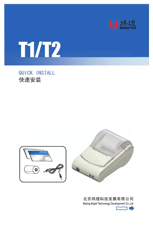
QUICK INSTALL 快速安装 北京炜煌科技发展有限公司Beijing Bright Technology Development Co.,Ltd快速安装手册●打印机各部件一览 Printer Parts Names1.纸仓盖 Paper Case Cover2.机头盖 Panel3.SEL 键 SEL Button4.LF 键 LF Button5.纸仓 Paper Case6.色带/打印头 Ribbon/ Printer head7.指示灯 Indicator Light 8.备用接口 Reserve Case 9.数据接口 Interface Connector 10.电源接口 Power Connector按钮开关的操作及指示灯打印机上电后电源指示灯保持常亮状态,状态指示灯常亮为正常待机状态,即在线,打印机可接收数据,不亮为离线状态,不能接收数据。
热敏型打印机缺纸时灯闪,不能接收数据。
SEL 键切换打印机在线离线,离线状态下LF 键为走纸键。
自检测方式打印机上电之后,按SEL 键使打印机离线(新针打和热敏型省略此步骤),按住LF 键不放,接着按下SEL 键,同时放开LF 键和SEL 键,即打出自检条。
Operation SpecificationAfter turning on the printer, the indicator light is on, shows that the printer is online, and it is ready to receive data. The light is off, shows that the printer is offline, and it can not receive data. When the light flash to show the paper is lacking, and the printer can not receive data.The SEL button can switch online or offline status. When the printer is offline, press the LF button, and the printer will feed paper.The Self TestTurn on the printer, press the SEL button to make printer offline (when use new dot matrix printing and thermal printing model, no need to refer this step), press the LF button, and don ’t release, then press the SEL button, and then release the both two buttons at the same time,and then the printer will print out the self-check scrip.快速安装手册●尺寸 SizeWH-T1/T2型尺寸 Product Size:外形尺寸:Outline Dimension: 180mm×110mm×90mm 挂孔孔距:Installation Hole Distance: 93.5mm●安装 Installation安装方法:打印机挂在设备上。
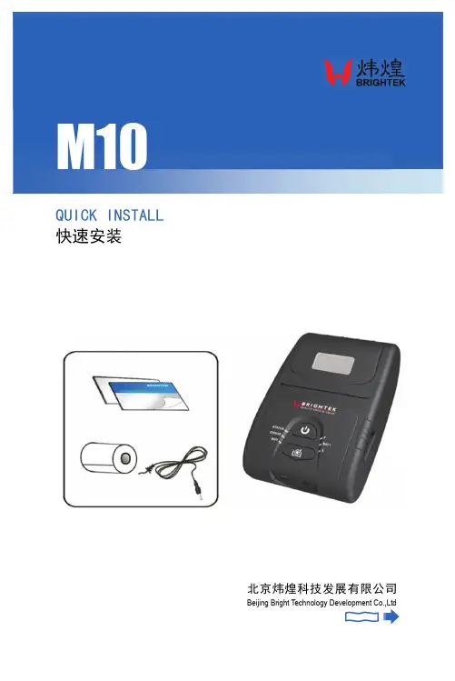
QUICK INSTALL 快速安装 北京炜煌科技发展有限公司Beijing Bright Technology Development Co.,Ltd●打印机各部件一览 Printer Parts Names1.滚轴 Platen Roller2.纸仓盖 Paper Case Cover3.纸卷 Paper Roll4.纸仓开关 Lock5.电源开关 Power Button6.指示灯 Indicator Light7.LF 键 LF Button8.WIFI 复位键 Reset Button9. USB 接口 Interface Connector 10.充电电源接口 Power Connector 11.电池 Battery 12.背夹 Clip按钮开关的操作及指示灯开机:打印机按住电源开关3秒钟,电源打开。
工作状态指示灯闪亮。
少于3秒钟电源不动作。
关机:在开机状态,按压电源开关3秒钟,电源关闭,工作状态指示灯熄灭。
少于3秒钟电源不动作。
走纸:按压走纸键(LF 键),按下开始进纸,放开停止进纸。
自检测方式关机状态下按压走纸键(LF)键,然后开机,可以打印自检。
Operation SpecificationAfter press the power button and hold on for 3 seconds, then the power is on. The status indicator flashes. In the power-on state, press the power button and hold on for 3 seconds, then the power is off. The status indicator light turns off.Press the paper feed button (LF button), the printer starts feeding paper. If release the button, it will stop feeding paper.The Self TestIn the power-off state, press the paper feed button (LF button), notrelease and power on. Then the printer will print self-check scrip.●尺寸 SizeWH-M10型尺寸 Product Size:外型尺寸 Outline Dimension: 134mm×86mm×56.7mm 打印纸规格 Paper Size:纸类型 Paper Type厚度Thickness宽度width纸卷直径Diameter热敏纸Thermal Paper0.06-0.08mm57±0.5mm Max 50mm●安装Installation安装方法:1、装电池,将电池下端两个卡位插入打印机内,并用力将另一端扣入即可。
第七章常见问题解答本章帮助您检查并解决在使用万全T100 1020服务器系统的过程中可能遇到的问题。
如果您在使用过程中遇到未在手册中出现的新问题,请及时拨打800-810-8888免费咨询热线求助。
7.1 系统第一次启动服务器第一次启动产生的问题通常是由于运输环境恶劣导致硬件连接松脱或损坏部分硬件引起的。
如果出现问题,建议用户按以下步骤检查:1、服务器的硬件配置是否与装箱单一致?2、所有的电缆是否都连接正确并接牢?3、处理器是否完全插入主板的插槽中?4、CPU散热片是否正常工作?5、所有的PCI插卡是否完全插入主板的插槽中并牢固?6、为确保用户自己添加的插卡可以应用,应检查是否存在资源冲突,例如:两块插卡是否共享同一中断?7、所有的外部设备如光驱、软驱是否可以正常使用?8、如果系统有一个硬盘,它是否已进行格式化或配置?9、所有的设备驱动是否安装正确?10、用户是否自己更改BIOS设置导致系统不能正常运行?11、操作系统装入是否正确?可参阅操作系统相关文档。
12、是否已按前面板上的系统电源按钮开启服务器(通电灯指示应该亮)?13、系统电源线是否与系统正确连接并插入插座?14、如果这些项目都正确但问题仍然发生,参见后面的介绍或与代理商联系。
7.2 运行新的应用软件在运行一个新的应用软件时产生的问题通常与软件有关。
尤其是在其它软件运行正确的情况下,由设备硬件引起的故障可能性比较小。
如果出现问题,建议用户按以下步骤检查:1、系统是否满足软件对硬件的最低要求?请参阅软件的随机文件。
2、软件是否为合法软件?如果不是,换一个;未授权的复制软件经常运行不正常。
3、如果从一张软盘上运行软件,它是否是一个完好的拷贝?1694、如果从光盘上运行软件,光盘是否有污损?5、如果从一个硬盘驱动器上运行软件,软件的安装是否正确?是否遵循所有的操作并安装了所有的文件?6、设备驱动程序安装是否正确?7、软件的配置是否正确?8、是否正确地使用软件?9、如果这些项目都正确但问题依然存在,请与软件商的客户服务代表联系。


一:清EEPROM 及其它面板操作速查(打印机内存全清)1.针打系列LQ-300k+换行/换页+进纸/退纸+暂停+电源LX-300+换行/换页+进纸/退纸+暂停+电源LQ-580K :换行/换页+进退纸+暂停+电源.LQ-630K :清EEPROM:换行/换页+进退纸+暂停+电源. 设置: 进纸/退纸 + 暂停 + 电源键盘锁定: 换行/换页 + 暂停 + 5秒以上,响二声。
解锁: 进纸/退纸 + 换行/换页 + ON.LQ-670K:高速+切纸电+源LQ-680K :换行/换页+进纸/退纸+暂停+电源LQ-1600K3/K3+,2600K字体+切纸+电源LQ-1600K4/K4+字体+切纸+电源LQ-2600K字体 + 切纸 + 电源DLQ-1000KLine Feed + Form Feed + Micro Adjust ↓ + 电源DLQ-3000K清EEPROM :Selec Type + Paper Select + Pause + 电源DLQ-3500KLF/FF + Load/Eject + Pause + 电源2.喷墨系列COLOR切换 + 字体 + 进/退纸 + 暂停+电源COLOR II切换+暂停+进纸+彩清洗+电源中国专业办公技术论坛h t t p ://w w w .o a c h n .n e tCOLOR 300进纸+清洗+电源, 再按清洗10秒COLOR 400/440/460进纸灯闪几秒后,按 1、 进/退纸清EEPROM 2、 清洗10秒,清废墨计数器COLOR 500进纸 + 黑头清洗 + 彩头清洗 + on ,再按进纸键3秒COLOR 600/640/66O/670进纸+清洗+电源 缺纸灯闪5秒后,再按1、进/退纸清EEPROM及timer IC2、清洗10秒,清废墨计数器COLOR 800/850初始化:进纸+黑头清洗+彩头清洗+ON ,松手再按彩头清洗10秒COLOR 1520K切换+进/退纸+换行/换页+微调↑+ 电源COLOR 3000暂停 + 换行/换页 + 微调↓ + 电源SP870/1270进/退纸 + 清洗 + on 然后按1、 /退纸清EEPROM及timer IC2、 清洗10秒,清废墨计数器SP 950:Paper + Roll paper + on 1. Paper (EEPROM)SP 2100/2200Paper + Roll paper + on 1. Paper (EEPROM)MJ-510进/退纸 + 清洗 + on 松手后再按进/退纸10秒至进纸灯和缺墨灯闪MJ-850切换 + 暂停 + 电源, 再按进/退纸至省墨灯与暂停灯闪烁,再按切换MJ-1000切换 + 省墨/压缩 + 进/退纸 + 暂停 + 电源MJ-1500K/K+切换+微调↓+暂停+换行/换页+ONproxl(xl+) alt +font+load/eject+pause+开机stylus1000 切换+省墨/压缩+进纸/退纸+暂停+开机中国专业办公技术论坛h t t p ://w w w .o a c h n .n e tEPSON 彩喷机需清零的机型分以下几种:1。


EPSON-TM系列打印机主板维修手册TM-U210打印机一、主板组成部分:从大的方面来说,可以分为打印主板和连接板两部分。
其中打印主板又可以分为以下几部分:1、控制部分CPU(U5 TMP90CS39F ):CPU是主板的核心,故称之为中央处理器。
负责整机系统的控制,对各部件进行统一的协调和控制。
它的功能有:进行算术逻辑运算,可接收和发送数据,可暂存少量的数据,提供控制信号,对指令解码。
flash EEPROM(U101 TC58F401FT-90):可擦除可编程在电脑里可以被重写,它的功能:1。
自检及初始化,开机后flash EEPROM最先被启动,然后它会对打印机的硬件设备进行完全彻底的检验和测试。
2。
.程序服务:flash EEPROM直接与I/O(Input/Output,即输入/输出)设备打交道,通过特定的数据端口发出命令,传送或接收各种外部设备的数据,实现软件程序对硬件的直接操作。
地址锁存器(U7 74LS373)它的功能是,使数据的地址信号分开。
2、电源部分电源部分主要由CN1,F1,L1,D6,R114,U200等组成。
U200的功能是将输入的34V电压转换为5V电压,提供IC及部件所需的电压。
3:驱动部分驱动部分主要由:QM1,QM2,QM3,QM4,(MP4020),Q114,Q115(D2204)组成。
(QM 三极管堆,用于放大和调整驱动信号)。
各自负责的接口如下:QM1,QM2------CN7-----打印头QM3-------CN5------字车马达(用于移动打印头)QM4-------CN6----- 进纸马达Q114,Q115---------CN2-----钱箱以上的指令均由CPU(U5 TMP90CS39F)发出。
二、常见的故障及解决方法:1、打印头不出针,打印空白将万用表档位打到二极管档,用红表笔接QM1的第1脚,用黑表笔分别接另外9个脚,测量它们之间的阻值。
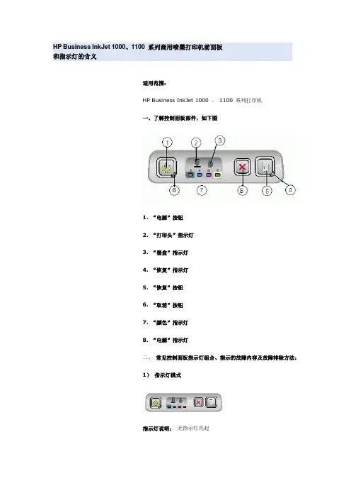
HP Business InkJet 1000、1100 系列商用喷墨打印机前面板和指示灯的含义适用范围:HP Business InkJet 1000 、1100 系列打印机一、了解控制面板部件,如下图1. “电源”按钮2. “打印头”指示灯3. “墨盒”指示灯4. “恢复”指示灯5. “恢复”按钮6. “取消”按钮7. “颜色”指示灯8. “电源”指示灯二、常见控制面板指示灯组合、指示的故障内容及故障排除方法:1)指示灯模式说明及建议操作:打印机关闭。
∙按( 电源按钮).2)指示灯模式指示灯说明:“电源”指示灯亮起。
说明及建议操作:∙打印机就绪, 无需进行任何操作3)指示灯模式指示灯说明:“电源”指示灯闪烁。
说明及建议操作:打印机正在打开或关闭,或正在处理一项打印作业,或取消了一项打印作业。
∙无需进行任何操作。
4)指示灯模式指示灯说明:“电源”指示灯亮起,“恢复”指示灯闪烁。
说明及建议操作:打印机的纸张用完了。
∙装入纸张,然后按( 恢复按钮) 。
打印机处于手动双面打印模式。
它正在等待墨水晾干,这样才能将纸张翻转,然后重新装入打印机。
∙将这叠纸重新装入打印机,然后按( 恢复按钮) 。
打印机暂停,等待墨水晾干。
∙等待墨水晾干。
“恢复”按钮将停止闪烁。
打印机已打印好一张条幅纸,需要从打印机中取出条幅纸。
∙按( 恢复按钮) 从打印机中取出条幅纸。
未安装自动双面打印单元。
不安装它,打印机无法打印。
∙安装自动双面打印单元,然后按( 恢复按钮) 。
5)指示灯模式指示灯说明:“电源”指示灯和“恢复”指示灯同时闪烁。
说明及建议操作:∙按( 恢复按钮) 以弹出卡住的介质。
∙取出出纸盘中的所有介质。
打开顶盖,找到被卡住的介质并清除按( 恢复按钮) 继续执行打印作业。
∙打开顶盖,用酒精清洁金属导轨并涂抹少许润滑油( 缝纫机油或钟表油即可) 。
6)指示灯模式指示灯说明:“电源”指示灯闪烁,“恢复”指示灯亮起。
说明及建议操作:打印机的一个或多个盖板未盖好。
佳能S100SP维修资料重写清零A、不安装墨盒,按RESET键通电源B、释放RESET键,5秒内重按一次C、打开前盖,安装黑色墨盒D、关上前门双击RESET键,打印机此时开始测试打印。
E、完成测试后,要拨电源才能再次打印按RESET键听到呜叫2声或以上时松手,此时清洗开始。
s200sp <<<<<<A、不安装墨盒,按RESET键通电源B、释放RESET键,5秒内重按一次C、打开前盖,安装黑色墨盒D、关上前门双击RESET键,打印机此时开始测试打印。
E、完成测试后,要拨电源才能再次打印>>>>>佳能S300维修模式1.关机.按住RESUME键,按住POWER键开机,绿灯亮.2.在按住POWER键时,松开RESUME键,然后按RESUME键2次,松开POWER键,(按住PESUME键时指示灯绿/黄闪烁)3.初始化操作时,绿灯闪烁,绿灯亮后,根据下表RESUME键.4.按POWER键,执行.按键次数: 指示灯: 维修模式功能:1次黄灯亮出厂检测打印2次绿灯亮EEPROM信息打印5次黄灯亮目标设置6次绿灯亮PTH值打印目标设置:选择模式设置,按POWER键,根据下表按PESUME键,然后按POWER键:按键次数: 目标:1次海外(S300)2次日本(BJS300)CANON S4001、最大幅面:A42、分辩率:1440*7203、所用墨水盒:BC-30e 1150页/墨水盒、160个喷嘴BC-33e (BCI-3eBK/3Ec/3eM/3eY)分别为(1520/55)页每个墨水盒、BC-34ephoto(BCI-3Epbk/3ePC/3Epm/3Epy)分别为(920/380/210/450)页/墨水盒4、打印速度:9张/分(黑墨盒)、4张/分(彩墨盒)5、操作系统:WIN95/98/2000、NT4.0、Mac (双平台)6、打印缓存:128KB7、接口:并口(IEEE1284、ECP)、USB8、维修功能:(用户可排除故障)供纸错黄灯闪2次卡纸错黄灯闪3次墨水用完黄灯闪4次错误安装墨盒黄灯闪5次无墨盒黄灯闪6次小车错黄灯闪7次废墨警告黄灯闪8次(用户不可排除故障)ROM错黄1/绿1灯交替闪RAM错黄2/绿1灯交替闪EEPROM错黄3/绿1灯交替闪6800原位错黄4/绿1灯交替闪5100温度传感器错黄5/绿1灯交替闪5400废墨满错黄6/绿1灯交替闪5B00打印头温度过高黄7/绿1灯交替闪5200打印头温度传感器错黄8/绿1灯交替闪5200小车错位黄9/绿1灯交替闪5600供纸传感器错黄10/绿1灯交替闪57009、EEPROM重置:C 按RESUME键的同时按下POWER键不放手。
2.Reconnect the residual-toner feed motor connector J63 and connector J155 on the DC controller PCA.3.Perform the TCU Motor test. Under Diagnostics/Component Test, select TCU Motor and press OK. If this testfails, replace the Residual Toner Feed Motor, part number RM1-5605-000CN.4.If the issue persists, check the gears and ducting of the Waste Toner Paper Feed assembly. If the gears are wornout, replace this component, part number RM1-5584-000CN.top59.C0 ErrorDescriptionDeveloper disengaging (alienation) motor rotation errorRecommended action1.Reconnect intermediate connector J87 of the developing disengagement sensor (SR11), connector J112 on theDC controller PCA, connector J38 of the developing disengagement motor, and the connector J261 on the high-voltage power supply D PCA.2.Run the manual sensor test to verify that the developing disengagement sensor (SR11) is functioning properly.NOTE: SR11 cannot be manually toggled. See Service Manual, Chapter "Manual sensor test (special-modetest)" for instructions.If it is not, replace the main-drive assembly.3.Run the component test for the developing disengagement (alienation) motor (M10) to verify that thedisengagement mechanism is functioning properly. If it is not, replace the developing disengagement motor(M10).top59.F0 ErrorDescriptionA 59.F0 error message is displayed on control panel when the product boots up.CauseThis behavior is primarily caused by a transfer alienation failure in which the ITB is stuck and unable to rotate or because the SR9 sensor (the primary transfer-roller-disengagement sensor aka Sensor K) has gone bad.Recommended actionUpdate to the latest available firmware at .If the issue persists, reseat the ITB, check the connections, perform manual and diagnostic flag and sensor tests, test the fuser motor, and then test the alienation mechanism:1.Reseat the ITB.2.Check the connections to primary transfer-roller-disengagement sensor (SR9 at connector J19) and to the DCcontroller PCA (connector J128).3.If the issue persists, remove the ITB completely from the unit and manually test the ITB gear and flag.1.Rotate the gear and check that the flag actuates when the white gear is turned.Figure 13: Rotate the ITB gear to actuate the ITB flagFigure 14: Flag moving as gear rotatesIf the ITB flag is broken or damaged, or if the flag does not move, replace the ITB.4.If the ITB gear and flag are working properly, test Sensor SR9 by using the MANUAL SENSOR TEST andmanually testing the SR9 flag.1.Remove the ITB if it has been re-installed and locate Sensor SR9 inside the ITB cavity.Figure 15: Primary transfer-roller-disengagement sensor SR9 (Sensor K)2.On the control panel, press the Home button, press the down arrow to highlight the DIAGNOSTICSmenu and press OK, and then select MANUAL SENSOR TEST and press OK.3.From inside the ITB cavity, press up and then release the SR9 flag to actuate the sensor.Figure 16: Manually activating Flag to actuate Sensor SR94.While pressing and releasing the flag, check the control panel display for sensor response (under K) andconfirm that the sensor toggles between 0 and 1 (0 is the normal state).5.If the value does not toggle between 0 and 1, replace the sensor (WG8-5696-000CN).NOTE: To stop the diagnostic, press OK, select EXIT DIAGNOSTICS, and then press OK.5.If Sensor SR9 is working properly, perform a fuser motor (M2) COMPONENT TEST.1.Remove the Fuser.2.Defeat the right door safety switch (upper left area) by inserting a stiff or folded piece of paper anddefeat the right door logic switch (right side below fuser) by using masking tape to hold switch down.3.On the control panel, press the Home button, press the down arrow to highlight the DIAGNOSTICSmenu and press OK, select COMPONENT TEST and press OK, and then select FUSER MOTOR andpress OK.4.During the test, observe the fuser motor gear.5.If the test fails or the fuser motor gear does not rotate, replace the fuser motor (M2).NOTE: To exit the diagnostic, select EXIT DIAGNOSTICS and then press OK.6.If the fuser motor is working properly, perform an ITB Contact/ Alienation Test.NOTE: This test activates the fuser motor (M2) and primary transfer solenoid (SL1) to cycle through the ITBalienation stages.1.Defeat the right door safety switch (upper left area) by inserting a stiff/folded piece of paper and thendefeat right door logic switch (right side below fuser) by use masking tape to hold switch down.2.On the control panel, press the Home button, press the down arrow to highlight the DIAGNOSTICSmenu and press OK, select COMPONENT TEST and press OK, and then select ITB Contact/ AlienationTest and press OK.3.During the test, observe the alienation drive hub located above the cyan cartridge.4.If the test fails or the alienation drive hub does not rotate, replace the fuser-drive assembly.NOTE: To exit the diagnostic, select EXIT DIAGNOSTICS and then press OK.7.Check the connections again to the primary-transfer disengagement sensor J19 and to the connector J128 on theDC controller PCA before reinstalling the ITB.8.Remove any items used to defeat the right door switches, reinstall the ITB and any other components removedduring testing.9.If the error still persists, replace the DC Controller.top60.02 ErrorDescriptionTray 2 is not lifting correctly.。
EPSON ME OFFICE 1100简明维修手册 EBTS技术支持科 V1.0 目 录 -产品性能和参数 1.1产品规格……………………………………………………………………………………………… 2 1.2墨盒规格……………………………………………………………………………………………… 3 1.3双黑墨使用规则和状态监视器墨量显示…………………………………………………………… 4 1.4目标用户与前续产品C110的比较 ………………………………………………………………… 5 -面板功能及操作 2.1面板外观 …………………………………………………………………………………………… 5 2.2按键功能……………………………………………………………………………………………… 6 2.3面板指示灯对应的打印机状态……………………………………………………………………… 7 -机械结构以及主要部件 -3.1机械结构……………………………………………………………………………………………… 8 -3.2主要部件……………………………………………………………………………………………… 9 -机器拆装注意事项 4.1拆卸顺序……………………………………………………………………………………………… 10 4.2拆卸图示……………………………………………………………………………………………… 11 -维修调整 5.1调整程序……………………………………………………………………………………………… 40 5.2拆装、更换备件所需做的调整……………………………………………………………………… 42 -用户使用FAQ 用户使用FAQ……………………………………………………………………………………………… 43 - 维修案例……………………………………………………………………………………………………… 44 一、 产品性能和参数 1.1产品规格 Ø最高打印分辨率: 5760×1440dpi (带有智能墨滴变换技术),多至5种墨滴尺寸。