GDSlab2.5操作手册中文版6q-HCA应力路径加载模块
- 格式:pdf
- 大小:328.51 KB
- 文档页数:4

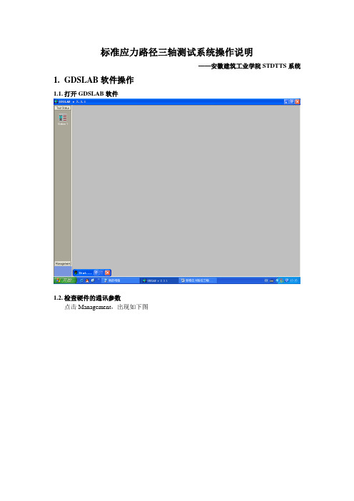
标准应力路径三轴测试系统操作说明——安徽建筑工业学院STDTTS系统1.GDSLAB软件操作1.1.打开GDSLAB软件1.2.检查硬件的通讯参数点击Management,出现如下图并点击Object Display,出现系统硬件的连接图,8通道数据采集板Comm Port: 1Baud: 4800Parity: n(此处必须为None,否则无法正常通讯,这一点很重要)Data Bits: 8Stop Bits: 2设置上面的参数后,就开始设置压力/体积控制器 STDDPC V2,包括反压、轴压和围压的通讯参数,点击“Select STDDPC controller”,会弹出“GDS USB controller selection tool ”,然后选择下拉菜单下的文件,从3个控制器的通讯文件选择一个,之后点击“Selected”,系统就会为反压控制器选择通讯文件。
图29为反压控制器通讯设置正常后的状态。
轴向压力/体积控制通讯参数跟反压一样,当反压和轴向控制器选好后,一定要注意控制器与压力室的链接情况。
当三个图标的通讯参数设置好以后,就点击“Read”图标,查看各个传感器是否有读数。
注意,本系统在已经选好通讯文件,一般情况下,如果不出现系统错误,不需要再进行设置,只需要在实验前检查下就可以了。
在每个控制器后面有个序列号,反压为12813,轴压为12811,围压为12809,注意检查控制器与压力室管路连接是否正确。
选择控制的通讯文件STDDPC V2 连接状态1.3.传感器和控制器清零在装土样前,要对传感器和控制器清零1.3.1. 传感器清零,只能在软件上清零点击某个传感器所对应的眼睛图标,会出现对话框,点击Advanced,然后在“Soft Zero Offset”旁边点击“Set Zero”,观察传感器的读数就会变成0。
如果出现很小的波动为正常。
轴向力、孔压和轴向位移传感器清零都是如此。
1.3.2. 控制器清零需要在控制器上操作,否则会造成控制器上显示的读数跟软件显示的不一致。

GDSLAB V2 GDS 软件操作用户手册© GDS Instruments Ltd, 2003关于本手册GDSLAB用户手册按照逻辑分为几个章节。
每个章节的开始有一页目录详细显示该章节的具体内容。
1 简介对GDSLAB软件进行简单介绍,包括设计理念和软件内容。
2 安装一步一步指导安装GDSLAB Kernel模块和其它模块。
3 运行一个试验说明一般情况下如何运行试验。
解释对所有试验都通用的原理。
• 选择硬件初始化文件• 选择、输入数据和开始一个试验图形界面4 GDSLAB介绍GDSLAB图形界面。
该章节简单浏览一下GDSLAB图形界面,解释相关窗口和菜单。
• GDSLAB 工具栏5 配置您的试验站硬件显示单个试验站点和详细介绍如何配置。
• 站点目标显示• 传感器标定系数设定6 试验模块This section describes the test procedures according to particular test modules. Not all available test modules may feature in this manual. For a full list of test modulescurrently available for GDSLAB contact GDS Instruments directly or see 本节主要介绍每个试验模块的试验过程。
不是所有的试验模块都会详细介绍。
如要了解详细的试验模块内容,请直接与GDS仪器设备有限公司联系或浏览获得详细信息。
简介 1 概述GDSLAB软件主要用于岩土试验控制和/或数据采集。
GDSLAB的设计就是为了让设备可以很容易地与PC机相连接(例如:通过RS232,IEEE,USB),以及与其它设备相连接(例如;与其它厂家的设备相连接)。
1 简介GDSLAB软件对岩土试验控制软件来说是一个突破。

EC-Lab 软件用户手册目 录录1. 介绍 (6)2. EC-Lab软件:设置 (7)2.1 开始程序 (7)2.2 EC-Lab软件准备和运行实验 (9)2.2.1 EC-Lab主界面 (9)2.2.1.1 设置工具栏 (9)2.2.1.2 图表工具栏 (11)2.2.1.3 状态工具栏 (11)2.2.1.4 当前值工具栏 (12)2.2.1.5 参数设定框架 (12)2.2.1.6 右击“Parameter settings”窗口 (13)2.2.2 菜单栏 (14)2.2.3 选择协议 (17)2.2.4 参数设定:详细流程图 (18)2.2.5 选择设置图表的纵列显示 (22)2.2.6 池特性 (22)2.2.6.1 标准“Cell Characteristics”窗口 (23)2.2.6.2 纵列形式的池特性窗口 (24)2.2.6.3 电池“Cell Characteristics”窗口 (24)2.2.7 高级设置 (26)2.2.7.1 规则 (26)2.2.7.2 电极连接 (27)2.2.7.3 实验限制 (28)2.2.7.4 文本导出 (28)2.2.7.5平滑处理 (28)2.2.7.6 每次生成一个数据文件 (28)2.2.8 接受和保存设置 (29)2.2.9 运行获取数据 (29)2.3 运行中的可变命令 (30)2.3.1 停止和暂停 (30)2.3.2 进程中更改实验 (30)2.4 多通道选择:一组或同步通道 (31)2.5 批处理模式 (32)2.6 数据特征 (33)2.6.1 数据文件类型 (33)2.6.2 变量描述 (34)2.6.3 数据记录 (36)2.6.4 数据保存 (36)2.7 更改通道拥有者 (37)2.8 组成选项 (37)2.8.1 常规选项 (37)2.8.2 警告选项 (39)2.8.3 文本导出选项 (40)2.8.4 颜色选项 (40)2.8.5 参比电极选项 (41)2.8.6 协定选项 (42)2.8.7 工具栏选项 (43)3. EC-Lab软件:图表显示 (44)3.1 图表窗口 (44)3.1.1 图表窗口右击菜单 (44)3.1.2 加载数据文件 (46)3.1.3 EC-Lab图表显示 (48)3.1.4 图表工具栏 (49)3.1.5 数据文件和规则选择窗口 (49)3.2 图表工具 (51)3.2.1 周期/循环显示 (51)3.2.2 显示/隐藏点 (53)3.2.3 在图表中添加注释 (53)3.2.4 图表特性 (55)3.2.5 日志(历史)文件 (59)3.2.6 复制选项 (60)3.2.6.1 标准复制选项 (60)3.2.6.2 高级复制选项 (60)3.2.7 打印选项 (61)3.2.8 多图表窗口 (61)3.2.8.1 在一个窗口中多个图表 (61)3.2.8.2 多窗口 (62)3.3 图表工具:拟合和分析 (63)3.3.1 区域选择 (64)3.3.2 线性拟合 (64)3.3.3 圆形拟合 (65)3.3.4 Stern和Geary模型 (66)3.3.5 Rp拟合 (67)3.3.6 Tafel拟合 (68)3.3.6.1 Tafel拟合窗口 (69)3.3.6.2 腐蚀率 (71)3.3.6.3 最小化选项 (71)3.3.7 积分 (72)3.3.8 最小值和最大值确认 (73)3.3.9 峰分析 (74)3.3.9.1 基线选择 (74)3.3.9.2 峰分析结果 (75)3.3.9.2.1 用线性衰减基线的峰分析结果 (76)3.3.9.2.2 用多项式基线的峰分析结果 (76)3.3.10 波分析 (78)3.3.11 Mott-Schottky拟合 (79)3.3.11.1 半导体Mott-Schottky关系和特性 (79)3.3.11.2 Mott-Schottky规则 (80)3.3.11.3 Mott-Schottky拟合 (81)3.3.12 曲线平滑处理 (82)3.3.13 保存拟合和分析结果 (83)3.4 数据和文件处理 (83)3.4.1 数据处理 (84)3.4.1.1 处理选项 (85)3.4.1.2 导数处理 (86)3.4.1.3 压缩过程 (87)3.4.1.4 每个周期电容和能量 (88)3.4.1.5 每个协议和周期的概述 (89)3.4.1.6 恒功率协议概述 (90)3.4.1.7 极化电阻 (91)3.4.1.8 多腐蚀统计 (91)3.4.2 文件处理 (91)3.4.2.1 生成和导出ASCII文本文件 (91)3.4.2.2 从其他电化学软件导入ASCII文本文件 (92)3.4.2.3 FC-Lab数据文件导入 (94)3.4.2.4 ZSimpWin导出 (94)3.5 阻抗数据分析:模拟、拟合和Kramers-Kronig规则 (94)3.5.1 电等效元素:描述 (94)3.5.1.1 电阻:R (95)3.5.1.2 电感:L (96)3.5.1.3 电容:C (96)3.5.1.4 等相元素:Q (97)3.5.1.5 Warburg元素用于半无限扩散:W (97)3.5.1.6 Warburg元素用于对流扩散:Wd (98)3.5.1.7 线性扩散元素:M (98)3.5.1.8 Gerischer元素:G (99)3.5.2 模拟:Zsim (100)3.5.2.1 ZSim窗口 (100)3.5.2.2 电路选择 (102)3.5.2.3 描述编码 (102)3.5.3 拟合:ZFit (104)3.5.3.1 Zfit选择窗口 (105)3.5.3.2 拟合方法 (105)3.5.3.3 应用 (107)3.5.3.4 连续循环上的拟合 (108)3.5.3.5 准电容 (109)3.5.3.6 附加规则 (111)3.5.4 Kramers-Kronig关系 (112)3.6 报告 (114)4. 连接实验 (116)4.1 描述和设置 (116)4.2 阶跃电位EIS实验应用 (117)5. 高级的特点 (121)5.1 标准通道板最大电流范围限制(2.4A) (121)5.1.1 不同的限制 (121)5.1.2 GSM电池测试的应用 (122)5.2 电位控制分辨率的最优化 (123)5.2.1 电位控制范围(跨度) (124)5.2.2 工作电位窗口设置 (125)5.3 测量对控制电流范围 (125)5.3.1 电位模式 (126)5.3.2 电流模式 (126)5.3.3 在电流模式中的1A电流范围特性 (127)5.3.4 在实验中多电流范围选择 (127)5.4 外接设备控制和记录 (128)5.4.1 概述 (128)5.4.2 旋转电极控制 (130)5.4.2.1 连接 (130)5.4.2.2 控制面板 (131)5.4.3 温度控制 (132)5.4.4 电化学石英晶体微天平耦合 (133)5.5 电化学实验前的预处理方法 (135)5.5.1 平衡态确立 (135)5.5.2 预处理方法 (135)5.5.2.1 机械的更改 (135)5.5.2.2 电化学更改 (135)5.5.3 电化学测量前用于预处理的EC-Lab工具 (136)6. 发现并维修故障 (137)6.1 数据保存 (137)6.2 PC不能连接 (137)6.3 电脑保存选项对数据记录的作用 (137)7.术语表 (138)8. 索引1. 介绍EC-Lab 软件的设计用于控制我们所有的恒电位仪(单通道或多通道:MPG ,VMP ,VMP2(Z),BiStat ,VMP3,VSP ,HCP-803,EPP-400和EPP-4000)。
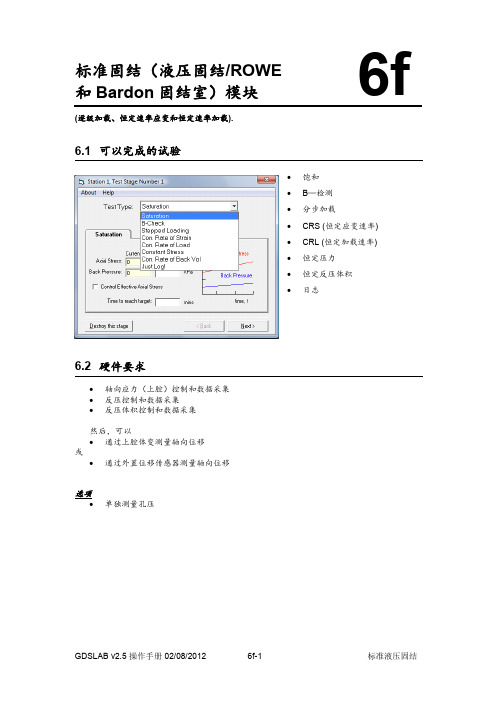
标准固结(液压固结/ROWE 和Bardon 固结室)模块(逐级加载、恒定速率应变和恒定速率加载).6.1 可以完成的试验∙ 饱和 ∙ B —检测 ∙ 分步加载∙ CRS (恒定应变速率) ∙ CRL (恒定加载速率) ∙ 恒定压力 ∙ 恒定反压体积 ∙ 日志6.2 硬件要求∙ 轴向应力(上腔)控制和数据采集∙ 反压控制和数据采集∙ 反压体积控制和数据采集然后,可以∙ 通过上腔体变测量轴向位移 或∙ 通过外置位移传感器测量轴向位移选项∙ 单独测量孔压6f6.3 试验过程从站点试验计划(Station Test Plan)窗口中的添加试验阶段(Add Test Stage)面板上选择试验控制模块:StandardHydrocon.dll点击创建新试验阶段(Create New Test Stage)按钮,打开试验阶段详细菜单(Test Stage Details)。
选择要求的试验类型,可以是和B—检测、分步加载、CRS (恒定应变速率)、CRL (恒定加载速率)、恒定压力、恒定反压体积或者日志。
6.3.1 饱和饱和试验使您可以独立地增加或降低轴压(有效应力)和反压。
饱和速率主要用于在指定的时间内稳定压力增加速率。
.饱和速率窗口(如下图)将显示系统中当前轴向应力(或有效应力)和反压。
输入要求的目标围压,反压和要求达到这些目标压力的时间。
.点击下一步(Next)进入设置终止选项(见6.3.9节)6.3.2 B—检测由于在CRS 和R&B 试验中试样受到环刀的侧向约束,所以标准固结中的B—检测不能够运用于传统意义上的Skempton B-检测。
与固结试验中检测试样饱和度不同,标准固结根据轴向应力的改变进行判断。
在反压立体保持不变的同时轴向应力增加到指定的值(例如不排水状态)。
系统检测轴向应力改变值()引起额孔隙水压力的改变值()。
标准固结的B-检测值即为。
下面的B-检测窗口将显示当前的孔隙水压力和轴向应力、输入轴向应力的目标值。

Flammable Gas Sensor(Model:MP-5)ManualVersion: 1.3Valid from: 2014-05-01Zhengzhou Winsen Electronics Technology Co., LtdStatementThis manual copyright belongs to Zhengzhou Winsen Electronics Technology Co., LTD. Without the written permission, any part of this manual shall not be copied, translated, stored in database or retrieval system, also can’t spread through electronic, copying, record ways.Thanks for purchasing our product. In order to let customers use it better and reduce the faults caused by misuse, please read the manual carefully and operate it correctly in accordance with the instructions. If users disobey the terms or remove, disassemble, change the components inside of the sensor, we shall not be responsible for the loss.The specific such as color, appearance, sizes &etc, please in kind prevail.We are devoting ourselves to products development and technical innovation, so we reserve the right to improve the products without notice. Please confirm it is the valid version before using this manual. At the same time, users’ comments on optimized using way are welcome.Please keep the manual properly, in order to get help if you have questions during the usage in the future.Zhengzhou Winsen Electronics Technology CO., LTD.Tel: 86-371-67169097 / 67169670 Fax: 86-371-60932988 Email: *******************MP-5 Flammable gas SensorProfileMP-5 gas sensor is for flammable gases. It adopts multilayer thick film manufacturing technology. The heater and metal oxide semiconductor material on the ceramic substrate of subminiature Al 2O 3 are fetched out by electrode down-lead, encapsulated in metal socket and cap. Conductivity of the sensor is affected by the concentration of target gas. The higher the concentration is, the higher conductivity of sensor gets. Users can adopt simple circuit to convert variation of conductivity into output signal corresponding to gas concentration.Features:* Lower consumption * Small size* Fast response and resume * Highest sensitivity* Excellent stability and long life * Easy circuit and big signal output *Excellent selectivityApplicationIt is widely used in domestic gas leakage alarm, industrial flammable gas alarm and portable gas detector.Technical ParametersTel: 86-371-67169097 / 67169670 Fax: 86-371-60932988 Email: *******************Basic circuitInstructions: The above fig is the basic test circuit of MP-5.The sensor requires two voltage inputs: heater voltage (V H ) and circuit voltage (V C ). V H is used to supply standard working temperature to the sensor and it can adopt DC or AC power, while V RL is the voltage of load resistance R L which is in series with sensor. Vc supplies the detect voltage to load resistance R L and it should adopts DC power.Description of Sensor CharactersFig5.Response and ResumeFig6.Linearity curveFig3.Typical Sensitivity Curve The ordinate is resistance ratio of the sensor (Rs/R 0), the abscissa is concentration of gases. Rs means resistance in target gas with different concentration, R 0 means resistance of sensor in clean air . All tests are finished under standard test conditions.Fig4.Typical temperature/humidity characteristicsThe ordinate is resistance ratio of the sensor (Rs/Rso).Rs means resistance of sensor in 2000ppm propane (C 3H 8) under different tem. and humidity. Rso means resistance of the sensor in 2000ppm propane (C 3H 8) under 20℃/65%RH.时间(S) C 3H 8Air CH 4 AlcoholTime (s)Concentration (ppm) Output voltage ( V)Tel: 86-371-67169097 / 67169670 Fax: 86-371-60932988 Email: *******************Long-term StabilityTest is finished in standard test conditions, the abscissa is observing time and the ordinate is V RL .Cautions1 .Following conditions must be prohibited1.1 Exposed to volatilizable organic silicon steamSensing material will lose sensitivity and never recover if the sensor absorbs organic silicon steam. Sensors must be avoided exposing to silicon bond, fixature, silicon latex, putty or plastic contain silicon environment. 1.2 High Corrosive gasIf the sensors are exposed to high concentration corrosive gas (such as H 2S, SO X , Cl 2, HCl etc.), it will not only result in corrosion of sensors structure, also it cause sincere sensitivity attenuation. 1.3 Alkali, Alkali metals salt, halogen pollutionThe sensors performance will be changed badly if sensors be sprayed polluted by alkali metals salt especially brine, or be exposed to halogen such as fluorine.1.4 Touch waterSensitivity of the sensors will be reduced when spattered or dipped in water.1.5 FreezingDo avoid icing on sensor’s surface, otherwise sensing material will be broken and lost sensitivity. 1.6 Applied higher voltageApplied voltage on sensor should not be higher than stipulated value, even if the sensor is not physically damaged or broken, it causes down-line or heater damaged, and bring on sensors’ sensitivity characteristic changed badly. 1.7 Voltage on wrong pinsAs Fig8. Pin 1&2 connects to heater circuit, Pin 3&4 connects to measuring circuit; Under the requested conditions, heating and measuring can use the same power circuit. NOTE: the two pins near the protuberance mark is heating electrode.Time (day)Output voltage ( V)Pin 1&2 is heating electrode,Pin 3&4 is measuring electrode.Protuberance MarkFig8.Pin Schematic Diagram2 .Following conditions should be avoided2.1 Water CondensationIndoor conditions, slight water condensation will influence sensors’ performance lightly. However, if water condensation on sensors surface and keep a certain period, sensors’ sensitiv e will be decreased.2.2 Used in high gas concentrationNo matter the sensor is electrified or not, if it is placed in high gas concentration for long time, sensors characteristic will be affected. If lighter gas sprays the sensor, it will cause extremely damage.2.3 Long time storageThe sensors resistance will drift reversibly if it’s stored for long time without electrify, this drift is related with storage conditions. Sensors should be stored in airproof bag without volatile silicon compound. For the sensors with long time storage but no electrify, they need long galvanical aging time for stability before using. The suggested aging time as follow:Stable2.2.4 Long time exposed to adverse environmentNo matter the sensors electrified or not, if exposed to adverse environment for long time, such as high humidity, high temperature, or high pollution etc., it will influence the sensors’ performance badly.2.5 VibrationContinual vibration will result in sensors down-lead response then break. In transportation or assembling line, pneumatic screwdriver/ultrasonic welding machine can lead this vibration.2.6 ConcussionIf sensors meet strong concussion, it may lead its lead wire disconnected.2.7 Usage Conditions2.7.1For sensor, handmade welding is optimal way. The welding conditions as follow:Tel: 86-371-67169097 / 67169670 Fax: 86-371-60932988 Email: *******************●homothermal soldering iron●Temperature:250℃●Time:less than 3 seconds2.7.2If users choose wave-soldering, the following conditions should be obey:●Soldering flux: Rosin soldering flux contains least chlorine●Speed: 1-2 Meter/ Minute●Warm-up temperature:100±20℃●Welding temperature:250±10℃●One time pass wave crest welding machineIf disobey the above using terms, sensors sensitivity will be reduced.Zhengzhou Winsen Electronics Technology Co., LtdAdd: No.299, Jinsuo Road, National Hi-Tech Zone,Zhengzhou 450001 ChinaTel: +86-371-67169097/67169670Fax: +86-371-60932988E-mail:*******************Website:Tel: 86-371-67169097 / 67169670 Fax: 86-371-60932988 Email: *******************。
LabVolt SeriesDatasheet Industrial Controls Double-Rail Workstation585964 (3105-B0)* The product images shown in this document are for illustration purposes; actual products may vary. Please refer to the Specifications section of each product/item for all details. Festo Didactic reserves the right to change product images and specifications at any time without notice.Festo Didactic en12/2023Industrial Controls Double-Rail Workstation, LabVolt SeriesTable of ContentsGeneral Description_________________________________________________________________________________3 Manual___________________________________________________________________________________________3 Specifications______________________________________________________________________________________3Industrial Controls Double-Rail Workstation, LabVolt SeriesGeneral DescriptionThe Industrial Controls Single-Rail Workstation consists of two pairs of mounting rails designed to be installed on top of the Workstation, Model 8134, or Mobile Workstation, Model 8110, to facilitate interconnection between the Industrial Controls Training Systems, Series 8036, and the Electric Power Technology Training Systems, series 8010.A safety bar is attached to each rail of the Industrial Controls Double-Rail Workstation. These bars prevents students from removing modules during laboratory exercises. Padlocks are provided to lock the safety bars in place once all modules are inserted in the workstation.ManualDescription Manual numberIndustrial Controls Training Systems Series 3100 (User Guide) ______________________________583973 (27073-E0) SpecificationsParameter ValuePhysical CharacteristicsIntended Location Installed on top of a Workstation, Model 8134, or Mobile Workstation, Model 8110Dimensions (H x W x D)427 x 935 x 85 mm (16.8 x 37.4 x 3.3 in)Net Weight11.3 kg (25 lb)Industrial Controls Double-Rail Workstation, LabVolt Series Reflecting the commitment of Festo Didactic to high quality standards in product, design, development, production, installation, and service, our manufacturing and distribution facility has received the ISO 9001 certification.Festo Didactic reserves the right to make product improvements at any time and without notice and is not responsible for typographical errors. Festo Didactic recognizes all product names used herein as trademarks or registered trademarks of their respective holders. © Festo Didactic Inc. 2023. All rights reserved.Festo Didactic SERechbergstrasse 373770 DenkendorfGermanyP. +49(0)711/3467-0F. +49(0)711/347-54-88500Festo Didactic Inc.607 Industrial Way WestEatontown, NJ 07724United StatesP. +1-732-938-2000F. +1-732-774-8573Festo Didactic Ltée/Ltd675 rue du CarboneQuébec QC G2N 2K7CanadaP. +1-418-849-1000F. +1-418-849-1666。
myLab User Guide: Safety ArrayInspections ModuleLast Updated: February 9, 2023Table of ContentsmyLab Basics – New Web Version (2)Logging into myLab (2)Security protocols (2)Basics of getting started with myLab and navigating the myLab interface (3)Logging out of myLab (3)Safety Inspections Module – New Web Version (4)Uncorrected Inspection Violations: Responding to a violation (5)Sample Inspection Response email (9)Inspection History: Viewing lab and fume hood inspection reports (10)Need Help? (13)myLab Basics – New Web Version1. Access myLab through https://mylab.mcgill.ca2. If prompted, enter your McGill username and passwordo myLab is part of Single Sign On (SSO). If you are already logged in to another application which uses SSO, you will NOT be prompted to log-in. Security protocolsALL users logging into the myLab Web Application must do so using their Active Directory @mcgill or @mail.mcgill email credentials (the same as you currently use to login to Windows).Individual (named user) login will:1. Secure access to the application2. Introduce a single-sign on (SSO) user experience3. Facilitate provisioning access4. Enhance auditing data (specifically who is viewing or editing what)If you use a shared computer to access myLab, you must login to the computer with your own credentials and then completely logout of the computer before the next user assumes control.N o t eIf off-campus , you must be connected to McGill’s VPN to access myLab▪ For instructions on installing and launching the VPN, refer to this knowledge base article: https:///itportal?id=kb_article&sysparm_article=KB0010687▪ For any problems connecting to the VPN, contact the IT Service Desk (login to start a chat): https://mcgill.ca/itsupportN o t eConsult the myLab User Guide: Basics for information on these topics:▪ myLab Homepage - PI Overview explained | CHEM modules explained | RAD modules explained ▪ Basic Navigation – Help | Screen export (Options) vs McGill customized reports | Scrolling in a grid view | Returning to the menu screen within a module | Returning to the homepage of myLab▪ Additional Help –Display options, exporting screen data, and saving customized settingsUser Guides are available in the IT Knowledge Base .To logout of myLab, onany menu screen whereyour name is displayed(top right corner), clickthe down arrow next toyour name andselect Logout from thedisplayed options.If you used a shared computer to access myLab, you must logout of the computer as well. It is not enough to just logout of the myLab Web Application. N o t eSafety Inspections Module – New Web VersionTo access this module, click the Safety Inspections icon on the myLab homepage▪ The number of open responses (uncorrected inspection violations) is displayed in a red circle above the iconThere are two menu items available under the heading Inspections▪ Workers are able to view all violations associated to their PI(s). ▪ Inspection History includes reports dating back to the inception of using myLab. ▪ Reports for Fume Hood inspections refer to inspections performed by EHS - these are NOT the reports mandated by the HVAC Unit within Facilities Management and Ancillary Services. N o t e1.Click the Safety Inspections icon on the myLab homepageThe number of open responses (uncorrected inspection violations) is displayed in a red circle above the icon2.Click Uncorrected Inspection Violations under the Inspections menu listing3.By default, a listing of all uncorrected lab inspection violations associated to the PI named at thetop of the table are displayed - one violation per row, grouped by inspection.A. To view a listing associated to a different PI - click the down arrow next to the field andmake a selection.B.To view overdue responses, click the Overdue Response button. To toggle back to thelisting of open responses, click the Open Responses button. The blue button denotes theselection.C.To view violations associated to a stand-alone fume hood inspection, click theEquipment Inspection button. To toggle back to the listing of lab inspection violations,click the PI/Manager Inspection button. The blue button denotes the selection. If thereare any violations to correct, a number will appear in brackets on the button.4.Find the inspection violation you wish to edit in the table5.Click the Edit Response button found at the beginning of the row6.The Edit Inspection Response screen is displayed with information about the inspection and thespecific checklist item which requires correctionThe Recommendation field states the action(s) which must be taken to correct the violation7.To respond to the violation, scroll down to the section Please Enter Response to ViolationDeficiency Below and complete the Response and Response Date fields:A.Response: Enter measures taken to correct the violationB.Response Date: Click the calendar icon and select the date that this item was correctedC.Corrected By: As soon as a date is selected above, this field is populated with the nameof the individual logged in to myLab8.[optional] If you would like to add photos to your response:A.Click the Add Photo button(in the top portion of thewindow)B.Browse your computer tofind and select the jpegimage fileC.Click OpenD. A thumbnail image of the added photo is now displayed on the screen in a section titledPictures. The green Pictures button has also been updated from (0) to (1) to denote that1 picture has been added.E.To add another photo, follow Steps A to C aboveF.To delete a photo, click the Delete button under the thumbnail image▪ A confirmation message will appear▪Click OK to close the window▪The photo has been removedG.To collapse the Pictures section (hide the thumbnail images of the added photos), clickCloseH.To view added photos, click the green Pictures button9. To save your response:▪ If this is the only violation you wish to respond to for this particular inspection or this is the only violation for this inspection, click Submit to Inspector▪ If you wish to respond to the next violation right away, for this same inspection, click Submit to Inspector & View NextTo discard this response without saving, click CancelA confirmation window will open notifying you that an email was successfully sent to the Inspector – your response is now visible to the Inspector. You are cc’d on this email (see sample email ).• Click OK to close the window10. If you clicked Submit to Inspector : The Inspection Response screen will once again be displayed, with the listing of all uncorrected inspection violations (open responses).If you clicked Submit to Inspector & View Next : The Violation Deficiency Information screen has been refreshed and is now displaying information about the next uncorrected inspection violation related to the same inspection. Repeat steps 7 to 911. Click the EHSA icon (top-left corner) to exit this menu optionIf you go to the Inspection History menu item and run the Lab Inspection PI Response report after you respond to uncorrected inspection violations, the report will include your submitted responses (instructions ). T i pOnce EHS has reviewed the response for the violation, the item will disappear from the list of uncorrected inspection violations.N o t eSample Inspection Response email1.Click the Safety Inspections icon on the myLab homepage2.Click Inspection History under the Inspections menu listing3.By default, a listing of all completed inspections performed for all PIs you have access to view inmyLab is displayed. Two listings are available, click on one of the buttons to change thedisplayed selection. The blue button denotes the selection.▪To view a listing of all completed fume hood inspections, click the Equipment Inspection button▪To toggle back, to view a listing of all completed lab inspections, click the PI/Manager Inspection button4.To view a report, select an inspection in the table – click on the row (it will be shaded in green)The Category of the report will determine which report to select in the next step5.Click the Inspection Reports button at the top of the screen and make a report selection basedon the Category of the selected inspectionCategory field Inspection ReportYYYY-YYYY Lab Inspection Lab Inspection PI Response* OR Lab Inspection Report Biosafety Inspection Lab Inspection PI Response* OR Lab Inspection Report Sustainable Lab Inspection Sustainable Lab Inspection ReportFume Hood Inspection/Certification Fume Hood Inspection Report* If you have responded to uncorrected inspection violations, this report will include your submitted responsesIf the generated report has no data, aReport Result window will open.o Click OK to close the windowThis occurs when the category of theinspection does not match the selectedreport.Select a different Inspection Report.6.The selected report will open in a new browser tab and is ready to download or print using thebrowser print function (screenshot below is using Chrome)If no tab opens, look for a browser message to manage/allow pop-ups from this site and then repeat Step 57.Close the browser tab displaying the report8.The Inspection History screen is still open in a browser tab9.Click the EHSA icon (top-left corner) to exit this menu optionNeed Help?。
股票代码688628教育解决方案官方微信公众号股份有限公司地址:中国广东省东莞市松山湖园区工业北一路6号NeptuneLab 3.5实验系统综合测试平台NeptuneLab 实验系统综合测试平台0202系统背景系统概述NeptuneLab实验系统综合测试平台,是优利德深耕测试测量行业多年,多次走访全国各大高校,并结合众多教育精英的实际教学心得及经验,顺应信息化、网络化、数字化的时代潮流而为实验室量身打造的综合解决方案。
该系统集实验教学和实验室管理功能于一体,旨在服务于广大电类的基础型、开放型、复合型的实验室,推出后便受到全国广大师生的认可和青睐。
优利德专注于测试测量行业三十余载,一直致力于教育事业的发展。
2017年12月,国务院办公厅颁发关于深化产教融合的95号文件(国办发〔2017〕95号)。
为贯彻落实95号文件精神,实现高等教育与产业经济的协同发展及教学改革,培养新时代的工程人才。
优利德共参与了高教司4年的协同育人项目,累计完成17所高校的结项,在软硬件资源和项目经费的投入方面,累计达到550万。
随着高校建设的不断进行,物联网科技的快速发展,教务管理实行“学分制”改革的不断深入,传统的实验室上课模式很难满足学生、老师、学校的教务管理、教学要求,完全手工的安排教学、进行学习实验、管理实验室的过程变得老旧和不适合时代、科技的发展。
目前绝大部分实验室教学管理系统不能很好支持基于实验项目的排课、开放选课、实验室开放管理、物联网设备管理、教学管理等工作的有效展开,制约了实验室的教学过程、开放服务、管理服务等工作。
为了帮助解决传统实验室管理困难、教学枯燥、学习成本高等问题,优利德通过多次的全国高校巡演和研讨会,与一线教师及学生进行深入交流,不断完善、打磨教育测试测量解决方案。
NeptuneLab 实验系统综合测试平台0303系统架构我们持续跟踪实际应用反馈和业界最新技术,提供了基于B/S架构的访问模式,具有高便利性、强交互性和快响应度等优势。
工艺文件产品型号:ZXC10 BTSB部件代号:BTS文件名称: Agilent E4406A仪器操作作业指导书文件编号:版本:A共 29 页(包括封面)拟制审核会签标准化批准中兴通讯股份有限公司1适用范围用于指导如何使用Agilent E4406A型(或者Agilent E4445A型)矢量信号分析仪测试ZXC10 BTSB(包括ZXC10 BTSB I1系统、ZXC10 BTSB I2系统)和ZXC10 BTSAE系统的无线指标。
2工具大功率衰减器(40dB衰减,50Ω,工作频段应满足CDMA450MHz ~频段) 1个Agilent E4406A型矢量信号分析仪(或者Agilent E4445A型) 1台后台服务器(安装了ZXC10 OMC后台软件) 1台时钟电缆(BNC阳-SMB阴) 2根射频电缆(N阳-N阳,2米) 1根射频电缆(N阳-N阳,1米) 1根集线器 1个地线 1根3测试方法和步骤在ZXC10 BTSB系统调试和射频的有关单板调试中,需要对系统或单板的无线指标进行测量,无线指标是否达标是衡量系统或单板是否合格的一个重要标准。
在调试中,我们采用Agilent E4406A型矢量信号分析仪对系统或单板的无线指标进行测量。
具体测试项目测试方法请按后面的说明进行操作。
3.1仪器上电前的准备工作接地:矢量信号分析仪为贵重仪器,在仪器上电之前应该保证仪器有良好的接地,以免对仪器造成不必要的损害。
在仪器的后背板的右下角有一个接地的环形接线柱,用接地电缆把仪器接地接线柱和大地良好连接起来。
外接时钟参考源:矢量信号分析仪需要外部提供PP2S和10M的参考时钟。
对于ZXC10 BTSB I1 、ZXC10 BTSB I2机架,在GCM单板的前面板上有PP2S时钟和10M时钟的输出口。
用两根时钟电缆(BNC阳-SMB阴)分别连接仪器后背板的接线柱和基站的主用GCM单板上的时钟参考源的输出口。
具体为:TRIGGER IN接线柱接ZXC10 BTSB 机架的主用GCM面板的PP2S输出口,EXT REF IN接线柱连接主用GCM面板的10M输出口。
HCA应力路径模块6q (普通 p, q ,b,应力路径模块)
6.1 可以完成的试验
p, q , b, a应力路径
对p’,q,p和a提供独立的线性控制:
HCA计算见第7节“三轴计算”
6.2 硬件要求
GDS空心圆柱设备或兼容硬件。
6.3 试验过程
从站点试验计划(Station Test Plan)窗口中的添加试验阶段(Add Test Stage)面板上选择试验
模块:
GDS-hcHCA-Stress-Paths
点击创建新试验阶段(Create New Test Stage)按钮,打开试验阶段详细菜单(Test Stage Details)。
6.3.1 p, q , b, 应力/应变路径,排水或者不排水
应力路径设置屏幕(如下)将在黄色窗口显示p, q , b, 的当前读数。
输入p, q , b, 的目标值及达到目标值所需要的时间。
注意:系统将以线性路径从当前值达到目标值。
系统会尽可能按照用户设置的参数运行,但如果其中一个参数慢下来其它参数也会相应变化。
选中“排水?”(Drained?)复选框(见右
图),系统将执行排水试验。
这种情况下需要输
入目标反压值。
试验过程中反压值将保持恒定。
如果换成应变路径,q应采用轴向位移选项代替。
这可通过下拉菜单选择。
点击下一步(Next)进入下一试验阶段。
6.3.2 试验终止屏幕
试验设置下一步是选择估计试验时间或试验终止条件。
∙选择的应力路径达到目标(Selected Stress Path Reaches Target)
当选择的应力路径达到目标时,试验将停止(或转入下一个试验)。
∙最大轴向荷载 (Maximum Axial Load)
用户可以输入最大轴向荷载限值,当轴向荷载达到该值时,试验结束。
∙最长试验时间(Maximum Test Length)
如果用户知道确切的试验时间,则选择该项。
如果不选择该项,试验将一直进行下去,直到用户终止试验为止。
∙最大轴向应变 (Maximum Axial Strain)
用户可以输入最大轴向应变限值,当轴向应变达到该值时,试验结束。
∙最小轴向应变 (Minimum Axial Strain)
用户可以输入最小轴向应变限值,当轴向应变达到该值时,试验结束。
(当卸载时经常用到)
∙最大轴向应力 (Maximum Axial Stress)
用户可以输入最大轴向应力限值,当轴向应力达到该值时,试验结束。
∙最大偏应力 (Max Deviator Stress)
可能用户希望计算机能够检测试验的最大偏应力。
计算机通过检测连续4个偏应力读数,看最近的读数是否与前一个读数相等或低于前一个读数时,则当第4个偏应力读数小于第3个偏应力读数时,表示达到最大偏应力,试验将终止。
∙最大应力比(Max Stress Ratio)
可能用户希望计算机能够决定试验的最大应力比。
计算机通过检测连续4个偏应力读数,看最近的读数是否与前一个读数相等或低于前一个读数时,则当第4个偏应力读数小于第3个偏应力读数时,表示达到最大应力比,试验将终止。
∙在试验结束保持压力不变(Hold Pressure at end of test)
选择该项,将使压力源达到最终压力(这里计算机控制是可能的)。
如果不选择,则压力源将保持体积不变。
试验设置可以通过返回(Back)按钮查看。