Igor Pro中文操作手册 - 1
- 格式:pdf
- 大小:2.41 MB
- 文档页数:53

PhoenixPro用户指南 V e r s i o n:1.00C r e a t e:2009-02-03目录序言 (1)第一部分软件简介 (2)第二部分界面说明 (3)第三部分操作说明 (5)3.1安装USB驱动 (5)3.2软件安装 (5)3.2.1 软件的完整性检查 (5)3.2.2 安装软件 (6)3.3量产准备工作 (8)3.3.1 使用HUB (8)3.3.2 不使用HUB (10)3.4软件启动 (10)3.4.1 打开量产软件 (10)3.4.2 配置软件 (10)3.4.3 启动软件 (11)3.5投入设备量产 (12)3.6软件关闭 (16)3.7软件升级 (17)第四部分注意事项 (19)4.1量产之前需注意的事项 (19)4.2量产过程中需注意的事项 (19)4.3出错处理 (20)第五部分USB驱动程序安装 (23)附A 常见问题及解决方案 (26)附B 快速操作指南 (27)序言1序言此手册是为PhoenixPro量产工具使用说明,它由软件简介、界面说明和操作指南等组成,全面介绍了量产工具的流程和使用方法。
本文档使用范围仅限于PhoenixPro量产工具使用用户。
文档结构:z软件简介z界面说明z操作说明z注意事项z驱动程序安装z FAQz快速指南2第一部分软件简介第一部分软件简介PhoenixPro量产工具通过样机与PC的连接的USB通道下载固件包到样机中。
整个量产工具由认证文件、固件包和量产软件组成,认证文件和固件包默认情况下存放在key文件夹中,PC端USB驱动程序默认存放在UsbDriver文件夹中。
为了提高生产效率,PhoenixPro量产工具支持无USB HUB和有USB HUB情况下多台样机升级,理论上最多可以支持127台样机同时升级,为了保证量产工具升级的正确性建议7台同时升级,建议不要超过8台,设备过多,量产速度会因为USB通道速度限制而下降。
7台同时升级且固件包大小为100M情况下,平均每个样机的升级时间约为10s。
第一部分 软件介绍及本使用手册的一些定义欢迎使用Gel-Pro凝胶分析软件,这是一个功能强大,且非常容易学习操作的专业级科学软件,作为科学图像分析系统,该系统的先进与品质在全球数以万计的实验室得到了认可。
使用本软件,可以做以下一些工作:●可以精确的处理一些实验-DNA、RNA以及蛋白质电泳凝胶-Southern、Northern 和western Blots-Dot和 Slot Blots-微孔板-菌落计数-膜杂交●把实验结果发表●打印图像、分析结果以及注解●把图像或结果存储起来在使用本软件之前,有一些必要的计算机知识需要掌握:●会激活应用程序●会使用鼠标●会使用下拉式菜单●会选择及编辑文本●会保存和打印工作如果对Microsoft Windows的操作比较生疏,建议先熟练Microsoft windows的基本操作。
定义:●双击连续快速双击鼠标左键●单击单击鼠标左键●选中单击一个目标后,此目标反显●选择用鼠标单击一个目标后,按住鼠标左键不放,然后移动鼠标将全部目标覆盖●拖动用鼠标选择一个目标后,按住鼠标左键不放,然后移动鼠标到预定位置●组合键用手按住指定按键后,再单击鼠标左键●在本文中出现的此标记是下—步的意思第二部分 图像技术概述什么是图像处理?一幅图像就是一个物体或一组物体的视觉描述。
图像处理就是对一幅图像所含信息根据特定的用途进行处理。
数字图像处理是一种计算机操作的特殊的图像处理方式。
你可能比较熟悉照片图像,但是照片并不能用计算机进行分析,这是因为计算机是以数字方式而不是以图形方式工作的。
为了使用计算机处理一幅相片,图像必须转换成数字方式。
这个过程就是图像数字化。
图像数字化数字化过程把一幅图像划分成平行的格点或阵列,这些格点或阵列被称为图像元素或像素。
在计算机中图像就是以这些数字格点或位图描述的。
位图中的每一个像素由它在格点中的位置表示,如行(x)和列(Y)。
方便起见,通常把位图左上角位置点设为参考点(0,0)。

IGORPro6.2使⽤⽅法详细介绍-睿驰整理1IGOR Pro - OverviewIGOR Pro is an interactive software environment for experimentation with scientific and engineering data and for the production of publication-quality graphs and page layouts. IGOR has been used by tens of thousands of technical professionals since its introduction in 1989. Here are a few highlights.IGOR Pro是为科学⼈员和数据⼯程师提供交互式软件实验环境,以及制作符合出版要求质量的图形和页⾯布局。
从1989年IGOR开发以来,已经有数万名专业科技⼈员使⽤。
IGOR Pro produces journal-quality scientific graphs and exports high-resolution graphics formats such as Encapsulated PostScript (EPS) and PDF.IGOR Pro可以⽣成符合学术期刊要求的⾼质量科学图像和⾼分辨率的图像格式,类似有EPS格式跟PDF格式。
IGOR Pro handles large data sets very quickly.IGOR Pro可以快速处理⼤数据集。
IGOR Pro includes a wide range of capabilities for scientific and engineering analysis and graphing.IGOR Pro可以为科研、⼯程分析和绘图需求提供⼤范围能处理能⼒。

GOPLCPUSER'S MANUAL V 0.9OHO-Elektronikwww.oho-elektronik.de Author: M.RandelzhoferOHO-ElektronikMichael RandelzhoferRudolf-Diesel-Str. 885221 DachauGermanyWEB: www.oho-elektronik.deEMAIL: **********************Phone: +49 8131 339230FAX: +49 8131 339294©2005 OHO-Elektronik - Michael RandelzhoferAll rights reservedDisclaimer:Under no circumstances OHO-Elektronik - Michael Randelzhofer is liable for consequential costs, losses, damages, lost profits.Any schematics, pcb or program parts are under the copyright of OHO-Elektronik - Michael Randelzhofer, and can only be reproduced by permission of this company.The contents of this USER'S MANUAL are subject to change without notice.However the main changes are listed in the revision table at the end of this document. Products of OHO-Elektronik - Michael Randelzhofer are not designed for use in life support systems, where malfunction of these products could result in personal injury.The products of OHO-Elektronik - Michael Randelzhofer are intended for use in a laboratory test environment only. They can generate radio frequency energy (depending on the downloaded design and application), which can disturb local radio or TV equipment, and so they have not been tested to be CE compliant.If you encounter any technical problems or mistakes in this document, please contact*******************************, serious hints are very appreciated.Trademarks:All brand names or product names mentioned are trademarks or registered trademarks of their respective holders.PAL and GAL are registered trademarks of Lattice Semiconductor Corp.1. Table of contents:1. Table of contents: (3)2. GOPLCP - GOPxxx Low Cost Programmer (5)3. Schematics (6)4. Module Layout Top View (7)5. Literature (8)6. USER'S MANUAL Revisions (9)2. GOPLCP - GOPxxx Low Cost ProgrammerThe GOPLCP is a Xilinx download cable III [1] compatibe download cable for the GOPxxx family of OHO-Elektronik.Some modifications to the original schematics were made.The buffers of the download cable are feed back buffers to incorporate Schmitt Trigger functionality.Printer port pin 15 has a pulldown (R1).Without this pulldown, VCC sense is always sensed OK.This is a design mistake of the original Xilinx download cable.The GOPLCP JTAG port is connected via a 2mm cable to a 2mm IDC connector.The red color trace of the IDC cable denotes that on this side of the IDC connector is pin 1. This connector is compatible to [2] and [3] but pin 13.Pin 13 of the connector is a buffered CTRL signal of pin 5 of the printer port.This signal is low active, and enables the buffers.However the download software IMPACT never disables this signal.The GOPLCP cable is tested to operate in the voltage range of 2,8 to 5,5 V.GOPxxx devices always operate the cable at voltages between 3,3 and 5,5V.3. Schematics4. GOPLCP Layout Top View5. Literature[1] XILINX Parallel Download Cable/docsan/data/alliance/jtg/fig26.htm[2] DS097 Xilinx Parallel Cable IV/bvdocs/publications/ds097.pdf[3] DS300 Platform Cable USB/bvdocs/publications/ds300.pdf6. USER'S MANUAL RevisionsVersion Date Comments V0.9 23/10/2005 Prerelease。


Igor Pro实用教程代码第1章1.1.7Variable v1,v2String s1=”hello”,s2Make/N=100 data1Print 2+sqrt(3)+5^3+6^0.3Print sin(1),ln(3),exp(2)Make/O/N=100 data1Setscale/I x,0,2*pi,data1Data1=sin(x)Fft data1Make/O/N=100 data1Data1=x+gnoise(1)Curvefit line data1/DDisplay data1Edit data1Display data1ModifyGraph mode(data1)=3,marker(data1)=19Sin(1) //errorPrint sin(1)1.2.1Make/O/N=100 dataSetscale/I x,0,1,dataData=xEdit data //只显示data内容Edit //显示data内容和x坐标信息Make/O/N=200 sinx;Setscale/I x,0,2*pi,sinx;sinx=sin(x);Display sinx;Make/O/N=200/C cmpwave;Make/O/T/N=200 twave;Setdatafolder root;//设定当前目录Newdatafolder tmp;//创建一个名为tmp的目录Make/O/N=200 root:tmp:cmpwave;setscale/P x,0,2*pi/199,”s”,sinxsetscale/I x,0,2*pi,”s”,sinxDuplicate/O oldwave,newwave;dupplicate/O/R=(x1,x2) oldwave,newwave;dupplicate/O/R=[p1,p2] oldwave,newwave;Make/O data={1,2,3}Make/O dataSetscale/P x,0,0.001,dataVariable tau=0.01Data=exp(-x/0.01)Make/O data1Data1=data[p]1.2.5Variable v1; //申明一个普通变量Variable/C v1; //申明一个复数变量Variable/G v1; //申明一个全局变量String str; //申明一个字符串变量1.2.6Function func()String curr=getdatafolder(1) //获取当前目录Setdatafloder mydestfd //mydestfd应该存在,存放了要处理的数据//some thing to be doneSetdatafolder curr //恢复当前目录End1.2.11Integrate1D(UserFunctionName, min_x, max_x [, options [, count ]])Integrate [/DIM = d /METH=m /P/T][typeFlags ] yWaveA [/X = xWaveA ][/D = destWaveA ] [, yWaveB [/X = xWaveB ][/D = destWaveB ][, ...]]第2章2.1.1make/N=100/O gaussfun,lorfunsetscale/I x,-1,1,gaussfun,lorfungaussfun=exp(-x*x/0.01)lorfun=1/((x*x)+0.04)make/N=10 XY_Y={4,6,8,4,6,7,9,1,4,3}make/N=10 XY_X={3,5,1,4,7,5,8,6,9,2}Display gaussfun// 绘制gaussfun曲线Display XY_Y vs XY_X as “mygraph”//绘制XY曲线并且设定graph标题为mygraphDisplay/L=newLeft/B=NewBottomgaussfun as "mygraph"//以新建自由坐标轴newLeft和NewBottom绘制gaussfun曲线。
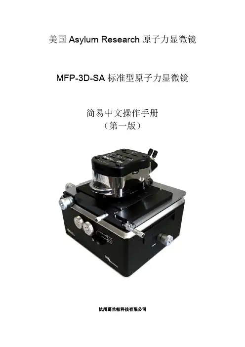

美国Asylum Research原子力显微镜MFP-3D-SA标准型原子力显微镜简易中文操作手册(第一版)杭州葛兰帕科技有限公司AC Mode in Air轻敲模式(大气)1.开启原子力显微镜控制器、电脑以及减震台。
检查各个系统是否正常启动。
2.进入WindowsXP系统,启动Igor pro软件,在Igor pro软件的下方,开启视频窗口,由原子力显微镜CCD提供光学观察窗口,为观察样品、选取下针位置以及“对光作业”提供条件。
※对光作业指的是将定位激光正确的对准到探针悬臂表面合适位置,确保力学信号反馈的准确度。
3.开启位于控制器上的激光光源及为样品提供照明用的氙灯光纤光源。
氙灯光源亮度可以根据实际需求自由设定,以可以准确观察样品以及探针为标准。
在正式进入原子力显微镜扫描过程中,可以将其关闭,以延长其灯泡使用寿命。
4.装针作业:●将探针夹持器cantilever holder按照呈三角形排布的定位小球位置卡入探针台cantilever holder stand上。
●然后用螺丝启子把cantilever holder上的螺丝松开3~4圈,不可过松,防止螺丝滑脱。
●打开探针盒,用镊子拾取探针,注意夹取探针时的角度,要保住垂直夹取,夹取探针的位置也要中间偏前段一点,为将探针尾部推入螺丝夹具口提供足够操作空间。
●探针插入夹具口后,根据实际情况,再精细调整位置,使其大致处于正中间位置。
最后用大拇指和中指夹住螺丝刀,进行旋紧。
使用两个手指的目的,就是确保力量不要太大,防止夹碎探针或者把螺丝螺纹破坏。
●拧紧的原则是感觉有阻力后再拧1/4圈,(要视具体情况定)再用镊子轻轻触碰探针侧面,看其是否因为没有夹紧而发生移动。
●装入朝上放置的扫描器头部圆形槽口,注意定位小球的位置。
5.样品台准备工作●拿起MFP-3D原子力显微镜扫描器头部。
露出原子力显微镜平板式扫描板上的样品台。
●将承载有样品的载玻片或者功能模块(功能模块具体安装另行说明)放入样品台大致正中位置。
golo 系列产品使用说明书更新日期:2014-05-27版权所有!未征得深圳市轱辘软件开发有限公司(下称“轱辘公司”)的书面同意,任何公司或个人不得以任何形式(电子、机械、影印、录制或其它形式)对本说明书进行复制和备份。
本手册专为轱辘产品的使用而设计,对于将之用于指导其它设备操作而导致的各种后果,本公司不承担任何责任。
本手册及其包含的所有范例若有更改,恕不另行通知。
因使用者个人或第三方的意外事故,滥用、误用该设备,擅自更改、修理该设备,或未按轱辘公司的操作与保养要求而致使设备损坏、遗失所产生的费用及开支等,轱辘公司及其分支机构不承担任何责任。
对于使用其它选用配件或损耗品而非轱辘公司原装产品或轱辘公司认可之产品而导致该设备损坏或出现问题,轱辘公司不承担任何责任。
正式声明:本说明书所提及之其它产品名称,目的在于说明本设备如何使用,其注册商标所有权仍属原公司。
本设备供专业技术人员或维修人员使用。
注册商标轱辘公司已在中国及海外若干国家进行了商标注册,其标志为LAUNCH。
在轱辘公司之商标、服务标志、域名、图标和公司名称还未注册之国家,轱辘公司声明其对未注册商标、服务标志、域名、图标和公司名称仍享有其所有权。
本手册所提及之其它产品及公司名称的商标仍属于原注册公司所有。
在未得到拥有人的书面同意之前,任何人不得使用轱辘公司或所提及的其它公司之商标,服务标志,域名,图标,公司名称。
您可以访问轱辘网址:了解轱辘产品信息;或写信至:中国深圳市龙岗区坂雪岗工业区五和大道北元征工业园深圳市轱辘软件开发有限公司客户服务中心收,与轱辘公司进行联系,征得其手册使用权之书面同意。
使用前须知✧此说明书适用于golo系列产品的Android与iOS版本;✧说明书内所有插图仅用作参考,具体请以软件实际显示为准;✧本仪器为精密电子仪器,使用中切勿摔碰。
✧尽量轻拿轻放,避免撞击。
✧本设备适用于12V蓄电池电压,严禁使用其它电源电压。
注:车辆维修操作并不仅局限以下注意事项,如需了解更多关于车辆诊断方面的情况,可查阅相应的车辆手册等。
米勒焊机操作说明书1-1控制按钮注:1对于所有前面板触摸开关控制钮:按下触摸开关,使灯亮,启动功能。
2铭牌上的绿标表示TIG功能,灰色表示正常的手弧焊功能。
1 编码控制钮2 电流及参数显示表3 电压表4 极性控制钮5 工艺控制钮6 输出控制钮7 脉冲控制钮8 工序控制钮9 气体/电极力控制钮10 交流波型控制钮11 电流和点焊时间控制钮12 存储按钮13 电源开关1-2 编码控制钮1-3 电流控制钮1 A 电流控制按钮2 编码控制钮3 电流表注:当脉冲功能起作用时,按下电流控制按钮,转动编码器,以设定焊接电流或峰值电流。
1-4 电流及参数显示表1-5 电压表1-6 极性控制钮1-7 工艺控制钮1-8 高频启弧和高频TIG 启动程序提升启弧:当提升启弧按钮灯亮,按下列步骤启弧,在焊接开始处把钨极触及工件,用焊枪触发开关、脚控器或手控器接通输出和保护气。
把钨极在工件上保持1-2秒,然后慢慢提升。
焊极提起后,电弧生成。
在钨极触及工件前不存在正常的开路电压,仅在钨极和工件间存在较低的感应电压,直到钨极触及工件后才激发固态输出接触器,因此钨极不会出现过热、粘条或被污染。
应用:当不允许使用高频启弧或要取代划擦启弧时。
提升启弧用于DCEN或AC TIG 工艺。
高频启弧当高频启弧按钮灯亮,按下列步骤启弧,输出接通后,打开高频帮助启弧,启弧完成后关闭高频,断弧再次帮助重新启弧。
应用:当需要非接触启弧时,高频启弧用于DCEN GTAG工艺。
1-9 输出控制钮1 输出控制按钮按下按钮,直到希望参数的LED灯亮。
标准远控---应用:与脚踏或手控电流控制器一起使用远控触发。
注:脚控或手控远控电流控制器连接后,初始电流、起始坡升、终止坡降、及终止电流由远控器控制。
如果使用开/关型触发开关,它必须是一个维持开关,所有的程序功能有效,必须由操作者设定。
远控2T保持---应用:长距离焊接时,使用远控触发保持(2T)。
如果脚控或手控电流控制器连接到底电源上,仅触发输入有效。
Guitar-pro(简称GTP,这个软件的一开始格式就是.gtp而得名)是现时网络一个非常火爆的软件,几乎每个吉他网站所提供的吉他谱都有GTP格式。
而且界面很直观地把六线谱为主要输入形式,只要你熟悉纸张的吉他谱上手GTP来说更是得心应手。
对初学者来说,只要在GTP上简单地输入谱例它就会即时为你示范演奏,可以在练习中事半功倍,的确是难得的吉他MIDI制作软件。
Guitra-pro现在已经出了5.2版,向下的还有3.0版,2.16版,2.2版。
老琴友们可能还记得一个很出色的吉他网站——吉他扒手。
可以说,GTP在国内发扬光大在一定程度上和这个网站有很大的关系!相当年,我也是吉他扒手的粉丝,可惜后来关闭了。
现在我们就对GTP5.2版从安装到设置和简单打谱作简单的介绍!GTP5.2和一般软件的安装没什么分别,首先选择安装语言,我们就选U.S.English就行了!安装完后选择Chinese(GB),OK!重启计算机!GTP就可以正常动行了!GTP5.2在下边有提供下载(附注册码)。
GTP5.2第一次运行时会自动弹出MIDI设置窗口。
这里必须要进行简单的设置,否则可能会有不发声的问题!我们在Port Device一定选择你系统的声卡,Instrument Patch选择General MIDI 把后一项打钩,设置好后按一下中间那个喇叭,如果有发出一段琴声就证明设置完成了!如果没有音乐发出把选项交替设置试试,直至成功!在这里要提醒大家,GTP播放的音乐其实就是MIDI,效果的好坏与硬件中的声卡有直接关系,GTP5.2自带出色的软波表,提升播放MIDI音乐的效果!以下是gtp下载地址本站提供下载地址:Guitarpro5.2精简版下载(11.2M)视频教学以下就对GTP的操作进行简单介绍GTP本身也自带了很多示范歌谱的。
现在你就可以用GTP将它们打开,熟悉的六线谱就会出现在你的眼前。
当然了,GTP还可以为你演奏歌谱,如上图,按下从开头演奏键,GTP马上为你演奏一份歌谱就这么简单。
INSTALLATION INSTRUCTIONSPRODUCT SAFETY & LEGAL DISCLAIMER© 2016 Go Rhino Products. All rights reserved589 W. Apollo St., Brea, CA 92821 P: 888 427 4466•IMPORTANT READ ALL INSTRUCTIONS CAREFULLY BEFORE INSTALLING, FAILURE TO DO SO MAY CAUSE PERSONAL INJURY OR DAMAGE TO PRODUCT AND/OR PROPERTY.•Review the product package and contents prior to beginning the installation. Take care when opening the packaging and removing items. If a return is needed you will want to return the product in its original packaging if possible.•This instruction guide is provided as a GENERAL installation guide, some vehicles vary dimensionally and may require additional steps.•Test fit the product on the vehicle prior to any third party modifications and or finishing. Themanufacturer and/or distributors do not accept responsibility for third party charges, labor and or third part replacement modifications. Some modifications may void the factory warranty.•Exercise due-diligence when installing this product. The manufacturer and distributors of this product do not accept any responsibility for vehicle damage or personal injury resulting from the installation of this product. Careless installation and operation can result in serious injury or equipment damage.•This product is for general off-road use. All liability for installation and use rests with the owner/operator.•INSTALLER: Once installation is complete, please return this guide along with other documentation included in this product back to the consumer for future reference. The manufacturer/distributors of this product do not guarantee this particular version will be available at a later date.R E V 3 05/13/2016PART NO.●5994000T PRODUCT DESCRIPTION:●OVERLAND OVERHEAD RACKAPPLICATION: ●JEEP WRANGLER JK UNLIMITEDINSTALLATION INSTRUCTIONS INJURY HAZARDPlease complete a shop and tool inspection prior to beginning the installation.•Always make sure you have a clean, dry and well lit work area.•Always remove jewelry, loose fitting clothing and wear protective gloves and eye protection.•Always use extreme caution when jacking or raising a vehicle for work. Set the emergency brake and use tire/wheel blocks and jack stands. Refer to the vehicle manufacturer hand book. Utilize the vehicle manufacturers designated lifting points.•Always use appropriate and adequate care in lifting parts during disassembly and installation. Seek help in lifting heavy or large items into place. Utilize jacks and or lifting devices when available.•Always insure products are secure during disassembly and installation.•Always wear eye protection and take steps to protect any exposed skin during the installations. Drilling, cutting and grinding plastic and metal may create flying particles that can cause injury.•Always use extreme caution when drilling, cutting and or grinding on a vehicle. Thoroughly inspect the area to be drilled, on both sides of material, prior to modification and relocate any objects that may become damaged.•Always assemble and tighten all fasteners per the installation instructions.•Always route electrical cables carefully. Avoid moving parts, parts that may become hot and rough or sharp edges.•Always insulate and protect all exposed wiring and electrical connections.MAINTENANCE AND CARE•Always perform regular inspections and maintenance on mounts and related fasteners.•Periodically check and tighten all fasteners.•Stripped, fractured, or bent fasteners must be replaced.•After washing the vehicle make sure to fully dry all surfaces.•In areas with cold temperatures make sure to wash the product often to remove harmful materials used on road ways.•Never use abrasive cleaners or polish compounds. Clean with a gentle soap and water. If you use wax use a non-abrasive automotive wax such as pure carnauba wax.WARNINGSome products have been designed to work together with factory rear sensor systems, factory forward facing sensor systems and factory air bags.•Installation of some of these products may alter the factory sensor system performance.•Factory sensors may read shackles or hooks protruding from the fairlead and or tow hooks.•All sensor testing is completed by Go Rhino Products and or third party testing labs on modified vehicles.•Sensor sensitivity, factory sensor housing, orientation, and operating conditions are all variables that will influence functionality of the sensors.•Installation of some product may effect the factory air bag systems.•Some products allow the use of third party products such as winches, shackles, hooks, etc. Follow the respective manufacturers operating instructions for use with our products.•Make sure to fully understand the product, it’s intended use and operation prior to use.INSTALLATION INSTRUCTIONSIf you need installation service for your new product, call the authorized distributor from whom you purchased the product or an authorized installation service company which can be found by calling toll free 1-888-427-446621/2 HourTOOLS NEEDED FOR INSTALLATION:•1/2”, 9/16” Socket & Wrench, Ratchet & Ratchet Extension •Phillips Screw Driver•5/32” & 3/16” Hex Key •Drill Motor, 3/8” & ½” Drill BitESTIMATED TIME FOR INSTALLATION:PARTS INCLUDED IN THIS LIST:Go Rhino recommends you, the installer, read this installation instruction manual from front to back before installing the product. You may also click here to view an installation video or visit /Installation-Videos.ITEM QTY.DESCRIPTION ITEM QTY.DESCRIPTIONITEM QTY.DESCRIPTION115¼” x 3/4" Button Head Hex Drive Screw (SS)9165/16” x 1” Hex Head Bolt (SS)1783/8” Flat Washer (SS)21¼” 1 1/4" Button Head Hex Drive Screw (SS)10165/16” Lock Washer (SS)1823/8” x 1” Hex Head Bolt 341/4" X 1 1/2" Hex Head Bolt (SS)11185/16” Flat Washer (SS)1923/8” Lock Washer 412¼” Lock Washer (SS)1225/16” Nylon Lock Nut (SS)2043/8” Flat Washer 512¼” Flat Washer (SS)1323/8" X 1" Button Head Hex Drive Screw (SS)2123/8” Hex Nut68¼” Flat Washer (Plastic)1443/8” x 1 ½” Hex Head Bolt (SS)2223/8” Locking Pin with Squared Wire Retainer74Adhesive Backed Rubber Washer 1523/8” x 2 ¾” Shoulder Bolt 238Polyurethane Bushing 81Spacer, 1/2" OD, 7/16" Long 1663/8” Lock Washer (SS)244Bushing Sleeve(SS)Stainless SteelINSTALLATION INSTRUCTIONS PARTS INCLUDED IN THIS LIST:ITEM QTY.DESCRIPTION ITEM QTY.DESCRIPTION25 1 Front Bracket (Driver)318Cross Bar Gasket261Front Tube (Driver)321Rear Post (Driver) 274Plastic Cap331Front Bracket (Passenger) 282Roof Rail341Front Tube (Passenger) 298Cross Bar351Rear Post (Passenger) 304Thread PlateINSTALLATION INSTRUCTIONS PARTS INCLUDED IN THIS LIST:ITEM QTY.DESCRIPTION ITEM QTY.DESCRIPTION361Tail Light Cover (Driver)421Tail Light Cover (Passenger)371Rear Bracket (Driver)431Rear Bracket (Passenger)381Rear Bracket Gasket (Driver)441Rear Bracket Gasket (Passenger)391Lower Support Bracket-B(Driver)451Lower Support Bracket-A(Passenger) 401Lower Support Bracket-A(Driver)461Lower Support Bracket-B(Passenger) 411Upper Support Bracket (Driver)471Upper Support Bracket (Passenger)36373839404146 4243444547Reference the installation instruction included with the WLF Windshield Light frame, and complete the installation of the WLF Windshield Light frame.Driver RearStep-1Remove the (2) Phillip’s screws securing OEM taillight to the vehicle, disconnect taillight wiring from the vehicle wiring harness and remove the taillight from vehicle.Step-2Position the driver side rear bracket on the body panel area where the OEM taillight wasremoved. Align and level the rear bracket and use the (4) mounting holes in the bracket as a guide and mark the location of each hole on the body panel, (FIGURE 1).Step-3Set the driver side rear bracket aside and drill 3/8” holes through the body panel at the (4) marked locations. Note: The lower right body panel area has an interior panel, drill a 3/8” hole through both the outer and inner body panel.Step-4Re-drill only the lower right hole on the outer body panel to 1/2” as a spacer tube will be installed at this location.Step-5Apply the supplied gasket to the back of the driver side bracket, (FIGURE 2).Use the (4) mounting holes in the bracket as a guide and mark the location of each hole on the body panel. Drill 3/8” holes through the body panel at the (4) marked locations.Note:The lower right body panel area has an interior panel, drill a 3/8” hole through both the outer and interior body panel, then re-drill only the lower right hole on the outer body panel to 1/2”FIGURE 1FIGURE 2INSTALLATION INSTRUCTIONS373738Driver RearStep-6Attach the lower right hole in the driver side rear bracket to the body panel using (1) ¼” x 1 1/4” button head hex drive screw, (1) ¼” plastic flat washer, (1) spacer tube and lower support bracket-B, (FIGURE 3 & 4).Step-7Attach the two upper holes in the driver side rear bracket to the body panel using (2) ¼” x 3/4” button head hex drive screws, (2) ¼” plastic flat washers and the upper support bracket, (FIGURE 3 & 4)Step-8Attach the lower left hole in the driver side rear bracket to the body panel using (1) ¼” x 3/4” button head hex drive screw, (1) ¼” plastic flat washer and lower support bracket-A, (FIGURE 3 & 4).Step-9Attach the lower support brackets to the body structure using (1) 3/8” x 1” hex bolt, (2) 3/8” flat washers (1) 3/8” lock washer and (1) 3/8” hex nut, (FIGURE 4).View from inside1-62-6-84118-19 20-2139 40View from outsideFIGURE 3 FIGURE 4Passenger RearStep-10Remove the (2) Phillip’s screws securing OEM taillight to the vehicle, disconnect taillight wiring from the vehicle wiring harness and remove the taillight from vehicle.Step-11Position the passenger side rear bracket on the body panel area where the OEM taillight was removed. Align and level the rear bracket and use the (4) mounting holes in the bracket as a guide and mark the location of each hole on the body panel, (FIGURE 5).Step-12Set the passenger side rear bracket aside and drill 3/8” holes through the body panel at the (4) marked locations.Step-13Apply the supplied gasket to the back of the passenger side bracket, (FIGURE 6).Use the (4) mounting holes in the bracket as a guide and mark the location of each hole on the body panel. Drill 3/8” holes through the body panel at the (4) marked locations.FIGURE 5FIGURE 6INSTALLATION INSTRUCTIONS434344Passenger RearStep-14Attach the lower left hole inthe passenger side rear bracket tothe body panel using (1) ¼” x 3/4”button head hex drive screw, (1) ¼”plastic flat washer, and lowersupport bracket-C, (FIGURE 7 & 8).Step-15 Attach the two upper holesin the driver side rear bracket to thebody panel using (2) ¼” x 3/4”button head hex drive screws, (2) ¼”plastic flat washers and thepassenger side upper bracket,(FIGURE 7 & 8).Step-16Attach the lower right holein the driver side rear bracket to thebody panel using (1) ¼” x 3/4”button head hex drive screw, (1) ¼”plastic flat washer and lowersupport bracket-D, (FIGURE 7 & 8).Step-17Attach the support bracketsto the body structure using (1) 3/8”x 1” hex bolt, (2) 3/8” flat washers(1) 3/8” lock washer and (1) 3/8”hex nut, (FIGURE 8).View from inside18-19 20-214647View from outsideFIGURE 7FIGURE 81-64345INSTALLATION INSTRUCTIONSStep-18Align the holes and attach the passenger side front tube and (1) plastic cap to one of the rails using (1) ¼” x 1 1/2” hex bolt (1) 1/4” lock washer and (1) 1/4” flat washer, and (1) 3/8” x 1 1/2” hex bolt (1) 3/8” lock washer and (1) 3/8” flat washer, (FIGURE 19).Step-19Align the holes and attach the passenger side rear post and (1) plastic cap to opposite end of the rail using (1) ¼” x 1 1/2” hex bolt (1) 1/4” lock washer and (1) 1/4” flat washer, and (1) 3/8” x 1 1/2” hex bolt (1) 3/8” lock washer and (1) 3/8” flat washer, (FIGURE 10). Repeat the assembly for the driver side front tube, rear post and remaining rail.INSTALLATION INSTRUCTIONS3-4-514-16 17273428273-4-52835FIGURE 10FIGURE 914-16 17INSTALLATION INSTRUCTIONSStep-20Remove the paper backing, align and apply a rubber gasket to each end of the (4) cross bars, (FIGURE 11).Step-21 Position (1) thread-plate inside the rail of the passenger side front tube, rail and rear post assembly, and attach (1) cross bar to the rail using the thread plate, (2) 5/16” x 1” hex bolts (2) 5/16” lock washers and (2) 5/16” flat washers, (FIGURE 12).Step-22 Space the (3) remaining cross bars equally along the passenger side rail assembly and repeat step-21 to attach the cross bars to the rail, (FIGURE 13).Step-23With assistance attach the rail of the driver side front tube, rail and rear post assembly to the cross bars using the thread-plates, 5/16” x 1” hex bolts, 5/16” lock washers and 5/16” flat washers.FIGURE 11FIGURE 12FIGURE 13312930289-10 119-10 1129INSTALLATION INSTRUCTIONSStep-24Attach the passenger side front bracket to the top surface of the WLF light plate using (2) ¼” x ¾” button head hex drive screws, (2) ¼” lock washers and (2) ¼” flat washers, and to the inside surface of the WLF light frame using (1) 3/8” x 1” button head hex drive screw, (1) 3/8” lock washer and (1) 3/8” flat washer, (FIGURE 14). Leave the screws loose for final adjustment. Repeat for the driver side front bracket.13-16171-4 533WLF light plate WLF light frameFIGURE 14Step-25Assemble (2) bushings and (1) sleeve in the stub tube of each front tube and each end post, (FIGURE-15).INSTALLATION INSTRUCTIONS23 35243423FIGURE 15Stub TubeStep-26With assistance position the cargo rack assemble over the top of the vehicle then position the bushings in each rear support between the two tabs on each rear bracket. Align the bushing sleeve with the hole in the tabs and secure the rear supports to the rear bracket tabs using (1) 3/8” shoulder bolt, (1) 3/8” flat washer, (1) 5/16” flat washer and (1) 5/16” nylon lock nut, (FIGURE-16). Leave the shoulder bolts and nuts loose for final adjustment.INSTALLATION INSTRUCTIONSFIGURE 16Step-27 Position the bushings in each front tube between the two tabs on each front bracket. Align the bushing sleeve with the hole in the tabs and secure the front tubes to the front bracket tabs using a 3/8” locking pin with squared wire retainer, (FIGURE-17).Step-28Tighten all fasteners securing the cargo rack assembly, and components to the vehicle.FIGURE 1715-1711-122232372625INSTALLATION INSTRUCTIONSStep-29Re-connect the wiring to thevehicle wiring harness and re-install theOEM taillights using the Phillips screwsremoved in step-1Step-30Remove the paper backing, alignand apply a rubber washer around eachthreaded hole on the driver side rearbracket, (FIGURE 18). Repeat for thepassenger side.Step-31Align and attach the driver side tail light cover to the light bracket using (2) ¼” x ¾” button head hex drive screws, ¼” lock washers and ¼” flat washers, (FIGURE 19). Tighten the screws. Repeat for the passenger side.FIGURE 19FIGURE 18 71-453736INSTALLATION INSTRUCTIONS Remember to periodically check and retighten all OEM and supplied hardware.Go Rhino warrants to Buyer that for a period of five (5) years from the date of shipment of the product(s) (“Warranty Period”) for black finishes and chrome finishes, that such products will materially conform to the specifications set forth in Go Rhino’s specifications in effect as of the date of shipment(s) and will be free from material defects in material workmanship.Go Rhino warrants to Buyer that for the life of the product(s) from the date of shipment of the product(s) (“Warranty Period”) for polished stainless steel finished products purchased after April 2004, that such products will materially conform to the specifications set forth in Go Rhino’s specifications in effect as of the date of shipments and will be free from material defects in materi al workmanship. Warranty claims must be accompanied with the original invoice and photos of the product. It is the customer’s responsibility to clean regularly and protect finish with regular applications of a nonabrasive polish that is compatible with the product’s finish.This warranty covers the cost of the product only and does not include the cost of removal, installation, third party modifications or shipping of the product. In no event shall Go Rhino be liable to buyer or any third party for any damage or harm caused by the product or use thereof, regardless of weather such damages were foreseeable and whether or not Go Rhino has been advised of the possibility of such damages, not withstanding the failure of any agreed or other remedy of its essential purpose. This warranty is void if the product shows signs of alteration, misuse, mishandling, improper care, neglect, improper application and/or damage due to improper installation. With respect to any such product(s) during the limited warranty period, Go Rhino shall, in its sole discretion, either: (i) provide a one-time repair or replacement of such products (or the defective part) or (ii) credit or refund the price of such products at the pro rata contract rate provided that, if Go Rhino so requests, Buyer shall, at Go Rhino’s expense, return such product(s) to Go R hino. The remedies shall be the Buyer’s sole and exclusive remedy and Go Rhino’s entire liability for any breach of the limited warrant (ies).Go Rhino disclaims all other warranties except to the extent that any such warranty cannot be validly disclaimed under applicable law.Finish Limited Warranty:Limited lifetime on stainless steel products (after April 2004)5 year warranty on black powder coat products5 year warranty on chrome productsThis warranty does not cover exposed weldsFinish warranty covers peeling, flaking, or cracking. Washing all finishes regularly with car wash soap and rinsing well with water is the best method for maintaining the finish on your products. You must also protect the finish with nonabrasive automotive wax on a regular basis. The use of any compound which contains abrasives becomes a self-defeating exercise as the compound scratches the finish and opens it to corrosion. The use of harsh chemicals used to remove bugs and tar may also cause the finish to fail and should be avoided.If you are unsatisfied with your purchase please contact the establishment you purchased the product from.If you need to place a warranty claim or need assistance, the Go Rhino customer service team will answer any questions you may have. Please contact the Go Rhino customer service team at 1-888-427-4466 during normal business hours Monday thru Friday 7 am to 5 pm PST. You may also email ********************. In order to better serve you please provide a copy of the original invoice / receipt, a photo of the issue you are experiencing and a photo of the vehicle the product is installed on. All warranty returns must have an approved RGA number. The RGA number must be clearly marked on the exterior of the return package. All approved warranty returns must be shipped to Go Rhino Products, 1002 Carriers Drive, Laredo, Texas 78045.INSTALLATION INSTRUCTIONSLIMITED WARRANTYPRODUCT REGISTRATIONPlease remember to register your new purchase. You may register your product at . Registering your product may help speed any future warranty or customer service inquiries. Thank you again for purchasing from Go Rhino Products Please take a few minutes to view additional products for your vehicle and more at These installation instructions are available on the Go Rhino web site along with installation videos formany of our products. 。