BOSSMICROBR-80中文使用说明书
- 格式:docx
- 大小:17.81 KB
- 文档页数:6
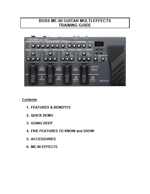
BOSS ME-80 GUITAR MULTI-EFFECTSTRAINING GUIDEContents1. FEATURES & BENEFITS2. QUICK DEMO3. GOING DEEP4. FIVE FEATURES TO KNOW and SHOW5. ACCESSORIES6. ME-80 EFFECTS1. FEATURES & BENEFITS•Traditional BOSS ME-type simple knob-based operation•COSM amp and effect modeling•USB port and downloadable BOSS Tone Studio® editor for computer recording, onscreen editing, patch download, forMIDI control, using the ME-80 as an audio interface, etc.•New dual pedals provide easy access to all functions in real time, including Bank Up/Down, Manual Mode on/off, etc.•9 Effect groups: Preamp, Comp/FX1, OD/DS, Modulation, Delay, EQ/FX2, Reverb, Pedal FX, NS•9 COSM amplifier models, 11 COSM OD/DS models, 11 Comp/FX1 effects plus additional EQ/ FX2 effects•Includes 2 MDP effects: MO-2 Overtone and TE-2 Tera Echo•10 PEDAL FX types, including +2 Octave, Freeze, OD/DS control, and more•Built in 38-second Phrase Looper w/ unlimited overdubs•Modulation and Delay effects support tap tempo for real time tempo-synched effects•New CONTROL pedal can select multiple effects or change parameters•Built-in chromatic tuner w/ mute for silent tuning•Runs on batteries (included) or optional BOSS PSA-120S AC adaptor2. QUICK DEMOThe Quick Demo is a way to get a customer interested in a product in less than 60 seconds.Before You Start1. Connect the MONO (L) Gt. AMP output of the ME-80 to the clean channelof a good amp, such as a Roland JC-120 or other pro quality amp.NOTE: It is very important to use a pro-quality guitar amp. Why run a high-end effect through a low-end amp?2. Set the amp’s tone controls for a flat response.3. Connect the ME-80 to power using a BOSS PSA-120S AC Adaptor.4. Plug a guitar into the GUITAR INPUT of the ME-80.5. Press the MEMORY/MANUAL pedal to select MANUAL. The green LEDwill light indicating MANUAL Mode.6. Use the other pedals to turn all ME-80 effects off.ABOUT MANUAL MODEManual mode allows a multi-effect such as the ME-80 to operate much like simple stomp boxes. Rather than changing pre-programmed sounds, when you step on a pedal in manual mode you are tuning on or off a particular effect, just as if it were a single stomp box in a pedalboard. On the ME-80, there are eight pedal switchable effects: Comp, OD/DS, Mod, Delay, COSM Amp, EQ, Rev, and Expression Pedal FX. Any or all of these can be on at the same time just by pressing the corresponding pedal.ABOUT MEMORY MODEIn Memory Mode, pressing a number pedal selects an entire preset or user made patch.THE QUICK DEMO: USING THE ME-80 IN MANUAL MODEThis Quick Demo has five steps. You can do some or all of the steps. STEP ONE: Add Distortion1. Make sure that all the effects are off; then play the guitar through the ME-80 to show the dry sound.2. Select a DISTORTION or OVERDRIVE type by turning theOVERDRIVE/DISTORTION TYPE KNOB.3. Set the OD/DS control knobs to an appropriate setting.(Not suggested settings. For illustration only)4. Press the OD/DS PEDAL to turn on the Overdrive. The red LED will light.5. Play some chords or leads.STEP TWO: Add Modulation1. Turn the MODULATION TYPE knob to select a Modulation effect. Do notuse Harmonist or Octave.2. Set the MODULATION Controls knobs to an appropriate setting.(Not suggested settings. For illustration only)3. Press the MOD PEDAL to turn on the Modulation effect. The red LED willlight.4. Play some chords or leads.STEP THREE: Add Delay1. Turn the DELAY TYPE knob to select ANALOG.2. Set the DELAY Control knobs to an appropriate setting.(Not suggested settings. For illustration only)3. Press the DELAY PEDAL. The red LED will light.4. Play some chords or leads.5. Hold the DELAY PEDAL down for two seconds.6. Tap in a different delay time with the DELAY PEDAL.NOTE: You can also change the rate of the Modulation effect by repeating this procedure with the MOD PEDAL.STEP FOUR: Add PEDAL FX1. Turn the PEDAL FX knob to select WAH.2. Press the toe end of the EXPRESSION PEDAL hard to turn on the WAH.The PEDAL FX LED will light.3. Play some chords or leads using the WAH.STEP FIVE: Show the Phrase LooperNOTE: When using the Phrase Looper, use the DELAY PEDAL to control all recording, playback, and overdub functions.1. Set the DELAY TYPE knob to PHRASE LOOP. The red LED will flash at asteady rate.2. Use the NUMBERED (FX) PEDALS to turn on/off effects needed for aclean sound.3. When you are ready to record, press the DELAY PEDAL. Recording willstart. The red LED will flash quickly.4. When you’re finished with the first loop recording, press the DELAYPEDAL. The Phrase will play back. The LED will light without flashing.NOTE: Make sure you do this on the beat.5. Change the guitar’s tone using the NUMBERED PEDALS.6. Press the DELAY PEDAL again to overdub another track onto the existingloop.7. If desired, repeat steps 4-6.8. When you are finished, press the DELAY PEDAL twice quickly to stop thelooper.NOTES:The ME-80’s Memory Mode has two sets of patch Banks: Preset (P) and User (U). Each has nine Banks: 1-9, with four patches in each. The display indicates whether you are in the Preset or User Bank set and which Bank is selected.This indicates Userbank 1How to Switch to Memory Mode1. From MANUAL Mode, press the MEMORY/MANUAL pedal to selectMEMORY. The red MEMORY LED will light indicating MEMORY Mode. How to Change Programs in Memory Mode1. IN MEMORY Mode, press the BANK UP or DOWN pedal to changebanks.2. Press PEDAL ONE, TWO, THREE or FOUR to select a patch within theBANK.How to Edit a Patch1. Use the above procedures to select a patch in a USER BANK.2. Press EDIT.3. Adjust the settings of the knobs and pedals.NOTE: you may have to move the knobs past their current stored settings to enable the new settings.4. Press WRITE.5. If necessary, press the BANK UP/DOWN pedals and NUMBER pedals toselect the patch number for the new patch.6. Press WRITE again to save the sound in the selected patch location. How to Use the Tuner1. Hold down the MEMORY/MANUAL pedal for at least two seconds..2. Tune up. The note played will show in the Display. The LED’s in thedisplay will indicate whether the note is sharp, flat, or in tune.3. Press any NUMBER pedal or press EXIT to exit the tuner.How to Use with a Computer via USBThe ME-80 has an on-screen Editor (a free download from the BOSS or Roland website) for editing your ME-80 sounds on a computer. You can also download alternate patches and load them into the ME-80 via USB and use the ME-80 as a USB-audio interface for computer recording. It can even respond to MIDI program and control changes via USB.1. Download and install the ME-80 software from the Roland website.2. Select MANUAL Mode.3. Press EDIT until you get to SYSTEM SETTINGS USB parameters.4. Use the BANK UP/DOWN pedal to set the value of the parameters.5. Press WRITE to save the settings.How to Re-Initialize the ME-801. Set the ME-80 to Manual Mode.2. While holding down EDIT, press the MOD PEDAL. “FR” (factory reset)will appear in the display.3. Press WRITE. The TUNING GUIDE LED will flash.4. Press WRITE again. The display will flash and the ME-80 will be reset.4. FIVE THINGS TO KNOW and SHOW1. Easiest to use BOSS multi-effect. Just turn the knobs!2. COSM modeled Amps, OD/DS, Modulations, and Delays3. USB for computer recording, on-screen editing, patch downloading andbackup4. Tap tempo both Mod and Delay5. New dual pedal OS allows more flexibility and ease of use.5. ACCESSORIES1. BOSS PSA-120 AC Adapter2. BOSS Bag-S2 Carrying bag3. Roland RH-5, RH-200 or other headphones4. Instrument cables6. ME-80 EFFECTSPREAMP ORIGINAL1. AC Original amp good for acoustic guitars w/PUs2. CLEAN Original clean amp with uncolored tone response3. TWEED Fender Bassman 4x10⁴. CRUNCH BOSS GT-100 Advanced crunch amp5. COMBO Vox AC-30TB6. LEAD Mesa Boogie Mk series lead channel7. DRIVE GT-100 Advanced drive amp8. STACK Marshall Plexi channel 19. METAL Bogner UberschallCOMP/FX11. COMPRESSOR2. T-WAH UP3. T-WAH DOWN4. OCTAVE5. SLOW GEAR6. DEFRETER7. Single>Hum (Pickup Simulator)8. Hum>Single (Pickup Simulator)9. SOLOCOSM OVERDRIVE/DISTORTION1. BOOST BOSS FB-22. OVERDRIVE BOSS OD-13. T-SCREAM Ibanez TS-8084. BLUES BOSS BD-25. TURBO OD BOSS OD-2 w/ TURBO on6. DISTORTION BOSS DS-17. TURBO DS BOSS DS-2 w/ TURBO on8. METAL DS BOSS MT-29. CORE BOSS ML-210. FUZZ Electro-Harmonix Big Muff11. OCT FUZZ Vintage Roger Mayer OctaviaMODULATION1. PHASER2. FLANGER3. TREMOLO4. CHORUS5. VIBRATO6. PITCH SHIFT7. HARMONIST8. ROTARY9. UNI-V Univox Univibe10. DELAY11. OVERTONE BOSS MO-2 DELAY1. 1-99ms2. 100-600 ms3. 500-6000ms4. ANALOG5. TAPE6. MODULATE7. REVERSE8. CHO+DELAY9. TEMPO10. TERA ECHO11. PHRASE LOOPEQ/ FX21. PHASER2. TREMOLO3. BOOST4. DELAY5. CHORUS6. EQNS (NOISE SUPPRESSOR)REVERB1. ROOM2. HALL3. SPRINGPEDAL EFFECTS1. WAH2. VOICE3. +1 OCTAVE4. +2 OCTAVE5. –1 OCTAVE6. FREEZE7. OSC DELAY8. OD/DS9. MOD RATE10. DELAY LEVEL。

博士品质 博士德软件〖BOSS 博士德〗 商务管理系列软件操 作 手 册石家庄博士德软件科技开发有限公司方圆电子音像出版社出版压回路交叉资料试卷技高中资料试序言尊敬的用户,感谢您选用博士德系列软件!为了您在今后的操作中更顺畅,请您抽出一点宝贵的时间,仔细阅读本书的内容,相信会对您有所帮助。
本软件共分七个模块,分别为:配置帐套、系统维护、商品管理、往来帐管理、合同管理、客户信息及经理查询。
它们分别与本操作手册的第二部分配置帐套和系统维护、第三部分商品管理、第四部分往来帐管理、第五部分客户信息和第六部分经理查询相对应。
安装本软件之前,请仔细核对您的硬件、软件和软件环境是否符合本系统的运行要求,必要时请进行相应的调整。
安装过程可以由您自行安装,也可以请有经验的软件技术人员协助进行安装。
安装后,首先要进行初始化工作。
首次使用本系统的用户,请认真阅读第一章:系统安装、第三章:系统初始化。
本操作手册与软件中的联机帮助在内容上基本上一致。
您可以放心使用博士德软件,我们将为您提供安全的保障。
目录第一部分系统安装及初始化第一章系统的安装 (6)第二章计算机系统的相关设置 (10)第一节 win98系统的设置 (10)第二节打印机的安装与设置 (12)第三章系统的初始化 (15)第一节建立新帐套 (15)第二节操作员维护及其权限的设置 (15)第三节基本数据录入 (17)第四节期初数据验收 (21)第二部分配置帐套及系统维护第四章配置帐套 (24)第五章系统维护 (31)第一节维护系统 (32)第二节维护数据 (33)第三节操作员维护及其权限的设置 (38)第三部分商品管理第六章业务流程综述和数据维护 (39)第一节业务流程综述 (39)第二节菜单命令 (40)第三节计算机什么时候处理数据 (48)第七章进货管理 (50)第一节单据的录入 (50)第二节单据的查询 (59)第八章库存管理 (64)第一节库存商品、盘点单、内部调拨单的查询 (64)第二节盘点单、内部调拨单的建立与编辑(修改) (66)第三节货位维护 (69)第九章销售管理 (71)第一节清单的建立、编辑和修改 (71)第二节清单的查询 (74)第十章往来帐务 (75)第一节应收/应付帐款管理 (75)第二节应收/应付帐款发生录入 (76)第三节应收/应付帐款收回/支付录入 (77)第十一章统计分析 (79)第一节日统计与营业日报表 (79)第二节月统计与营业月报表 (81)第三节年统计与营业年报表 (82)第四节按结算方式统计收款情况 (83)第四部分合同管理第十二章合同管理 (84)第五部分客户信息管理第十三章客户信息 (87)第一节客户信息管理 (87)第二节打印输出 (90)第三节传真 (92)第六部分经理查询及菜单命令第十四章经理决策查询管理 (94)第一节商品查询 (94)第二节查询库存信息 (96)第三节查询客户信息 (99)第四节查询供应商信息 (100)第五节往来帐项查询 (100)第六节业务员业绩考核 (101)第七节经营情况分析和家底查询 (102)第十五章费用控制 (104)第十六章快捷键速查和通用模块 (106)第一节快捷键速查 (106)第二节通用模块及操作方法 (106)第一部分系统安装及初始化第一章系统的安装目前,博士德系列软件的各种版本都是以windows95 / Windows98 / WinNt / Windows2000为工作平台的,所以在安装系统前必须先安装windows操作系统,关于windows的安装请用户参阅其他相关的手册,本手册假定用户已经安装了windows 操作系统。

MICRO BR BR-80Digital Recorder▼▼▼▼▼▼▼▼The Complete Studio To GoDon’t be fooled by its size — this little studio is loaded! The MTR (Multi-Track Recorder) mode offers 64 V-Tracks with eight simultaneous playback tracks. In addition, a dedicated stereo rhythm track is provided, as well as an onboard library of great grooves to choose from. The intuitive user-interface continues the simple-to-use tradition of BOSS’ acclaimed BR series, with a graphical design that follows the layout of a conventional recording console. With EQ, reverb, and mastering tools plus, world-class COSM amps and effects for guitar, bass, and vocals the BR-80 is ready to deliver complete, pro-quality recordings with ease.High-Quality Multi FXThe BR-80 is packed with professional multi-effects powered by a newly developed custom DSP chip. Over 40 types of COSM amp models give you instant access to a wide range of powerful guitar and bass sounds. The preset patches allow fi rst-timers and pros alike to enjoy high-quality sounds immediately, while power users can tweak parameters in micro detail for the ultimate tonal control. The dedicated vocal effects, comparable with BOSS’s popular VE-20, include doubling, harmony effects, pitch correction, and more.Virtual Jam BandThe BR-80’s eBand mode offers musicians a fun way to play along with their favorite songs. With the bundled eBand Song List Editor software, you can import CD, MP3, and WAV audio fi les from a computer via USB. The Center Cancel function can be used tominimize the volume of pre-recorded vocals and solos for play- and sing-along enjoyment. eBand mode is also an excellent partner for musical training, as it lets you record your performance adjustplayback speed and/or pitch as desired.PC CompanionThe ultra-fl exible BR-80 can be used as a stand-alone digital recorder or as audio interface for a USB-equipped computer. Cakewalk’s SONAR X1 LE DAW software (for Windows) is bundled with the BR-80, giving users a full-fl edged PC-based music production environment with latency-free recording and a powerful range of COSM amps and effects. Furthermore, the bundled Wave Converter software lets you easily exchange data between the BR-80 and SONAR X1 LE or any other DAW.Built-In Stereo MicIn combination with the onboard high-grade stereo condenser microphones, the BR-80’s Live Rec mode lets you capture pristine stereo recordings instantly. Record vocals, guitar parts, and song ideas the moment inspiration strikes. Your recorded audio fi les can be easily imported into the BR-80’s MTR mode to use as a basis for multi-track song production.MICRO BR BR-80 Specifications■ Tracks [ MTR Mode ] Tracks: 8, Simultaneously recording track: 2, V-Track: 64 (8 V-Tracks per each Track) [ eBand Mode ] Tracks: 2 (stereo), Simultaneously recording track: 2 (stereo) [ LIVE REC Mode ] Tracks: 2 (stereo), Simultaneously recording track: 2 * Either the playback or the recording. ■ Recording Media SDHC Memory Card: 4 GB—32 GB, SD Memory Card: 1 GB—2 GB ■ Data Type [ MTR Mode ] Linear (Bit Depth: 16 bits) [ eBand Mode ] eBand Songs (Recording/Playback), WAV (Bit Depth: 16 bits, Playback only), MP3 (Bit Rates: 64 kbps—320 kbps, Playback only) [ LIVE REC Mode ] WAV (Bit Depth: 16 bits, Recording/Playback), MP3 (Bit Rates: 64 kbps—320 kbps, Recording/Playback) ■ AD Conversion 24 bits ■ DA Conversion 24 bits ■ Sample Rate 44.1 kHz ■ Recording Time (conversion in one track) [ MTR Mode ] 1 GB: 3 hours, 32 GB: 100 hours [ eBand Mode ] (eBand Song) 1 GB: 4 hours, 32 GB: 130 hours [ eBand Mode/LIVE REC Mode ] (WAV 16-bit, stereo) 1 GB: 1.5 hours, 32 GB: 50 hours (MP3 128 kbps, stereo) 1 GB: 16 hours, 32 GB: 550 hours * The above-listed recording times are approximate. Times may be slightly shorter depending on the number of songs that were created. * The above number of the MTR mode is the total for all the tracks that are used. If each of the eight tracks contains an equal amount of data, the length of the resulting song will be approximately 1/8 of the above. ■ Nominal Input Level GUITAR/MIC IN jack: -20 dBu (GUITAR/MIC SW = GUITAR), -40 dBu (GUITAR/MIC SW = MIC), LINE IN jack: -10 dBu ■ Input Impedance GUITAR/MIC IN jack: 1 M Ω (GUITAR/MIC SW = GUITAR), 6 k Ω (GUITAR/MIC SW =MIC), LINE IN jack: 10 k Ω ■ Nominal Output Level PHONES/LINE OUT jack: -14 dBu ■ OutputImpedance PHONES/LINE OUT jack: 22 Ω ■ Display Graphic LCD 128 x 64 dots (Backlit LCD) ■ USB Functions 24-bit/44.1 kHz USB-AUDIO (Hi-Speed USB), USB Mass Storage Class (Hi-Speed USB), BUS Power operation ■ Connectors GUITAR/MIC IN jack (1/4" phone type), LINE IN jack (Stereo miniaturephone type), PHONES/LINE OUT jack (Stereo miniature phone type), USB connector (mini-B type), DC IN jack ■ Power Supply DC 9 V: AC Adaptor (sold separately), Alkaline battery (AA, LR6) x 2, Rechargeable Ni-MH battery (AA, HR6) x 2 or USB Bus Power ■ Current Draw 130 mA (DC IN) Alkaline dry cell batteries: Approximately 6 hours (with continuous playback of 8 tracks, power save function) * May vary according to usage conditions, batteries used, and type of SD card used. ■ Dimensions 138.0 (W) x 86 (D) x 21.7 (H) mm / 5-7/16 (W) x 3-7/16 (D) x 7/8 (H) inches ■ Weight 140 g / 5 oz ■ Included Accessories SD Memory Card, SONAR X1 LE DVD-ROM, USB Cable (mini-B type), Alkaline battery (AA, LR6) x 2, Owner’s Manual ■ Options AC Adaptor (PSA series), Silicone Rubber Case and Carrying Pouch: BA-BR80S* 0 dBu = 0.775 Vrms* The specifications are subject to change without notice.BA-BR80SSilicone Case/Pouch Set for BR-80This custom-made silicone case and carrying pouch is specially designed forthe MICRO BR BR-80. The case protects the unit from scratches and dust and provides a secure grip. It also reduces unwanted noise due to vibrations during operation while using the onboard mics. The carrying pouch, made of the cushioned material, protects s ■ Side Panel (Right)■ Side Panel (Left)。
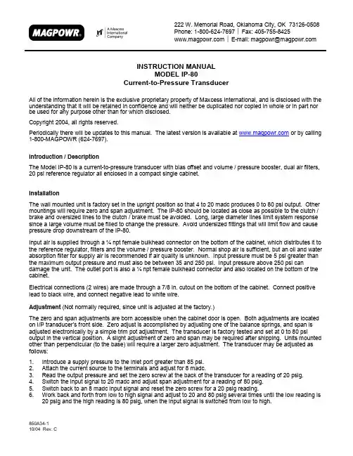
222 W. Memorial Road, Oklahoma City, OK 73126-0508Fax: 405-755-8425Phone:1-800-624-7697E-mail:*******************INSTRUCTION MANUALMODEL IP-80Current-to-Pressure TransducerAll of the information herein is the exclusive proprietary property of Maxcess International, and is disclosed with theunderstanding that it will be retained in confidence and will neither be duplicated nor copied in whole or in part norbe used for any purpose other than for which disclosed.Copyright 2004, all rights reserved.Periodically there will be updates to this manual. The latest version is available at or by calling1-800-MAGPOWR (624-7697).Introduction / DescriptionThe Model IP-80 is a current-to-pressure transducer with bias offset and volume / pressure booster, dual air filters,20 psi reference regulator all enclosed in a compact single cabinet.InstallationThe wall mounted unit is factory set in the upright position so that 4 to 20 madc produces 0 to 80 psi output. Othermountings will require zero and span adjustment. The IP-80 should be located as close as possible to the clutch /brake and oversized lines to the clutch / brake must be avoided. Long, large diameter lines limit system responsesince a large volume must be filled to change the pressure. Avoid undersized fittings that will limit flow and causepressure drop downstream of the IP-80.Input air is supplied through a ¼ npt female bulkhead connector on the bottom of the cabinet, which distributes it tothe reference regulator, filters and the volume / pressure booster. Normal shop air is sufficient, but an oil and waterabsorption filter for supply air is recommended if air quality is unknown. Input pressure must be 5 psi greater thanthe maximum output pressure and must also be between 35 and 250 psi. Input pressure above 250 psi candamage the unit. The outlet port is also a ¼ npt female bulkhead connector and also located on the bottom of thecabinet.Electrical connections (2 wires) are made through a 7/8 in. cutout on the bottom of the cabinet. Connect positivelead to black wire, and connect negative lead to white wire.Adjustment (Not normally required, since unit is adjusted at the factory.)The zero and span adjustments are born accessible when the cabinet door is open. Both adjustments are locatedon I/P transducer’s front side. Zero adjust is accomplished by adjusting one of the balance springs, and span isadjusted electronically by a simple trim pot adjustment. The transducer is factory tested and set at 0 to 80 psioutput in the vertical position. A slight adjustment of zero and span may be required after shipping. Units mountedother than perpendicular (to the base) will require a larger zero adjustment. The transducer may be adjusted asfollows:1. Introduce a supply pressure to the inlet port greater than 85 psi.2. Attach the current source to the terminals and adjust for 8 madc.3. Read the output pressure and set the zero screw at the back of the transducer for a reading of 20 psig.4. Switch the input signal to 20 madc and adjust span adjustment for a reading of 80 psig.5. Switch back to an 8 madc input signal and reset the zero screw for a 20 psig reading.6. Work back and forth from low to high signal and adjust to 20 and 80 psig several times until the low reading is20 psig and the high reading is 80 psig, when the input signal is switched from low to high.850A34-1SpecificationsOutput:Maximum supply pressure: Input:Minimum supply pressure: Flow Capacity:Exhaust Capacity:Shock and Vibration Effect on Output Pressure: Brake Pressure Gage: Filters (2):Maintenancepressure drop in the filters. RepairWiring DiagramDimensions1.16 [28 mm]。

2018-05 BSC-800型恒温恒湿箱(液晶显示)使用说明书上海博迅实业有限公司医疗设备厂SHANGHAI BOXUN INDUSTRY&COMMERCE Co.,Ltd.MEDICAL EQUIPMENT FACTORY目录告知-------------------------------------------------1安全警示标志、标识说明-------------------------------2安全操作预防措施-------------------------------------3-5产品相关(适用范围、工作原理、技术参数)-------------6产品结构---------------------------------------------7-9设备安装---------------------------------------------10-11操作方法---------------------------------------------12-13报警和安全功能---------------------------------------14日常使用、维护和保养---------------------------------15辅助配置连接-----------------------------------------16故障排除---------------------------------------------17规格配置表-------------------------------------------18接线图-----------------------------------------------19产品装箱单-------------------------------------------20告知●为保证安全使用本设备,请在使用前仔细阅读本说明书。

HIROSS恒温恒湿机房精密空调操作手册HIMOD系列北京****科技有限公司技术部2009年01月01日目录第一章HIMOD系列海洛斯空调概述 (2)型号多 (3)控制技术先进 (3)制冷系统 (3)送风系统 (3)加湿系统 (3)加热系统 (4)1.7其它 (4)第二章HIMOD系列海洛斯空调型号含义 (4)第三章有关空调的一些资料 (5)气流组织方式(详见下图) (5)盖板纽开启方式(详见下图) (5)空调重量(单位:Kg) (5)机组尺寸及维护空间 (6)第四章制冷循环管路示意图 (7)风冷却(A型) (7)水冷却(W型) (8)双冷源(D型) (9)单系统(C型) (10)双系统(C型) (10)第五章调速风机调速接线示意图 (11)第六章MICROF ACE概述 (12)概述 (12)面板简介液晶显示屏 (13)液晶显示屏介绍 (13)第七章MICROF ACE面板的操作 (13)第八章控制器的使用 (14)控制器(HIROMATIC)概述 (14)控制器的操作 (15)菜单结构 (17)第九章日常维护及特殊维护 (18)日常维护 (18)特殊维护 (19)第十章常见报警及处理 (20)低压报警 (20)高压报警 (21)加湿报警 (21)失风报警 (21)电加热过热报警 (22)显示器发黑 (22)空调不制冷 (22)附录1:参数列表 (22)附录2:报警内容列表 (26)附录3:各菜单项含义: (28)第一章HIMOD系列海洛斯空调概述HIMOD系列海洛斯空调(HIMOD空调)是当今世界上最先进的机房专用恒温恒湿机房专用精密空调。
随着IT业的突飞猛进的发展,各种布局、面积差别很大的机房如雨后春笋般纷纷出现了,使用环境也不一而同。
为适应各种不同要求的机房,新开发的海洛斯HIMOD系列空调应运而生。
她是在保留她的前一代产品HIRANGE系列机房空调的优点,又应用了当今世界上提高了的制冷技术及制冷部件制造工艺,使用当今最先进的模块化设计理念生产出来的高科技机房空调产品。

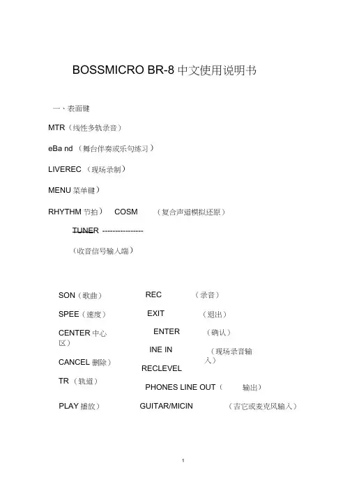
BOSSMICRO BR-8中文使用说明书一、表面键MTR(线性多轨录音)eBa nd (舞台伴奏或乐句练习)LIVEREC (现场录制)MENU菜单键)RHYTHM节拍)COSM (复合声道模拟还原)TUNER ----------------(收音信号输入端)SON(歌曲)SPEE(速度)CENTER中心区)CANCEL 删除)TR (轨道)REC (录音)EXIT (退出)ENTERINE INRECLEVEL(确认)(现场录音输入)PHONES LINE OUT(输出)PLAY播放)GUITAR/MICIN (吉它或麦克风输入)* ERASE (清除)* COPY (复制)OPTIMIZE (使XX 最优化)、MENU ;菜单)MENU(菜单)INPUTSENS 输入感觉)TRACKEDIT 编辑轨道)> MASTERING/BOUNCE 控制 /重新恢复)FUNCTION (功能设置)三、SONG 歌曲)L SELECT 选定的) ―► NEW (新的)SONG(歌曲)‘一> INFO (提出的要求)SONG (歌A.PUNCH (打击)NO CATEGORY没有类目)PUSH [ENTER] to CREATE NEW SONG 撩ENTER!仓U造新歌曲)Are you sure? (你确定吗?)[EXIT]:CANCEL (按EXIT 键取消)[ENTER]:OK (按ENTER键确定)to CREATE New SONG 去(仓作新歌曲)INPUT SENS (输入感觉)1. SENSITIVITY (敏感度)2. INPUT (输入)3. INTERNAL MIC (内部的麦克风)TRACK EDIT (编辑音轨)1. COPY (复制)一OURCE (源头)[TR1-V1 ]PEST (网络)[TR1-V1 ] PUSH [ENTER] to SET TIME (按ENTER!设置时间)2. MOUE (移动)SOURCE(源头)[TR1-V1 ]PEST (网络)[TR1-V1 ]PUSH [ENTER] to SET TIME (按ENTER!设置时间)3. ERASE (清除)SOURCE(源头)[TR1-V1 ]PUSH [ENTER] to SET TIME (按ENTER!设置时间)4. ENCHANGE(替换)SOURCE (源头1)[ TR1-V1 ]SOURCE 2源头2)[ TR1-V1 ]PUSH [ENTER] to ENCHANGE 按ENTERS 进行替换)5. WAV (声音资源文件)——IMPORT (输入) ---------------MASTERING/BOUNCE控制/重新恢复)1. BOUNCE (重新恢复)2. MASTERING (控制)FUNCTION (功能设置)1.SYSTEM (系统)LCDCONTRAST(显示屏对比度)LCDBACKLIGHT (显示屏背后照亮)POWER SAVE (功率保存)AUTOPOWER OF(F 自动功率被取消)REMAININFO (保存信息)PATCH SYNC (修补同步)BATTERY (电源选择)2.SD INFO (SD卡提出要求)TOTAL SIZE (总计大小)REMAIN SIZE (剩余大小)3.SD FORMAT (SD卡格式化)PUSH [ENTER] to FORMAT SD CAR(按ENTERS SD卡格式化)。

V I D E O B A R V B‑S请阅读并保留所有安全、安全性和使用说明。
重要安全说明有关 Bose Videobar VB‑S(包括配件和替换件)的更多信息,请参阅/VBSDownloads上的用户指南或联系 Bose 客户服务。
请保留这些说明。
请注意所有警告。
只能使用干布进行清洁。
本产品包含 ¼"–20 UNC 螺纹插件。
如果您使用该插件,应确保其连接的附件能够支撑产品重量,不会发生倾覆或掉落的危险。
有关与本产品配合使用的其他附件和配件的信息,请访问/VBSDownloads。
如果使用推车,则在移动推车/设备时应格外小心,以免因倾倒而造成伤害。
任何维修事宜均请向专业人员咨询。
如果设备有任何损坏(例如电源线或插头受损、液体溅入或物体落入设备内、设备受淋或受潮、不能正常工作或跌落),均需进行维修。
警告/小心此符号表示产品箱体内存在未绝缘的危险电压,可能会造成触电危险。
此符号表示本指南中有重要操作和维护说明。
本产品含有磁性材料。
有关这是否会影响到您的植入式医疗器械,请咨询您的医生。
包含可能导致窒息危险的小部件。
不适合 3 岁以下的儿童使用。
所有 Bose 产品的安装都必须遵守当地、州、联邦和行业规范。
安装人员有责任确保扬声器和安装系统的安装都符合适用的法规,包括当地的建筑法规和规定。
安装本产品前,请咨询拥有司法权的当地监管机构。
放置产品时,确保其不会堵塞您显示屏上的通风口。
请参阅您显示屏的用户指南,并按照制造商的说明进行安装。
未经授权切勿改装本产品。
若需要替换电池,仅可使用 AAA/LR03 碱性电池。
此产品随附的电池如果处理不当、更换不当或更换为不正确的类型,可能存在起火、爆炸或化学灼伤危险。
如果处理不当,电池可能导致着火或化学灼伤。
请勿对其进行充电、拆解、加热或焚烧。
请勿让儿童接触电池。
如果电池漏液,请避免让液体与皮肤或眼睛接触。
如果接触到了液体,请咨询医生。
请勿将含有电池的产品置于过热区域(例如避免阳光直射并远离火源等)。
BOSSMICRO BR-80中文使用说明书一、表面键MTR(线性多轨录音)eBand (舞台伴奏或乐句练习)LIVEREC (现场录制)MENU (菜单键)RHYTHM (节拍) COSM(复合声道模拟还原)TUNER(收音信号输入端)SONG(歌曲) REC(录音)SPEED(速度) EXIT(退出)CENTER(中心区) ENTER(确认)CANCEL(删除) INE IN(现场录音输入)TR(轨道) RECLEVEL(录制电平)STOP(停止) PHONES LINE OUT(输出)PLAY(播放) GUITAR/MICIN(吉它或麦克风输入)二、MENU(菜单)三、SONG(歌曲)NO CATEGORY (没有类目)PUSH [ENTER] to CREATE NEW SONG (按ENTER健创造新歌曲) Are you sure? (你确定吗?)[EXIT]:CANCEL (按EXIT 键取消)[ENTER]:OK (按ENTER 键确定)to CREATE New SONG (去创作新歌曲)INPUT SENS (输入感觉)1.SENSITIVITY (敏感度)2.INPUT (输入)3.INTERNAL MIC (内部的麦克风)TRACK EDIT (编辑音轨)1.COPY (复制) SOURCE (源头)[ TR1-V1 ] PEST (网络) [ TR1-V1 ] PUSH [ENTER] to SET TIME (按ENTER键设置时间)2.MOUE (移动)SOURCE (源头)[ TR1-V1 ]PEST (网络) [ TR1-V1 ]PUSH [ENTER] to SET TIME (按ENTER键设置时间) 3.ERASE (清除)SOURCE (源头)[ TR1-V1 ]PUSH [ENTER] to SET TIME (按ENTER键设置时间) 4.ENCHANGE (替换)SOURCE 1(源头1)[ TR1-V1 ]SOURCE 2(源头2)[ TR1-V1 ]PUSH [ENTER] to ENCHANGE (按ENTER键进行替换) 5.WAVIMPORT (输入)MASTERING/BOUNCE (控制/重新恢复)1.BOUNCE (重新恢复)2.MASTERING (控制)FUNCTION (功能设置)1.SYSTEM (系统)LCDCONTRAST (显示屏对比度)LCDBACKLIGHT (显示屏背后照亮)POWER SAVE (功率保存)AUTOPOWER OFF (自动功率被取消)REMAININFO (保存信息)PATCH SYNC (修补同步)BATTERY (电源选择)2.SD INFO (SD卡提出要求)TOTAL SIZE (总计大小)REMAIN SIZE (剩余大小)3.SD FORMAT (SD卡格式化)PUSH [ENTER] to FORMAT SD CARD (按ENTER键SD卡格式化)。
BOSS BR-800 DIGITAL RECORDERTRAINING GUIDEContents1. FEATURES2. QUICK DEMO3. EZ RECORDING4. SONG SKETCH5. EFFECTS6. RHYTHM7. SIX THINGS TO KNOW and SHOW8. ACCESSORIES1. FEATURES∙4-track simultaneous recording, 8-track simultaneous playback plus dedicated stereo rhythm track playback∙EZ Recording interactively guides through the recording process∙Powerful guitar, bass, and vocal effects derived from BOSS’s flagship processors∙Song Sketch recording for quick stereo capture in WAV format∙Built-in advanced drum machine with editor software∙Functions as a USB audio interface and DAW control surface∙Cakewalk SONAR 8.5 LE software with full audio loops and backing tracks included∙Built-in stereo condenser microphone for instant recording∙Sleek new interface based on touch sensors∙1GB SD included (supports up to 32GB SDHC card)∙Runs on six AA batteries/USB bus power/AC adaptor (included)2. QUICK DEMOThe Quick Demo is a way to get up and running in less than 60 seconds. Before You Start1. Connect AC adaptor (included) to a power source.2. Connect the BR-800’s OUTPUT to monitor speakers or headphones.The Quick DemoPress the PLAY button to hear the Demo Song.3. EZ RECORDINGEZ Recording is a function that makes recording on the BR-800 quick and easy.1. Press EZ REC.2. Press cursor up ▲ and select NEW SONG and press ENTER.3. Using the dial, select the [SOURCE] on the left of the screen toVOCAL (MIC).4. Cursor right ► and using the dial, select FUSION for the[CATEGORY] and press ENTER.5. Using the dial, select the vocal effect to #12 (3rd+5th). Cursor down ▼ and use the dial to choose RHYTHM pattern #232 (FUSN1-V2). Press ENTER.6. Name your song: Press MENU, select SONG and press ENTER. Select NAME and press ENTER. Using the dial and cursor buttons, name your song. Press EXIT a number of times to return to the main screen.To Record:Press ZERO then press PLAY to hear your recording.4. SONG SKETCHBy putting the BR-800 in Song Sketch mode, you can use it as a stereoWAV file recorder / player. This provides an easy way to record your songideas and phrases.Press ZERO and then press Playto hear you’re your recording.5. EFFECTSThe BR-800 has independent processors for four different kinds of effects:insert effects, loop effects, track EQ and mastering effects.Press EZ REC, NEW SONG and select E. Guitar as the SOURCE. PressENTER twice.6. RHYTHMThe BR-800 provides a dedicated rhythm generator that is separate from theaudio tracks 1-8. You can use this rhythm as a guide during recording, orcreate an original rhythm backing by arranging various internal rhythms tomatch the structure of your song. Let’s create a rhythm arrangementconsisting of various patterns.7. SIX THINGS TO KNOW and SHOW1. 4-track simultaneous recording, 8-track simultaneous playback plus dedicatedstereo rhythm track playback2. EZ Recording interactively guides through the recording process with sleek newinterface based on touch sensors3. Powerful guitar, bass, and vocal effects derived from BOSS’s flagshipprocessors4. Song Sketch recording for quick stereo capture in WAV format5. Functions as a USB audio interface with USB bus power and DAW controlsurface6. Cakewalk SONAR 8.5 LE software with full audio loops and backing tracksincludedBOSS BR-800 Training GuidePage 11 Gary Lenaire 8. ACCESSORIESFS-5U FS-5L EV-5 EV-7DP-2FV-500HFV-500L。
Operator’s ManualRegister your machine:/registerAuthorized Service and Distributor Locator: /locatorIM10197-F| Issue D a te Apr - 22© Lincoln Global, Inc. All Rights Reserved.For use with machines having Code Numbers:12249, 12589, 12920,13425Save for future referenceDate PurchasedCode: (ex: 10859)80SECTION A:WARNINGSC ALIFORNIA PROPOSITION 65 WARNINGSWARNING: This product, when used for welding or cutting, produces fumes or gases which contain chemicals known to the State of California to cause birth defects and, in some cases, cancer. (California Health & Safety Code § 25249.5 et seq.)ARC WELDING CAN BE HAZARDOUS. PROTECTYOURSELF AND OTHERS FROM POSSIBLE SERIOUS INJURY OR DEATH. KEEP CHILDREN AWAY.PACEMAKER WEARERS SHOULD CONSULT WITH THEIR DOCTOR BEFORE OPERATING.Read and understand the following safety highlights. For additional safety information, it is strongly recommended that you purchase a copy of “Safety in Welding & Cutting - ANSI Standard Z49.1” from the American Welding Society, P.O. Box 351040, Miami, Florida 33135 or CSA Standard W117.2. A Free copy of “Arc Welding Safety” booklet E205 is available from the Lincoln Electric Company, 22801St. Clair Avenue, Cleveland, Ohio 44117-1199.BE SURE THAT ALL INSTALLATION, OPERATION,MAINTENANCE AND REPAIR PROCEDURES ARE PERFORMED ONLY BY QUALIFIED INDIVIDUALS.FOR ENGINE POWERED EQUIPMENT.1.a.Turn the engine off before troubleshootingand maintenance work unless themaintenance work requires it to be running.1.b.Operate engines in open, well-ventilated areas or vent the engineexhaust fumes outdoors.arc or when the engine is running. Stop the engine and allow it to cool before refueling to tank. If fuel is spilled, wipe it up and do not start engine until fumes have been eliminated.1.d. Keep all equipment safety guards, coversand devices in position and in good repair.Keep hands, hair, clothing and tools away from V-belts, gears, fans and all other moving parts when starting, operating or repairing equipment.1.e.In some cases it may be necessary to remove safety guards toperform required maintenance. Remove guards only when necessary and replace them when the maintenance requiring their removal is complete. Always use the greatest care when working near moving parts.1.f. Do not put your hands near the engine fan. Do not attempt tooverride the governor or idler by pushing on the throttle control rods while the engine is running.1.g.To prevent accidentally starting gasoline engines while turningthe engine or welding generator during maintenance work,disconnect the spark plug wires, distributor cap or magneto wire as appropriate.1.h.To avoid scalding, do not remove the radiatorpressure cap when the engine is hot.ELECTRIC ANDMAGNETIC FIELDS MAY BE DANGEROUScauses localized Electric and Magnetic Fields (EMF). and welding machines welders having a pacemaker should consult their physician before welding.which are now not known.2.d.All welders should use the following procedures in order to2.d.1.Route the electrode and work cables together - Securethem with tape when possible.2.d.2.Never coil the electrode lead around your body.2.d.3.Do not place your body between the electrode and workcables. If the electrode cable is on your right side, the work cable should also be on your right side.2.d.4.Connect the work cable to the workpiece as close as pos-sible to the area being welded.1.c.Do not add the fuel near an open flame weldingwith hot engine parts and igniting. Do not spill fuel when filling 2.a.Electric current flowing through any conductorWelding current creates EMF fields around welding cables 2.b.EMF fields may interfere with some pacemakers, and2.c.Exposure to EMF fields in welding may have other health effectsminimize exposure to EMF fields from the welding circuit:ing a generator indoors CAN KILL YOU INMINUTES.1.j.Generator exhaust contains carbon monoxide. This is a poisonyou cannot see or smell.1.k. NEVER use inside a home or garage,EVEN IF doors and windows are open.1.l. Only use OUTSIDE and far away fromwindows, doors and vents.1.m. Avoid other generator hazards. READMANUAL BEFORE USE.SAFETYSafety Standards Booklet IndexFor further information concerning safety practices to be exercised with plasma arc cutting equipment, please refer to the following publications:1. AWS Standard AWN, Arc Welding and Cutting Noise, obtainable from the American Welding Society, 550 NW LeJeune Road, Miami, FL 33126.2. AWS Standard C5.2, Recommended Practices for Plasma Arc Cutting, obtainable from the American Welding Society, 550 NW LeJeune Road, Miami, FL 33126.3. AWS Standard FSW, Fire Safety in Welding and Cutting, obtainable from the American Welding Society, 550 NW LeJeune Road, Miami, FL 33126.4. AWS Standard F4.1, Recommended Safe Practices for Preparation for Welding and Cutting of Containers and Piping, obtainable from the American Welding Society, 550 NW LeJeune Road, Miami, FL 33126.5. AWS Standard ULR, Ultraviolet Reflectance of Paint, obtainable from the American Welding Society, 550 NW LeJeune Road, Miami, FL 33126.6. AWS I ANSI Standard Z49.1, Safety in Welding, Cutting, and Allied Processes, obtainable from the American Welding Society, 550 NW LeJeune Road, Miami, FL 33126.7. ANSI Standard Z41.1 , Standard For Men's Safety-Toe Footwear, obtainable from the American National Standards Institute, 11 West 42nd Street, New York, NY 10036.8. ANSI Standard Z49.2, Fire Prevention in the Use of Cutting and Welding Processes, obtainable from the American National Standards Institute, 11 West 42nd Street, New York, NY 10036. 9. ANSI Standard Z87.1, Safe Practices For Occupation and Educational Eye and Face Protection, obtainable from the American National Standards Institute, 11 West 42nd Street, New York, NY 10036.10. ANSI Standard Z88.2, Respiratory Protection, obtainable from theAmerican National Standards Institute, 11 West 42nd Street, New York, NY 10036.11. OSHA Standard 29CFR 1910.252, Safety and Health Standards,obtainable. from the U.S. Government Printing Office, Washington,D.C. 20402.12. NFPA Standard 51 , Oxygen - Fuel Gas Systems for Welding,Cutting, and Allied Processes, obtainable from the National Fire Protection Association, 1 Batterymarch Park, Quincy, MA 02269.13. NFPA Standard 51 B, Cutting and Welding Processes, obtainablefrom the National Fire Protection Association, 1 BatterymarchPark, Quincy, MA 02269.14. NFPA Standard 70, National Electrical Code, obtainable from theNational Fire Protection Association, 1 Batterymarch Park, Quincy, MA 02269.15. CGA booklet P-1 , Safe Handling of Compressed Gases inContainers, obtainable from the Compressed Gas Association,1725 Jefferson Davis Highway, Suite 1004, Arlington, VA 22202.16. CGA booklet P-14, Accident Prevention in Oxygen-Rich andOxygen-Deficient Atmospheres, obtainable from the Compressed Gas Association, 1725 Jefferson Davis Highway, Suite 1004,Arlington, VA 22202.17. CGA booklet TB-3, Hose Line Flashback Arrestors, obtainable fromthe Compressed Gas Association, 1725 Jefferson Davis Highway, Suite 1004, Arlington, VA 22202.18. CSA Standard W117 .2, Safety in Welding, Cutting, and AlliedProcesses, obtainable from Canadian Standards Association, 178 Rexdale Boulevard, Toronto, Ontario M9W IR3, Canada.19. Canadian Electrical Code Part 1, Safety Standard for ElectricalInstallations, obtainable from the Canadian Standards Association, 178 Rexdale Boulevard, Toronto, Ontario M9W 1 R3, Canada.Table Of ContentsPageGeneral Description....................................................................................................................................Preheat Temperature For Plasma Cutting (6)Duty Cycle (6)User Responsibility (6)Design Features And Advantages (6)Installation..................................................................................................................................Section A Select Suitable Location...................................................................................................................A-1 Lifting ............................................................................................................................................A-2 Stacking..........................................................................................................................................A-2 Tilting ............................................................................................................................................A-2 High Frequency Interference Protection...........................................................................................A-2 Input Connection..............................................................................................................................A-2 Machine Grounding..........................................................................................................................A-2 Input Plug Installation......................................................................................................................A-3 Power Cord Replacement.................................................................................................................A-3 Engine Driven Generator..................................................................................................................A-3 Gas Supply Requirements................................................................................................................A-3 Connecting The Gas Supply.............................................................................................................A-4 Output Connections.........................................................................................................................A-4 Operation ..................................................................................................................................Section B Controls And Settings......................................................................................................................B-2 Hand Cutting .................................................................................................................................B-4 Hand Cutting Charts.........................................................................................................................B-5 Mechanized Cutting.......................................................................................................................B-10 Mechanized Cutting Charts............................................................................................................B-12 Consumable Life............................................................................................................................B-17 Cut Quality.....................................................................................................................................B-17 Access Divided Arc Voltage............................................................................................................B-20 O ptions/Accessories...................................................................................................................Section C Maintenance...............................................................................................................................Section D Daily Procedures.............................................................................................................................D-1 Monthly Procedures.........................................................................................................................D-1 Troubleshooting..........................................................................................................................Section E Wiring Diagrams..........................................................................................................................Section F Wiring Diagram............................................................................................................................F-1 Dimension Print............................................................................................................................F-2 Parts List Content/details may be changed or updated without notice. For most current Instruction Manuals, go to .RETAINING CAPACCESSING DIVIDED ARC VOLTAGEThe Flexcut® 80 is factory set to provide raw arc voltage throughthe 14 pin CNC Connector (see arc voltage on page B-6).30:1, 40:1, or 50:1 instead of raw arc voltage by following these steps:1.Turn off and disconnect the Flexcut® 80 from incoming power.2.Remove the left case side (left side while viewing the front of themachine).3.Located in the lower left rear corner is the voltage divider board.4.Remove the 2-pin connector from J2 and plug it into J3:5.Set the switch as follows to get the desired divided voltage:J2J3J2J3FLEXCUT®80ACCESSORIESFLEXCUT®80MAINTENANCEJapaneseChineseKoreanArabicREAD AND UNDERSTAND THE MANUFACTURER’S INSTRUCTION FOR THIS EQUIPMENT AND THE CONSUMABLES TO BE USED AND FOLLOW YOUR EMPLOYER’S SAFETY PRACTICES.SE RECOMIENDA LEER Y ENTENDER LAS INSTRUCCIONES DEL FABRICANTE PARA EL USO DE ESTE EQUIPO Y LOS CONSUMIBLES QUE VA A UTILIZAR, SIGA LAS MEDIDAS DE SEGURIDAD DE SU SUPERVISOR.LISEZ ET COMPRENEZ LES INSTRUCTIONS DU FABRICANT EN CE QUI REGARDE CET EQUIPMENT ET LES PRODUITS A ETRE EMPLOYES ET SUIVEZ LES PROCEDURES DE SECURITE DE VOTRE EMPLOYEUR.LESEN SIE UND BEFOLGEN SIE DIE BETRIEBSANLEITUNG DER ANLAGE UND DEN ELEKTRODENEINSATZ DES HER-STELLERS. DIE UNFALLVERHÜTUNGSVORSCHRIFTEN DES ARBEITGEBERS SIND EBENFALLS ZU BEACHTEN.JapaneseChineseKoreanArabicLEIA E COMPREENDA AS INSTRUÇÕES DO FABRICANTE PARA ESTE EQUIPAMENTO E AS PARTES DE USO, E SIGA AS PRÁTICAS DE SEGURANÇA DO EMPREGADOR.CUSTOMER ASSISTANCE POLICYThe business of Lincoln Electric is manufacturing and selling high quality welding equipment, automated welding systems, consumables, and cutting equipment. Our challenge is to meet exceed their expectations. On occasion, purchasers may ask Lincoln Electric for information or technical information about their use of our products. Our employees respond to inquiries to the provided to them by the customers and the knowledge they may have concerning the application. Our employees, however, are not in a position to verify the information provided or to evaluate the engineering requirements for the particular weldment, or to application. Accordingly, Lincoln Electric does not warrant or guarantee or assume any liability with respect to such information or communications. Moreover, the provision of such information or technical information does not create, expand, or alter any warranty on our products. Any express or implied warranty that might arise from the information or technical information, including any implied warranty of merchantability or any warrantyby Lincoln Electric is solely within the control of, and remains the sole responsibility of the customer. Many variables beyond the control of Lincoln Electric affect the results obtained in applying these types of fabrication methods and service requirements.WELD FUME CONTROL EQUIPMENTThe operation of welding fume control equipment is affected by various factors including proper use and positioning of the equipment, maintenance of the equipment and the specific welding procedure and application involved. Worker exposure level should be checked upon installation and periodically thereafter to be certain it is within applicable OSHA PEL and ACGIH TLV limits.。
BOSSMICRO BR-8中文使用说明书
一、表面键
MTR(线性多轨录音)
eBa nd (舞台伴奏或乐句练习)
LIVEREC (现场录制)
MENU菜单键)
RHYTHM节拍)COSM (复合声道模拟还原)
TUNER ----------------
(收音信号输入端)
SON(歌曲)
SPEE(速度)
CENTER中心区)
CANCEL 删除)TR (轨道)
REC (录音)
EXIT (退出)
ENTER
INE IN
RECLEVEL
(确认)
(现场录音输
入)
PHONES LINE OUT(输出)
PLAY播放)GUITAR/MICIN (吉它或麦克风输入)
* ERASE (清除)
* COPY (复制)
OPTIMIZE (使XX 最优化)
、MENU ;菜单)
MENU
(菜单)
INPUTSENS 输入感觉)
TRACKEDIT 编辑轨道)
> MASTERING/BOUNCE 控制 /重新恢复)
FUNCTION (功能设置)
三、SONG 歌曲)
L SELECT 选定的) ―► NEW (新的)
SONG
(歌曲)
‘一> INFO (提出的要求)
SONG (歌
A.PUNCH (打击)
NO CATEGORY没有类目)
PUSH [ENTER] to CREATE NEW SONG 撩ENTER!仓U造新歌曲)
Are you sure? (你确定吗?)
[EXIT]:CANCEL (按EXIT 键取消)
[ENTER]:OK (按ENTER键确定)
to CREATE New SONG 去(仓作新歌曲)
INPUT SENS (输入感觉)
1. SENSITIVITY (敏感度)
2. INPUT (输入)
3. INTERNAL MIC (内部的麦克风)
TRACK EDIT (编辑音轨)
1. COPY (复制)一OURCE (源头)[TR1-V1 ]
PEST (网络)[TR1-V1 ] PUSH [ENTER] to SET TIME (按ENTER!设置时间)2. MOUE (移动)
SOURCE(源头)[TR1-V1 ]
PEST (网络)[TR1-V1 ]
PUSH [ENTER] to SET TIME (按ENTER!设置时间)3. ERASE (清除)
SOURCE(源头)[TR1-V1 ]
PUSH [ENTER] to SET TIME (按ENTER!设置时间)4. ENCHANGE(替换)
SOURCE (源头1)[ TR1-V1 ]
SOURCE 2源头2)[ TR1-V1 ]
PUSH [ENTER] to ENCHANGE 按ENTERS 进行替换)5. WAV (声音资源文件)——
IMPORT (输入) ---------------
MASTERING/BOUNCE控制/重新恢复)
1. BOUNCE (重新恢复)
2. MASTERING (控制)
FUNCTION (功能设置)
1.SYSTEM (系统)
LCDCONTRAST(显示屏对比度)
LCDBACKLIGHT (显示屏背后照亮)
POWER SAVE (功率保存)
AUTOPOWER OF(F 自动功率被取消)
REMAININFO (保存信息)
PATCH SYNC (修补同步)
BATTERY (电源选择)
2.SD INFO (SD卡提出要求)
TOTAL SIZE (总计大小)
REMAIN SIZE (剩余大小)
3.SD FORMAT (SD卡格式化)
PUSH [ENTER] to FORMAT SD CAR(按ENTERS SD卡格式化)。
4. USB (USB接口)
USB MODE (US方式或状况,调式)
STORAGE(贮存器或贮存),AUDIOPUSHENTER] to SETMOD(按ENTER!设置方式或调式)
5.F.RESET (重新刷机)
DUSH [ENTER] to FACTORYRESET按ENTE键重新刷机)
LEVEL (电平)
PAN (左右声道平衡)
MUTE SOLO (不发音或独奏)
EQ (均衡器)
HI (高音)
MID (中间)
LOW (低音)
REVERB (设备具有混响类的内置数码音效)
EDIT (编辑或剪辑)
V-TRACK (间轨)。