EMC study and testing of the vehicle management system in Clean Energy Automotive
- 格式:pdf
- 大小:771.17 KB
- 文档页数:6

车载通信系统电磁兼容仿真设计孟祥欣;刘小团;史国清【摘要】在车载通信系统的设计过程中,电磁兼容仿真是降低电磁干扰和实现系统兼容的重要措施之一.通过对某车载通信系统的分析,建立了相应系统简化模型,依据电磁兼容理论,使用仿真软件EMC Studio进行电磁兼容性分析研究.实际建模中着重天线和线缆端口参数的调整,分析可能出现的问题,提出了如何通过改进设计、减少系统内的干扰和提高系统的兼容性等技术措施,为车载通信总体设计提供了参考.【期刊名称】《火炮发射与控制学报》【年(卷),期】2012(000)001【总页数】4页(P60-63)【关键词】电子技术;通信系统;电磁兼容;仿真设计【作者】孟祥欣;刘小团;史国清【作者单位】西北机电工程研究所,陕西咸阳712099;西北机电工程研究所,陕西咸阳712099;西北机电工程研究所,陕西咸阳712099【正文语种】中文【中图分类】TJ810.35某指挥(通信)车是数字化武器系统的信息情报枢纽,完成对所属作战单元控制和作战指挥,实现信息实时化、控制一体化和作战系统网络化。
通信技术的数字化,保证了战场信息实时或近实时的传输特性[1]。
指挥(通信)车上空间有限,电台数量较多,相互之间容易引起干扰,包括:电台发射时产生的有用信号对其他电台接收的阻塞干扰,电台发射频谱外杂散分量及噪声,尤其电台跳频时,干扰频谱宽、强度大、覆盖广。
通信系统的设计就是确保系统能够正常工作,通过采取必要的设计措施,减少进入设备和设备发出的杂散信号,使其满足电磁兼容性要求[2-3]。
通过仿真设计缩短了产品研制周期和节约了成本。
针对某指挥车上设备布局情况,建立指挥车通信系统虚拟样机,通过模拟天线和线缆的端口参数,来进行电磁兼容性仿真,探究解决天线布局和线缆敷设EMI的方法,为车载通信的实际设计安装提供参考。
1 通信系统模型设计本文使用EMC Studio软件进行建模分析。
向该软件导入结构CAD模型后,以矩量法(MoM)为基础,混合使用传输线(MTL)、网络分析(SPICE)和物理光学(PO)等方法,可分析复杂综合系统的场分布、串扰、耦合和敏感性等。
毕业设计(论文)外文资料翻译系别电子信息系专业通信工程班级B090310姓名景锴锴学号B09031007外文出处MicrowaveJournal.July2011附件 1. 原文; 2. 译文2013年03月AUTOMOTIVE EMI/EMC SIMULATIONThe term electromagnetic compatibility (EMC) often conjures up images of FCC test labs, computing and/or wireless devices. However, in the automotive industry, the unintentional creation and reception of electromagnetic fields, a definition of electromagnetic interference (EMI), is becoming an ever greater concern. As automobiles become mobile hotspots and as the electronic content (wireless links, multimedia devices, electronic control modules, electric hybrid drives, etc.) of automobiles continues to increase, the control of and design for EMI and EMC become ever more important.As a result of this rapid electrification of automobiles, a number of applicable standards have come into existence. One of the earliest of the industry directives was issued in Europe in 1972 as Automotive Directive 72/245/EEC. This directive was created to deal with the electronic spark plug noise. Since that time, the International Standards Organization, the Society of Automotive Engineers, and CISPR have created a variety of standards specifically for the automotive industry.These standards are designed to ensure that all on-board systems continue to function properly during exposure to EMI or automatically return back to normal operating conditions after exposure or by a manual reset operation. A major concern for automotive EMI engineers is that a car can contain as much as five kilometers of wires. While cabling is an obvious source of EMI in a car, there are a number of other sources, especially in modern cars, which are packed with electronic devices. Lastly, it is important to note that drivers also introduce potential EMI sources in the form of cell phones or smart phones, tablets and other Bluetooth-enabled devices.For the above reasons, conventional EMI/EMC procedures and techniques may not be appropriate for these new components and electronic devices. To address this, there are a few automotive standards trying to reduce the probability of EMI occurring in vehicles by making use of one of several laboratory tests. One of the most important of these standards is ISO 11451-2. This standard specifies that the electrical performance of all electronic subsystems remains unaffected by electromagnetic disturbances that are generated by a source antenna, radiating the vehicle-under-test inside an anechoic chamber.The international standard ISO 11451-2 applies to road vehicles and is meant to determinethe immunity of private and commercial vehicles to electrical disturbances from off-vehicle radiation sources, regardless of the vehicle propulsion system, including hybrid electric vehicles (HEV). The test procedure prescribes that the test be performed on a full vehicle in an absorber-lined shielded enclosure, which is meant to create a test environment that simulates open field testing. For this test, it is typical that the floor is not covered with absorbing material, but such covering is allowed. An example of a rectangular shielded enclosure is shown in Figure la. Figure lb shows a virtual test chamber as modeled in a 3D electro-magnetic simulation software package (i.e. HFSS™).Testing for the ISO 11451-2 standard consists of generating radiated electromagnetic fields using a source antenna with radio frequency (RF) sources capable of producing the desired field strengths ranging from 25 V/m to 100 V/m and beyond. The test covers the range of frequencies from 10 kHz up to 18 GHz. During the test, all embedded electronic equipment must perform flawlessly. This flawless performance also applies to the frequency sweep of the source antenna.Performing the ISO 11451-2 standard test can be a very time consuming process, requiring expensive equipment and access to a very expensive test facility. Hence, numerical simulation can be a cost-effective means to reduce the design cycle of the product as well as its associated R&D costs. Full vehicle Finite Element Method (FEM) simulation has become possible within the past few years by using the domain decomposition method (DDM) that was pioneered by and available within the AN SYS® HFSS product. The DDM process parallelizes the entire simulation domain by creating a number of sub-domains, each of which are solved on different computing cores or various computers connected to a network. While the DDM procedure allows engineers to simulate entire vehicles, recent developments in simulation technology offer a superior approach to solving large electromagnetic structures. The technique is called the hybrid Finite Element Boundary Integral (FE-BI) methodology and has been made available in the ANSYS HFSS product within the last year. (featured as a technical article in the January 2011 issue of Microwave Journal).FE-BI is a numerical method that uses an Integral Equation (IE) based solution as a truncation boundary for the FEM problem space. This combination of solution paradigms allows users to dramatically reduce the solution volume that needs to be solved by the FEM method, resulting in a faster and more efficient simulation approach. Figure 2 shows how FEBIcan be used to reduce the solution volume required by a simulation. It is important to note that the distance from radiator to FE-BI boundary can be arbitrarily small and is often less than lambda by 10. This reduced solution space then leads to a decrease in the simulation time and reduces the overall computational effort.In order to demonstrate the capability of the FE-BI methodology, this article presents a full vehicle simulation using the FE-BI capability applied to the ISO 11451-2 standard to determine the EMI of an electronic subsystem. To prove the accuracy between the traditional and FF-BI methods, a comparison of previously validated far-field behavior is shown in Figure 3. The large air region that comprises the entire test chamber was reduced to two much smaller air boxes, which were very conformal to the structures they contained. The surfaces of the conformal air regions are now extremely close to the antenna and the vehicle. The two sub-domains of the FE-BI models are shown in Figure 4.The absorber elements of the anechoic chamber were not modeled in this simulation because the IE boundary in FE-BI is equivalent to a free space simulation, which is equivalent to absorbing material used in a physical measurement. This reduction in volume reduces the size of the problem to be solved and thereby leads to a faster simulation. For this simulation, the total computation time was 28 minutes, which represents an 11X reduction in time compared to the EEM solution based on the simulation of the entire anechoic chamber. The total amount of RAM for the FE-BI simulation was 6.8 GB and, again, represents an almost 11X decrease in RAM requirements.For reference, both the EE-BI and traditional EEM results are shown in Figures 5 and 6 .As is clearly seen, the agreement between the two solution methods is excellent. The accuracy of the results can be observed in Figure 5, where the electric field on the surface of the vehicle and in the cross-section is very similar. Figure 6 shows the total far-field pattern predicted by both FEM and FE-BI of the entire model, which indicates a very good agreement as well.The same FE-BI approach can also be used to test the immunity of embedded control unit (ECU) modules. In order to demonstrate this capability, a printed circuit board (PCB) that is connected to the engine wiring harness is introduced into the simulation. The transmitted signal travels from a sensor, located at the bottom of the engine, to the PCB via a wiring harness. The wiring harness is routed from the PCB and around the engine as shown in Figure 7a. The sensoris located to the left of the graphic and the PCB is located to the right of the graphic.The wiring harness end is attached to the red four-way connector shown in Figure 7b. One of the four-way connector pins is soldered to a trace that begins in the top side of the PCB on the connector side and then goes through a via to the bottom side where it is connected to the microcontroller. For simplicity and clarity, only a single on-board diagnostic (OBD) protocol CAN J1913 signal was analyzed.Because conductors with any given length can act as a radiation source, the wiring harness plays a vital role in EMI. To better understand the effect of the wiring harness, two simulations were performed. The first simulation contains all the above mentioned geometry as well as the car and source antenna. Figure 8 shows the results of the first simulation of the electric field based on a configuration of three wiring harness cables. For the second simulation the wiring harness is removed and, the random CAN J1939 signal is applied directly into the connector on the PCB instead of at the sensor location at the bottom of the engine. The electromagnetic fields as well as the scattering parameter of the two simulations (with and without wiring harness) are easily calculated using the FE-BI solver and are plotted in Figure 8.It is possible to observe a resonance on the PCB when it is connected to the wiring harness. The frequency of this resonance is a function of the cable length that is attached to the PCB. Additionally it is seen that the coupling between source antenna and PCB is increased when the cable harness is attached to the PCB. In this case, the wire harness increases the coupling between source antenna and PCB by over 30 dB between 152 and 191 MHz.For further analysis, the electro-magnetic model was dynamically linked to a circuit solver in order to simulate the CAN J1939 signal in the wiring harness and PCB. This allows engineers to seamlessly combine the frequency domain field results with time-based signals using the circuit simulator. This combination of field solver and circuit simulator makes it possible to specify all the various signals that excite the antenna and the wiring harness. For these simulations, the antenna excitation was set to a constant 150 V sinusoidal signal, with a delay of 8, and a frequency sweep varying from 10 to 500 MHz. The initial time delay was set in order to clearly see the effect of the EMI on the transmitted signal. The CAN J1939 signal is generated at the sensor end of the harness for the first simulation, and injected directly at the connector (no wire harness present) for the second simulation. Figure 9 is a compilation of results for both simulations. The electric field plot distribution on the surface of the PCBsubstrate and at the cable is observed in Figure 9a.The transient signal received by the microcontroller is detailed in Figure 9b. In this figure it is possible to observe the EMI from die source antenna that occurs after 8 u s. The interference is most pronounced when the PCB is connected to the harness. This is in clear agreement with the previous S-Matrix frequency response results. Figure 9c shows the eye diagram of the received signal at the microprocessor. Lastly, the bathtub diagram for the signal being received at the microcontroller for both simulations is shown in Figure 9d. As is clearly seen, the bathtub curve is greatly affected by the EMI source having a final bit error rate of lE-2. This implies that one bit out of every 200 will be incorrectly interpreted by the microcontroller. This simulation indicates that the overall sensor system performance is going to be greatly affected by any incoming radiation at a near band that goes from 152 to 191 MHz.With the introduction of electro-magnetic numerical techniques such as HFSS FE-BI with an order of magnitude improvement in simulation speed and reduction in computational effort, simulation of a full vehicle according to automotive EMC standards is feasible. It is therefore, now possible for EMI/EMC engineers to begin to simulate entire vehicles and their subsystems in virtual anechoic chambers according to accepted EMC and EMI standards. Using simulations will also allow for accurate “what if” analysis and help engineers to determine potential EMI issues caused by driver or passenger introduced EMI/EMC sources (cell phones, Bluetooth devices, etc.). It will also allow engineers to begin to understand transient noise issues caused by the myriad of motors that are part of every vehicle.汽车EMI / EMC仿真(模拟)电磁兼容性(EMC)经常让人想起了FCC的测试实验室,计算和/或无线设备的图像。


10.16638/ki.1671-7988.2020.24.006某纯电动多用途货车整车EMC性能攻关王雅莉(安徽江淮汽车集团股份有限公司,安徽合肥230601)摘要:针对某纯电动多用途货车在整车电磁兼容性(Electro Magnetic Compatibility,EMC)试验中车辆左侧X方向磁场发射超标及车辆右侧天线垂直极化宽带、窄带电磁辐射发射测试超标问题进行了排查、分析,通过整改提高了整车的EMC性能,并为纯电动多用途货车后期整车电磁兼容性(Electro Magnetic Compatibility,EMC)设计、优化与试验认证提供了可靠的EMC防护设计参考。
关键词:纯电动多用途货车;EMC;磁场发射中图分类号:U469.72 文献标识码:A 文章编号:1671-7988(2020)24-16-03Research on EMC performance of a pure electric multipurpose truckWang Yali( Anhui Jianghuai Automobile Group Co. Ltd., Anhui Hefei 230601 )Abstract:Aiming at the electromagnetic compatibility (EMC) of a pure electric multi-purpose truck In the compatibility (EMC) test, the problem that the magnetic field emission of the left side of the vehicle exceeds the standard in X direction and the electromagnetic radiation emission test of the vertical polarization broadband and narrow-band antenna on the right side of the vehicle exceeds the standard, the EMC performance of the whole vehicle is improved through the rectification, and the electromagnetic compatibility (EMC) of the later vehicle of the pure electric multi-purpose truck is improved Compatibility (EMC) design, optimization and test certification provide a reliable reference for EMC protection design.Keywords: Pure electric multipurpose vehicle; EMC; Magnetic field emissionCLC NO.: U469.72 Document Code: A Article ID: 1671-7988(2020)24-16-03引言近年来,随着汽车电子高度集成化和模块化的快速发展,电器零部件的工作频率/功率越来越高,使得汽车内部电磁环境越来越复杂。
Applicable to EMC-CS-2009 only September 30,2009 Component / Subsystem EMC Test Plan Title PageTest Plan Revision History1.0 Introduction- Scope and purpose of test plan1.1 Product Family Description- General Product Family Description- Differences/similarities between HW/SW Versions if any- Max complexity DUT's may be used to represent an entire product family, provide justification/rationale for doing this.1.2 Theory of Operation- General Theory of Operation inclusive of how it is used in the vehicle- Functions/Features – Customer Interactions- Interaction with other vehicle systems & interfacesInternal block diagram of the DUTSub-System Interfaces – Configuration(This could be a maximum system complexity configuration)Provide FULL Block Diagram to show how the DUT will be connected in the vehicle1.3 Physical Constructionc) Provide the Product Mechanical View:Top – Plan View ISO View Front View SideConnector DiagramConnector Diagram(s)Connector Pinout Detail1Abbreviations:SW = Single WireTWP = Twisted Wire PairSTWP = Shielded Twisted Wire Pair1.4 Vehicle PackagingAnnotate the proper name for each Switched Power signal sourc e (e.g. Run, Run/Start, Ignition, VPWR…).2.0 EMC Requirements Analysis 2.1 Critical Interface Signals2.2 Potential Sources of Emissions2.3 Test Sample / Surrogate Selection3.0 Test Design and Requirements3.1 DUT Operating Modes/Functional ClassificationsMode Description(s):Function Description(s):3.2 Test RequirementsThe DUT component / sub-system category is assessed as being:NOTESIndicate specific DUT circuits that the test applies to.C (Combined): The circuits are to be tested simultaneously.S (Separate): The circuits are to be tested separately.3.3 Input RequirementsElectrical Input Signals/Characteristics to Operate DUT in the specified test ModeNon-electrical input signals/characteristics to make DUT functional:3.4 Output RequirementsElectrical output(s) to monitor and acceptance criteriaNon-electrical output(s) to monitor and acceptance criteriaNote2:N = Nominal ValueA = Acceptable Value3.5 Load Box/Test Support RequirementsLoad Simulator DiagramLoad Simulator Schematic/Diagram4.0 DUT Test Set-up DiagramGeneric test set-up diagram/picture4.1 Detailed Test Setup – InformativeIT IS RECOGNISED THAT APPROVED TEST FACILITIES ARE CAPABLE OF COMPONENT/SUB-SYSTEM SETUP WITHIN THE TEST ENVIRONMENTS DELINEATED IN THE EMC SPECIFICATION EMC-CS-2009THE APPROVED TEST FACILITY SHALL PROVIDE DETAILS OF SETUP AS PART OF THE FORMAL TEST REPORT.SPECIFIC TEST EXCEPTIONS / DIFFERENCES TO THESE TEST REQUIREMENTS SHALL BE DOCUMENTED IN THIS SECTION.STANDARD SETUP SHEETS HAVE BEEN PROVIDED FOR CONVENIENCE AND MAY BE USED TO DOCUMENT THIS INFORMATION.ESD TEST POINTS SHALL BE INCLUDED EVEN IF THERE IS NO DEVIATION FROM THE SPECIFIED TEST METHOD.4.2 Electrostatic Discharge (CI 280:unpowered)Indicate ESD discharge points (required)Test set-up diagram (as needed)CI 280(unpowered) Test Set-up4.3 Electrostatic Discharge (CI 280: powered)Indicate ESD discharge points (required)Test set-up diagram (as needed)CI 280(powered) Test Set-up4.4 RF Immunity (RI 112)Test set-up diagramRI 112 Test Set-up<< Use same format for remaining test methods as needed >>4.5 RF Immunity (RI 114)4.6 RF Immunity to Portable Transmitters (RI115)4.7 Coupled Transient Noise (RI 130)4.8 Magnetic Field (RI 140)4.9 Coupled Transient Noise (RI 150)4.10 Conducted Sine wave (CI 210)4.11 Conducted Transients (CI 220)4.12 Power Cycling (CI 230)4.13 Ground Shift (CI 2504.14 Power Dropout (CI260)4.15 DC Stress (CI 270)4.16 Radiated Emissions (RE310)4.17 Conducted Transient (CE 410)4.18 Conducted Emissions (CE 420)4.19 Conducted AF (CE 421)September 30, 2009 Page 21 of 21 Printed copies are uncontrolled。
August 2001DaimlerChrysler Road vehiclesEMC requirements and tests of E/E systemsPart 1: Vehicle test proceduresMBN 10284-1Supersedesedition:Continued on pages 2 to 24Issued by :DaimlerChrysler AG D-70546 StuttgartNormung (EP/QDN)Technical responsibility (Name): GurtnerDepartment: EP/QDN Plant:019Telephone : (+49) 711 17- 2 08 39HPC:D652Sequence number 22902/1Confidential! All rights reserved. Distribution and copes without written agreement by Daimler-Chrysler AG prohibited.Contents 1General......................................................................................................................................................21.1Purpose.....................................................................................................................................................21.2Scope.........................................................................................................................................................21.3Normative references ..............................................................................................................................21.4Definitions.................................................................................................................................................41.5Test conditions.......................................................................................................................................101.5.1Tolerances..............................................................................................................................................101.5.2Climatic test conditions.........................................................................................................................101.6Test plan .................................................................................................................................................101.7Test report and statement (102)Measuring and test equipment.............................................................................................................112.1Shielded enclosure................................................................................................................................112.2Absorber-lined chamber........................................................................................................................112.3Transmission line system (TLS)...........................................................................................................112.4.ESD simulator (113)Emitted disturbances.............................................................................................................................123.1Emission.................................................................................................................................................123.1.1Measurement of radio disturbances....................................................................................................123.1.2Emission measurements in accordance with CISPR 12....................................................................164.Immunity.................................................................................................................................................184.1Radiation.................................................................................................................................................184.1.1Transmission line system (TLS)...........................................................................................................184.1.2Antenna radiation...................................................................................................................................194.1.3Radiation from on-board transmitters................................................................................................204.2ESD. (22)Annex A (24)A1Excerpted from draft ISO 16750-1 (24)A1.1Function status (24)A1.1.1General (24)A1.1.2Function status A (24)A1.1.3Function status B (24)A1.1.4Function status C (24)A1.1.5Function status D (24)A1.1.6Function status E (24)Annex B (24)B1Details of manufacturers (24)Date of translation 2002-03Page 2MBN 10284-1 : 2001-081General1.1PurposeThe purpose of this Standard is to ensure electromagnetic compatibility (EMC) within the vehicle. In order to achieve this purpose, tests of the complete vehicle (so-called "vehicle tests") are described and the permissible emitted disturbances and immunity requirements defined. Deviations from the requirements contained in this Standard are only allowed if agreed explicitly in the specifications book between the supplier and the Mercedes-Benz vehicle line within DaimlerChrysler AG.The requirements are not deemed fulfilled until both the component test and the vehicle test have been passed. The purpose of component testing is a pre-qualification of components already at a time when no vehicles are yet available. Vehicle testing is authoritative for EMC approval.The Supplier shall comply with this Standard and ensure that its latest edition is used at all times.1.2ScopeThis Standard applies to all electrical and electronic components and subassemblies mounted in Mercedes-Benz vehicles.1.3Normative referencesThe EMC requirements and tests specified in this Standard are based, on principle, on the following national and international standards and statutory regulations listed below.95/54/EC Commission Directive 95/54/EC dated 31 October 1995 thatamends Council Directive 72/245/EEC on the harmonization oflegal provisions of the Member States concerning thesuppression of radio interference produced by spark-ignitionengines fitted to motor vehicles and amending Council Directive70/156/EEC on the approximation of the laws of the MemberStates relating to the type-approval of motor vehicles and theirtrailers.CISPR 12 1997-05Vehicles, motor boats and spark-ignited engine-driven devices -Radio disturbance characteristics - Limits and methods ofmeasurement.CISPR 16-11993-08Specification for radio disturbance and immunity measuringapparatus and methods - Part 1: Radio disturbance andimmunity measuring apparatus.CISPR 251995-11Limits and methods of measurement of radio disturbancecharacteristics for the protection of receivers used on boardvehicles.ISO 11451-11995-12Road vehicles, Electrical disturbances by narrowband radiatedelectromagnetic energy - Vehicle test methods Part 1 - Generaland definitions.ISO 11451-1 Corrigendum 11996-06Road vehicles, Electrical disturbances by narrowband radiatedelectromagnetic energy - Vehicle test methods Part 1 - Generaland definitions.DIN ISO 11451-1: 2000-03Straßenfahrzeuge, Elektrische Störungen durch schmalbandigegestrahlte elektromagnetische Energie, Fahrzeugprüfverfahren,Teil 1: Allgemeines und Definitionen (German translation ofISO 11451-1: 1995-12 + Corrigendum 1: 1996).ISO 11451-2 1995-12Road vehicles, Electrical disturbances by narrowband radiatedelectromagnetic energy - Vehicle test methods Part 2 - Off-vehicle radiation source.Page 3MBN 10284-1 : 2001-08 ISO 11451-2 Amendment 11997-08Road vehicles, Electrical disturbances by narrowband radiatedelectromagnetic energy - Vehicle test methods Part 2 - Off-vehicle radiation source.ISO 11451-2 Corrigendum 11996-06Road vehicles, Electrical disturbances by narrowband radiatedelectromagnetic energy - Vehicle test methods Part 2 - Off-vehicle radiation source.DIN ISO 11451-2:2000-03Straßenfahrzeuge, Elektrische Störungen durch schmalbandiggestrahlte elektromagnetische Energie, Fahrzeugprüfverfahren,Teil 2: Störstrahlquellen außerhalb des Fahrzeugs (Germantranslation ISO 11451-2: 1995-12 + Corrigendum 1: 1996).ISO 11451-3:1994-12Road vehicles, Electrical disturbances by narrowband radiatedelectromagnetic energy - Vehicle test methods Part 3 - On-board transmitter simulation.DIN ISO 11451-3:2000-03Straßenfahrzeuge, Elektrische Störungen durch schmalbandigegestrahlte elektromagnetische Energie, Fahrzeugprüfverfahren,Teil 3: Simulation eines Senders im Fahrzeug (Germantranslation of ISO 11451-3: 1994-12).DIN VDE 0879-2:1999-03Grenzwerte und Messverfahren für Radio disturbances zumSchutz von Empfängern in Fahrzeugen (German translation ofCISPR 25: 1995).DIN VDE 0876-16-11):1998-05Anforderungen an Geräte und Einrichtungen sowie Festlegungder Verfahren zur Messung der hochfrequenten Störaus-sendung und Störfestigkeit. Teil 1: Geräte und Einrichtungenzur Messung der hochfrequenten Störaus-sendung undStörfestigkeit. (German translation of CISPR 16-1: 1993 ).DIN EN 61000-4-2:1996-03Electromagnetic compatibility (EMC) - Part 4: Testing andmeasuring techniques; section 2: Electrostatic dischargeimmunity test; (German version of IEC 1000-4-2: 1995,Classification VDE 0847 Part 4-2).IEC 60050-161:1990-08International electrotechnical vocabulary, Chapter 161:Electromagnetic compatibility.ISO 16750-13)Road vehicles - Environmental conditions and testing for electricaland electronic equipment Part 1- General ISO 16750-23)Road vehicles - Environmental conditions and testing for electricaland electronic equipment Part 2- Electrical loads ISO 106052):2000-08Road vehicles – Electrical disturbances from electrostaticdischarges.DIN 40839-1:1995-07Elektromagnetische Verträglichkeit (EMV) in Straßenfahr-zeugen; Leitungsgeführte impulsförmige Störgrößen aufVersorgungsleitungen in 12V - und 24V-Bordnetzen. (GermanVersion of ISO 7637-1 & 2: 1990 )1) draft at present2) DIS (Draft International Standard) at present3) CD (Committee Draft) at presentPage 4MBN 10284-1 : 2001-081.4DefinitionsThese definitions are mostly derived from the individual standards describing the tests. In as far as this was possible, they have been harmonized with the definitions contained in IEC 60050-161. In case of doubt, the more easily understood definition has been adopted.1.4.1Onboard system nominal voltageThe nominal voltage of the onboard power system, which may be· 12 V,· 24 V,· 42 V.1.4.2Absorber-lined chamberShielded room with absorbing material on its internal reflective surfaces (the floor may optionally be excepted).1.4.3Amplitude modulation (AM)Process by which the amplitude of a carrier wave is varied following a specified law, resulting in an AM signal.1.4.4Antenna matching unitA device for matching the impedance of an antenna to the impedance of a 50 W measuring receiver overthe frequency range of the antenna.1.4.5Bandwidths1.4.5.1of a deviceThe width of a frequency band over which a given characteristic of an equipment or transmission channel does not differ from its reference value by more than a specified amount or ratio.1.4.5.2of an emission or a signalThe width of the frequency band outside which the level of any spectral component does not exceed a specified percentage of a reference level.1.4.6Ground reference planeFlat conductive surface whose electric potential is used as a common reference.1.4.7 Artificial network; line impedance stabilization network (LISN)·An electrical network inserted into the power supply line of a device under test generating a impedance in a specified frequency range for measuring disturbance voltages and which allows the device to be regarded in this frequency range as if it was isolated from the power supply network (according to IEC 60050-161).·The artificial network is a measuring aid simulating the average impedance of the lines of the vehicle supply network (according to DIN 40839-1).1.4.8Broadband emissionEmission which has a bandwidth greater than that of a particular measuring apparatus or receiver.1.4.9Bulk CurrentTotal amount of common-mode current in a harness.Page 5MBN 10284-1 : 2001-081.4.10Direct dischargeA discharge that is applied directly to the device under test.1.4.11Intrinsic disturbance suppressionReduction of the radio disturbance voltage of electrical vehicle equipment coupled via the vehicle onboard system to the receiving antenna mounted on the vehicle.1.4.12EquipmentEquipment is the generic term for apparatus and system / device and system.1.4.13Electromagnetic compatibility (EMC)The ability of an equipment or system to function satisfactorily in its electromagnetic environment without introducing intolerable electromagnetic disturbances to anything in that environment1.4.14Electromagnetic disturbanceAny electromagnetic phenomenon which may degrade the performance of a device, equipment or system, or adversely affect living or inert matter1.4.15Electromagnetic interference (EMI)Degradation of equipment, transmission channel or system caused by an electromagnetic disturbance.1.4.16Electromagnetic environmentThe totality of electromagnetic phenomena existing at a given location.1.4.17Receiver input voltage (antenna voltage)Voltage generated by a radio frequency emitter of electromagnetic disturbance and measured by a radio disturbance measuring apparatus (according to CISPR 16-1 in dB(m V))1.4.18Electrostatic discharge (ESD)A transfer of electric charge between bodies of different electrostatic potential in proximity or through directcontact.1.4.19Disturbance suppressionAction which reduces or eliminates electromagnetic disturbance.1.4.20MalfunctionMalfunction is the unacceptable degradation of the performance of a device .1.4.21FailureFailure is the unacceptable degradation of the performance of a device and whereby performance can only be restored by means of technical measures.4)1.4.22Degradation (of performance)Degradation (of performance) is a decrease of the performance of a device which, although not negligible, is accepted as permissible.1.4.23 Disturbances of the functionDisturbances of the function is the undesired degradation of the performance of a device.5)4) Technical measures include: repair, replacement, resetting, reloading of computer programs.5) Generic term for degradation (of performance), malfunction and failurePage 6MBN 10284-1 : 2001-081.4.24Function performance statusSee ISO 16750 - 1(Annex A 1 to this Standard).1.4.25HCPHorizontal coupling plane ( See "coupling plane").1.4.26Indirect dischargeThe discharge is made to a coupling plane in the vicinity of the device under test simulating a human discharge to objects arranged in the vicinity of the device under test.1.4.27I/O portsI/O ports are input and output connections or leads for signals, data, and control.1.4.28Compression pointValue of the input signal at which the gain of the measuring system becomes non-linear so that the output value displayed deviates from the output value of an ideal linear system by the specified value in dB.1.4.29Contact dischargeTest method whereby the electrode of the test generator is brought into physical contact with the device under test and the discharge is triggered by the discharge switch located on the generator.1.4.30Continuous conducted disturbances of a componentContinuous disturbance voltages/currents along supply and other lines of a component/module which may disturb reception of an on-board vehicle receiver.1.4.31CouplingMeans or device for transferring power between systems.1.4.32Coupling planeA metal panel or plate on which discharges are made in order to simulate discharges of static electricity toobjects in the vicinity of the device under test.1.4.33Coupling clampA coupling clamp is a device with defined dimensions and characteristics for the common-mode coupling of adisturbance with a test circuit without metallic electrical connection to it.1.4.34Open-circuit voltageOpen-circuit voltage at the radio end of the antenna cable.1.4.35 Load DumpAn electrical transient caused by disconnection of a cable from the battery while the generator is supplying charging current.1.4.36Air dischargeTest methods whereby the electrode of the test generator is brought near the device under test and discharge is accomplished through an arc to the device under test.1.4.37Average detectorA measuring instrument circuit that produces an output voltage that is the average value of the envelope ofan applied signal.Page 7MBN 10284-1 : 2001-081.4.38Net powerForward power minus reflected power.1.4.39Parallel plate antennaAn antenna with an arrangement of parallel arms generating an electrical field.1.4.40Polarization (of a wave or a field vector)Property of a sinusoidal electromagnetic wave or of a field vector, defined at a fixed point in space by the direction of the electrical field strength vector or of any specified field vector; when this direction varies with time, the property may be characterised by the locus described by the extremity of the considered field vector.1.4.41Test pulsesPulses simulating impulsive disturbances occurring in the vehicle onboard system with regard to their effect.1.4.42Pulse sequenceA pulse sequence is a repetition of pulses during a given time interval.1.4.43Quasi-peak detectorA measuring instrument circuit with specified electrical time constants which, when regularly repeatedidentical pulses are applied to it, delivers an output voltage which is a fraction of the peak value of the pulses, the fraction increasing towards unity as the pulse repetition rate is increased.1.4.44Reference field methodThe reference field method is a field strength irradiation measurement method whereby, before the actual irradiation measurement, the output power of the amplifier which provides the required field strength is determined without test set up for each measuring frequency. The device under test is then placed at its given location and the actual measurement is carried out after the power values determined beforehand have been set.1.4.45Reflected powerPower reflected by the load due to impedance mismatch between the transmission line and the load.1.4.46Directional couplerA four-port device consisting of two transmission lines coupled together in such a manner that a singletravelling wave in any one transmission line will induce a single travelling wave in the other, the direction of propagation of the latter wave being dependent upon that of the former.1.4.47Shielded enclosureMesh or sheet metallic housing designed expressly for the purpose of separating electromagnetically the internal and external environment.1.4.48Narrowband emissionEmission which has a bandwidth less than that of a particular measuring apparatus or receiver.1.4.49Peak detectorA measuring instrument circuit that produces an output voltage that is the peak value of an applied signal.1.4.50Standing wave ratio (SWR); voltage standing wave ratio (VSWR)Ratio, along a transmission line, of a maximum to an adjacent minimum magnitude of a particular field component of a standing wave.Page 8MBN 10284-1 : 2001-081.4.51Disturbance emissionThe emission of a disturbance generated by a noise source.1.4.52(Electromagnetic) susceptibilityThe inability of a device, equipment or system to perform without malfunction in the presence of an electromagnetic disturbance.1.4.53Immunity (to a disturbance)The ability of a device, equipment, or system to perform without malfunction in the presence of an electromagnetic disturbance.1.4.54Immunity levelThe maximum level of a given electromagnetic disturbance incident on a particular device, equipment or system for which it remains capable of operating at a required degree of performance.1.4.55EmitterAn emitter is an origin of disturbances.1.4.56Limit of disturbanceThe maximum permissible electromagnetic disturbance level, as measured in a specified way.1.4.57Susceptible deviceElectrical equipment whose performance is degraded by a defined electromagnetic disturbance.1.4.58Disturbance voltageVoltage produced between two points on two separate conductors by an electromagnetic disturbance, measured under specified conditions.1.4.59(Electromagnetic) radiation·The phenomenon by which energy in the form of electromagnetic waves emanates from a source into space.·Energy transferred through space in the form of electromagnetic waves.1.4.60Disturbing lineA disturbing line is the line from which electromagnetic disturbances emanate.1.4.61StriplineA terminated transmission line consisting of two parallel plates between which a wave is propagated in thetransverse electromagnetic mode to produce a specified field for testing purposes.1.4.62Bulk current injection (BCI)Supply of common-mode current into a harness.1.4.63Current probeDevice for measuring the current in a conductor without interrupting the conductor and without introducing significant impedance into the associated circuits.1.4.64TEMAbbreviation for "transverse electromagnetic“. Used to characterize electromagnetic fields.Page 9MBN 10284-1 : 2001-081.4.65TEM modeA state where the longitudinal component of both the electrical as well as of the magnetic field strengthvector is zero at all places.1.4.66TEM cellAn enclosed system, often a rectangular coaxial line, in which a wave is propagated in the transverse electromagnetic mode to produce a specified field for testing purposes.1.4.67Transmission Line System (TLS)A stripline, parallel plate, TEM cell, or similar device used to generate an electromagnetic field in a shieldedenclosure.1.4.68VCPVertical coupling plane (also see coupling plane).1.4.69Forward powerThe incident power supplied by the output of an amplifier (or generator).Page 10MBN 10284-1 : 2001-081.5Test conditions1.5.1TolerancesUnless indicated otherwise, the tolerances specified in Table 1.1 are permissible:Table 1.1: Permissible tolerances.Voltage, current± 5 %Duration, length, energy, power, field strength± 10 %Resistance, capacitance, inductance, impedance± 10 %1.5.2Climatic test conditionsThe climatic test conditions are defined in Table 1.2.Table 1.2: Climatic test conditions.Temperature23 °C ± 5,0 °CHumidity20% ...80% rel. humidity (RH)1.6Test planBefore EMC tests are carried out, a detailed test plan shall be agreed with the responsible development departments of the Mercedes-Benz vehicle line within DaimlerChrysler AG, specifying, in particular:·the test scope to be covered,·the device under test (manufacturer, model, serial number, hardware and software version, ... ),·the precise test set-up (measuring equipment involved, cabling incl. lengths, date of last check of measuring equipment, ... ),·and failure criteria (i.e. when does which function performance occur and how is it defined).1.7Test report and statementOn completion of the test, the results shall be submitted to the responsible development departments of the Mercedes-Benz vehicle line within DaimlerChrysler AG in the form of a test report with reference to the test plan. The test set-up shall be documented using photographs. A statement certifying the execution of the tests in accordance with this Standard and compliance with its requirements shall be annexed to this report.2Measuring and test equipment2.1Shielded enclosureA shielded enclosure is a room consisting of metallic mesh or sheets designed expressly for the purpose of separating electromagnetically the internal and external environment.The ambient electromagnetic environmental disturbance levels within the shielded enclosure shall be at least 6 dB below the limit values specified in the test plan (for each test to be conducted). The screening attenuation of the shielded enclosure in which the test is carried out shall be sufficient to ensure that these values are reached. In addition, the shielded enclosure shall be large enough to ensure that the vehicle /device under test and the test antenna are at least at a distance of · 2 m from wall and ceilings, and ·1 m from absorber material.2.2Absorber-lined chamberTo eliminate measuring errors resulting from reflections from the walls and the ceiling of the shielded enclosure during radiation and emission measurements, walls and ceilings shall be lined with RF absorbing material so that the maximum error caused by reflections remains below 6 dB in the frequency range of 70MHz ...1GHz. Otherwise, reflections from walls and ceilings shall not exceed -10 dB.2.3Transmission line system (TLS)A TLS is a stripline, parallel plate antenna, TEM cell, or similar device to generate an electromagnetic field in a shielded enclosure. The TLS shall be large enough to extend centrally over at least 75 % of the vehicle length. The example in Fig. 2.1 shows a stripline whereby the conductor is configured into the form of a grid.Ground planeFig. 2.1: Sketch of a transmission line system (TLS).2.4.ESD simulatorAn ESD simulator in compliance with ISO 106056)and DIN EN 61000-4-2 with a discharge network inaccordance with Fig. 2.2 and the values defined in Table 2.1 shall be used.Discharge switchDischarge tipDirect voltage supplyFig. 2.2: Simplified block diagram of ESD simulator.6)See page 3Table 2.1: Discharge network valuesApplication Energy storage capacityC in pFDischarge resistanceR in Ωinside330330outside150330A distinction is made between discharges from the inside and from the outside. The capacity of a humanreferenced to a vehicle is higher when he or she is seated in the vehicle compared to when he or she is outside. This is why the discharge capacity is adjusted accordingly.The ESD simulator shall be capable of generating contact discharges up to at least 8 kV and air discharges up to at least 25 kV with positive and negative polarity.Discharge fingers in accordance with DIN EN 61000-4-2 as illustrated in Fig. 2.3 shall be used.b) Contact discharge fingerFig. 2.3: Discharge fingers for the ESD simulator2.4.1Performance testsThe discharge current waveform for contact discharges of the ESD simulator shall be verified periodically, but no less than once annually – with the verification set-up in accordance with DIN EN 61000-4-2.In addition, the discharge voltage of the simulator at the discharge finger shall be verified.3Emitted disturbances3.1Emission3.1.1Measurement of radio disturbancesThis method is used for the evaluation of radio disturbances within the vehicle. The measurement is performed in accordance with DIN VDE 0879-2.3.1.1.1Test set-upThe schematic diagram of the measuring set-up is shown in Figs. 3.1 and 3.2.Figure 3.1: Measurement of emitted disturbances in the frequency range to 25 MHz (without electrical connection between the ground lead and the vehicle body).Figure 3.2: Emitted disturbances above 25 MHz.·The disturbance voltage shall be measured at the receiver end of the antenna cable connected to the relevant vehicle antenna. If appropriate antennas are not installed on the vehicle for all frequency ranges, tuned monopole antennas may be used. These antennas shall be located at the typical mounting positions (normally in the roof centre).·The measurements shall be carried out in an absorber-lined chamber (see Section 2.2) using a measuring receiver in accordance with DIN VDE 0876-16-16)·As no reproducible measuring results can be guaranteed in the AM range (LW, MW, SW) when the vehicle body is connected with the absorber-lined chamber ground lead via a metallic connection through the measuring cable, a measuring receiver shall be used for the AM range without any metallic connection to the ground lead of the absorber-lined chamber (Fig. 3.1). In the remaining frequency range, a measuring receiver can alternatively be used for measurements outside the absorber-lined chamber (Fig. 3.2).·The supply voltage for active antennas shall be supplied via a standard wiring harness. Impedance transformation to the 50 W input impedance of the measuring receiver shall be ensured by selecting suitable antenna matching units. Examples of suitable antenna matching units include, in the AM range for measurements of vehicle antennas, the EZ-12 of Rohde & Schwarz (see Annex B1 of this Standard), in the FM range an impedance transformation from 150 W to 50 W. When the measuring receiver is connected to a 50 W antenna system, the antenna matching unit is not required.6) see page 3。
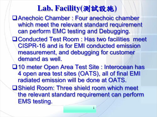
EMC Study and Testing of the VehicleM anagement S ystem in C lean E nergy A utomotive Ji Zhang* and ZeChang Sun,JingHua Li,Zhuo Zhang*** School of Automotive Studies Tongji University, Shanghai, CHINA. Email: jizhang@** School of Automotive Studies Tongji University, Shanghai, CHINA. Email: zhangzhuo1101@Abstract—Today, Electromagnetic Compatibility seems to be one of the major constraints of powertrain and especially for Clean Energy Automotive.The major purpose of paperis to get the veracity and repeatability of the testing results, and then to study the theory of RFI/EMI to resolve the interference resource and cut the interfering path. This paper will carry on the theory analysis and design analysis and EMC study aiming at the vehicle management system,at the same time introduce five imperative EMC tests of automotive components in details and analyse the measured results.Keywords—Vehicle Management System; RFI/EMI Testing; EMSCAN; EMC; PowertrainI.I NTRODUCTION Electromagnetic compatibility environment of the autoelectrical equipment may be coexistent and noninterferential, which calls for the system having good EMI and EMS characteristics. Three factors are indispensable to lead to electromagnetic interference which would degrade the function of electrical equipment or make it lapse: interference source, coupling path and sensitive equipment. And in order to solve the problem of EMC fundamentally, various ways must be taken to inhibit interference source, intercept the coupling path and enhance sensitive equipment Immunity. In the pages we carry on the analysis and study aiming at the vehicle management system EMC of Clean Energy Automotive, and at the same time introduce imperative EMC tests of important automotive components in details and analyse the test results.II.EMC A NALYSIS IN C LEAN E NERGY A UTOMOTIVEIn Clean Energy Automotive, the vehicle borne disturbance sources are the fuel cell engine, the fuel cell stack high-pressure system, the DC / DC, the charge and discharge of auxiliary battery, and the powertrain system, etc. The fast transient of voltage and current will generate radiation and noise, so the electronic equipment close to these devices may be in disorder. In particular the rapid rectifier, motor start and high pressure radiation of motor drive modules will cause conduction and radiation disturbances with higher field strength.Therefore, when designing the EMC in Clean Energy Automotive, we can research on the theory of primary interference source, sense organ and pipeline based on the theory of electromagnetic field initiation and propagation, and then we can build up mathematics model of EMC in automotive environments. According to the model research and simulation analysis, we can provide expected indicators of EMC of practical automotive systems.A.Mathematics model of EMC in automotiveenvironmentThe mathematics model of EMC is built up based on the mathematical equation of spatial electromagnetic field distribution which is established according to the electromagnetic field characteristics, Maxwell equation, and automotive appearance, etc. The model requires that some data, such as the shape parameters, and the number, location (location in and out), frequency and intensity of the interference sources, can be changed easily. The function of local electromagnetic screen and the effect of multiple reflection and refraction (transmission) of the automotive covering should also be considered.B.The automotive EMC simulation analysisThe simulation analysis of primary interference source, sense organ, etc based on the mathematics model of automotive EMC shows the spatial electromagnetic field distribution and confirms the amplitude frequency characteristic curve. The output of various methods of contrast curve can be based on the advantages and disadvantages of researching various EMC preventive methods in automotive working environment and the measures of restraining the disturbance initiation and propagation.The mathematical model established needs more than 3 simulation analyses of practical systems. Simulation analysis results should consist with the actual test results, and the maximum error of specific point cannot be beyond± 5 dB.Further FCV EMC design is based on this. The initial study of electromagnetic compatibility design should be conducted:The analysis of the interference source (the initiation, nature and characteristic of interference);The transmission mode and approach of interference signal;Interference Effects (the corresponding response characteristics between equipment and interference signal);Methods and measures to limit interference;The measurement and calculation of interfere; Simulation of interference (reappearance of interferencecondition and simulation of interference mechanism);978-1-4244-1849-7/08/$25.00○C2008 IEEEImmunity test expected (limit of interference, testing method and evaluation criteria).There are two kinds of interference sources in driving vehicles. One is the radiation disturbance source outside vehicles, and the other is inside. Its manifestation is mainly based on the spectrum characteristic of the interference source, for instance, the narrow band interference sources, such as radios, receivers, industrial high-frequency generators, etc; The intermittent broadband interference sources, such as the internal combustion engine vehicles passing by, high-altitude (underground) high-tension lines, rectifier motors , etc; the transient broadband interference sources, such as electrostatic discharge, LEMP (Lightning Electro Magnetic Pulse), etc.There is no active protective measure for the outside interference sources, so the EMC design for the vehicle is a passive protection design, namely, the transmission modes and defensive capabilities. For the interference sources in vehicles, interference sources of the interference parts can be restrained by the usage of screen, buffers, and soft-switching.There are several ways of electromagnetic coupling approaches, which include electrical couplings with resistive and capacitive characteristics, magnetic couplings with inductive characteristics and radial couplings with the characteristics of high-frequency radiation. Interferences in vehicle, such as the start-up and acceleration of the fuel cell engine, the charge and discharge of the auxiliary power supply and the motor driver power of the powertrain system, will interfere with the devices nearby with the mode of electrical couplings or emit conduction disturbances to interfere with power lines, as well as other parts of communications and entertainments like radios in vehicles. The devices, such as the high-pressure fuel cell stack system and DC / DC, will have strong RF radiation in the work mode conversion. If the standard limit is exceeded, a radial pollution will be generated to outside.In Clean Energy Automotive, a number of radios, audio entertainment systems, navigation equipments and some low-voltage, micro-signal controllers are electromagnetic sensitive devices and may be damaged by the transient interference or electrostatic discharge. According to the characteristics of the interference source, the methods of screen, spectrum spread and common grounding can be taken to enhance electromagnetic defensive capabilities. III.EMC D ESIGN OF V EHICLE M ANAGEMENT S YSTEMIN C LEAN E NERGY A UTOMOTIVEVMS, namely, the powertrain controller, as the vehicle management center, mainly includes functions, such as the control of driving torque, the optimization control of braking energy, the automotive energy management, the maintenance and management of CAN network, the diagnosis and treatment of fault, the surveillance of automotive state and etc. It plays a role in controlling the operation of vehicles.There are serious interferences in the VMS applicable environment where a variety of noises and coupling approaches exists. Therefore the VMS has not only perfect functions but also strong anti-jamming capability. The following EMC design methods can be used to inhibit it. A.GroundingThe grounding of VMS primarily aims at resisting the outside interferences, so it is a signal grounding. It adopts a "full grounding" approach, which means all of the places are grounded, except the room occupied by transmission wires and components, to reduce the resistances and also to play a role in screen. The distance between the earth wire and the signal wire is only the distance among the wiring board layers. The high-frequency circuit always chooses the shortest path of signal loop to flow. Therefore, the actual current always flows in the surface the earth wire below the signal wire. Thus the smallest signal loop is formed naturally to reduce the difference-mode radiation.B.IsolationThe electromagnetic isolation of VMS adopts the whole photoelectric isolation of input and output. Because of the optocoupler with a low impedance input (generally 100Ωto 1KΩ) and a strong interference, the interference voltage transmitted to the optocoupler becomes low. Because the internal resistance of interference source is very high, the interference voltage with low energy could only produce weak current, which is not strong enough to make the diode light; although it has very high voltage, the interference could not generate enough energy to make the diode light; therefore, the interference is restrained. The optocoupler operates in a sealed tubal crust, so it doesn’t suffer from the outside influence.C.FilterThe main factors that cause the VMS out of work are the sensor fault and external interference signal. For analog signals, the normal output is in a certain scope, so when designing the EMC, we usually adopt low pass filters to stop the high-frequency signals.Additionally, the high-speed jumping digital signal will produce the impedance noise, so when designing the EMC of the VMS, the method of adding filters to the power ports is usually used to suppress the power noise. The large-capacity capacitor is used as the high-pass filter, and the small one as the low-pass filter.D.PCB designThe circuit template of the VMS adopts the design of six layers of circuit board, compared with the double-sided PCB, adding up the earth layer and power layer. The power plane should be closed to the grounding plane and below the grounding plane. Thus the grounding plane can play a shielding role to the radiation current distributed on the grounding plane. The power layer and the narrow space between the signal wire and the grounding wire can reduce the common-mode impedance and inductance coupling. Because of the little crosstalk between signal wires of two layers and the narrow space between the power layer and the grounding layer, the impedance is very low and suitable for power noise decoupling.E.Other methodsThe highly integrated circuit components can reduce the number of components on the PCB and simplify the layout of the PCB. As a result it can greatly reduce the failure rate and the probability of interference.Another one is the derating use of components. The derating design means the components working in lowerrated stresses, and the stresses impacting the system operation include: electric stresses (voltage, current, power, frequency and etc.), temperature, mechanical stresses. When the working stress is higher than rated stress, the failure rate will increase. A reasonable deratingis an effective method to improve the reliability of the components and parts.IV.EMC T ESTING OF V EHICLE M ANAGEMENTS YSTEM IN C LEAN E NERGY A UTOMOTIVEA.Emission measurementsAccording to the transmission routes, emissions can be divided into conduction emission and radiation emission. Both of the emission measurements follow the standardsof GB18655 and CISPR 25:”Limits and Methods of Measurement of Radio Disturbance Characteristics for the Protection of Receivers used on Board Vehicles”.1) Conduction emissionThe purpose of the test is to verify whether the controller will generate interferences beyond limits which may interfere with the other vehicle electronic components through the same power supply loop. The frequency measuring range is from 0.15 MHz to 108 MHz. The test layout is shown in Figures.1: the external lines of the controller should be well connected to meet the test conditions, and the power line length is 0.2 m.The test is based on GB18655-2002, chapter 4 of the first part, "General Requirements of Emission Measurement for Vehicles and Components/Modules"; chapter 6, “Test Equipments only for Components/Modules Test” and chapter 11 of the third part, “Conduction Emission of Components / Modules”; chapter 12 of the third part, “Limits of Conduction Disturbance of Components”. And the test is used to measure the interference intensity of conduction electric field produced by the power line of ECU, and ensure it under the set limits (TABLEⅠ).The test results are shown in Figures.2: parts of the results in the low frequency around 600k overstep the limit of class 1, and in the high frequency from 30M to 108M, they all overstep the limit of class 1.Figure 1. Test layout of conduction emission1—storage cell; 2—line artificial-mains network and load; 3—measuring instrument; 4—controller; 5—grounded plane; 6—testing line pencil; 7—insulating layer (50mm); 8—coaxial cable(50Ω)TABLE I.L IMITS OF CONDUCTION EMISSIONclassLimits of conduction emission (dB/μV)0.15MHz-0.3MHz0.53MHz-2.0 MHz5.9MHz-6.2MHz30MHz-54MHz70MHz-108MHzP P P PP1 90 66 57 52 42Figure2. Conduction emission measurement2) Radiation emissionThe purpose of the test is to detect whether the radiationdisturbance will interfere with the vehicle wirelesscommunications and other electrical devices. Thefrequency measuring range is 0.15 ~ 960 MHz. Thetesting layout is shown in Figure.3: the peripheral circuitof the controller should be well connected to meet the testconditions. The length of the power line and signal wire is1.5m.The test follows the standard of GB18655-2002,chapter 4 of the first part, "General Requirements ofEmission Measurement for Vehicles and Components /Modules"; chapter 6, “Test Equipments only forComponents / Modules Test” and chapter 13 of the thirdpart, “Radiation Emission of Components / Modules”;chapter 14 of the third part, “Limits of RadiationDisturbance of Components”. And the test is used tomeasure the interference intensity of radiation electricfield of ECU, ensure it under the set limits (TABLE Ⅱ)and simultaneously avoid interfering with other electricalsystems inside the vehicle.The test results are shown in Figures.4, Figures.5 andFigures.6: The tested ECU measures up to the standardlimit in the low frequency band, while around 80M and400M in the high frequency band, vertical polarization, itoversteps the limit of class 3.Figure3. Test layout of radiation emission1—measurement receiver; 2—absorbing shielding room; 3—separator connector; 4—double layers shielding coaxial cable; 5—antenna; 6—controller; 7—testing line pencil; 8—line artificial-mains network; 9—experimental table; 10—radio frequencyabsorbing materials; 11—power filterTABLEⅡL IMITS OF RADIATION EMISSIONclassLimits of radiation emission (dB/μV)0.15MHz-0.3MHz0.53MHz-2.0 MHz5.9MHz-6.2MHz30MHz-54MHz70MHz-960MHzP QP P QP P QP P QP P QP3 76 63 67 54 48 35 48 35 37 24Figure4.Radiation emission measurement in low frequency band(0.15~30MHz)Figure5. Radiation emission measurement in high frequency band(30~300MHz; horizontal polarization )Figure6.Radiation emission measurement in high frequency band (300~1000MHz; vertical polarization )B. Immunity measurements 1) Bulk current injectionThe purpose of the test is to detect whether the discharge and strong magnetic radiation from the other vehicle controllers will make the control performance depreciation or lapse. The testing standard is ISO11452:”Road ISO Vehicles-Electrical Disturbances by Narrowband Radiated Electromagnetic Energy-Component Test Method”. The current frequency range is 1~400MHz, continuous sine wave modulation, 1KHz 80% and current residence time is longer than 1 second. Testing distance is 1.5 m. The testing layout is shown in Figure.7: the test is done by the usage of the set current class and increasing the induction signal frequency, and the current injection probe is induced on the connection line pencil directly.As the controller is metal sealed, the whole controller has a good anti-interference screen. It has a strong immunity against the outer electromagnetic radiation, so the most probable interference for the controller is the radiation or conduction interference produced by various feedback lines.According to part 4 of ISO11452:”Bulk Current Injection”, the test is to verify the immunity of the ECU when the interference is a common mode current produced by radiation electromagnetic field. Test result is A, shown in Table Ⅲ.2) Electrical transient conduction immunityThe purpose of the test is to verify the ability of every working controller to resist the interference of varied transient pulses which would appear when controllers work in the same power supply circuit, such as charge anddischarge of the power; high-power motor start; engineFigure7. Test layout of bulk current injection1—tested controller; 2—testing line pencil; 3—analog load; 4—observation device; 5—power supply; 6—line artificial-mains network; 7—optical fiber; 8—radio frequency transmitter; 9—radio frequency feedback probe; 10—radio frequency injection probe; 11—grounded plane; 12—insulator; 13—shielding room;d—distance between tested controller and radio frequency injection probeTABLE ⅢTEST RESULTS OF BULK CURRENT INJECTIONTesting state of specimen: normal (fan loads )Dwell time: 3s Working voltage oftest: DC + 13.5V Stepping:1~10MHz:1MHz ;10~200MHz:2MHz ;200~400MHz:20MHzModulation :CW ;AM ,80% Class (mA) Distance toEUT (mm )Frequency range (MHz ) Perform-ance criterion Testing result100 120,450,750 1~400 A Accordstart, etc. The testing standard is ISO11452:”Road Vehicles-electrical Disturbances by Conduction and Coupling”. The testing layout is shown in Figure.8. The controller meets the testing conditions. Then the following tests have been done by simulating various vehicle field interferences:① The test for the power lines is designed by five methods, 1, 2a, 2b, 4 and 5 of ISO7637.② The test for CAN and I/O port is designed by the methods of 3a and 3b of ISO7637.Other electrical apparatus (or equipments) in the same power supply circuit would produce transient disturbance pulse group when working, and the turnon or turnoff of certain high-power motors would produce transient disturbance pulse surge, which may reduce the voltage of the whole power system. All these interferences may make the controller lapse. In addition, engine starter motor excitation would lead to voltage drop of the entire power supply system and directly interfere with the controller. Therefore, this test must be done to verify the immunity. According to part 2 of ISO7637:” Commercial Vehicles with Nominal 24V Supply Voltage-Electrical Transient Conduction along Supply Lines Only”, the testing item is to verify the ECU immunity against transient conduction electromagnetic field interferences.Figure.9 shows the transient voltage interference waveform, and the measured results are eligible, shown in T ABLE Ⅴ.Figure8. Test layout of electrical transient conduction immunity 1—waveform generator; 2—voltage probe; 3—line artificial-mains network; 4—tested equipment; 5—grounded plane;6—power supply; 7—grounding lineFigure.9 transient interference waveformTABLE ⅣP ARAMETERS IN F IGURE .9parameter 12V system Us -112V — -150VRi 50t6 )1.0(1.00us tr 5ns ±1.5nst1 100 t4 10ms t5 90msTABLE ⅤT EST RESULTS OF ELECTRICAL TRANSIENT CONDUCTION IMMUNITYTesting state of specimen:normal operation (fan loads)Working voltage of test:DC + 13.5V (pulse 4 is12V )Coupling line: power line Coupling approach: CDNTesting waveform Class /polarity Pulse numberTesting timePulse cycle Performance criterionPulse 1 -75 V 1000 / 2s BPulse 2a +35 V 1000 / 1s A Pulse 2b +10 V 10 / 5s B Pulse 3a -112V / 1800s 100ms A Pulse 3b +75 V / 1800s 100ms A Pulse 4 -6 V 1 / 2s B Pulse 5+65 V1 / 45sA3) Electrostatic dischargeThe test is to verify whether the heavy current and strong magnetic field produced by body contaction or object discharge nearby will damage the controller. The reference standard is ISO10605:” Road Vehicles-Electrical Disturbances from Electrostatic Discharge”. Testing voltage, discharge times and discharge interval separately are ±15KV, 3 times and 5 seconds. The test layout is shown in Figure.10: make sure the controller is out of work and adopt indirect discharge. The discharges to the coupling plate near the tested object are carried out by the discharge gun. Test result is show in TABLE Ⅵ.Figure10. Test layout of electrostatic dischargeTABLE ⅥTEST RESULTS OF ELECTROSTATIC DISCHARGETesting state of specimen: no electric charges Power type: DC 12V Discharge times: 3 times plus and minus / position Discharge interval: 5s Discharge mode Discharge position Class (KV) Testing phenomenon Performance criterion Direct discharge (air discharge ) Stitch 15 Normal work after electified BThe high voltage electrostatic discharge may produce heavy current, high voltage and strong magnetic field when the body or other objects closing to or contacting the surface of the electrical equipment, which may make the electrical equipments ineffective or even lose their functions. In other words, electrostatic discharge may interfere with the working equipments or systems and even damage them, so it is necessary to do the immunity test for electrostatic discharge for the VMS.According to part 5 of ISO10605:” Test Procedure for Electronic Module”, the purpose of the test is to verify the ECU immunity to resist electrostatic discharge produced by body. The measured result satisfies the standard. V. C ONCLUSIONSThe test results of conduction and radiation emission overstep the class 2 limits. The improvement measures are based on the measured results and analyses.A. Analyses and improvements for conduction emission The reasons for the over standard of conduction disturbance emission might include: 1. The DC / DC converter working in the switching power supply circuit at pulse state would lead to strong interference; 2. The working current of the digital circuit in the controller circuit board is transient. Although decoupling capacitors are set on every circuit board and beside every circuit chip, part of the transient current will still interfere with the power supply, transmitting along the power line. 3. The internal circuit board of the controller will likely generate radiation, whose energy will be induces into power lines and power supply circuit itself, forming conduction emission.In order to improve characterization of conduction emission, power line filters with better high-frequency performance should be installed at the entrance of the power line; otherwise it would lead to the problem of radiation emission. To find the possible jamming areas of high-frequency currents and radiations, we use near-field probe and spectrum analyzer or specialized near-field scanner (e.g., EMSCAN) to scan the circuit board. We fix suitable decoupling capacitors and improve the circuit board layout to solve these problems. The modified controller satisfies the class 2 limits and the test result is shown in Figure 11.B.Analyses and improvements for radiation emission The reasons for the over standard of radiation disturbance emission might include: 1. The external non-shielded cable of the controller, without filtering, may become radiation source because of its potential common mode current; 2. Power lines with undesirable high-frequency filtering may be caused by power line with no filters or the filters with bad high-frequency performance;3. The shielded cable with bad shielding layer terminations may be caused by misconnecting the shielding layer or not contacting the terminals in accordance with the principle of 360° termination;4. Leaks will be formed by the cracks or holes in the shielding shell of the controller.The following measures are taken: the layers of PCB increase from 6 to 8 and the high-frequency noise is decoupled by the coupling capacitance formed between integrated power supply and ground;meliorate the layout of the circuit board and place the components more reasonably to prevent the interference between different circuits; some electromagnetic interference suppression components are added. The test results of the radiation emission before and after revised are shown in Fig.12. They show that these measures greatly reduce the intensity of radiation and improve the electromagnetic compatibility.Frequency scanning result of the revised circuit board is shown in Fig.13: the harmonic order is quite high, and the highest one based on 40MHz is 25th or even more. The reason is that the data bus and address bus between U26 [CY7C1347B] and U1B [MPC555LFMZP40] do not take into account impedance matching and EMC. And the impedance matching between A2-A20 and D0-D31 should be added (Propositional resistance is 33ohm and it should be adjusted according to the actual test result). And Figure14 shows that the controller has measured up to the class 2 limits.Figure11. Final conduction emission measurementFigure12.Radiation emission measurement(the right one is the modified one)Figure13. Frequency scanning on the revised circuit boardFigure14. Final radiation emission measurement in high frequencyband (vertical polarization, wideband)C.Rectification measuresAiming at the analyses of the tests above, the following improvement measures for the controller PCB are adopted: 1. A common mode filter (ACM1211 produced by TDK) for the power line, is fixed at the entrance of the PCB power (12V supply); 2. In the power circuit, a magnetic bead (HF××575018 produced by TDK) is fixed at the entrance of the circuit transforming 5V into 3.3V; 3.A special common mode filter for CAN (ACT45B-510-2P produced by TDK) should be added to the bus interface. With the above measures adopted, tests can be passed.R EFERENCES[1]Henry W.Ott. Noise Reduction Techniques In Electronic System(Second Edition),John Wiley & Sons, Inc.1998.[2]Tim Williams.EMC for PRODUCT Designers[M]. 4th ed.Elsevier Science Ltd,2007.[3]Clayton R.Paul. Introduction to Electromagnetic Compatibility(Second Edition), John Wiley & Sons, Inc.2006[4]Mark I. Montrose, Edward M. Nakauchi. Testing for EMCCompliance: Approaches and Techniques, The Institute of Electrical and Electronics Engineers,Inc.2004.[5]IEC CISPR 25—Limits and methods of measurement of radiodisturbance characteristics for the protection of receivers used onboard vehicles.[6]ISO 11452—Road vehicles — Component test methods forelectrical disturbances from narrowband radiated electromagnetic energy —Part 4:Bulk current injection (BCI).[7]ISO 11452—Road vehicles — Component test methods forelectrical disturbances from narrowband radiated electromagnetic energy —Part 2: Absorber-lined shielded enclosure.[8]ISO 7637—Road vehicles— Electric disturbances by conductionand coupling—Part 2:voltage-Electrical transient conduction alongsupply lines only.[9]ISO 10605—Road vehicles—Test method for electricaldisturbances from electrostatic discharge—Part 5:Test procedure for electronic module.。