进口SMC旋转气缸说明书
- 格式:doc
- 大小:1.38 MB
- 文档页数:7

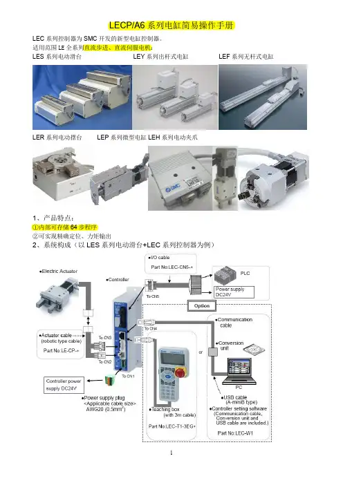
LECP/A6系列电缸简易操作手册LEC系列控制器为SMC开发的新型电缸控制器。
适用范围LE全系列直流步进、直流伺服电机:LES系列电动滑台LEY系列出杆式电缸LEF系列无杆式电缸LER系列电动摆台LEP系列微型电缸LEH系列电动夹爪1、产品特点:①内部可存储64步程序②可实现精确定位、力矩输出2、系统构成(以LES系列电动滑台+LEC系列控制器为例)3、产品结构4、各端口配线及功能详解4-1 CN1端口-DC24V电源接口4-1-1急停信号配线:(注意:常闭信号,闭合时正常使用,断开时急停)4-1-2解锁信号配线:(注意:闭合时解锁,断开时锁紧,适用于带锁型电缸手动解锁用,运动时无需解锁)4-2 CN2端口-电机电源接口/CN3端口-电机编码器接口/CN4端口-通信线缆接口以上3个端口均为标准插头,直接插入端口即可。
4-3 CN5端口-控制I/O 接口 CN5端口用标准线缆示意图:配线图(以NPN 型为例)注意:上表中粗体红字部分的线为必接线,否则电缸无法正常使用。
其余线缆可根据实际需要选接。
输出信号:5、编程软件的安装、使用5-1 编程软件的安装①将软件安装盘放入电脑光驱,然后用通信线缆将电脑与控制器联接。
②系统出现入如图所示提示,按照图中红圈指示操作。
③点击“NEXT”后将出现如下界面,按照图中红圈指示操作。
④点击“NEXT”后将出现如下界面,按照图中红圈指示操作。
⑤点击“FINISH”,完成软件安装。
⑥安装完成后,桌面上将出现如下图标。
双击即可进入编程软件。
5-2 通信端口匹配①在桌面的“我的电脑”图表上点击鼠标右键,选择“属性”,出现如下界面,按红圈指示操作。
②点击“设备管理器”查看系统分配给LEC系列控制器的端口编号(例:COM4),记录下来。
注意:如果在“设备管理器”下面的“端口(COM&LPT)”一栏下没有发现SMC产品项及端口号,请检查“设备管理器”界面下的“端口(COM&LPT)”及“通用总线串行控制器”两项中有无黄色问号项,如果有,则驱动未能完全安装。
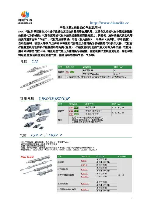
产品名称:原装SMC气缸说明书
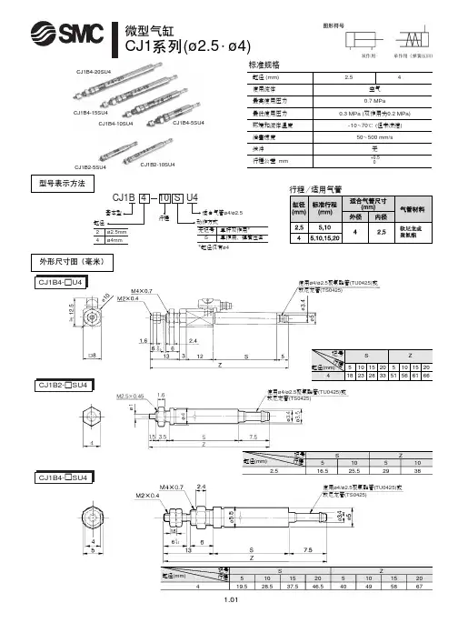
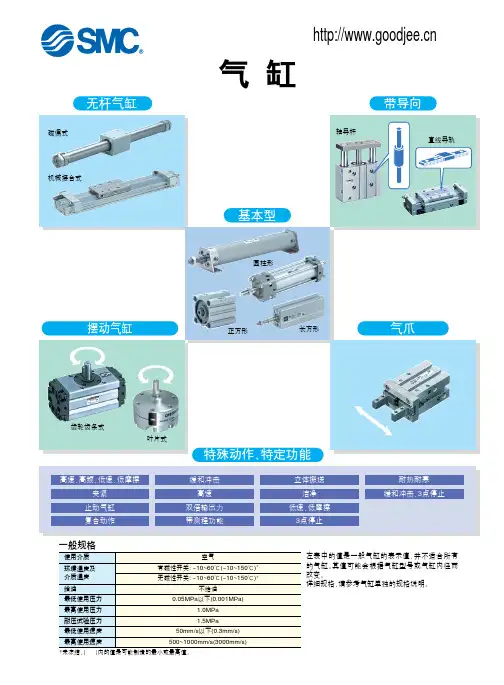
SMC气缸引导活塞在其中进行直线往复运动的圆筒形金属机件。
工质在发动机气缸中通过膨胀将热能转化为机械能;气体在压缩机气缸中接受活塞压缩而提高压力。
涡轮机、旋转活塞式发动机等的壳体通常也称“气缸”。
气缸的应用领域:印刷(张力控制)、半导体(点焊机、芯片研磨)、自动化控制、机器人等等,气压传动中将压缩气体的压力能转换为机械能的气动执行元件。
气缸有作往复直线运动的和作往复摆动的两类(见图)。
作往复直线运动的气缸又可分为单作用、双作用、膜片式和冲击气缸4种。
将压缩空气的压力能转换为机械能,驱动机构作直线往复运动、摆动和旋转运动,直线运动往复运动的气缸、摆动运动的摆动气缸、气爪等。
LECP/A6系列电缸简易操作手册LEC系列控制器为SMC开发的新型电缸控制器。
适用范围LE全系列直流步进、直流伺服电机:LES系列电动滑台LEY系列出杆式电缸LEF系列无杆式电缸LER系列电动摆台LEP系列微型电缸LEH系列电动夹爪1、产品特点:①内部可存储64步程序②可实现精确定位、力矩输出2、系统构成(以LES系列电动滑台+LEC系列控制器为例)3、产品结构4、各端口配线及功能详解4-1 CN1端口-DC24V电源接口4-1-1急停信号配线:(注意:常闭信号,闭合时正常使用,断开时急停)4-1-2解锁信号配线:(注意:闭合时解锁,断开时锁紧,适用于带锁型电缸手动解锁用,运动时无需解锁)4-2 CN2端口-电机电源接口/CN3端口-电机编码器接口/CN4端口-通信线缆接口以上3个端口均为标准插头,直接插入端口即可。
4-3 CN5端口-控制I/O 接口 CN5端口用标准线缆示意图:配线图(以NPN 型为例)注意:上表中粗体红字部分的线为必接线,否则电缸无法正常使用。
其余线缆可根据实际需要选接。
输出信号:5、编程软件的安装、使用5-1 编程软件的安装①将软件安装盘放入电脑光驱,然后用通信线缆将电脑与控制器联接。
②系统出现入如图所示提示,按照图中红圈指示操作。
③点击“NEXT”后将出现如下界面,按照图中红圈指示操作。
④点击“NEXT”后将出现如下界面,按照图中红圈指示操作。
⑤点击“FINISH”,完成软件安装。
⑥安装完成后,桌面上将出现如下图标。
双击即可进入编程软件。
5-2 通信端口匹配①在桌面的“我的电脑”图表上点击鼠标右键,选择“属性”,出现如下界面,按红圈指示操作。
②点击“设备管理器”查看系统分配给LEC系列控制器的端口编号(例:COM4),记录下来。
注意:如果在“设备管理器”下面的“端口(COM&LPT)”一栏下没有发现SMC产品项及端口号,请检查“设备管理器”界面下的“端口(COM&LPT)”及“通用总线串行控制器”两项中有无黄色问号项,如果有,则驱动未能完全安装。
VR12F-TF222-005ENPage 1 of 1Instruction ManualAND Valve with One-touch FittingsThe intended use of this product is to control pneumatic signal lines.These safety instructions are intended to prevent hazardous situations and/or equipment damage. These instructions indicate the level of potential hazard with the labels of “Caution,” “Warning” or “Danger.” They are all important notes for safety and must be followed in addition to International Standards (ISO/IEC) *1), and other safety regulations. *1)ISO 4414: Pneumatic fluid power - General rules relating to systems. ISO 4413: Hydraulic fluid power - General rules relating to systems.IEC 60204-1: Safety of machinery - Electrical equipment of machines. (Part 1: General requirements)ISO 10218-1: Robots and robotic devices - Safety requirements for industrial robots - Part 1: Robots.• Refer to product catalogue, Operation Manual and Handling Precautions for SMC Products for additional information. • Keep this manual in a safe place for future reference.Warning • Always ensure compliance with relevant safety laws and standards.• All work must be carried out in a safe manner by a qualified person in compliance with applicable national regulations.2 SpecificationsNote 1) Use caution when the maximum operating pressure is used with soft nylonand polyurethane. Depending on the temperature, these tubes have a lower operating pressure. Refer to the specification of the tubes.Note 2) Two axes (horizontal and vertical) and two directions were tested, and nomalfunction of the valve occurred (pulse shape: sine shape), 3 times (test sample mounted with bracket).Note 3) No malfunction occurred in a sweep cycle test between 10 to 150 Hz atvibration sweep 0.35 mm. The test was performed in the two axes and two directions, 7 min per cycle (20 cycles).Note 4) Brass components are all electroless nickel plated as standard. (Copper-free and fluorine-free)2.2 Response timeValve response time depends on the overall circuit design, so it must be determined by the circuit designer. 2.3 Special productsWarningSpecial products (-X) might have specifications different from those shown in this section. Contact SMC for specific drawings.3 Installation3.1 InstallationWarning• Do not install the product unless the safety instructions have been read and understood. 3.2 EnvironmentWarning• Do not use in an environment where corrosive gases, chemicals, salt water or steam are present.• Do not use in an explosive atmosphere.• Do not expose to direct sunlight. Use a suitable protective cover.• Do not install in a location subject to vibration or impact in excess of the product’s specifications.• Do not mount in a location exposed to radiant heat that would result in temperatures in excess of the product’s specifications.• Do not use in high humidity environment where condensation can occur.• Contact SMC for altitude limitations.3.3 Operating pressure conditions• Only when air is supplied to both P1 and P2 does air flow to the OUT side.• When air pressure differs, the lower pressure flows to the OUT side.Figure 1.• If air is supplied only to either P1 or P2, it does not flow to the OUT side.Figure 2.Warning• Air may flow to the OUT side for a moment until the valve switches (About 1/100 second). If there is any effect on the connected equipment due to the above air flow, install a speed controller, etc, on the OUT side, and adjust to prevent this effect before use.3.4 PipingCaution• Before connecting piping make sure to clean up chips, cutting oil, dust etc.• When installing piping or fittings, ensure sealant material does not enter inside the port. When using seal tape, leave 1 thread exposed on the end of the pipe/fitting.• Stop using the equipment immediately when air leaks are large enough to be audible, or when the equipment does not operate properly. Perform appropriate function and leakage tests.• Check periodically that piping is not loosened and that there is no air leakage.• Regularly check that there is no external damage.• When connecting tubes using One-touch fittings, provide some spare tube length.• Do not apply external force to the fittings when binding tubes with bands.Caution• SMC products have been lubricated for life at manufacture, and do not require lubrication in service.• If a lubricant is used in the system, refer to catalogue for details. 3.5 Air supplyWarning• Use clean air. If the compressed air supply includes chemicals, synthetic materials (including organic solvents), salinity, corrosive gas etc., it can lead to damage or malfunction.Caution• Install an air filter upstream of the valve. Select an air filter with a filtration size of 5 μm or smaller.4 How to OrderRefer to catalogue for ‘How to Order’.5 Outline DimensionsRefer to catalogue for outline dimensions.6 Maintenance6.1 General maintenanceCaution• Not following proper maintenance procedures could cause the product to malfunction and lead to equipment damage.• If handled improperly, compressed air can be dangerous.• Maintenance of pneumatic systems should be performed only by qualified personnel.• Before performing maintenance, turn off the power supply and be sure to cut off the supply pressure. Confirm that the air is released to atmosphere.• After installation and maintenance, apply operating pressure and power to the equipment and perform appropriate functional and leakage tests to make sure the equipment is installed correctly.• If any electrical connections are disturbed during maintenance, ensure they are reconnected correctly, and safety checks are carried out as required to ensure continued compliance with applicable national regulations.• Do not make any modification to the product.• Do not disassemble the product, unless required by installation or maintenance instructions.7 Limitations of UseWarningThe system designer should determine the effect of the possible failure modes of the product on the system.7.1 Limited warranty and disclaimer/compliance requirements Refer to Handling Precautions for SMC Products.Warning7.2 Effect of energy loss on valve state• The valve is an AND logic element in an all-air circuit. When the air pressure is cut to both inputs the valve goes into an undefined state. Backflow of air from out to in port may occur under this condition.• It is the responsibility of the system designer to determine the effect in the system when air pressure is cut and when it is restored. 7.3 Cannot be used as an emergency shut-off valveThis product is not designed for safety applications such as an emergency shut-off valve. If the valves are used in this type of system, other reliable safety assurance measures should be adopted.7.4 Holding of pressureSince valves are subject to air leakage, they cannot be used for applications such as holding pressure (including vacuum) in a system.Caution7.5 Low temperature operationUnless otherwise indicated in the specifications for each valve, operation is possible to -5˚C, but appropriate m easures should be taken to avoid solidification or freezing of drainage and moisture, etc.8 Product DisposalThis product shall not be disposed of as municipal waste. Check your local regulations and guidelines to dispose this product correctly, in order to reduce the impact on human health and the environment.9 ContactsRefer to or www.smc.eu for your local distributor/importer.URL : https:// (Global) https:// www.smc.eu (Europe) SMC Corporation, 4-14-1, Sotokanda, Chiyoda-ku, Tokyo 101-0021, JapanSpecifications are subject to change without prior notice from the manufacturer. © 2022 SMC Corporation All Rights Reserved. Template DKP50047-F-085MORIGINAL INSTRUCTIONS2 (OUT)(IN) 1 (IN) 1IN P 1 IN P 2 OUT OUTOUT IN P 1 IN P 2 IN P 1 IN P 2。
smc旋转气缸原理旋转气缸是一种常见的气动执行元件,能够将气压能转化为机械能,实现物体的旋转运动。
本文将详细介绍SMC旋转气缸的原理和工作过程。
一、SMC旋转气缸的结构组成SMC旋转气缸主要由气缸本体、活塞、活塞杆、传动装置、导向装置和密封装置组成。
气缸本体:通常采用圆筒形结构,外表面光滑,并且采用具有良好机械强度和刚度的材料制造,如铝合金。
活塞:位于气缸本体内,通过气体压力推动活塞实现旋转运动。
活塞杆:连接气缸本体和活塞,将活塞产生的转动力传递给传动装置。
传动装置:将气压能转化为机械能的装置,包括齿轮传动、斜齿轮传动等,根据具体设计有所不同。
导向装置:用于保证气缸的稳定运动,减少摩擦损失。
密封装置:用于保证气缸内气体不泄漏。
二、SMC旋转气缸的工作原理SMC旋转气缸利用气体的压力来推动活塞实现旋转运动。
1. 气源供气:气源通过管路连接到气缸的入口处,通过阀门控制气体的进出。
2. 气源供气并施加压力:打开阀门,气压进入气缸,气压使活塞受力,开始旋转。
3. 活塞旋转:气压推动活塞运动,活塞将产生的力矩通过活塞杆传递给传动装置,带动物体旋转。
4. 切换气源:当需要改变旋转方向时,切换气源的供气方向,使气压的作用方向反转,从而改变旋转方向。
5. 关闭阀门:当旋转到需要停止的位置时,关闭阀门,切断气源供气,气压减小,活塞停止旋转。
三、SMC旋转气缸的应用领域SMC旋转气缸具有结构简单、体积小、重量轻、使用方便等特点,被广泛应用于多个领域。
1. 机械制造:用于机械臂、自动化装配线等设备中,实现零部件的旋转定位。
2. 自动包装:用于自动包装机械中,将物品装入包装盒或者袋子中,实现自动包装。
3. 机床加工:用于机床中,实现工件夹持、夹紧、旋转等功能。
4. 电子设备制造:用于电子设备的焊接、组装、测试等环节,实现自动化生产。
5. 印刷设备:用于印刷机械中,实现纸张传送、定位、翻转等操作。
总结:SMC旋转气缸通过气压能将旋转运动转化为机械能,广泛应用于机械制造、自动包装、机床加工、电子设备制造、印刷设备等领域。
文件No.CM2*-OM0230Q气缸C*M2**-*ZC*M2**-*Z-XC85C*M2**-*Z-X446安全注意事项 P21. 产品规格P41-1. 规格2.设置方法・使用方法P42-1. 使用空气2-2. 设计注意事项2-3. 安装·设置2-4. 使用环境条件2-5. 速度控制2-6. 允许动能2-7. 方向控制2-8. 磁性开关3. 保养点检P173-1. 活塞杆密封圈的更换方法3-2.点检3-3. 消耗品4. 订制品(XC85,X446) P194-1. 食品机械用润滑脂规格4-2. PTFE润滑脂规格5. 气缸使用的基本回路 P206. 故障与对策 P217. 构造P23安全注意事项此处所示的注意事项是为了确保您能安全正确地使用本产品,预先防止对您和他人造成危害和伤害而制定的。
这些注意事项,按照危害和损伤的大小及紧急程度分为「注意」「警告」「危险」三个等级。
无论哪个等级都是与安全相关的重要内容,所以除了遵守国际规格(ISO/IEC)、日本工业规格(JIS)*1)以及其他安全法规*2)外,这些内容也请务必遵守。*1) ISO 4414: Pneumatic fluid power -- General rules relating to systemsISO 4413: Hydraulic fluid power -- General rules relating to systemsIEC 60204-1: Safety of machinery -- Electrical equipment of machines (Part 1: General requirements)ISO 10218-1992: Manipulating industrial robots-SafetyJIS B 8370: 空气压系统通则JIS B 8361: 油压系统通则JIS B 9960-1: 机械类的安全性-机械的电气装置(第1部:一般要求事项)JIS B 8433-1993: 工业用操控机器人-安全性等*2) 劳动安全卫生法等注意误操作时,有人员受伤的风险以及物品破损的风险。警告误操作时,有人员受到重大伤害甚至死亡的风险。
Other SettingsSummary of Product partsSimple Setting ModeTroubleshootingNote: Specifications are subject to change without prior notice and any obligation on the part of the manufacturer.© 2015 SMC Corporation All Rights ReservedAkihabara UDX 15F, 4-14-1, Sotokanda, Chiyoda-ku, Tokyo 101-0021, JAPANPhone: +81 3-5207-8249 Fax: +81 3-5298-5362URL Specifications/Outline with Dimensions (in mm)Refer to the product catalogue or SMC website (URL ) formore information about the product specifications and outline dimensions.PS※※-OMS0008-A InstallationMounting with bracketMount the bracket to the body with mounting screws (Self tapping screws:Nominal size 3 x 8L (2 pcs)), then set the body to the specified position.∗: Tighten the bracket mounting screws to a torque of 0.5±0.05 Nm.Self tapping screws are used, and should not be re-used several times.∗: The panel mount adapter can be rotated through 90 degrees for mounting.•Bracket A (Part No.: ZS-46-A1)•Bracket B (Part No.: ZS-46-A2)Mounting with panel mount adapterMount part (a) to the front of the body and fix it. Then insert the body with (a)into the panel until (a) comes into contact with the panel front surface. Next,WiringWiring connectionsConnections should be made with the power supply turned off.Use a separate route for the product wiring and any power or high voltagewiring. Otherwise, malfunction may result due to noise.If a commercially available switching power supply is used, be sure toground the frame ground (FG) terminal. If the switching power supply isconnected for use, switching noise will be superimposed and it will not beable to meet the product specifications. In that case, insert a noise filtersuch as a line noise filter/ferrite between the switching power supplies orchange the switching power supply to the series power supply.How to use connectorstraight out.OUT1NCNCDC(-)PipingTightening the connection threadFor connecting to the body (piping specification: -M5)After hand tightening, apply a spanner of the correctsize to the spanner flats of the piping body, and tightenwith a 1/6 to 1/4 rotation.As a reference, the tightening torque is 1 to 1.5 Nm.(When replacing the piping adapter ZS-39-N∗, tighten itusing the same method.)Piping specification: -01, -N01After hand tightening, hold the hexagonal spanner flatsof the pressure port with a spanner, and tighten with 2 to3 rotations.As a reference, the tightening torque is 3 to 5 Nm.When tightening, do not hold the Z/ISE20 body with aspanner.Default settingsWhen the pressure exceedsthe set value, the switch will beturned on. When the pressurefalls below the set value by theamount of hysteresis or more,the switch will be turned off.The default setting is to turn onthe pressure switch when thepressure reaches the centre of the atmospheric pressure and upper limit of therated pressure range. If this condition, shown to the right, is acceptable, then keepthese settings.Error indication functionThis function is to display error location and content when a problem or error has occurred.than above are displayed, please contact SMC.Refer to the SMC website (URL ) for more informationabout troubleshooting.button between1 and 3 sec.button between3 and 5 sec.∗:The outputs will continue to operate during setting.∗:If a button operation is not performed for 3 seconds during the setting, the display will flash.(This is to prevent the setting from remaining incomplete if, for instance, an operator were to leaveduring setting.)∗:3 step setting mode, simple setting mode and function selection mode settings are reflected eachother.[3 step setting mode (hysteresis mode)]orsetting can be changed in the same way.button once when the item toThe set value on the sub display (right) willstart flashing.orbutton and can be reduced withbutton.buttons are pressed and held simultaneously for 1second or longer, the set value is displayed as [- - -], and the set value will bethe same as the current pressure value automatically (snap shot function).button.button to complete the setting.The Pressure switch turns on within a set pressure range (from P1L to P1H) duringwindow comparator mode.Set P1L, the lower limit of the switch operation, and P1H, the upper limit of theswitch operation and WH1 (hysteresis) following the instructions given above.(When reversed output is selected, the sub display (left) shows [n1L] and [n1H].)∗:Setting of the normal/reverse output switching and hysteresis/window comparator modeswitching are performed with the function selection mode [F 1] OUT1 setting.valuePeak/bottom value indicationbutton inmeasurement mode.Snap shot functionbuttons for 1second or longer simultaneously. Then, the set value of the sub display (right)shows [- - -], and the values corresponding to the current pressure values areautomatically displayed.Zero-clear functionbuttons are pressed for 1 secondor longer simultaneously, the main display shows [- - -], and the reset to zero.The display returns to measurement mode automatically.Key-lock functionTo set each of these functions, refer to the SMC website(URL ) for more detailed information, or contact SMC.button between 1 and 3 seconds inmeasurement mode. [SEt] is displayed on the main display. Whenthe button is released while in the [SEt] display, the current pressurevalue is displayed on the main display, [P_1] or [n_1] is displayed onthe sub display (left), and the set value is displayed on the subdisplay (right) (Flashing).or button to set the(The snap shot function can be used.)or button to set the(The snap shot function can be used.)or button, the delay time of the switch output can be selected.button for 2 seconds or longer to complete the OUT1 setting.∗:If the button is pressed for less than 2 seconds, the setting will be returned to P_1.In the window comparator mode, set P1L, the lower limit of the switch operation,and P1H, the upper limit of the switch operation, WH1 (hysteresis) and dt1 (delaytime) following the instructions given above.(When reversed output is selected, the sub display (left) shows [n1L] and [n1H].)Function selection modebutton between 3 and 5seconds, to display [F 0]. Select todisplay the function to be changed[F]. Press and hold the buttonfor 2 seconds or longer in functionselection mode to return tomeasurement mode.∗:Some products do not have all the functions. If no function is available or selected due toconfiguration of other functions, [- - -] is displayed on the sub display (right).Names of individual partsRefer to the product catalogue or SMC website (URL )for more information about panel cut-out and mounting hole dimensions.Pressure Setting3 Step Setting Mode(URL ) for more detailed information, or contact SMC.MaintenanceHow to reset the product after a power cut or forcible de-energizingThe setting of the product will be retained as it was before a power cut orde-energizing. The output condition is also basically recovered to that before apower cut or de-energizing, but may change depending on the operatingenvironment. Therefore, check the safety of the whole installation before operatingthe product. If the installation is using accurate control, wait until the product haswarmed up (approximately 10 to 15 minutes).Safety InstructionsBefore UseDigital Pressure SwitchZSE20(F)/ISE20Thank you for purchasing an SMC ZSE20(F)/ISE20 Series Digital PressureSwitch.Please read this manual carefully before operating the product and make sure youunderstand its capabilities and limitations. Please keep this manual handy forfuture reference.Safety InstructionsThese safety instructions are intended to prevent hazardous situations and/orequipment damage.These instructions indicate the level of potential hazard with the labels of"Caution", "Warning" or "Danger". They are all important notes for safety and mustbe followed in addition to International standards (ISO/IEC) and other safetyregulations.OperatorSwitch ONAt normal output Switch OFFSet valueP_1HysteresisH_1TimePressureOther parameter settingsDefault settingThe default setting is as follows.If no problem is caused by thissetting, keep these settings.。
!"# E !"#$FL MSUB ( !: 1, 3, 7, 20)!MSUB7MSUB3MSUB1MSUB20有效输出力矩表度或损害结构)轴向安装单叶双叶双叶单叶双叶单叶双叶单叶使用压力MPa使用压力MPa使用压力MPa使用压力MPa 最适合在机械手上使用。
重量轻、体积小的摆动气缸。
加大滑动轴承,负载比CRB1系列大2至3倍。
多面安装设计。
※2 摆台与小型叶片式摆动气缸对照表※1 单叶片90… :可调整角度90… ±10… (两端调整±5… )单叶片180… :可调整角度180… ±10… (两端调整±5… )双叶片90… :可调整角度90… ±5… (两端调整±2.5… )侧面安装正面安装多种安装形式力矩Nm力矩Nm力矩Nm力矩Nm两端角度(单叶片±5°、双叶片±2.5°)可任意调节。
*****角度调节螺钉*其它尺寸请参照单叶片式。
*1)24: 当使用D-S99, T99时30: 当使用D-97, 93A 时*2) 60°: 当使用D-97, 93A 时69°: 当使用D-S99, T99时MDSUB1-□S(单叶片式,内置磁环型)MDSUB1-□D(双叶片式,内置磁环型)MSUB1-□D(双叶片式)4-M3x0.5深5长沉孔深5(定位用)2-4.5通孔2-4.50.59.52-M3×0.52-M3×0.52-M3×0.5通孔2-4.5通孔2-M4x0.7深82-4.5通孔MSUB1-□SE*其它尺寸请参见单叶片式。
角度调节螺钉调节最大5.752-M4x0.7深82-M3x0.5深4供气口"A"供气口"B"供气口"A"供气口"B"供气口"A"供气口"B"供气口"A"供气口"B"供气口位置在本体侧面供气口"A"供气口"B"CA27B3-3H9 深5+0.025+0.0250( , , )A B C 8.52.52.5914.73281214.52424.72.52.54.750.5512.5□31□3814.51122.5°22.5°2.5H9ø25ø51ø36h9 0-0.062ø36h9 0-0.062ø36h9 0-0.062ø35h9 0-0.062ø17H9+0.043ø35h9 0-0.062ø17H9+0.043ø4g6 -0.004-0.012ø9h9 0-0.036ø29ø36h9 0-0.062ø4g6 -0.004-0.012ø9h9 0-0.036ø292714.524(17)4114.721(8)27供气口位置在本体侧面3214.72830*12-M3×0.5D-97/93A24*1ø18.5ø29ø18.5ø29284114.72-M3×0.5*260°(69°)159942-øBB 孔长沉孔:深5(对位用)角度调节螺钉调节,最大KK供气口“A ”供气口“B ”720MSUB -□S, D (基本型)MSUB -□SE,DE (轴向供气口)2-∏孔供气口“A ”供气口“B ”2-øV 通孔3720(mm)供气口位置在本体侧面角度调节螺钉供气口“A ”供气口位置在本体侧面20.5 (26.5 插座式)供气口"A"角度调节螺钉插座式(34.5 电线接头型)2-M5 x 0.82-M5 x 0.8插座式*1) 24: 当使用D-S99, T99时30: 当使用D-97, 93A 时*2) 60°: 当使用D-97, 93A 时69°: 当使用D-S99, T99时供气口"B"供气口“B ”MDSUB7, 20(内置磁环型)D-97/93A规格型号叶片形式摆动角度使用流体环境及流体温度使用压力范围(MPa)摆动时间可调范围轴承接管口径摆动精度允许轴负载空气(不给油)5~60℃0.07~0.3 s/90°特殊轴承0.03mm 以内90°±10°MSUA1MSUA30.15~0.70.2~0.7M3×0.520 15 0.340 300.750 60 0.960 80 2.9M5×0.8M3×0.5M5×0.80.15~1.0MSUA7MSUA20180°±10°90°±10°180°±10°90°±10°180°±10°90°±10°180°±10°本体侧面轴向径向(N)轴向(N)力矩(N •m)MSUA MDSUA -□S单叶片13MDSUA -□720 !"#E !"#$FL !MSUA ( !: 1, 3, 7, 20)!。
产品名称:进口SMC旋转气缸说明书
SMC气缸引导活塞在其中进行直线往复运动的圆筒形金属机件。
工质在发动机气缸中通过膨胀将热能转化为机械能;气体在压缩机气缸中接受活塞压缩而提高压力。
涡轮机、旋转活塞式发动机等的壳体通常也称“气缸”。
气缸的应用领域:印刷(张力控制)、半导体(点焊机、芯片研磨)、自动化控制、机器人等等,气压传动中将压缩气体的压力能转换为机械能的气动执行元件。
气缸有作往复直线运动的和作往复摆动的两类(见图)。
作往复直线运动的气缸又可分为单作用、双作用、膜片式和冲击气缸4种。
将压缩空气的压力能转换为机械能,驱动机构作直线往复运动、摆动和旋转运动,直线运动往复运动的气缸、摆动运动的摆动气缸、气爪等。