(完整版)ABBDCS系统培训
- 格式:ppt
- 大小:12.52 MB
- 文档页数:62

S4C IRB 基本操作培训教材目录1、培训教材介绍2、机器人系统安全及环境保护3、机器人综述4、机器人启动5、用窗口进行工作6、手动操作机器人7、机器人自动生产8、编程与测试9、输入与输出10、系统备份与冷启动11、机器人保养检查表附录1、机器人安全控制链附录2、定义工具中心点附录3、文件管理1、培训教材介绍本教材解释ABB机器人的基本操作、运行。
你为了理解其内容不需要任何先前的机器人经验。
本教材被分为十一章,各章分别描述一个特别的工作任务和实现的方法。
各章互相间有一定联系。
因此应该按他们在书中的顺序阅读。
借助此教材学习操作操作机器人是我们的目的,但是仅仅阅读此教材也应该能帮助你理解机器人的基本的操作。
此教材依照标准的安装而写,具体根据系统的配置会有差异。
机器人的控制柜有两种型号。
一种小,一种大。
本教材选用小型号的控制柜表示。
大的控制柜的柜橱有和大的一个同样的操作面板,但是位于另一个位置。
请注意这教材仅仅描述实现通常的工作作业的某一种方法,如果你是经验丰富的用户,可以有其他的方法。
其他的方法和更详细的信息看下列手册。
《使用指南》提供全部自动操纵功能的描述并详细描述程序设计语言。
此手册是操作员和程序编制员的参照手册。
《产品手册》提供安装、机器人故障定位等方面的信息。
如果你仅希望能运行程序,手动操作机器人、由软盘调入程序等,不必要读8-11章。
2、机器人系统安全及环境保护机器人系统复杂而且危险性大,在训练期间里,或者任何别的操作过程都必须注意安全。
无论任何时间进入机器人周围的保护的空间都可能导致严重的伤害。
只有经过培训认证的人员才可以进入该区域。
请严格注意。
以下的安全守则必须遵守。
•万一发生火灾,请使用二氧化碳灭火器。
•急停开关(E-Stop)不允许被短接。
•机器人处于自动模式时,不允许进入其运动所及的区域。
•在任何情况下,不要使用原始盘,用复制盘。
•搬运时,机器停止,机器人不应置物,应空机。
•意外或不正常情况下,均可使用E-Stop键,停止运行。


ABB DCS系统培训手册主编 康后伟目 录序 言 (3)第一节:软件CBF安装 (4)第二节:软件组态 (4)2.1启动软件: (4)2.2项目树建立: (4)2.3创建操作员站: (11)第三节、硬件组态: (11)3.1创建过程站: (11)3.2创建操作员站: (17)3.3资源指定: (18)3.4仿真控制器建立: (20)3.5网络配置: (21)第四节、仿真控制器调用 (22)4.1仿真软控制器调用: (22)4.2运行仿真过程站: (23)4.3运行操作员站: (24)第五节、功能块讲解: (25)5.1模拟量: (25)5.2开关量: (26)5.3转换 (27)5.4采集: (27)5.5运算 (27)5.6调节控制 (28)5.7标准 (28)5.8开路控制: (30)5.9监控: (30)5.10自定义功能块: (31)第六节、熟悉各功能块使用、原理: (33)6.1开关量监控(图111) (33)6.2模拟量输入(图112) (33)6.3模拟量输出(图113) (33)6.4电机控制 (34)6.4.1单向电机(图114) (34)6.4.2双向电机(图115) (34)6.4.3组电机(图116) (34)第七节、图形元件编辑、使用及原理: (35)7.1按钮: (35)7.2动态数字显示: (37)7.3棒图: (38)7.4图形符号: (40)7.5按钮域: (43)7.6单选按钮 (44)第八节、趋势的编辑、参数配置及网络调试 (44)8.1趋势建立 (44)8.2趋势参数配置 (47)8.3趋势网关建立 (48)8.4趋势网关配置 (49)第九节 5月20日就培训知识进行相关测验 (51)第十节、参与、学习山东恒拓对我公司点号表制作 (53)第十一节、学习控制柜组装,并对近期所学知识进行反复练习错误!未定义书签。
序 言该手册内容涉及ABB自控系统软件CBF的安装、软硬件组态、仿真控制器的调用及功能块(FBD)编程调试等方面。
Chapter 21 Communication21.1 General Information21.1.1 DescriptionThis chapter describes the communication between controllers and how to use theopen serial channels.21.1.2 ObjectivesOn completion of this chapter you will be able to:∙Describe the use of Access Variables.∙Declare Access Variables using Variable names or direct addressing.∙Configure communication between controllers.∙Set up communication using an open serial channel.21.1.3 Reference DocumentationChapter 21 Communication21.2 Lesson 1 - Communication between controllers21.2.1 DescriptionThis chapter describes the communication between controllers.21.2.2 ObjectivesOn completion of this lesson you will be able to:∙Describe the use of Access Variables.∙Declare Access Variables using Variable names or direct addressing.∙Configure communication between controllers.21.2.3 Defining Access variablesThere are three tabs in the grid window: MMS, Comli and SattBus. These tabs showthe connections for each communication protocol. Each tab contains four columns:Name, Path, Data type and Attribute (except COMLI, which has no attributes).21.2.3.1 MMSMMS variables can only be accessed by name.A MMS access variable name can be up to 32 characters long and contain letters,digits and the characters dollar($) and underscore(_).The access variable name cannot begin with a digit or the dollar ($) character.Allowed data type for a single variable: all data typesAllowed data type for a structured variable: all data typesVariables in a structured variable can consist of different data types.If you want to limit the access of a MMS variable you can set the Attribute toReadOnly if blank it’s possible to both read and write.21.2.3.2 SattBusNot released.21.2.3.3 COMLICOMLI variables can only be accessed in two ways either COMLI direct addressingwith capital X and the number for boolean and capital R and the number for registers(R0-R3071) beginning with a percentage sign or not, or according to IEC 61131-3standard representation for variables.Example on COMLI direct addressing:The following examples all show how to address Bit 10 (octal):%X10 or X10 (octal)The following examples all show how to address register 45 (decimal):%R45 or R45 (decimal)Allowed data types for a single variable are bool, dint, int, or uint.All variables in a structured variable must be of the same data type.A structured variable is allowed to contain more than 512 Booleans. Overlappingareas are not allowed! A structured variable is allowed to contain more than 32components of integer data type. Overlapping areas are not allowed!ExampleAn access variable name "X0" is defined and connected to a variable which contains544 Boolean components at octal address 0-1037. Next available address is then 1040in order not to get overlapping areas.Chapter 21 CommunicationIt is acceptable to left the access variable table empty. The slave/server system willreact by a reply to the master/client, as there actually were defined access variables inthe system.Following applies: Requested data of Boolean data type will be returned with thevalue False and requested data of integer data type will be returned with the value "0".21.2.4 Configuration of FB and Control ModulesThe Application running in the Controller that takes the initiative to communicate hasto be configured. Use one Connect Function Block and connect it to one or severalRead or Write Function Block through an ID parameter.21.2.4.1 ConnectUse the MMSConnect function block to initiate a communication channel andestablish a connection to a remote system with a unique node address in a network.Other MMS function blocks such as MMSRead and MMSWrite use the connection.21.2.4.2 Read/WriteSome function blocks have expandable parameters, such as MMSRead. This meansthat the number of input/output parameters is variable and must be specified when youdeclare the function block in the function block tab. The editor automatically inserts[1] when you specify a function block with expandable parameters. Change thisnumber within the brackets to the required number of parameters.21.3 Exercise 21.1 – Communication using Access VariablesPlease do exercise 21.1Chapter 21 Communication21.4 Lesson 2 – Communication using an open serial channel21.4.1 DescriptionThis chapter describes how to use the open serial channels.21.4.2 ObjectivesOn completion of this lesson you will be able to:∙Describe how to communicate with other equipment∙Set up communication using SerialListen21.4.3 How to communicate with other equipmentIt is possible to communicate with other equipment using an open serial channel onthe controller. The following Function Blocks are defined in the Control Builder:∙SerialConnect: Use the SerialConnect function block to open and close a definedserial communication channel.∙SerialListen: Use the SerialListen function block for listening, that is, receiving astring sent from a sending device∙SerialListenReply: Use the SerialListenReply function block for listening, that is,receiving a string sent from a sending device to the Rd parameter. When data isreceived, a reply of a string type variable is sent to the sending device.∙SerialSetup: Use the SerialSetup function block to change settings for checksumcalculation and echo handling while sending and receiving strings with any of thefollowing function blocks: SerialWriteWait, SerialListenReply, SerialWrite andSerialListen.∙SerialWrite: The SerialWrite function block writes a string to a receiving device.∙SerialWriteWait: Use the SerialWriteWait function block to send a string typevariable via the Sd parameter to a receiving device. The function block waits for areply from the receiving device which will be received through the parameter Rd.21.4.3.1 SerialConnectTo establish connection, activate the Enable parameter (setting it to True) and specifythe physical channel with the Channel parameter. A reference to the connection is putin the Id parameter to be used by other function blocks communicating via the sameconnection.21.4.3.2 SerialListenUse the SerialListen function block for listening, that is, receiving a string sent from asending device.∙EndChar is used to set which character is to define the end of a message. Thesetting of EndChar only applies when the MsgLength parameter is set to 0.∙The valid range of EndChar is 0 - 255, where 0 = none and 13 = CR (ASCII).Chapter 21 Communication∙If MsgLength is set to a value greater than 0, the value defines the length of themessage. If MsgLength is set to 0, the message can be of any length. The endcharacter defined by the EndChar parameter indicates the end of the message.∙NoOfTrailChar sets the number of characters after the end character.∙This parameter is ignored if Checksum validation is set using the function blockSerialSetup.21.5 Exercise 21.2 – Creating a user defined serial protocolPlease do Exercise 21.2This page is intentionally left blankChapter 21 CommunicationThis page is intentionally left blankCourse T530 3BSE 022 874/A 21-iTA BLE OF CONTENTSChapter 21 Communication ................................................................................. 1 21.1 General Information .. (1)21.1.1 Description (1)21.1.2 Objectives (1)21.1.3 Reference Documentation........................................................... 1 21.2 Lesson 1 - Communication between controllers.. (2)21.2.1 Description (2)21.2.2 Objectives (2)21.2.3 Defining Access variables (2)21.2.3.1 MMS (3)21.2.3.2 SattBus (3)21.2.3.3 COMLI ..................................................................... 3 21.2.4 Configuration of FB and Control Modules .. (4)21.2.4.1 Connect (4)21.2.4.2 Read/Write (4)21.3 Exercise 21.1 – Communication using Access Variables (5)21.4 Lesson 2 – Communication using an open serial channel (6)21.4.1 Description (6)21.4.2 Objectives ................................................................................. 6 21.4.3 How to communicate with other equipment (6)21.4.3.1 SerialConnect (6)21.4.3.2 SerialListen (7)21.5 Exercise 21.2 – Creating a user defined serial protocol (8)Course T530Chapter 21 CommunicationThis page is intentionally left blank21-ii 3BSE 022 874/A。

ABB DCS系统MODBUS通讯简介一、概述:DCS MODBUS的通讯组态,了解整个的组态过程和信号的传送方式,在调试中,按MODBUS规程的约定,一般读数字量使用02功能代码,读模拟量使用03功能代码,写开关量使用05或者15功能代码, 写模拟量使用06或16功能代码.在MODBUS的编程时注意: 选择功能代码02时在GPI软件中对应数据类型为DIP,选择功能代码03时时在GPI软件中对应数据类型为AOP;选择功能代码01或者05时在GPI软件中对应数据类型为DOP;选择功能代码06时在GPI软件中对应数据类型为DOP;另外还需电气通讯管理机确定数字量和模拟量的起始地址,以方便编程。
可双方书面约定),每个设备一个PLC地址。
通讯管理机全是一个设备地址,数字量与模拟量的RTU地址可重复,数字量需要一次读16个数据,在组态时要注意,模拟量没有要求;电气来的信号要考虑信号的系数问题,在MODBUS编程时要注意;另外电气还有长整型数据(比如电度量),在DCS的接口部分无法处理,只能在信号进入DCS后由组态进行处理,这还需要到现场后进行测试.二.硬件连接和地址设置:硬件连接图MFP12 模件方框图(functional block diagram):其中: ROM 512 kilobyte; RAM 512 kilobyte; NVRAM 256 kilobyte用户可用:347,712 byteS RAM, 194,752 bytes NVRAMDMA: directly memory access ,allows data received or transmitted.1.从PLC或者其他设备来的通讯接口首先连接至ADAM4520的DATA端,注意要直连,也即对方的正端接至ADAM4520的DATA+端,也即对方的负端接至ADAM4520的DATA-端, 然后通过一根通讯线将ADAM4520上的9针串口转换为NTMP端子上的25针串口,注意接法为: NTMP 端子上的25针串口pin 2、3、7分别对应ADAM4520 模块的9针串口的pin2、3、5;2.MFP12 模块拨码开关的设置:a.SW3: 模件地址和运行方式选择;具体如下:举例如下:MFP12采用正常的工作模式,并且地址为6,则SW3的设置为:6和7设为OPEN,其余全为CLOSED.b.SW4: 模件的特殊操作选择.具体如下当使用单网进行通讯时,SW4一般都设为CLOSED;当用于冗余通讯时,需要对POLE 8进行设置: 主MFP12 设为0,冗余MFP12设为1.值得注意的是,在做MODBUS通讯之前,先要对模件进行特殊操作,方法为:(1)1、7操作(即2操作):先将SW4的POLE 1和7拨为1,将MFP12模件推进去,然后再拔出来,再将POLE 1和7拨为0,再次将模件推进去,通过这样的操作,结果将NVRAM存储器进行了初始化;(2)1、6操作(即4操作):先将SW4的POLE 1和6拨为1,将MFP12模件推进相应槽位,然后再拔出来,再将POLE 1和6拨为0,再次将模件推进去,通过这样的操作,使得 Cnet或者INFI-NET网络规程成立.3.串口通讯接线方式:RS2321969年,美国电子工业协会(EIA)公布了RS-232C作为串行通信接口的电气标准,该标准定义了数据终端设备(DTE)和数据通信设备(DCE)间按位串行传输的接口信息,合理安排了接口的电气信号和机械要求,在世界范围内得到广泛的应用。


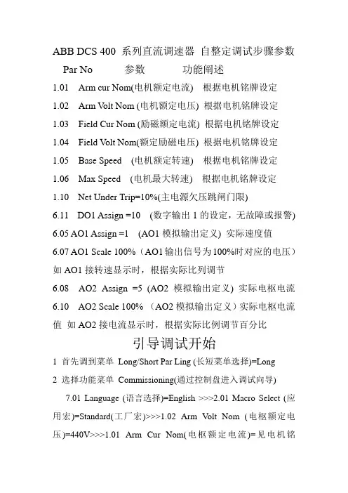
ABB DCS 400 系列直流调速器自整定调试步骤参数Par No 参数功能阐述1.01Arm cur Nom(电机额定电流) 根据电机铭牌设定1.02Arm V olt Nom (电机额定电压) 根据电机铭牌设定1.03Field Cur Nom (励磁额定电流) 根据电机铭牌设定1.04Field V olt Nom(额定励磁电压) 根据电机铭牌设定1.05Base Speed (电机额定转速) 根据电机铭牌设定1.06Max Speed (电机最大转速) 根据电机铭牌设定1.10Net Under Trip=10%(主电源欠压跳闸门限)6.11DO1 Assign =10 (数字输出1的设定,无故障或报警) 6.05 AO1 Assign =1 (AO1模拟输出定义) 实际速度值6.07 AO1 Scale 100% (AO1输出信号为100%时对应的电压)如AO1接转速显示时,根据实际比列调节6.08 AO2 Assign =5 (AO2模拟输出定义) 实际电枢电流6.10 AO2 Scale 100% (AO2模拟输出定义)实际电枢电流值如AO2接电流显示时,根据实际比例调节百分比引导调试开始1 首先调到菜单Long/Short Par Ling (长短菜单选择)=Long2 选择功能菜单Commissioning(通过控制盘进入调试向导)7.01 Language (语言选择)=English >>>2.01 Macro Select (应用宏)=Standard(工厂宏)>>>1.02 Arm V olt Nom (电枢额定电压)=440V>>>1.01 Arm Cur Nom(电枢额定电流)=见电机铭牌>>>1.04 Field V olt Nom(磁场额定电压)=见电机铭牌>>>1.03 Field Cur Nom(磁场额定电流)=见电机铭牌>>>1.05 Base Speed (电机额定转速)=见电机铭牌>>>Field weakening(是否弱磁)=Yes>>>1.06 Max Speed直接按确定>>>4.06 Field Trip 直接按确定>>>2.03 Stop Ramp 直接按确定>>> 5.09 Accel Ramp 直接按确定>>> 2.04 Eme Stop Mode 直接按确定>>> Field Auto tuning (励磁电流调节器自动整定)=Yes>>> Start Drive (按启动键,使电机磁场上电) 然后屏幕显示Please wait .稍等片刻后,屏幕出现Press Enter(请按确认键)。
Chapter 14 CommunicationsTA BLE OF CONTENTSChapter 14 Communications (1)14.1 General Information (2)14.1.1 Objectives (2)14.1.2 Legend (2)14.2 MMS Communication between Applications (3)14.2.1 General (3)14.2.2 MMS Communication Principle (3)14.2.3 Access variables (4)14.2.4 MMS Variable Rules (5)14.2.5 Variable Attributes (5)14.3 Reading Data from an Access Variable (6)14.3.1 Performance Considerations and Structured Access Variables (7)14.4 Set up an MMS Communication (8)14.4.1 How to Configure the Access Data Type (8)14.4.2 How to Define the Access Variable (10)14.4.3 How to Read Access Variables from Another Application (11)14.4.4 How to Extend Parameters (13)14.5 Other Function Blocks in the MMS CommLib (15)14.5.1 SIL2 certified function blocks (15)14.6 Communication to Other Devices (17)14.6.1 Communication Libraries (17)14.6.2 Hardware Configuration (18)14.6.3 Software Configuration (18)14.6.4 Address Syntax (20)14.7 How to Configure a Serial Communication Channel (21)14.7.1 SerialConnect (21)14.7.2 SerialListen (22)14.1 General Information14.1.1 ObjectivesOn completion of this chapter you will be able to:∙Describe the principle of MMS communication∙Create and define access variables∙Configure communication between controllers∙Explain the use of the different MMS blocks14.1.2 Legend< > Indicates a key name.| Indicates when you go from one menu to a sub-menu.Bold Indicates a menu name or an option in a menu, or file structures“ “Indicates dialog box buttons, tabs, instructions etc.Indicates start/explanation of student activity14.2 MMS Communication between Applications14.2.1 GeneralMMS stands for M anufacturing M essage S pecification. It is the protocol used tocommunicate on the control network between applications and also to the connectivityserver for the 800xA Aspect System.MMS supports transfer of simple and structured variables, program download andalarm handling. MMS is also used to define and make data available as Accessvariables.Generally the MMS communication between AC800M controllers should be limited ifpossible because it will use the controller‟s CPU capacity.14.2.2 MMS Communication PrincipleMMS communication handles communication between applications within oneAC800M controller and between applications allocated to two controllers.The applications may exist in the same controller:Or in different controllers on the control network:Remember that in Control Builder Professional one application does not necessarilycorrespond to one control system. It is possible to execute two applications within thesame controller. Even in this case though, we need to use MMS communication withAccess Variables if we want exchange data between the two applications.NOTE!The MMS communication should be limited and not beused for a lot of data.For instance: don’t write an application in one controller and use the IOsof another controller for this application.14.2.3 Access variablesFor communication between two Applications, Access variables are defined. An Access variable is a variable that is shared on the network.By sharing a local (or global) variable as an Access variable, it can be picked up byany system on the network, as long as the two systems in question share a common protocol, such as MMS, COMLI etc.Access Variables are defined in the Controller Hardware part of the Project Explorer:Access variables are defined in a particular controller. There may be many Access variables defined. Such variables are mapped into variables existing in the applications running in that controller. This mapping is done in the Access Variable Editor.The variable in the application which is mapped can be any variable existing anywhere in the whole application:∙ Variable in a program or Control Module ∙ Variable (global or local) in the application14.2.4 MMS Variable RulesMMS variables can only be accessed by their name which is a string. The namingrules are defined in MMS rather than as part of control builder, therefore there aresome differences in these rules compared to the standard naming rules for variables inprograms etc.∙An MMS access variable name can be up to 32 characters long and contain letters,digits and the characters dollar ($) and underscore( _ ).∙No spaces are permitted in the name of an MMS variable∙MMS variable names are case sensitive, i.e <TANK4> is not the same variable as<tank4>.∙The access variable name cannot begin with a digit or the dollar ($) character.∙The access variable may be mapped to any type of simple variable or (moreimportantly) to any type of structured variable.∙ A structured variable can have mixed data type components14.2.5 Variable AttributesBy default Access variables are Read/Write. If you want to make the variable ReadOnly then set the attribute in the Access variable table to …ReadWrite‟If the attribute field is left blank then the variable will be Read and Write.14.3 Reading Data from an Access VariableAccess variables are declared in the controller that acts as a server. The Accessvariable is in itself a reference to a variable in an application. This application acts asthe server application for the Access variable.The client application has to be configured with at least one Connect function blockand one Read or Write function block addressing the Access variable.In the above diagram an access variable has been defined and mapped to a variable inthe application called Application1.Now the objective is to read the values stored in it from Application2. This is donewith Function Blocks instances placed in a program in Application2.A minimum of two function blocks are required.∙Connect Function BlockThe purpose of this function block is to make the connection to the controllerwhich holds the access variable (referred to as the Remote System or Partner)∙Read Function BlockThe Read function block reads the values of the Access variable in the remotecontroller and transfers them into a local variable (Control Builder variable) in theapplication that is reading (Application2 above)NOTE!When using Function Designer, the Access variables andthe MMS communication are generated automatically!14.3.1 Performance Considerations and Structured Access VariablesEach and every read or write operation from/to an access variable requires atransmission across the network. Therefore it makes sense to pack as much data intothe Access variable as possible.It is possible to define Access variables for each and every simple variable in theapplication and then to access them individually. But this is not recommended becauseit results in many telegrams on the network.NOTE!It is far better to create a structured data typespecifically for the purpose.Such a structured data type can have many components and may be accessed in onetransaction:For MMS there is a limit of 1 Kbyte of data per telegram. This means that severalhundred real values may be packed into a structured variable and accessed in one…lump‟.In the accessing system the data in the structured variable may then be extracted bycode block looking at the components of the variable.14.4 Set up an MMS CommunicationIn this section we will show how an application can read data from another using anAccess variable.…Application1‟ will contain data that is to be made available to others. …Application2‟will read the data cyclically.To establish the link three stages are required:1.Define a structured data type to hold the data. Create a variable of this type inApplication1 and write the values into the components from code in Application12.Define an access variable and set the path to the variable containing the data inApplication1.3.In Application2 create an instance of the Connect function block type and anotherof (say) the MMSReadCyclic function block type. Configure these to read theAccess variable at the controller in which Application1 is executing and totransfer the values into a local variable in Application2.14.4.1 How to Configure the Access Data TypeThe data type should be defined in a project library which is connected to bothapplications. This is so that each application can declare a variable of this type. Theoriginal variable (in Application1) must have the same structure as the final variable(in Application2) so that the data matches component for component.The data type is structured to contain any combination of variables of any type. Thechoice of structure depends on the data to be made available.Imagine that application 1 has the new data type …MMS_Data_App1_Type‟ with thefollowing structure:MMS_Data_App1_TypeBool1 BooleanBool2 BooleanInteger1 DintInteger2 DintReal1 RealReal2 RealString1 StringString2 String1.Create a new data type in a project library2.Declare a variable in Application1of this type. Call it, say, …App1_Data‟.It is convenient to declare this as a Global variable in the application, because then it is available to all control module instances and all programs in the application.These objects may then write into the components.14.4.2 How to Define the Access Variable1.In the controller in which this application or program will run double-click on“Access Variables” and select then the tab “MMS”.2.Declare an Access variable whose name is, say, …Controller1_App1_Data‟.NOTE!It is useful to name the controller and the application towhich the data ref ers in the name you choose.3.Set up the path from YourNameData to the variable in the application or programusing the path button as shown below:Be very clear in your mind about what is going on here.In the above example, the access variable is called Controller1_App1_Data– it isthis variable that is …made available‟ on the network.The variable in the application or program is called App1_Data – your applicationprogram will write values into the components of this variable which is of typeMMS_Data_App1_Type.The path column links the variable in the application or program to the accessvariable.NOTE!Refer to the diagram at the beginning of this chapter toensure you have the right idea.If the values in the components of the variable …App1_Data‟ change, then the values inthe components of the access variable called …Controller1_App1_Data‟ will alsochange.Similarly if a remote system writes to the values in …Controller1_App1_Data‟ then thecomponents of …App1_Data‟ in the application or program will also change.14.4.3 How to Read Access Variables from Another ApplicationNow we will see how Application2 can read the Access variable…Controller1_App1_Data‟. This is a first simple example which reads the datacyclically (we shall discuss other possibilities later).Two function blocks are needed, both from MMSCommLib:∙MMSConnect∙MSReadCyclic1.Create an instance of each type in a Program (or a Control Module) inApplication2.2.Declare the following (minimum) set of variables in the program.Note that the variables AccessVariableName and PartnerAddress have been giveninitial values (see below).3.Connect these variables as shown below:MMSConnectThe <ConnectID> variable is connected between the Connect and the ReadCyc function Block. It passes signals which co-ordinate the activity of the two.The MMSConnect needs to know which controller to connect to (you need to know someones mobil number in order to connect to them). This information is given by the variable <PartnerAddress>.It is always a string data type and it has an initial value equal to the IP address of the controller where the access variable required has been defined.MMSReadCycThe <AccessVarName> variable is a string data type with an initial value equal to the name of the Access variable defined at the remote controller(Controller1_App1_Data‟).NOTE!MMS variable names are case sensitiveThe <App1Data> variable is the local variable in this program into which the remote dat will be placed. The components of this variable get written with the data that is in the components of …App1_Data‟ in Application1.Communication checkIt is a good idea to check first whether the communication is okay. Check the status of the MMSConnect block and use that as an input for the <Enable> parameter on the MMSReacCyc block.14.4.4 How to Extend ParametersSome function block types have extensible parameters. This means that the number ofinput/output parameters is variable and may be specified when you declare thefunction block in the function block tab.By default the editor automatically inserts [1] when you specify a function block typewith extensible parameters. The programmer changes the number within the bracketsto the required number of parameters.You can change the number of such parameters at creation time as shown below:1.In the InsertFunction/Function Block Dialogue set the size to the number yourequire.2.Alternatively, change the number in square brackets in the function blockdeclaration pane.3. A function block with three pairs of VarName and Rd parameters is generated.This read cyclic block can now read three access variables from the same remote system.NOTE!In Function Block Diagram (FBD) and Ladder Diagram(LD), a maximum of 32 extensible parameters perfunction block can be shown.14.5 Other Function Blocks in the MMS CommLibMMSReadThis module performs an event driven read of an access variable from the remotesystem. This allows a programmer to trigger a read operation on from code. It isconnected in a similar way to the MMSReadCyc.MMSWriteThis module writes values into an access variable at a remote system. It is event drivenon the rising edge of the …Req‟ parameter.Note tat if the Access variable at the remote system has been given the attribute…ReadOnly‟, this module will fail!MMSWriteDTThis module writes a Date and Time an AccessVariable in the remote system. TheAccess variable should be linked to a single Date_And_Time type variable. Note thatthis block does not write to the actual system time in the remote system. If you wish todo that, then addition code is required at the destination system.MMSDefAccVarThis module allows the definition of an access variable from application code. Inmany circumstances you wish to create access variables in a controller at run time. 14.5.1 SIL2 certified function blocksFor SIL2 certification greater reliability is required, none of the above function blocktypes are suitable for SIL2 applications.A range of SIL2 function block types are defined in the MMSCommLib which aresuitable. These are:14.6 Communication to Other DevicesIn this part we look at communication to other devices which may be on proprietarybuses or via a serial link using RS232 or RS485.Such devices might be instruments, other controllers from other manufacturers or anyother devices which have communication protocols defined. It is also possible to havea raw serial link and to build function blocks to interpret from devices which use nospecific protocol, printers, bar code readers etc.The AC800M has one single RS232 port available on the CPU itself, this is COM3and has an RJ45 connection point. If you only need one serial link then this can beuseful.If more RS232 ports are needed then the Communication Interface module CI853provides two ports per module. Several such modules could be mounted on the CEXbus of the controller.For other devices there may be specific Communication Interface modules providedfor installation on the CEX bus.14.6.1 Communication LibrariesThe principle of Connect and Read and Write blocks applies to both access variableand Serial communication to other devices.In the libraries described in chapter “Libraries” you will find Connect and Read/Writeblocks for many well known protocols and devices.A series of communication libraries contain the function block types used to makeconnections either to devices connected over a serial link using an RS232 port on thecontroller or a communication interface module.14.6.2 Hardware ConfigurationThe channel may be defined at COM3 as follows:1.Mark COM3 in the Hardware Tree and click right to select “New Unit”2.Select the required Protocol from the list.3.Having determined the protocol for the port, click right and select “Editor” toconfigure protocol specific settings.14.6.3 Software Configuration1.Load the appropriate library for the protocol required.2.Connect the library to the application that will contain the function blocks for theConnect and Read/Write operations.3.Insert the required function blocks into the program in a similar way to that forAccess variable communication.One connect per remote system followed by read and write blocks as required.Connect function blockThe Connect block will require a channel address. This is the position of the comms channel in the hardware. It is in the form <HardwareUnitNumber.Channel>.The Modbus channel above is designated …0.3‟ because it is on hardware unit no 0 and position 3 (this is labelled COM3 on the physical CPU casing).Here are some further examples:Read/Write BlocksThe Blocks will require a remote system address referred to as the partner. This is usually the numeric Slave address expressed as a string variable (not an integer). They will also require addresses for the data in the remote system.Again these are string type variables, but the format will depend on the memory organization and acceptable identifiers defined in the remote system.14.6.4 Address SyntaxYou may need to refer to the manufacturer‟s l iterature for the addressing syntax.COMLIAddress Bits in Memory with ‘X%nnnn’ wher nnnn is the octal address of the bitmemory location.Address Register in memory with ‘%Rnnnn’ where nnnn is the decimal registernumber.COMLI can read or write up to 512 Bits and up to 32 Registers in one telegram.Always read or write in Multiples of 8 bits. Do not address across Octade boundaries.If you‟re reading lots of bits then its best that they are contiguous to avoid severaltelegrams being generated.Modbus%IX8#100 Bit input memory localation octal format%QX8#100 Bit Output memory location octal format%IX10#64 (input) Bit input memory localation decimal format%QX10#64 (output) Bit Output memory location decimal format%IX16#40 (input) Bit Input memory location Hexadecimal format%QX16#40 (output) Bit Output memory location hexadecimal format%MW8#55 Memory Word (Register) Octal format%IW8#55 Input Word Octal format%QW8#5 Output Word Octal format%MW10#45 Memory Word Decimal format%IW10#45 Input Word Decimal format%QW10#45 Output Word Decimal format%MW16#2D Memory Word Hexadecimal format%IW16#2D Input Word Hexadecimal format%QW16#2D Output Word Hexadecimal formatSystem 800xA training 21 / 2214.7 How to Configure a Serial Communication ChannelIt is possible to communicate with other equipment using an open serial channel on the controller. The following Function Blocks are defined in the Control Builder: ∙ SerialConnect Use the SerialConnect function block to open and close a defined serialcommunication channel.∙ SerialListen Use the SerialListen function block for listening, that is receiving a string sentfrom a sending device.∙ SerialListenReply Use the SerialListenReply function block for listening, that is receiving a stringsent from a sending device to the <Rd> parameter. When data is received, a reply of a string type variable is sent to the sending device.∙ SerialSetup Use the SerialSetup function block to change settings for checksum calculationand echo handling while sending and receiving strings with any of the following function blocks: SerialWriteWait, SerialListenReply, SerialWrite and SerialListen. ∙ SerialWrite The SerialWrite function block writes a string to a receiving device.∙ SerialWriteWait Use the SerialWriteWait function block to send a string type variable via the <Sd>parameter to a receiving device. The function block waits for a reply from the receiving device which will be received through the parameter <Rd>.14.7.1 SerialConnectTo establish connection, activate the Enable parameter (setting it to True) and specify the physical channel with the Channel parameter. A reference to the connection is put in the Id parameter to be used by other function blocks communicating via the same connection.148153598.doc22 / 2214.7.2 SerialListenUse the SerialListen function block for listening, that is receiving a string sent from asending device.∙EndChar is used to set which character is to define the end of a message. Thesetting of EndChar only applies when the MsgLength parameter is set to 0.∙The valid range of EndChar is 0 - 255, where 0 = none and 13 = CR (ASCII).∙If MsgLength is set to a value greater than 0, the value defines the length of themessage. If MsgLength is set to 0, the message can be of any length. The endcharacter defined by the EndChar parameter indicates the end of the message.∙NoOfTrailChar sets the number of characters after the end character. Thisparameter is ignored if Checksum validation is set using the function blockSerialSetup.。
ABBDCS400直流调速器调试(工程师培训)ABB DCS 400 系列直流调速器自整定调试步骤参数Par No 参数功能阐述1.01Arm cur Nom(电机额定电流) 根据电机铭牌设定1.02Arm V olt Nom (电机额定电压) 根据电机铭牌设定1.03Field Cur Nom (励磁额定电流) 根据电机铭牌设定1.04Field V olt Nom(额定励磁电压) 根据电机铭牌设定1.05Base Speed (电机额定转速) 根据电机铭牌设定1.06Max Speed (电机最大转速) 根据电机铭牌设定1.10Net Under Trip=10%(主电源欠压跳闸门限)6.11DO1 Assign =10 (数字输出1的设定,无故障或报警) 6.05 AO1 Assign =1 (AO1模拟输出定义) 实际速度值6.07 AO1 Scale 100% (AO1输出信号为100%时对应的电压)如AO1接转速显示时,根据实际比列调节6.08 AO2 Assign =5 (AO2模拟输出定义) 实际电枢电流6.10 AO2 Scale 100% (AO2模拟输出定义)实际电枢电流值如AO2接电流显示时,根据实际比例调节百分比引导调试开始1 首先调到菜单Long/Short Par Ling (长短菜单选择)=Long2 选择功能菜单Commissioning(通过控制盘进入调试向导)7.01 Language (语言选择)=English >>>2.01 Macro Select (应用宏)=Standard(工厂宏)>>>1.02 Arm V olt Nom (电枢额定电压)=440V>>>1.01 Arm Cur Nom(电枢额定电流)=见电机铭牌>>>1.04 Field V olt Nom(磁场额定电压)=见电机铭牌>>>1.03 Field Cur Nom(磁场额定电流)=见电机铭牌>>>1.05 Base Speed (电机额定转速)=见电机铭牌>>>Field weakening(是否弱磁)=Yes>>>1.06 Max Speed直接按确定>>>4.06 Field Trip 直接按确定>>>2.03 Stop Ramp 直接按确定>>> 5.09 Accel Ramp 直接按确定>>> 2.04 Eme Stop Mode 直接按确定>>> Field Autotuning (励磁电流调节器自动整定)=Yes>>> Start Drive (按启动键,使电机磁场上电) 然后屏幕显示Please wait .稍等片刻后,屏幕出现Press Enter(请按确认键)。
DCS操作培训资料全不饱和树脂DCS生产操作工手册(初稿)一、阀门1.认识阀门:我们使用的阀门有切断阀、调节球阀、调节油阀(薄膜阀)。
这主要分成两部分,一是DCS画面显示阀门状况,二是现场阀门状况。
DCS中,切断阀为长方形阀头,阀头只有两种颜色,红和绿.。
所有切断阀阀身形状均为一致,为两个对三角和一个方块组成,方块是阀门开关命令按钮,阀门上面位置标注位号,切断阀阀身有三种颜色,红、绿、黄色;。
调节阀阀头为半圆形,并且在阀头位置上下摆布绿、橙黄两个数字,绿色为阀门开度按钮,橙黄色是回讯开度;现场中,是切断阀的,有一个显示有OPEN和CLOSED两种状态的阀头,调节阀则有一个方形的标有0~100刻度的盒子并带有指针。
0~100就是表示此阀门的开度从0%~100%,0时表示阀门开度为0,阀门没有打开,100时,表示阀门全开。
2.操作方式:开关切断阀时,只需点击阀头,在弹出的对话框中,选择开阀(绿色)或关阀(红色)。
开关调节阀时,点击调节阀头位置摆布的绿色数字,在弹出的对话框中输入所需要的阀门开度,回车即可。
3.状态显示:正常关闭切断阀时,DCS中状态是阀头阀身均为红色,现场显示CLOSED;正常开启切断门时,阀头和阀身均为绿色,现场显示为OPEN;当阀头显示一种颜色时,DCS中出现阀身与阀头颜色不一致均为错误,其中,当阀身出现黄色时,则为故障信号,均需立即到现场查看:现场要根据DCS中操作的意向,检查现场显示状态,判断错误情况,并立即通知机电维修同时上报班长、车间主任。
调节阀正常使用的情况下,阀头位置摆布的数字,红、绿误差不得超过3%,现场指针也应对应指示。
超出规定误差必须通知机电维修,并上报。
4.油阀门的操作注意事项:由于油路都是密闭循环管路,加之冷热的收缩膨胀等因素,用油设备任何时候都必须有敞口。
正常使用时,管路处于循环状态,不使用时,必须让一组出油阀处于打开状态。
开启热油加热时,一定要掌握速度,不能过快,阀门开度不能一次性过大,只能逐步加大,否则会导致油温迅速下降,影响升温速度。