boiler designs for the AD700 Power Plant
- 格式:pdf
- 大小:1.72 MB
- 文档页数:29
百思特炒冰机中英文说明书本公司专业设计开发,生产销售各种炒冰机。
以市场需求为基础,凭借“诚心是我们的生命”的宗旨。
不断提高技术水平和企业综合实力。
本着以人性化,以技术为力量,以市场为前景,以质量求生存的方针,不断引进国外先进的技术和生产工艺。
从而开发出一系列技术先进,性能稳定,外观新型美观大方的炒冰机。
1.炒冰机采用先进的进口压缩机,节能,噪音小,寿命长,使用更方便。
2.炒冰机制冷速度快,制作方便,在短时间内可制作多杯冰爽可口的饮料。
3.多种品味选择;可根据顾客需要的不同品味制作不同冰品,可将水果用搅拌器打碎成汁炒入冰中,或将水果切成不同形状炒入冰中,做成纯天然的水果饮料。
味道鲜美,营养丰富,冰爽可口。
4.提供优质完善的售后服务,背后技术支援以及提供配方和原材料。
百思特炒冰机打破目前传统的饮料制作方法,可将纯净水,无菌水等加入配制好的各种饮料配方及水果制作成冰饮制品。
其特点如下:百思特炒冰机采用先进的制冷技术,其流线型结构设计。
坚固耐用,使用方便。
百思特炒冰机外壳采用不锈钢制品,经久耐用,不生锈,防水,防晒。
百思特炒冰机机身喷涂逼真的图案,生动鲜明,使整机显得美观大方。
百思特炒冰机采用名牌大功率压缩机,制冷速度快,性能稳定。
百思特炒冰机在制作炒冰时无污染,环保,对人体无任何伤害。
1.使用前保证炒冰机身放置平稳。
2.将炒冰机接通电源,电压为交流220v.3.打开炒冰机电源总开关,使用前将机器预冷1-2分钟。
4.将调配好的纯净水或凉开水量杯选量后倒入锅内5.待锅底结冰后,用锅铲顺锅底轻轻向前推炒,反复推炒将饮料搅均炒匀到冰沙状后即可铲出至杯中食用。
6.因炒冰机采用大功率压缩机,制冷速度快。
所以在制作炒冰时饮料会因过冻而贴紧锅底,利用炒制,此时应打开除霜开/关2-5秒钟直到容易铲炒时再关掉开关。
注:以上第四项内容,由于制作时炒冰等级不同,价格也不同,所以配料也有所不同。
建议分以下三个等级:一等级:调配好的纯净水或凉开水,炒制时将使用搅拌器打碎成水果汁(各种水果任顾客挑选)炒入冰中。

Models:EP-1-2828, EB-1-2828EP-2-2828, EB-2-2828Bakers Pride Oven Company, LLC is a wholly owned subsidiary of Standex International Corporation.All gas operated Bakers Pride ® countertop deck ovens are intended for use with the type of gas specified on the rating plate and for installation will be in accordance with National Fuel Gas Code ANSI Z223.1 (latest edition).Please retain this manual for future references.This equipment is design engineered for commercial use only.BAKERS PRIDE OVEN COMPANY, LLC.1307 N. Watters Rd., Suite 180Allen, TX 75013Phone: 800.527.2100 | Fax: 914.576.0605 | TABLE OF CONTENTSDIMENSIONS & SPECIFICATIONS 1INSTALLATI N 3COUNTERTOP INSTALLATION 3FLOOR INSTALLATION 4OPTIONAL BASE FEATURE 4DOUBLE STACKED OVENS 5ELECTRICAL CONNECTIONS 5EXPLANATION OF CONTROLS 6USAGE RECOMMENDATIONS 7TR UBLESH TING 7CLEANING 8EXTERIOR CLEANING 8INTERIOR CLEANING 8MAINTENANCE 8REPLACEMENT PARTS 8WIRING DIAGRAMS 8PARTS LIST & EXPLODED VIEW 9WIRING DIAGRAMS 11WARRANTY 16DIMENSIONS & SPECIFICATIONSPeriodic inspections by your dealer or a qualified service agent is recommended. When corresponding with the factory or your service agreement regarding service problems or replacement parts, be sure to refer to the oven by the correct model number (including the prefix and suffix letters and numbers) and the warranty serial number. The rating plate affixed to the oven contains this information.IMPORTANT FOR FUTURE REFERENCEPlease complete this information and retain this manual for the life of the equipment. For Warranty Service and/or Parts, this information is required.Model Number Serial NumberDate PurchasedDIMENSIONS & SPECIFICATIONSDimensionsINSTALLATION INSTRUCTIONSIt is the responsibility of the purchaser to ensure the oven is properly installed in a manner that meets all applicable codes. In the absence of local codes refer to applicable national codes. In the case of any discrepancy between this document and any local codes it is recommended you consult your local inspector.Users are cautioned that maintenance and repairs shall be performed by authorized service agents or licensed professionals only. Bakers Pride will have no obligation with respect to products that are not properly installed, adjusted, operated or maintained.Countertop InstallationThe oven may be installed directly on a counter or stand manufactured of non-flammable materials. The oven must be installed on a surface that is at least as large as the outer dimensions of the oven. The oven must be installed with adequate clearance to combustible and non-combustible walls. If legs are not used the oven must be sealed to countertop with an NSF approvedsealant.Minimum Operating ClearancesClearances to combustible surface is 1 inch [25 mm]. It is recommended the oven he at least 1 inch from any adjacent cooking appliance. Each oven shall be installed with respect to building construction and other equipment to permit access to the oven. Such clearance may be necessary for servicing and cleaning. Bakes Pride ® recommends the mounting surface for a single oven be approximately 26 inches [660 mm] from the floor so the oven decks are at a convenient working height.NOTE: Refer to illustration for all three leg configurations A. Countertop – Short Legs – 4”B. Floor Model -30” C. Floor/Double Stack -16”INSTALLATION INSTRUCTIONSCountertop Legs1. Turn the oven over onto its left side so you caneasily reach the bolt mounting locations base.2. Using the four corner most holes in the bottom ofthe oven insert and tighten the four countertop legs.3. Carefully turn the oven upright. Insure the twolegs that touch the floor first when you raise theoven are blocked so they do not slip away.Floor Installation1. At the floor end of each leg install the bullet footinsert or caster as required. The fit of the insert to the leg is intended to be snug, you should expect to tap them lightly in place with a mallet or rubber hammer. Using your fingers screw the ends of the bullet feet into the leg clockwise until they areat their shortest length. Or Casters mount to thebottom of the caster plate with four each: 3/8-16 bolts inserted into a split ring lock washer and flat washer.2. Turn the oven over onto its left side so you can easilyreach the bolt mounting locations in the base.3. The three holes in the top of each leg will matchthe bolt locations at each corner of the oven base.4. You will need three 3/8-16 hex head bolts andthree 3/8” flat washers to mount each leg. Alignthe leg to one of the matching bolt holes on thebase and inset a bolt and washer. Install the other bolts and finger tighten into place before using awrench to fully tighten them all.5. Be sure to tighten all bolts for each leg. Wheninstalling casters, make sure the two casters with brakes are installed at the front of the oven andthe restraining plate is inserted between the right rear leg and the oven base as shown.6. Carefully stand up the oven. Insure the two legs/casters that touch the floor first when you raise the oven are blocked and chocked so they do not slip away.7. Attach the Warning label for the restraining deviceon the face of one of the front legs as shown.8. Provide a suitable restraining chain or cable tosecurely tether the appliance to the buildingstructure. The restraining chain or cable should be of such length, that it will stop movement of theappliance before there is any strain on the powersupply cable.Optional Open Base Feature:1. Install bottom shelf and rack guide brackets wheninstalling legs -while oven is on it’s side. Refer toleg instructions in Installation/Operation Manual.2. Attach two rack support brackets to base of ovenwith three screws each bracket.3. Install two legs to lower (left) side of oven. Alignand attach bottom shelf to these legs with a boltand locking nut -One each in the front and back.4.Attach last two legs.INSALLATION INSTRUCTIONS5. Attach bottom shelf to remaining two legs with twobolts and locking nuts - One each in the front and back.6. When the oven is stood up, before moving it toit’s final location, install four remaining bolts and locking nuts to the legs -Two on left side, two on right side. Tighten all.7. Install two rack guides. Align the bottom pegs toholes in the bottom shelf. Align top hooks to cut- outs in upper support bracket. Lower into position.8. Align oven racks (order separately) to the shelfheights desired and slide into place.Electrical ConnectionsDouble Stacked OvensYour EP/EB-1-2828 or EP/EB-2-2828 may be stacked two ovens on top of one another. In order to ensure the ovens do not slide or separate, there is a stacking bracket kit required for installation at the rear of the ovens. Two brackets are installed, one at each end of the oven securing the upper oven to the bottom oven. Refer to the adjacent illustration.1. Installation must be performed by licensedelectrician.2. A separate electrical connection to the mains mustbe provided for each oven. 3. An all pole disconnect must be provided by theinstaller.4. Connection to the electrical service must begrounded in accordance with local codes. In the absence of local codes refer to the National Electric Code, ANSI/NFPA 70 or the Canadian Electric Code, CSAC22.2 as applicable.5. Only bare copper conductors with a minimuminsulation temperature rating of 90°C to be used.6. The installer must supply a properly sized strainrelief bushing for the mains connection that meets 7. The oven shall be installed using flexible conduit.8. The restraint cord must be securely attached tothe rear of the oven and to the building structure to prevent transmitting unnecessary stress to the flexible conduit.INSTALLATION INSTRUCTIONSExplanation Of ControlsThe oven has a main power switch at the bottom portion of the control panel. This switch must be on for the oven to operate. When switched to the ON position the lamps in each cavity light.Each cavity has separate temperature controls. The thermostat dial may be adjusted from 200°F (100ºC) to 700°F (370ºC).Heat Selector Switches:To better control the ratio of Top and Bottom Heat, these ovens have two heat selector switches, one controlling the Top Heat, the other controlling the Bottom Heat. Each allows a setting from #1 (low = 20% on/80% off) through #9 (80% on/20% off) to #10 (high = 100% on). In order to maximize the potential of the oven and to get maximum power, both heat selector switches should be set to #10 (high). This will be the best setting most of the time for most of the products. However, if, after some experimenting, one of the two proves to be too hot, only that one should be reduced while the other one stays on high. There is no need to reduce both at the same time. If less heat is required, lower the thermostat setting.Each cavity has a timer that may be used when cooking product. The timer DOES NOT control the oven. Toset a cook time turn the dial clock-wise to the desired setting. The timer will count down until the time expires.A buzzer will sound continuously until the dial is turned to the “OFF” position slightly to the left of “0”.Ovens with Steam Option:Never activate the steam timer when the oven is cold, since the steam will immediately condense and turn to water.a) The steam timer can be adjusted from 1 to 60seconds and has been factory set for 3-5 seconds.To change this time, insert a small screw driverthrough the 1/4” diameter hole below the steamswitches and turn the timer shaft clock-wise toincrease or counter-clockwise to decrease thistime delay setting. b) Press both steam switches simultaneously. The redindicator lamp will illuminate, the solenoid coilwill be activated and the solenoid valve will openand allow steam to enter the baking chamberfor the duration of the selected time. After thatperiod, the power to the red indicator lamp andsolenoid coil will be cut off and the solenoid valve will shut down the flow of steam to the oven.Hook-UpControl Panel: E-1-2828Control Panel: E-2-2828INSTALLATION INSTRUCTIONSUsage Recomenations1. Pre-heat the oven thoroughly before use. Allow onehour and fifteen minutes for pre-heat. 2. Pre-heat ovens @ 75°F (24°C) BELOW desiredcook/bake temperature.3. Do not move baking location in the middle of abake, but spinning is okay. 4. Keep decks clean of flour, cheese, etc using a deck/scraper brush. 5. During idle periods, reduce heat by 75°F (24°C). 6. Minimize water content of products for faster cook/bake times. 7. For larger & thick products, reduce temperature &increase bake/cook time. 8. Cooking times and temperatures will vary dependingupon such factors as size of the load, temperature, mixture of products (particularly moisture) and density of products.9. Keep a record of the times, temperature and loadsizes you establish for various products. Once you have determined these, they will be similar for succeeding loads. 10. When practical, start cooking the lowesttemperature product first and gradually work up to the higher temperatures. 11. When loading the oven, work as quickly as possibleto prevent loss of heat. 12. Oven will continue to heat even though the timergoes off. Product should be removed from the oven as soon as possible to avoid overcooking. 13. When baking, weigh or measure the product in eachpan to assure even cooking. 14. Only bread and pizza may be placed directly on astone baking hearth.TroubleshootingThere are no user serviceable components behind the covers. Contact your service agent.OPERATING INSTRUCTIONSCleaningWhen the oven is new, operate it for at least one hourat a setting of at least 500°F (250ºC). Due to normal manufacturing processes, a small amount of steam and/ or smoke will exit the oven from moisture and oils on the oven components. Shut off and allow the oven to cool. After cooling wipe down the interior of the oven witha clean damp cloth. Brushing of the baking hearth is recommended.Exterior CleaningIt is recommended that a regular cleaning schedule be maintained to keep your oven operating and looking its best. Spills should be cleaned immediately.The oven should always be allowed to cool sufficiently before cleaning. Exterior surfaces should be wiped with a soft cloth and mild detergent. Stubborn stains may be cleaned with a light weight, non-metallic cleaning pad. Apply only light pressure and rub in the direction of the surface grain.The control panel surface is easily cleaned with a soft cloth and mild detergent. Do not use abrasives, solvent cleaners or metallic scouring pads on the control panel. They may scratch or damage the label surface.Never spray steam or water directly onto or into the oven. This could adversely affect the ceramic cooking hearth and/or electrical components.Interior CleaningInternal metallic surfaces should be allowed to cool before cleaning. Wipe interior surfaces with a wet cloth or light weight scouring pad.Food particles or spills that accumulate on the baking hearth may be brushed off with a normal oven brush. Stubborn spills should be heated to a maximum temperature for approximately one hour to burn the spill so it will crumble and easily brush out afterwards. Do not use oven cleaners, caustic solutions or mechanical means that may damage the interior of your oven.MaintenanceUsers are cautioned that maintenance and adjustments should only be performed by authorized service agents using Bakers Pride replacement parts.Minor periodic maintenance to your oven should provide many years of useful service to you. Any time the unit is serviced it is recommended all components be checked and their performance verified. At least once each year your oven should be inspected by a qualified service provider to insure your oven is operating at its peak performance.Replacement PartsEnclosed in this booklet are diagrams of likely replacement parts that may be required for normal maintenance. Specifications are subject to change without notice. Be sure to verify the current specification with your qualified service provider or Bakers Pride before ordering replacement parts.Wiring DiagramsThe current wiring diagram at the date of your oven’s manufacture was affixed to the unit for reference. Copies of the proper wiring diagrams effective on the date this booklet is printed are enclosed. Specifications are subject to change without notice. If there is any uncertainty or discrepancy between the wiring diagram and your oven refer to Bakers Pride Technical Service for clarification.OPERATING INSTRUCTIONS Exploded View & Parts ListOPERATING INSTRUCTIONSOPERATING INSTRUCTIONS Wiring DiagramsOPERATING INSTRUCTIONSOPERATING INSTRUCTIONSOPERATING INSTRUCTIONSOPERATING INSTRUCTIONSBAKERS PRIDE LIMITED WARRANTYWHAT IS COVERED This warranty covers defects in material and workmanship under normal use, and applies only to the original purchaser providing that:• The equipment has not been accidentally or intentionally damaged, altered or misused;• The equipment is properly installed, adjusted, operated and maintained in accordance with Nationaland local codes and in accordance with the installation instruction provided with the product;• The serial number rating plate affixed to the equipment has not been defaced or removed.WHO IS COVERED This warranty is extended to the original purchaser and applies only to equipment purchased for use in the U.S.A.COVERAGE PERIOD Cyclone Convection Ovens: BCO Models: One (1) Year limited parts and labor; (1) Year limited door warranty.GDCO Models: Two (2) Year limited parts and labor; (2) Year limited door warranty.CO11 Models: Two (2) Year limited parts and labor; (5) Year limited door warranty.All Other Products: One (1) Year limited parts and labor. Warranty period begins the date of dealer invoice to customeror ninety (90) days after shipment date from Bakers Pride - whichever comes first.WARRANTY This warranty covers on-site labor, parts and reasonable travel time and travel expenses of the authorized service COVERAGE Representative up to (100) miles, round trip, and (2) hours travel time. The purchaser, however, shall be responsible for all expenses related to travel, including time, mileage and shipping expenses on smaller counter models that may becarried into a Factory Authorized Service Center, including the following models: PX-14, PX-16, P18, P22S, P24S, PD-4,PDC, WS Series and BK-18.EXCEPTIONS All removable parts in Bakers Pride® cooking equipment, including but not limited to: Burners, Grates, Radiants, Stones and Valves, are covered for a period of SIX MONTHS. All Ceramic Baking Decks are covered for a period of THREEMONTHS. The installation of these replacement decks is the responsibility of the purchaser. The extended Cyclone doorwarranty years 3 through 5 is a parts only warranty and does not include labor, travel, mileage or any other charges.EXCLUSIONS• Negligence or acts of God,• Failures caused by erratic voltages or gas supplies,• Thermostat calibrations after (30) days fromequipment installation date,• Unauthorized repair by anyone other than a BakersPride Factory Authorized Service Center,• Air and Gas adjustments,• Damage in shipment,• Light bulbs,• Alteration, misuse or improper installation,• Glass doors and door adjustments,• Thermostats and safety valves with broken capillary tubes,• Fuses,• Char-broiler work decks and cutting boards,• Tightening of conveyor chains,• Adjustments to burner flames and cleaning of pilot burners,• Tightening of screws or fasteners,• Accessories — spatulas, forks, steak turners, grate lifters, oven brushes, scrapers, peels. etc.,• Freight — other than normal UPS charges,• Ordinary wear and tear.INSTALLATION Leveling and installation of decks as well as proper installation and check out of all new equipment —per appropriate installation and use materials — is the responsibility of the dealer or installer, not the manufacturer.REPLACEMENT PARTS Bakers Pride genuine Factory OEM parts receive a (90) day materials warranty effective from the date of installation by a Bakers Pride Factory Authorized Service Center.This Warranty is in lieu of all other warranties, expressed or implied, and all other obligations or liabilities on the manufacturer’s part. Bakers PrideIMPORTANT FOR FUTURE REFERENCEPlease complete this information and retain this manual for the life of the equipment. For Warranty Service and/or Parts, this information is required.Model Number Serial Number Date Purchased NOTESNOTESNOTES19Be sure to keep up with new product announcements and events on social media!。
海卓帕斯水处理器节能原理
海卓帕斯水处理器节能原理是什么,(郑州洛斯机电)作为海卓帕斯在中国区域的总代理,不仅为广大用户提供除垢、防垢的服务,更加有义务让大家了解其中的详细知识。
水垢导致能耗增加:
水垢的导热系数约为0.5-1W/mK,和换热器的铜管(370-420 W/mK)相比,导热系数相差300倍以上。
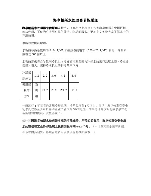
水垢的形成将会导致制冷机组内冷媒的冷凝温度与冷却水的出口温度之差(冷凝器端差)增大,使得冷水机组的制冷效率下降。
一般运行5年左右的常规冷却系统,端差温度在3℃以上。
所以,海卓帕斯交变电场水处理器至少可以帮助企业节省大约5%的电能。
如果再计算水垢造成水泵等设备所增加的能耗,就更客观了。
仅计算因海卓帕斯水处理器实现的节能减排,所节约的费用,海卓帕斯交变电场水处理器在工业冷却系统上投资回报周期6-12个月。
(不计算灭藻杀菌等价值,和节省的药剂费,各项管理费用以及设备的维护成本。
)。

3–37CDS-PRM001-EN • TRACE 700 User’s Manual Cooling and Heating Plants Purchased chilled water Purchased chilled waterPurchased chilled water is water that is typically chilled in aremote location and piped to individual buildings as a source ofcooling. A utility company will generally create the chilled waterin a central plant and charge the building owner and/or occupantsfor the water. There are several advantages to this type ofoperation: low first cost for the building owner, increased floorspace (because the chillers are not located in the building),possible lower environmental impacts due to the high efficiencyof large chillers, and so on. In addition, thermal storage can beused by the utility to allow generation of the chilled water atnight, when off-peak energy rates may be available, anddistribute it during the day, when needed by the customers.Application considerationI Purchased chilled water can offer lower first costs, but life cyclecosts may be higher.Related readingI Purchased chilled water, purchased district steam, andpurchased district hot water are all modeled similarly inTRACE 700. Refer to “Purchased district steam and purchaseddistrict hot water” on page 3–40.3–38Cooling and Heating PlantsTRACE 700 User’s Manual • CDS-PRM001-EN Purchased chilled water Sample scenarioIn this example, the building being modeled purchases chilledwater from a central chilled-water plant owned by the local utility.The building owner pays only for the chilled water and theelectrical use of the chilled-water pump. 1Start by clicking CreatePlants .2From the EquipmentCategory section on theleft side of the screen, clicka Water-Cooled Chiller and drag it over to thecooling plant.3–39CDS-PRM001-EN • TRACE 700 User’s Manual Cooling and Heating PlantsPurchased chilled water Note: The COP of purchased chilled water should be1.0 or less. A COP of 1 indicates that for every Btu ofcooling load, 1 Btu of purchased chilled water shouldbe consumed. Refer to “Frequently asked questions,”which begins on page 6-20, for additional details.3Click the cooling plant, clickEdit , and rename the plant.4Click the CoolingEquipment tab.5In the Equipment T ype list,click Purchased ChilledWater . It is alsorecommended to changethe Equipment Tag to amore appropriate name.6Because pumping energy isrequired in this scenario,input the pump type and the full-load energy rate.。
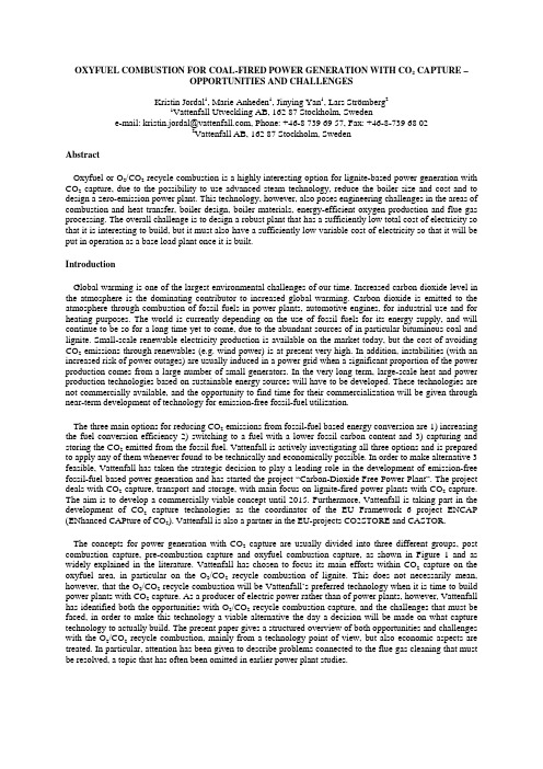
OXYFUEL COMBUSTION FOR COAL-FIRED POWER GENERATION WITH CO2 CAPTURE –OPPORTUNITIES AND CHALLENGESKristin Jordal1, Marie Anheden1, Jinying Yan1, Lars Strömberg21Vattenfall Utveckling AB, 162 87 Stockholm, Swedene-mail: kristin.jordal@, Phone: +46-8 739 69 57, Fax: +46-8-739 68 022Vattenfall AB, 162 87 Stockholm, SwedenAbstractOxyfuel or O2/CO2 recycle combustion is a highly interesting option for lignite-based power generation with CO2 capture, due to the possibility to use advanced steam technology, reduce the boiler size and cost and to design a zero-emission power plant. This technology, however, also poses engineering challenges in the areas of combustion and heat transfer, boiler design, boiler materials, energy-efficient oxygen production and flue gas processing. The overall challenge is to design a robust plant that has a sufficiently low total cost of electricity so that it is interesting to build, but it must also have a sufficiently low variable cost of electricity so that it will be put in operation as a base load plant once it is built.IntroductionGlobal warming is one of the largest environmental challenges of our time. Increased carbon dioxide level in the atmosphere is the dominating contributor to increased global warming. Carbon dioxide is emitted to the atmosphere through combustion of fossil fuels in power plants, automotive engines, for industrial use and for heating purposes. The world is currently depending on the use of fossil fuels for its energy supply, and will continue to be so for a long time yet to come, due to the abundant sources of in particular bituminous coal and lignite. Small-scale renewable electricity production is available on the market today, but the cost of avoiding CO2 emissions through renewables (e.g. wind power) is at present very high. In addition, instabilities (with an increased risk of power outages) are usually induced in a power grid when a significant proportion of the power production comes from a large number of small generators. In the very long term, large-scale heat and power production technologies based on sustainable energy sources will have to be developed. These technologies are not commercially available, and the opportunity to find time for their commercialization will be given through near-term development of technology for emission-free fossil-fuel utilization.The three main options for reducing CO2 emissions from fossil-fuel based energy conversion are 1) increasing the fuel conversion efficiency 2) switching to a fuel with a lower fossil carbon content and 3) capturing and storing the CO2 emitted from the fossil fuel. Vattenfall is actively investigating all three options and is prepared to apply any of them whenever found to be technically and economically possible. In order to make alternative 3 feasible, Vattenfall has taken the strategic decision to play a leading role in the development of emission-free fossil-fuel based power generation and has started the project “Carbon-Dioxide Free Power Plant”. The project deals with CO2 capture, transport and storage, with main focus on lignite-fired power plants with CO2 capture. The aim is to develop a commercially viable concept until 2015. Furthermore, Vattenfall is taking part in the development of CO2 capture technologies as the coordinator of the EU Framework 6 project ENCAP (ENhanced CAPture of CO2). Vattenfall is also a partner in the EU-projects CO2STORE and CASTOR.The concepts for power generation with CO2 capture are usually divided into three different groups, post combustion capture, pre-combustion capture and oxyfuel combustion capture, as shown in Figure 1 and as widely explained in the literature. Vattenfall has chosen to focus its main efforts within CO2 capture on the oxyfuel area, in particular on the O2/CO2 recycle combustion of lignite. This does not necessarily mean, however, that the O2/CO2 recycle combustion will be Vattenfall’s preferred technology when it is time to build power plants with CO2 capture. As a producer of electric power rather than of power plants, however, Vattenfall has identified both the opportunities with O2/CO2 recycle combustion capture, and the challenges that must be faced, in order to make this technology a viable alternative the day a decision will be made on what capture technology to actually build. The present paper gives a structured overview of both opportunities and challenges with the O2/CO2 recycle combustion, mainly from a technology point of view, but also economic aspects are treated. In particular, attention has been given to describe problems connected to the flue gas cleaning that must be resolved, a topic that has often been omitted in earlier power plant studies.Figure 1: The three basic concepts for power generation with CO2 captureO2/CO2 recycle combustion of ligniteThe principle of O2/CO2 recycle combustion of e.g. lignite in a pulverised fuel (PF) boiler can be seen in Figure 2. This kind of concept is related to the investigations that Vattenfall have been performing together with university partners so far and is described by Andersson et al. [1]. Instead of air, oxygen (95% purity or higher) is fed to the boiler, and a major part (70-80%) of the CO2-rich exhaust gas is recycled back to the boiler to control the combustion temperature. The remaining part of the flue gas, (consisting mainly of CO2 and water vapour and small quantities of Ar, N2, NO x, SO x and other constituents from air leakage and fuel) is cleaned, compressed and transported to storage or another suitable application, such as enhanced oil recovery (EOR). Provided that the gas is dry, it might be possible to sequester the sulphur with the CO2, although this is needs further investigation. The steam power cycle is of the standard type that can be found in conventional coal-fired steam power plants.Other studies of the power plant cycle with O2/CO2 recycle combustion can be found in [2-8]. The concept has attracted much interest for retrofit studies, both for coal [3-8] and for refinery fuel gas and heavy fuel oil [9,10], often in a context where the CO2 is intended for EOR [4,8-10]. Since power plants grow old and must be replaced, and with the advent of CO2 emission penalties, Vattenfall has its focus on O2/CO2 recycle combustion applied in new built power plants with advanced steam data where, unlike in the retrofit cases, an optimized process design based on best available technology can be made.Figure 2: The principle of O2/CO2 recycle combustion in a PF boiler.Opportunities with O2/CO2 recycle combustion of coalThe advantage of ongoing technology development for enhanced steam cycle efficiencyOne of the main opportunities with O2/CO2 recycle combustion of coal in new plants is that the steam cycle is able to take advantage of the ongoing development to increase steam cycle efficiency through the use of advanced steam technology and lignite drying. This advantage is shared with coal-fired post-combustion capture power plants. The development of advanced steam technology is not specifically linked to the CO2 capture field but more in general to the development of materials for extremely high pressures and temperatures, in combination with new boiler and turbine designs. During the 1990’s, power plants were built with very advanced steam data, such as Vattenfall’s lignite-fired units in Germany. Also several hard-coal fired and natural-gas fired plants have been built. Data for some plants are shown in Table 1. All data in Table 1except for the Lippendorf and Niederaussem are from [11].TABLE 1: DATA FOR SOME ADVANCED STEAM POWER PLANTS WITHOUT CO2 CAPTUREPower Station Capacity(MW) Steam parameters Fuel Efficiency(% LHV)CommissioningyearLippendorf 2*920 260bar/554°C/583°C Lignite 42.6 1999 Niederaussem K 950 275 bar/580°C/600°C Lignite 45.2 2002 Haramachi 2 1000 259 bar/604°C/602°C Bituminous1998 Nordjylland 3 400 290 bar/580°C/580°C/580°C Bituminous47 1998Skærbæk 3 400 290 bar/580°C/580°C/580°C NG 49 1997Avedøre 2 400 300 bar/580°C/600°C NG 49.7 2001For the ferritic materials used in the power plants in Table 1, the limit for the materials lies just above 600°C. Therefore, to go further in the development of steam data, the project AD700 has been initiated within the VGB organization. The project is in its second phase (2002-2005) and 50% financed by the EU and the Swiss government. Vattenfall is one of the 35 companies taking part. The technical objective of the project is development and demonstration of an economically viable, pulverised coal-fired power plant technology with a net efficiency of more than 50% (without CO2 capture) to be available shortly after 2010. The long-term target after year 2020 is net efficiency above 55% (without CO2 capture) based on steam temperatures above 800°C.AD700 covers new materials (Ni-based superalloys, austenitic steels), new materials manufacturing methods and new welding methods. Also boiler, turbine and other plant design issues will be addressed using these of these new and expensive materials. The project has recently decided on a large-scale test facility in the German Scholwen power plant.Raw lignite contains roughly 50% of moisture, meaning that a non-negligible amount of the heat released during combustion is employed to evaporate water. Future lignite-fired plants will probably include lignite drying by using low-temperature heat from the steam power cycle or the flue gas. This will boost the efficiency to levels comparable with bituminous coal. The additional investment cost for lignite drying is likely to be balanced by the increase in plant efficiency so that the specific investment cost in EUR/MWh e is unaffected.Reduced boiler heat losses and compact boiler designIn the air-fired boiler, large quantities of inert nitrogen is heated as a consequence of the combustion process, and although this nitrogen is cooled down again, it has a temperature above the ambient as the exhaust gas is released. The heat loss with the flue gas in a conventional air-fired boiler amounts to up to 10%. A significant part of this loss is the heat energy that leaves with the nitrogen in the flue gas. In the O2/CO2 recycle combustion boiler, there is no bulk nitrogen in the gas path, which in turn means that the heat losses with the flue gas can be significantly reduced. With the development of lignite drying through the use of low-temperature process heat, the inert flow through the boiler and thus the heat loss from the boiler will be further reduced.Many studies, both theoretical and experimental, that are related to the combustion of coal in an O2/CO2 atmosphere have been focusing on retrofit of existing PF boilers [3-8], where the boiler geometry is determined by the air-firing case, and where it has been a target for the O2/CO2 recycle case to obtain combustion conditions (flame temperature, heat transfer) as similar as possible to those of the air firing case. Therefore, the recirculation of CO2 from the boiler exhaust has been rather significant (typically around two thirds of the flue gas), in order to imitate the conditions during air firing, when nitrogen is present as an inert. Most likely, a firstgeneration of new oxyfuel boilers will also adapt this boiler design philosophy. With increasing knowledge and refined tools for modelling of combustion of lignite in an O2/CO2 atmosphere, it will be possible to refine the boiler design for the second and third generations of boilers. A major target will be to reduce the rate of, or even entirely avoid externally recycled flue gas. To maintain the flame temperature within acceptable limits, internal recycling of flue gas inside the boiler can be used. This will reduce the size of the boiler significantly, which means that the efficiency loss due to thermal radiation to the environment will be reduced (this loss is already today quite small though, around 1% of the fuel thermal energy), and also reduce the electric power requirement for the flue gas recirculation fans. A significant reduction of the boiler size will also lead to a reduction in boiler investment cost, since the cost of the boiler is more or less proportional to the weight of the boiler parts.Almost pure oxygen will be available for the combustion process in the boiler. This means that it will be possible to control and optimize the combustion process through the injection of oxygen in dedicated areas inside the boiler, which is not possible in air-fired boilers [6]. This means that the boiler design will have an additional degree of freedom compared to conventional air-fired boilers, which can be taken advantage of to control combustion conditions, emission formation and temperature distribution.When oxyfuel combustion is applied to a CFB boiler, opportunities to significantly reduce the amount of flue gas recycle exist. In a CFB boiler, the combustion temperature can be controlled through the recirculation of bed material, meaning that CO2 recycle need not be very high, and that the boiler size and cost can be reduced in an easier manner than for the PF case. Alstom [12] have reported that pilot scale testing of oxyfuel CFB with O2 concentrations of up till 70% is being performed.Zero-emission power plantIn pre-combustion and post-combustion capture, it is the CO2 that is removed from a mixture of gases. Typically, it is estimated in these cases that 85-90% of the CO2 from the power plant can be captured. In the oxyfuel case, on the other hand, it is water and non-condensable gases that are removed from the CO2-rich stream. Fractions of CO2 may be dissolved in the water as it is condensed out from the CO2 rich exhaust, and some more CO2 may be lost during the process of removal of non-condensable gases. Nevertheless, almost all of the CO2 will be captured, and if deemed desirable, there may be a possibility for co-capture of other pollutants, mainly sulphur oxide. Should co-capture not be possible, the absence of bulk nitrogen in the flue gas means that the equipment for flue-gas desulphurization (FGD) and nitrogen oxide removal (deNO x) will have a smaller volume, and thus be cheaper, than the corresponding equipment for air-fired power plants. Furthermore, acid water-soluble pollutants will be dissolved in the water condensed from the process and not emitted to the atmosphere, which may very well be the case in atmospheric coal-fired boilers. The cleaning of the condensed water can be done with methods already commercially available. Also the particles that remain in the flue gas after the particle removal unit will to a large part be removed with the flue gas condensation. Altogether, with careful design, the O2/CO2 recycle combustion power plant may offer a possibility for zero-emission or close-to-zero-emission not only of CO2 but also of other harmful substances.Challenges with O2/CO2 recycle combustion of coalBoiler designAs described above, opportunities have been identified for boiler efficiency improvement and cost reduction for the O2/CO2 combustion with or without recycle of flue gas. In order to be able to develop and take advantage of these opportunities, there are several challenges related to the boiler that must be faced.Fundamentals: Combustion of coal in an O2/CO2 atmosphere has been investigated experimentally on laboratory and pilot scale to increase the knowledge of combustion characteristics, and to support development of CFD modelling tools. A review of some studies can be found in [13] Many studies have a retrofit objective. There is a need for more experimental and modelling work enabling scale-up and optimization of the operating conditions of PF boilers with internal recycle, and reduced external recycle. Flame properties must be determined, as well as the combustion process, heat transfer, gas phase kinetics, behaviour of sulphur and nitrogen in an O2/CO2 atmosphere, ash-behaviour, slagging and fouling, and composition of deposits. Evaluation of the resulting emissions has been made and a general conclusion appears to be that no major operational difficulties are encountered when recirculating a large amount of flue gas. Another frequently encountered conclusion is that NO x formation is reduced compared to combustion in air, but it is not clear how the NO x formation from fuel nitrogen is depending on the combustion process.Unlike the N2 molecule, the CO2 and H2O molecules are emitters of thermal radiation, meaning that when N2 is substituted with CO2 in the boiler, the heat transfer characteristics will change. There will be a need for verification and validation of reliable heat transfer models that include the changed thermal radiation characteristics. Concerning combustion and heat transfer, it is desirable that not only manufacturers’ in-house codes but also commercial codes are developed and validated to fit the boiler performance in an O2/CO2 atmosphere.Design: Combustion of coal in pure oxygen gives a high flame temperature, which will cause ash melting and enhance the formation of NO x. The suggested solution to this in a PF boiler is usually an external recirculation of flue gas, as shown in Figure 2. Since it is desirable to reduce the external recirculation rate to reduce the boiler size and increase the efficiency, the challenge is to design a boiler with internal recirculation of cooled gases inside the boiler to cool down the flame. This is very much the same as the thousands of existing oxyfuel applications in industry. As long as there is an external recirculation, it must also be decided at which point in the flue gas stream this recycle should be extracted. Most likely the recirculated stream should be extracted after a primary particle removal, to avoid extensive build up of particulates. Usually it is assumed that the stream is extracted before the flue gas condenser, although this is not obvious. Furthermore, a strategy for adding the oxygen in the boiler must be developed, so that NO x formation and CO-levels can be kept low. Another challenge is related to the air leakage into the boiler. It must be determined how the boiler should be sealed or even work with overpressure to minimize air leakage, or if leakage air should be dealt with in the downstream gas cleaning process.Materials: Higher CO2 contents in the flue gas means that the heat flux to the walls and superheaters will be higher and high-temperature corrosion is therefore likely to occur more rapidly in an O2/CO2 combustion boiler than in an air-fired boiler. The reported increase of fouling and of SO3 in the deposits [5] will also increase the risk of corrosion. Corrosion testing is therefore necessary. Also, field-testing of an existing boiler before and after retrofit to O2/CO2 combustion would be a useful way to investigate the increased corrosion risk. With increased knowledge of corrosion behaviour, requirements of boiler materials can be determined more accurately.Oxygen productionIn general, studies of the oxyfuel technology for CO2 capture from coal assume that the oxygen is produced with a cryogenic air-separation unit (Cryo-ASU), although membranes and chemical looping are sometimes mentioned for future concepts [14], Cryo-ASU is the only available large-scale technology for oxygen separation from air at present. It will most likely be the technology employed in the first generation of O2/CO2 recycle combustion capture of CO2. The Cryo-ASU may be either of the low-purity kind, producing oxygen with 95% purity (the remaining 5% being mainly argon) or of the high-purity kind that produces oxygen of more than 99% purity. The high-purity Cryo-ASU is more expensive and more energy consuming than the low-purity Cryo-ASU. Roughly, the electric power consumption of a Cryo-ASU may amount to 20% of the plant gross power output for the O2/CO2 recycle combustion power plant, which of course is very detrimental to plant efficiency.In Figure 3, the main flows of mass, thermal energy and electric power are shown for the coal-fired O2/CO2 recycle combustion power plant. The gross electric power output, which is produced by the electric generator, is partly consumed by the power plant internal consumption to drive e.g. feedwater pumps and flue gas recirculation fans. The two main consumers of energy in the plant are however the CO2 compression and the compression of air to the Cryo-ASU, which severely penalizes the plant net efficiency. Through optimisation of the CO2 compressors and introduction of intercooling between the compressor stages, the energy consumption for CO2 compression can be minimised. In many studies the compressers are assumed to use electric power from the grid or internal electric power. Since the motor drives are very large, almost two hundred MW in a 1000 MW plant, most likely they will be steam turbine drives. This means that a new optimization factor is introduced, namely the steam consumption in these drives. More efficient heat integration between the Cryo-ASU and the rest of the power plant will be a necessity. In [1] this was shown to be some 60 MW saving in a typical 1000 MW unit, including SO x removal.The replacement of the Cryo-ASU with some other means of less energy consuming oxygen separation from air has not been fully explored. As can be seen in Figure 3, there are three major sources of low-temperature heat in the plant. If any of this heat, in particular the low temperature heat that may otherwise be a loss, could be employed for oxygen production, this might reduce the efficiency penalty caused by the oxygen production.”2222 symbolizes that the streams may contain more than their main constituentsIn the EU-project ENCAP, three non-cryogenic options for O2 separation from air are being investigated: 1) Membrane separation through ceramic oxygen-ion transfer membranes 2) Ceramic Auto-Thermal Recovery [14] and 3) Chemical looping combustion [15].The application of any of these technologies to the O2/CO2 recycle combustion of coal must lead to a closer integration of the oxygen production with the rest of the power plant process. It is too early to definitely judge these methods and determine which is the most suitable for O2/CO2 combustion capture. It is at present not obvious that there is a benefit in terms of efficiency, investment cost and, in the end, the cost of electricity with these technologies compared to the Cryo-ASU.CO2 purity requirements and flue gas cleaningDepending on the target for the CO2 (EOR or storage), the requirements on the purity of the CO2-rich stream that leaves a power plant with CO2 capture will probably differ. This topic has not been much dealt with in process analyses of power plants with CO2 capture, and there are several question marks in this area that require attention. One major challenge is the technical and economical optimum specification. Economically, for the O2/CO2 recycle combustion, it may be preferable if SO x, NO x, non-condensable gases and the last fractions of water in the CO2 rich stream need not be removed, since this will reduce the plant investment required, and also most likely reduce the energy penalty caused by the CO2 capture. This might, however, require use of more expensive materials in e.g. CO2 compressors and pipelines. Technically, it is a question about how clean the CO2 must be for transport and further usage/storage, but also about how clean CO2 it is possible to obtain with different purification steps such as particle removal, water condensation, dehydration, SO x removal and removal of non-condensable gases, and how to minimize the loss of CO2 to the atmosphere during the purification process.Particle removal after the boiler is primarily a question of reducing deposits in the recirculation of the flue gas and what can continue with the flue gas stream from the process. This particle removal will probably be by cyclones in a primary step within the recirculation loop and with electro-static filters (ESP) or fabric filters thereafter in the reduced gas stream. The choice depends on system configuration, operating requirements, energy and economical analyses. Not all particles will be removed in an ESP though, but most of the remaining particles in the stream that is not recycled will end up in the flue gas condensate.Flue gas condensation is a well-known method for heat recovery from moist flue gases to improve the overall efficiency in combined heat and power plants, and to remove pollutants in the case of waste incineration [16].Usually, flue gas condensation technology is focused more on heat recovery than on efficient removal of moisture and pollutants. Also, there is an issue of scale-up. The fuel thermal input in a lignite-fired power plant boiler may very well be above 2000 MW th, whereas existing flue gas condensers are connected to boilers where the fuel thermal input is an order of magnitude smaller. It should be noted that with the introduction of lignite drying, the water contents of the flue gas will be reduced, but still significant residual moisture will be condensed and removed from the CO2-rich flue gas. In addition, the concentration of acid gases in the flue gas from oxyfuel combustion should be higher than in conventional flue gas. Corrosion-related issues must therefore be carefully handled for the flue gas path way and for the flue gas condenser.SO2 removal from the flue gas is well-known technology for large lignite-fired power plants, but it is also rather costly. There are two main issues that need to be resolved in the O2/CO2 recycle combustion case. The first issue is whether it is possible to co-capture SO2 with CO2 and if the resulting stream has a composition that is acceptable for transport and storage, and is compliant with legal demands. If the answer is yes, the expensive desulphurisation system could be omitted. Theoretically, the critical constants of SO2 lie close to those of CO2, therefore SO2 with the concentrations found in the flue gas should be easily mixed with CO2 under most operating conditions of the CO2 processing. The main obstacles for the co-capture of SO2 with CO2 will be related to corrosion problems in connection to transport and storage, the concerns of safety, environmental regulation and legal related issues. The second concern is if it is possible to remove SO2 from the flue gas in a process that is integrated with other gas cleaning processes, for example flue gas condensation, in a way that is more compatible with the requirements on both SO2 removal and CO2 recovery. Presently, both issues are open questions.Dehydration to remove the water still remaining in the flue gas after the flue gas condenser may very well be necessary to avoid corrosion and hydrate formation, in particular if the SO2 is not removed from the CO2-rich stream. The dryer the CO2 stream, the higher the allowance for the corrosive components in the CO2 stream. The final dehydration of CO2 should be integrated into an intermediate stage in the CO2 compressor train, exactly where is depending on the water solubility in the CO2 under various pressures. Based on physicochemical properties of the CO2 stream, including the choice of the dehydration processes, it will be possible to make an optimisation of primary water removal and further dehydration.Removal of non-condensable gases, including N2, Ar, excess O2 and NO x will take place as an integrated part of the CO2 compression train if necessary. A phase transfer of CO2 to the liquid state may be performed and thereafter the non-condensable gases are flashed from the liquid CO2. A high selectivity of the non-condensable gases for the separation is required in order to achieve a high CO2 recovery and avoid that CO2 is emitted to the atmosphere. Connected to this is the lack of knowledge of physical properties for mixtures of high-pressure CO2 and non-condensable gases. To avoid emission of NO when releasing the stream of removed non-condensable gases to the atmosphere, it is important to ensure either that the fuel nitrogen is mainly converted to N2 in the combustion process or that the stream of non-condensable gases is treated to convert the NO to N2 through for instance ammonia injection at an appropriate gas temperature.Another issue related to the non-condensable gas content in the flue gas is how much effort should be made to avoid that these gases enter the power plant. N2 and NO formation from the fuel-nitrogen during the combustion cannot be avoided. There may also be some air leakage into the boiler, in particular with the fuel feed. The excess O2 in the combustion should from this point of view be kept as low as possible, but some excess O2 will be necessary to ensure complete combustion. Depending on the oxygen separation method, the oxygen that enters the O2/CO2 recycle boiler may also very well contain argon and minor fractions of nitrogen. An overall economic and technical analysis will be necessary combined with boiler and combustion designs in order to decide whether to avoid as much as possible of the non-condensable gases upstream of the CO2 processing or to separate them during the CO2 processing.Process integration – the overall technical challengeThe opportunities and challenges described above all sum up to the overall technical challenge, which is the overall power plant layout. Generally speaking, a power plant with CO2 capture has a lower thermal efficiency than the equivalent plant without CO2 capture. Energy-efficient integration of lignite drying, O2 production, flue gas cleaning and recirculation in combination with boiler design and steam cycle layout will be necessary in order to minimize the negative impact of CO2 capture. One issue that must be considered is that there are large quantities of low-temperature heat available, as indicated in Figure 3. Clever use of this heat so that the heat loss to the environment can be minimised will be a challenge. In the case where oxygen is produced with a Cryo-ASU, use of the cold waste N2 for reduced temperature of the cooling water or for flue gas condensation could。
© Ashcroft Inc., 250 East Main Street, Stratford, CT 06614 USA, Tel: 203-378-8281, Fax; 203-385-0408, All sales subject to standard terms and conditions of sale. b-d-t-700_switch_im_RevC_(009-10120-ATEX) 11-05-181. Installation Requirements • T he equipment may be used with flammable gases and vapors with apparatus groups IIC and with temperature class T6 in the ambient temperature range –20ºC to +60ºC.• B 7 and D7 Switches, Process Temperature: – 20 to 60°COther temperature limits are possible with different diaphragm materials • I nstallation shall be carried out by suitably-trained personnel in accordance with the applicable code of practice e.g. IEC/EN 60079-14.• R efer to appropriate datasheet for materials of construction and te c hnical information.• T hese switches are precision instruments and should never be left with internal components exposed. During installation insure that covers are in place and conduit openings are closed except when actually working on the switches.• T o minimize the risk of injury, the switches must be installed according to the required safety and electrical codes.• T o attain the degree of protection listed on the switch it may be necessary to add required conduit fittings.• T he switch must be protected from moisture, shock and/or extreme vibration.• M ounting position: Switch can be mounted in any position. It is recommended that unit be set in intended operating position.• R efer to tag on product to for product catalog number, electrical rating, pressure/temperature range, wetted materials, proof pres-sure/proof temperature rating and switch deadband.2. Cautions • T he certification of this equipment relies upon the following mate-rials used in its construction: aluminum and stainless steel. If the equipment is likely to come into contact with aggressive sub-stances, then it is the responsibility of the user to take suitable precautions that prevent it from being adversely affected, thus ensuring that the type of protection provided by the equipment is not compromised. For compatibility questions contact Ashcroft.• A lways install the cover after wiring the switch and before power is supplied.• B efore removing the cover in hazardous areas be sure there is no explosive atmosphere present and the power supply is turned off.• F or ATEX/IEC approved switches all safety locking devices and electrical earthing must be installed or connected before operat-ing.• N ever carry a temperature switch by holding only the stem, bulb or capillary.• D o not push any foreign objects (ex. Screwdrivers) against the diaphragm.• Do not exceed ranges, current and/or voltage limits.3. Mounting • T hree holes external to the enclosure for surface mounting. Location of these holes is shown in the general dimension drawing.• U nits may also be mounted directly on the pressure line using the pressure connection. When tightening control to pressure line, always use the wrench flats or hex on the lower housing.4. Electrical Connections • B efore operating the switch all conduit entries and/or junctionboxes need to be closed according to the required safety andelectrical codes. a ) S tandard product has two ¾ NPT conduit holes one of whichis fitted with a suitably certified blanking device. ¾ NPT conduit holes can be adapted with suitably certified reducers. b) ATEX/IEC approved cable glands can be used.• I t is recommended that Teflon tape or other sealant be used on conduit, bushing, gland or plug threads to ensure integrity of the enclosure.• O nly trained and skilled personnel are allowed to install the wires to the electrical terminals of the switch.• C able couplers, glands and conduit connectors must have the correct electrical approvals.• A lways follow safety and electrical regulations when connecting these devices.• T he system ground of the device is marked with a green colored screw and/or by the ground symbol.• A TEX approved switches have and external ground screw that must be connected.• Micro switch terminals and wire color codes: NO (Normally Open) Blue NC (Normally Closed) Red C (Common) White • S PDT – Wire directly to the switch according to circuit require-ments.• 2 SPDT – Wire to front switch terminal block (left) and rear switch terminal block (right) as marked. Strip insulation 5⁄16˝, insert in prop-er terminal connector and tighten clamping screw to secure.MICRO SWITCH CODEELECTRICAL RATING SingleDualVa cVdc 20 61 15A, 250V 0.4A, 120V 21 65 5A, 250V 22 67 5A, 250V 2.5A, 28V 23 N/A 22A, 250V 24 64 15A, 480V 0.25A, 250V 25 N/A 10A, 250V 10A, 250V 26 62 15A, 250V 0.4A, 120V27 63 15A, 250V 28 N/A 15A, 250V 29 N/A 15A, 250V 31 70 1A, 250V 50mA, 60V 32 68 11A, 250V 5A, 30V42 71 1A, 125V 50 N/A 15A, 250V35N/A10A, 250V0.3A, 250VTABLE 1: MICRO SWITCH ELECTRICALRATINGSThis product complies with the following standards: IECEx ATEX IEC 60079-0:2011 Ed 6 EN 60079-0:2012 IEC 60079-1:2014 Ed 7 EN 60079-1:2014 IEC 60079-31:2013 IEC 60079-31:2013© Ashcroft Inc., 250 East Main Street, Stratford, CT 06614 USA, Tel: 203-378-8281, Fax; 203-385-0408, All sales subject to standard terms and conditions of sale. b-d-t-700_switch_im_RevC_(009-10120-ATEX) 11-05-185. Adjustment of Setpoin Note – As indicated below, adjustment of setpoint is made by use of 7⁄8˝ nut. Precision switch element mounting screws and bracket adjusting screw are factory sealed and should not be tampered with.B700 Series – A single setpoint adjustment nut (7/8˝) is located centrally at the bottom on the inside of the enclosure.For accurate setpoint calibration, mount the switch on a calibration stand, a pump or catalog No. 1305 deadweight gauge tester. A suitable reference standard such as an ASHCROFT Duragauge or Test Gauge is necessary to observe convenient changes in pressure.As received, the pressure switch will normally be set to approx-imately 90% of the indicated range. Pressurize the s ystem torequired setpoint and turn the adjustment nut until switch changes mode. Direction of turning is indicated on a label affixed to the inside of the switch enclosure. When setpoint has been achieved raise and lower pressure to insure that setpoint is correct.After installation of the switch replace cover to insure electrical safety and to protect internal parts from the environment.Note – Since vacuum models are already above setpoint at atmo-sphere, the Normally Open (NO) circuit will be closed as received.D700 Series – A single setpoint adjustment nut (7/8˝) is located centrally at the bottom on the inside of the enclosure.The direction of turning is indicated on a label affixed to the inside of the switch enclosure.A typical calibration procedure would be as follows: Static Working Pressure - 600 psig Adjustable Differential Range - 5/200 psid Differential Setpoint - 150 psi above static working pressure.Simultaneously raise the high and low side pressure to 600 psig. Maintain the low side pressure at 600 psig. Raise the high side pressure to 750 psig to obtain 150 psi differential.Turn the adjustment nut until the switch changes mode at 150 psi differential. When the setpoint has been achieved, raise and lower the high side pressure to ensure that the differential setpoint is correct.D700 Series (low range differential) – A single setpoint adjust-ment nut (7⁄8˝ ) is located centrally at the bottom on the inside of the enclosure.The direction of turning is indicated on a label affixed to the inside of the switch enclosure. XG5 switches have a setpoint indication scale adjacent to the adjustment nut. To adjust the switch, align the top of the adjustment nut hex with the indicator line on the scale. Do not force adjustment or attempt to ex-ceed the maxi-mum setting shown on the scale or nameplate.For accurate setpoint calibration or for switches without a scale mount the switch on a calibration stand so that the HIGH and LOW pressures expected under operating conditions may be obtained. Suitable reference standards are necessary for each pressure.Note – During calibration an approximate setpoint under operating conditions can be obtained by setting the operating point with the low side open to atmosphere. A final setpoint adjustment can be made after installation.Apply LOW pressure. Then apply HIGH pressure to the required setpoint and turn the adjustment nut until the switch operates. When the setpoint has been achieved, raise and lower HIGH pres-sure to ensure that the differential pressure between the HIGH and LOW pressures is correct.After installation of the switch, replace the cover to ensure electri-cal safety and to protect the internal parts from the e nvironment.T700 Series – A single setpoint adjustment nut (7⁄8˝ ) is located cen-trally at the bottom on the inside of the enclosure.The bulb of the switch should be immersed in a bath at the desired setpoint temperature. Optimum performance will be obtained if the bulb is fully immersed. Allow five minutes for initial stabilization.As received, the temperature switch will normally be set to approx-imately 90% of the indicated range. After stabilization, turn the adjustment nut until switch changes mode. Direction of turning is indicated on a label affixed to the inside of the switch enclosure. When setpoint jas been achieved raise and lower temperature to insure that the setpoint is correct.After installation of the switch replace cover to insure electrical safety and to protect internal parts from the environment.B750, D750 and T750 Variable Deadband Switches – Deadband is varied by rotating the wheel on the precision switch. Whenviewed from the front of the enclosure, rotation to the left increases deadband – rotation to the right decreases deadband. Letters on the wheel may be used as a reference. Deadbands obtainable will vary from 0.5% to 9% of pressure or temperature range depending on range segment and type of diaphragm.Adjustment of Setpoint – As received, the switch will normally be set to approximately 90% of range. Rotate the wheel on the MICRO SWITCH all the way to the right; this will provide small-est deadband. Pressurize, or increase bath temperature, to the required setpoint and turn the adjustment nut until the switch changes mode. Lower the pressure to reset the switch. Rotate the wheel on the MICRO SWITCH until the desired deadband is obtained. The upper setpoint will be changing upward with this adjustment. Lower the pressure to reset the switch. Then increase the pressure to the desired setpoint and turn the adjusting nut until the switch changes mode. Lower the pressure and check reset-point and deadband.6. Specific Conditions of Use • P rior to use, the equipment shall be subjected to a pressure test, which shall be based on the process pressure of the associated system. If available, the test shall be conducted in accordance with the requirements of an applicable industry standard. The pressure shall be applied from the system side of the diaphragm. It must be proven that there is no leakage of the test medium into the flameproof enclosure and that the flameproof enclosure does not become pressurized above ambient atmospheric pressure.• E poxy coated enclosures are non-conducting and may generate an ignition-capable level of electrostatic charges under certain extreme conditions. The user should ensure that the equipment is not installed in a location where it may be subjected to external conditions (such as high-pressure steam) which might cause a build-up of electrostatic charges on non-conducting surfaces. Additionally, cleaning of the equipment should be done only with a damp cloth. • S witch vent must not be used nor blocked.• I n accordance with clause 5.1 of IEC/EN 60079-1 the critcal dimensions of the flamepaths are:• Never use aggressive solvents.• Do not use high-pressure water to clean the switch.8. Maintenance/Troubleshooting• All ASHCROFT switches require little or no maintenance.• I nspection and maintenance of this equipment shall be carried out by suitably trained personnel in accordance with the applica-ble code of practice e.g. IEC/EN 60079-17.• Be sure that the case is closed at all times.• W hen the switch is exposed to process media that may hard-en and/or build up in the pressure port, the switch should be removed and cleaned as needed.• I f the switch does not function, only trained and skilled personnel should check on the wiring, power supply and/or mounting.• I f the problem cannot be solved, do not attempt to repair, please contact Ashcroft or Ashcroft distributor.© Ashcroft Inc., 250 East Main Street, Stratford, CT 06614 USA, Tel: 203-378-8281, Fax; 203-385-0408, All sales subject to standard terms and conditions of sale. b-d-t-700_switch_im_RevC_(009-10120-ATEX) 11-05-18。
From a statement piece to a centerpiece, set the stage for outdoor entertainment that provides theperfect amount of heat and beauty.Perfect Flame ®The centerpiece of every Bobé fire product. The largest, most natural flame you can find without building a campfire.Artisan CraftedInspect it up close – you’ll still love it. That’s our skilled TIGwelding and hand-polishing on every pot.With three shapes to choose from and your choice of material, embrace your innerdesigner to create a polished look for your backyard.Heavy-grade copper, stainless steel or Cor-Ten steel. The highest quality in any outdoor fire feature.SQUARE ROUND RECTANGLEShowcase Y our StyleAwaken the FlameThe Best MaterialsIMPORTANT: See Material Guide at /bobe-materialsCOPPER STAINLESS STEEL HAMMERED COPPER *SPECIFICATIONSELECTRICAL 12.6VDC (Auto Ignition Only) CLEARANCE 10ft Above / 4ft Around Pot Above Ground OnlyGAS TYPE Natural Gas or Liquid Propane IGNITION Automatic or Manual OptionsDRAINAGEPots should be installed with drainage for rain water. Lack of drainage can flood gas lines and require service.VENTILATION Adequate ventilation must be present around the fire feature. Read product instructions for full ventilation requirementSTAINLESS STEEL Stainless steel not recommended for salt water environments.COPPER Copper will naturally patina.GLASS/ROCKSold SeparatelyCOR-TEN STEELFire and gas can be dangerous when not handled properly. Always read installation instructions, follow local codes, and install/service with a licensed professional.A BC*******************|©2020 CMP 10000-300-505 1220abFIRE POTS ORDERING GUIDE*Non-Standard Option. May have longer order lead times. Contact for detai ls.FIRE TABLES ORDERING GUIDE1SELECT SIZE & OPTIONS2ADD "-NG" FOR NATURAL GAS ADD "-LP" FOR PROPANEEXAMPLE: CFPLPA-24-XXEXAMPLE: CFPLPA-24-NG EXAMPLE: CFPLPA-24-LP*Non-Standard Option. May have longer order lead times. Contact for detai ls.。
Installation InstructionsPowerFlex 700 with Vector Control Option Custom Firmware“BA” Option - Pump Off Function Series BThe PowerFlex 700 sensorless pump off function is an enhancement to the basic pumpjack oil well application. The pump off function detects when the fluid level in a well drops.Programming then determines if the drive slows down or stops pumping. The low level detection is accomplished by an algorithm that utilizes dynamic motor data, thereby removing the need for external sensors. Productivity can be increased by detecting a low well condition and pumping at a slower rate during the “pump off ” condition rather than simply running the pump on a timer.TopicPage Custom Firmware Overview 2Pump Off Setup3Initializing the Pump Stroke Position 3Custom Firmware Parameters 5New Selection for Existing Parameters 9Test Points9ATTENTION: The custom firmware is designed for a specific application and load condition. It differs from the standard PowerFlex 700 Vector Control product offering and must be installed and run only under this custom application. Attempting to run this custom firmware under any other type of application can result in unpredictable and/or hazardous conditions.ATTENTION: The drive contains parts and assemblies that are sensitive to electrostatic discharge (ESD). Static control precautions are required when installing, testing, servicing, or repairing parts and assemblies. Component damage can result if ESD control procedures are not followed. If you are not familiar with static control procedures, refer to Guarding Against Electrostatic Damage Data Sheet, publication 8000-4.5.2, or other applicable ESD protection handbook.2 PowerFlex 700 with Vector Control Option Custom FirmwareThis custom firmware differs from the PowerFlex 700 Vector Control standard firmware (version 4.006, Series B) in the following ways:•Custom firmware parameters (see pages 5 through 9).•Parameter 178 [Sleep Time] maximum value changed from 1000 to 64,800 seconds.•The PowerFlex 700 Pump Jack Pump Off custom firmware cannot be updated over PowerFlex 700 firmware.For additional drive information including the basic pumpjack oil well parameter descriptions and other standard firmware parameters, refer to the PowerFlex 700 AC Drives – Frames 0 (10)User Manual, Vector Control Firmware 4.001 and Up, publication 20B-UM002.Custom Firmware OverviewThis section provides an overview of the custom firmware functions.Pump Off FunctionThe pump off function can be set to use a torque baseline (created when the drive is first run or the commanded speed is changed) or a fixed set point. A fixed set point is useful if the drive is faulting due to well conditions. The drive does not create a new set point based on what can be a “pump off” condition.Baseline Disable FunctionWhen Pump Off Control is enabled, a torque baseline is created each time the drive is started. The control uses this baseline when parameter 682 [Pump Off Control] is set to option 1, “Baseline Set”.The “Baseline Disable” function disables the calculation of a new torque baseline each time the drive is started. When one of the “Baseline Disable” selections is enabled, the drive uses the torque baseline that was previously calculated and saved.If a “Baseline Disable” selection is enabled and there is no existing torque baseline (torque values in the baseline are zero), the drive calculates a torque baseline when it is started and a stable running condition is reached.The saved torque baseline is erased when all “Baseline Dis” selections are off and the drive is running, or when [Pump Cycle Store] is selected.Downstroke Torque FunctionThe downstroke torque can change position on some wells. If this happens the variance of the torque waveform can change enough that the position synchronization does not work properly. This can be seen on the position test point (the position continues to reset early). T o function properly on these pumps, the torque waveform is averaged over one cycle.Rockwell Automation Publication 20B-IN020C-EN-P - January 2014PowerFlex 700 with Vector Control Option Custom Firmware 3Rockwell Automation Publication 20B-IN020C-EN-P - January 2014Pump Off SetupFollow these steps to set up the pump off function.1.Set parameter 53 [Motor Cntl Sel] to 4, “FVC Vector.”2.Set parameter 641 [OilW ell Pump Sel] to 1, “Pump Jack.”3.Set the following parameters according to your equipment. These settings are used to calculate the torque limits based on the gearbox size:•Parameter 642[Gearbox Rating]•Parameter 643 [Gearbox Sheave]•Parameter 644 [Gearbox Ratio]•Parameter 645 [Motor Sheave]4.Uncouple the motor and the load.5.Run Autotune by setting parameter 61 [Autotune] to 2, “Rotate Tune.”6.Raise parameter 83 [Overspeed Limit] to 20 Hz.7.Set bit 6, Decel Inhibit, of parameter 238 [Fault Config 1]to disabled (0).8.Adjust parameter 153 [Regen Power Lim] to limit the amount the system regenerates to the DC bus. Initializing the Pump Stroke PositionFollow these steps to initialize the pump stroke position.TIPIf a DB resistor is not used, we recommend an initial setting of -5%.Pump Stroke Position Initialization StepsStep Parameter Description1680[Pump Cycle Store]Set with the drive operating at normal speed. The drive then calculates the peaks and valleys of the torque signal. This is used to determine the downstroke the next time the drive is started.2681[Set Top of Strok]Enable. Press Enter when the rod is at the top of the stroke. The parameter value changes back to “Disabled” and the top of stroke position is stored in testpoint 688. Top of stroke occurs when the horse head is at its highest point.3689[Pump Off Setup]Bit 1, Pos Filter – Sets the level of filtering on torque for position calculation.•0 = light (default)• 1 = heavy (the effect on the filter can be seen at testpoint 680).Bit 2, Pos Offset – Adjusts correction factor for motor slip in position calculator.•0 = 400 (default)• 1 = 50 (to see the effect of this check the timing between the position and torque, testpoint 635 and 636)4 PowerFlex 700 with Vector Control Option Custom FirmwareRockwell Automation Publication 20B-IN020C-EN-P - January 20144682[Pump Off Control]•Disabled - pump off control is not active.•Baseline Set - Uses a torque baseline created when the drive is first run (first ten cycles). IMPORTANT : It is critical that this data is gathered from a full well.•Fixed Setpt - Uses the value in parameter 685 [Torque Setpoint].5683[Pump Off Config]•Automatic - The downstroke torque is used if the position is found. If the position is not found after 6 cycles, the cycle torque is used.•Position - The downstroke torque is used to determine the “pump off” condition.•Cycle - The cycle torque is used to determine the “pump off” condition. The gear ratio and output speed are used to determine the cycle. If the average torque is unstable, compare testpoint 717 to the torque waveform. Testpoint 717 is the calculated position used to determine a full stroke. If the position moves compared to the torque, the gear ratio can be adjusted to account for the motor slip.6684[Pump Off Action]•Change Spd - The speed is lowered when a “pump off” condition occurs; the drive does not stop. See [Pump Off Speed].•Always Stop - This stops the drive during a “pump off” condition.•Stop After 1 - The drive first slows down according to the setting in parameter 687. If torque continues to drop, the drive stops.•Stop After 2 - The drive slows down according to the setting in parameter 687 twice before stopping.7685[Torque Setpoint]This sets the level for a “pump off” condition when [Pump Off Control] is set to Fixed Setpt.8686[Pump Off Level]Sets the percentage drop in torque that indicates the well is in a “pump off” condition.The pump off level based on the baseline torque can be seen at testpoint 645.9687[Pump Off Speed]Sets the speed reduction (in percent) from the commanded speed that occurs during a “pump off” condition when parameter 684 is set to Change Spd, Stop After 1 or Stop After 2.10688[Pump Off Time]Sets the time delay before speed recovers from a “pump off” condition, unless torque continues to drop.11178[Sleep Wake Mode]Direct - Uses the time in parameter 688 as the time to remain in “pump off” condition.A digital input also needs to be set for Stop.Pump Stroke Position Initialization Steps (cont.)Step Parameter DescriptionPowerFlex 700 with Vector Control Option Custom Firmware 5Rockwell Automation Publication 20B-IN020C-EN-P - January 2014Custom Firmware ParametersAdvanced Parameter View must be selected (parameter 196 [Param Access Lvl] set to 1, “Advanced”).Parameters 692 through 699 provide various metering points for the function. Refer to pages 8 and 9 for descriptions.Custom Firmware ParametersF i l eG r o u pN o .Parameter Name and DescriptionSee User Manual for symbol descriptionsValuesR e l a t e dA P P L I C A T I O N SO i l W e l l P u m p680[Pump Cycle Store]Used to store the torque waveform over the course of a pump cycle. This is used to determine the downstoke when in “Automatic” or “Position” mode.With the drive running at the desired speed, change [Pump Cycle Store] to “Enabled” and press enter. Over the next few cycles the waveform is stored and [Pump Cycle Store] changes back to “Disabled”.If after 5 pump cycles [Pump Cycle Store] has not changed back to “Disabled”, waveform variations can be excessive.Default:Options:001“Disabled”“Disabled”“Enabled”681[Set Top of Strok]Stores the top of pump stroke cycle.With the drive running at the desired speed, change [Set Top of Strok] to “Enabled” and press enter when the rod is at the highest position. [Set Top of Strok] automatically changes back to “Disabled”.Default:Options:001“Disabled”“Disabled”“Enabled”682[Pump Off Control]Used to enable Pump Off control.Default:Options:0012“Disabled”“Disabled”“Baseline Set”“Fixed Setpt”“Disabled” (0) - Pump Off control is not active.“Baseline Set” (1) - The control uses a torque baseline created after any start of the drive (first ten cycles). IMPORTANT : It is critical that this data is gathered from a full well.“Fixed Setpt” (2) - The control uses the value in [Torque Setpoint]. Use the value in [% Drop Torque] as a guideline in “Automatic” or “Position” mode. In “Cycle” mode use [% Cycle Torque] as a guideline.6 PowerFlex 700 with Vector Control Option Custom FirmwareRockwell Automation Publication 20B-IN020C-EN-P - January 2014A P P L I C A T I O N SO i l W e l l P u m p683[Pump Off Config]Sets the torque data to use for Pump Off control.Default:Options:012“Automatic”“Automatic”“Position”“Cycle”“Automatic” (0) - The downstroke torque is used if the torque waveform synchronizes with previously saved waveform. If the position was not found after 6 cycles, the cycle torque is used. Bit 3 in [Pump Off Status] indicates if cycle torque is used.“Position” (1) - The downstroke torque is used to determine the “pump off” condition. The torque waveform needs to be able to re-synchronize with the previously saved waveform.“Cycle” (2) - The full pump cycle torque is used to determine the “pump off” condition.684[Pump Off Action]Selects if the drive changes speed or stops during a “pump off” condition.Default:Options:00123“Change Spd”“Change Spd”“Always Stop”“Stop After 1”“Stop After 2”“Change Speed” (0) - When a “pump off” condition is detected, speed is reduced by a selected percentage and runs for the time in parameter 688. If condition continues, speed is reduced a second time. The pump remains at this speed until the “pump off” condition no longer exists.“Always Stop” (1) - Stops pump when a “pump off” condition is detected. The pump remains stopped for the time entered in Sleep Time parameter 183.“Stop After 1" (2) - When a “pump off” condition is detected, speed is reduced by a selected percentage and runs for the time in parameter 688. The pump stops if torque continues to change at the reduced speed. The pump remain stopped for the time entered in parameter 183.“Stop After 2" (3) - When a “pump off” condition is detected, speed is reduced by a selected percentage and runs for the time in [Pump Off Time], parameter 688. If torque change continues, speed is reduced a second time by the selected percentage. The pump stops if torque change continues at this reduced speed. The pump remains stopped for the time entered in [Sleep Time], parameter 183.685[Torque Setpoint]Sets the torque level for Pump Off when Pump Off Control is set to Fixed Setpoint.Default:Min/Max:Units:0.0%0.0/100.0%0.1%686[Pump Off Level]Sets the percent (%) change in torque from the baseline or setpoint that indicates the well is in a pump off condition. When the pump is started it creates a baseline torque level, assuming the well is full. For example, if the baseline torque is 50% and the [Pump Off Level] is set to 10%, the drive goes into pump off when the torque drops to 45%.Default:Min/Max:Units: 5.0%0.0/100.0%0.1%Custom Firmware Parameters (cont.)F i l eG r o u pN o .Parameter Name and DescriptionSee User Manual for symbol descriptionsValuesR e l a t e dPowerFlex 700 with Vector Control Option Custom Firmware 7 Custom Firmware Parameters (cont.)Rockwell Automation Publication 20B-IN020C-EN-P - January 20148 PowerFlex 700 with Vector Control Option Custom Firmware Custom Firmware Parameters (cont.)Rockwell Automation Publication 20B-IN020C-EN-P - January 2014PowerFlex 700 with Vector Control Option Custom Firmware 9Rockwell Automation Publication 20B-IN020C-EN-P - January 2014New Selection for Existing ParametersFor parameter 361…366 [Digital InX Sel], added a new selection: 61, “Baseline Dis”.Test PointsThe following test points are provided for pump diagnostics. Refer to the PowerFlex 700 AC Drives – Frames 0…10 User Manual, Vector Control Firmware 4.001 and Up, publication 20B-UM002, for instructions to access the test points.A P P L I C A T I O N SO i l W e l l P u m p698[PumpOff SleepCnt]Shows the number of times a sleep condition has occurred since this parameter was reset. Count is maintained through power cycle.Default:Min/Max:Units: 0.00.0/60000.00.1699[Day Stroke Count]Shows stroke count for the past 24 hours. This is a rolling counter updated every hour.Default:Min/Max:Units: Read Only 0.0/65535.000.1Uses the powered-up clock for timing. Once the initial 24-hour period has elapsed it is stored in a 14-day buffer. This is an array from 0…13 at testpoint 732; with 732, 0 being the current day; 732, 1 the previous day; and so on.As each day is stored, the Pump Off Count for that 24-hour period is stored in testpoint 731. The array is indexed with value in testpoint 730. With this set up you can access parameters 234 and 235 to view the data, and then set parameters 236 and 237 to testpoint 730 to change the day.The elapsed time for the current day is shown in testpoint 728. The strokes per hour for the past 24 hours are shown at testpoint 733. This array goes from 0…23.Test PointsTest Point Description 635Calculated pump position 636Filtered torque 637Filtered strokes per minute 638Pump Off Level %639Average drop torque640Count of torque above/below pump off setpoint 641Torque level alarm 642Torque alarm state 643Torque alarm timerCustom Firmware Parameters (cont.)F i l eG r o u pN o .Parameter Name and DescriptionSee User Manual for symbol descriptionsValuesR e l a t e d10 PowerFlex 700 with Vector Control Option Custom FirmwareRockwell Automation Publication 20B-IN020C-EN-P - January 2014644Baseline torque, calculated on first run or when commanded speed is changed 645Pump off trip level, x100646Pump off detector current value, x100647Speed used during pump off 648Baseline torque after 1st spd change 649Pump off trip level 1st change 650Commanded speed651Pump jack state:0 = Initialize baseline torque levels 1 = Running2 = Delay before returning to run after pump off3 = Pump off 1 baseline4 = Pump off 1 run/wait5 = Pump off 2 baseline6 = Pump off 2 run/wait7 = Pump off sleeping/stopped 652Counter for torque averaging 655Storage for average torque value 656Parameter 682 – Pump Off Control 657Pump off control state 659Down average calc 660Up average calc 661Output frequency662Maximum speed detected during cycle 665Position with top of stroke offset 666Peak 1 torque 667Peak 1 position 668Peak 2 torque 669Peak 2 position 670Valley 1 torque 671Valley 1 rising position 672Valley 1 min position 673Valley 2 torque 674Valley 2 rising position 675Valley 2 min positionTest Points (cont.)Test Point DescriptionPowerFlex 700 with Vector Control Option Custom Firmware 11Rockwell Automation Publication 20B-IN020C-EN-P - January 2014676Counter for position reconnect 677Pump status:bit 13 = Pump off disable input active bit 12 = 0 = Position, 1 = Cycle torque used bit 11 = 1 = Top of stroke bit 10 = Position initialization active bit 9 = Sleep mode enabled bit 8 = Sleep is active, drive is stopped bit 7 = Position initialization storing values bit 6 = Detected upstroke bit 5 = Detected downstroke bit 4 = Pump off control active and external disable input off bit 3 = Not used bit 2 = Drive is at commanded speed bit 1 = Upstroke bit 0 = Downstroke678State of position detector (1…6) and reconnect (7…14)679Torque used to slope detection680Heavily filtered torque used for position detection682Filter level for above, can be changed683Stored values of position 1 for reconnect684Stored values of position 2 for reconnect685Stored values of position 3 for reconnect686Stored values of position 4 for reconnect687Stored values of position 5 for reconnect688Top of stroke position689TRUE if pump off stop enable and PO occurred690Used to detect stop while sleeping691Parameter 684 – Pump Off Action6922ms counter used in Pump Off timing693Pump Off time in drive units694TRUE if initializing position695Amount of dither for position correction699Bus Limit Ki700Bus Limit Kp704Bus Limit Enable705Bus Limit reference706Time in msec for a stroke based on gear ratio Test Points (cont.)Test PointDescriptionPublication 20B-IN020C-EN-P - January 2014Supersedes Publication 20B-IN020B-EN-P - July 2009Copyright © 2014 Rockwell Automation, Inc. All rights reserved. Printed in the U.S.A.Allen-Bradley, Rockwell Software, PowerFlex, and Rockwell Automation are trademarks of Rockwell Automation, Inc.Trademarks not belonging to Rockwell Automation are property of their respective companies.Rockwell Otomasyon Ticaret A.Ş., Kar Plaza İş Merkezi E Blok Kat:6 34752 İçerenköy, İstanbul, T el: +90 (216) 5698400707Simulator torque no filtering 708Position 1 detected during reconnect 709Position 2 detected during reconnect 710Position 3 detected during reconnect 711Position 4 detected during reconnect 712Position 5 detected during reconnect 713Full stroke average torque 714Pump off trip level 1, x100715Pump off trip level 2716Pump off trip level 3717Position used when in full stroke average mode 720Holds speed reference during startup 721This shows the sleep time used for pump off, it is parameter 183722Counts number of times position reconnect restarted 723Counts number of sleep states, same as parameter 690728Elapsed time in current day 0.0001 hours 729The start time for a 24-hour cycle, used to determine day 730Pointer to arrays of data 731(0…13)•Number of pump off counts in the past 24 hours that the drive was powered.This changes during the current day.•Number of pump off counts in the previous 13 days.The count is pushed down at the end of each day.Number 1 is the previous day, and 13 is 13 days ago.732(0…13) Stroke count for the current 24-hour period. Full stroke count for previous days.733(0…23) Stroke count per hour, updated once per hour. “0” is the most current.734(0…23) Downstroke or cycle torque, updated once per hour. “0” is the most current.Test Points (cont.)Test PointDescription。
VIESMANNVITOCROSSAL 200Gas condensing boiler800 to 1000 kWVITOCROSSAL 200 Type CRUGas condensing boiler for natural gas E and LPG5831389 GB 5/2018DatasheetPart no. and prices: See pricelist■Standard seasonal efficiency [to DIN]: Up to 98 % (Hs) [gross cv]■Stainless steel, corrosion-resistant Inox-Crossal heat exchanger ensures high operational reliability and a long service life■Inox-Crossal heat exchanger for highly effective heat transfer and condensation rate■Self-cleaning effect due to smooth stainless steel surface■Clean combustion through low combustion chamber loading and straight-through design■Highly efficient and compact MatriX-Disk burner for particularly quiet and environmentally responsible operation with a modulation range down to 1:6■Split design for easy handling■2 return connectors for hydraulic connection optimised for con-densing technology■Easy to use Vitotronic control unit with colour touchscreen■Integral WLAN for service interface■Economical and safe operation of the heating system through the Vitotronic control system with communication capability, which, in conjunction with the Vitogate 300 (accessory), enables integrationinto building management systems.A 2 return connectorsB MatriX-Disk burnerC Stainless steel combustion chamberD Highly effective thermal insulationE Stainless steel Inox-Crossal heat exchangerBenefits at a glance2VIESMANN VITOCROSSAL 2005831389SpecificationVitocrossal boiler Rated heating outputP n : TF/TR = 80/60kW 121 to 727152 to 909P cond : TF/TR = 50/30kW 133 to 800167 to 1000Rated heat input *1kW127 to 762159 to 953Boiler product IDCE-0085CS0411Permiss. operating temperature °C 9595Permiss. flow temperature (= safety temperature)°C 110110Max. permiss. operating pressure bar 66MPa 0.60.6Min. permiss. operating pressure bar 0.50.5MPa 0.050.05Test pressure bar 7.87.8MPa 0.780.78Boiler body dimensions Total lengthmm 22412441Length of the combustion chamber module mm 10191219Length of the heat exchanger module mm 12721272Width/installation width of base rails mm 960/958960/958Heightmm 16761676Overall dimensions Length mm 31873389Width mm 10601060Heightmm 16761676Foundation dimensions Length mm 25002700Height mm 12001200WeightCombustion chamber module kg 535585Heat exchanger module kg 615615Burnerkg 120120Total weight, dry kg 14351492Water capacity l 11501180ConnectionsBoiler flow PN 6 DN 100100Boiler return PN 6 DN 1001002nd boiler returnPN 6 DN 100100Flue gas parameters *2Flue gas temperature (50/30 °C) –At rated heating output °C 4345–At partial load°C 3435Flue gas temperature (80/60 °C)–At rated heating output °C 6769–At partial load°C 6363Gas flow rate, natural gas E at 15 °C; 1.013 bar–At rated heating output m 3/h 80.6100.8–At partial loadm 3/h 13.416.8Gas flow rate, LPG P at 15 °C; 1.013 bar–At rated heating output m 3/h 30.839.0–At partial loadm 3/h 6.27.8Flue gas connection7 mm 300300Draught at the flue outlet Pa 7070mbar 0.70.7Minimum length, flue system Natural gas E m 55LPGm1010*1Sized for up to mean sea level (MSL) 1500 m*2Values for calculating the size of the flue system to EN 13384, based on 10 % CO 2 for natural gas Flue gas temperatures as actual gross values at 20 °C combustion air temperature.The details for partial load refer to the lower rated heating output. If the partial load differs (subject to burner operating mode), calculate the flue gas mass flow rate accordingly.SpecificationVITOCROSSAL 200VIESMANN35831389Rated heating outputP n : TF/TR = 80/60kW 121 to 727152 to 909P cond : TF/TR = 50/30kW 133 to 800167 to 1000Product parameters according to EnEVStandard seasonal efficiency [to DIN] relative to H S [gross cv] At heating system temperature 40/30 °C %9998At heating system temperature 75/60 °C %9696Idle losses 30 K to EN 15502kW 1.0 1.1Idle losses 50 K to EN 15502kW 2.7 2.8Standby loss q B,70%0.40.3AGA Flue outlet, internal 7 302DB Female connection Rp ½ (female thread) for pressure limiter E Drain R 1¼ (male thread)KOA Condensate drain R ½ (male thread)KR 1Boiler return 1, DN 100 PN 6KR 2Boiler return 2, DN 100 PN 6KTS Boiler water temperature sensor Rp ¾ (female thread)KV Boiler flow, DN 100 PN 6RG Female connection Rp ½ (female thread) for additional controlequipmentRLU Connection, room sealed operation: DN 200SA Safety connection R 2 (male thread)DimensionsRated heating output kW 8001000a mm 10191219b mm 31463346c mm 30603260d mm 31873389emm 267467MatriX-Disk burner Rated heating outputP n : TF/TR = 80/60kW 121 to 727152 to 909P cond : TF/TR = 50/30kW 133 to 800167 to 1000Rated heat input *1kW 127 to 762159 to 953Burner typeMDIBurner product ID CE-0085CS0412Voltage , 3/N/PE V 400400Frequency Hz 5050Current , maxA 1616Power consumption –At rated heating output W 15002000–At partial loadW100100*1Sized for up to mean sea level (MSL) 1500 m4VIESMANNVITOCROSSAL 2005831389Rated heating outputP n : TF/TR = 80/60kW 121 to 727152 to 909P cond : TF/TR = 50/30kW 133 to 800167 to 1000Gas supply pressure –Natural gas E mbar kPa 18 to 251.8 to 2.5–LPG P mbar kPa 42.5 to 57.5 (p N = 50)4.25 to 5.75 (p N = 3.7)mbar kPa 25 to 45 (p N = 37)2.5 to 4.5 (p N = 3.7)Sound power level to EN 15036dB(A)8385SitingMinimum clearancesA BoilerB BurnerC Anti-vibration boiler supportsObserve the stated dimensions to ensure straightforward installation and maintenance. Where space is tight, only the minimum clearan-ces (dimensions in brackets) need to be maintained. In the delivered condition, the burner door is fitted so it opens to the right. The hinge pins can be repositioned so the door opens to the left.Siting■Prevent air contamination by halogenated hydrocarbons (e.g. in sprays, paints, solvents and cleaning agents)■Prevent very dusty conditions ■Prevent high levels of humidity■Prevent frost and ensure good ventilationOtherwise the system may suffer faults and damage.In rooms where air contamination through halogenated hydrocar-bons may occur, install the boiler only if adequate measures can be taken to provide a supply of uncontaminated combustion air.VITOCROSSAL 200VIESMANN55831389Pressure drop on the heating water sideFlow rate in m³/h0.1108060504030200.20.30.40.50.812345810k P a760.70.6123458102030405080100m b a r706076P r e s s u r e d r o p The Vitocrossal 200 is only suitable for fully pumped hot water heat-ing systems.Delivered conditionStandard delivery:■Boiler body with thermal insulation (combustion chamber module and heat exchanger module supplied separately).■Boiler control unit, fully wired■Boiler door with MatriX-Disk burner■Mating flanges with screws and gaskets■Safety equipment connection ─ no additional intermediate flow piece requiredControl unit versionsFor a single boiler system■Vitotronic 100, type CC1IFor the control unit with a constant boiler water temperature.For weather-compensated or room temperature-dependent opera-tion in conjunction with an external control unit.■Vitotronic 200, type CO1IFor weather-compensated operation and mixer control for up to 2heating circuits with mixer. For the 2 heating circuits with mixer, the accessory "Extension for heating circuits 2 and 3" is required.Control panel■Vitocontrol control panel with e.g. Vitotronic 200-H, type HK1B or HK3B for 1 or up to 3 heating circuits with mixer on request.For a multi boiler system (up to 8 boilers)■Vitotronic 300, type CM1IFor weather-compensated operation of a multi boiler system. This Vitotronic control unit also handles control of the boiler water tem-perature of a boiler within this multi boiler system.Vitotronic 100, type CC1I and LON communication module To control the boiler water temperature for each additional boiler in the multi boiler system.■Vitocontrol 200-M multi mode system controllerFor weather-compensated cascade control of boilers with a Vitotronic 100 control unit and a Vitobloc 200 CHP unit or other heat generators on request.Control panel■Vitocontrol control panel with e.g. Vitotronic 200-H, type HK1B or HK3B for 1 or up to 3 heating circuits with mixer on request.6VIESMANNVITOCROSSAL 2005831389See pricelist and technical guide.Operating conditionsOperating conditions with Vitotronic boiler control unitsFor water quality requirements, see technical guide.Requirements 1. Heating water flow rateNone 2. Boiler return temperature (minimum value)None 3. Low-end boiler water temperatureNone4. Lower boiler water temperature with frost protection 10 °C – ensured through the Viessmann control unit5. Two-stage burner operation None6. Modulating burner operation None7. Reduced mode None – total reduction is possible 8. Weekend setbackNone – total reduction is possibleDesign informationSiting for open flue operation(B 23, B 23P )For open flue combustion equipment with a total rated output in excess of 50 kW, the fresh ventilation is deemed to have been veri-fied if the combustion equipment is located in areas which provide an aperture or duct leading outdoors.The cross-section of the aperture must be at least 150 cm 2 and must be 2 cm 2 larger for each additional kW above 50 kW rated output.Pipes must be sized to provide equivalent flow rates. The required cross-section may be split over a maximum of two apertures or pipes.Siting for room sealed operationC 13, C 33, C 53For room sealed operation. Route the ventilation air pipe to the boiler on site. Connect the ventilation air pipe to the integral connection for room sealed operation (DN 200). A room sealed set is not required.NeutralisationDuring condensation, acidic condensate is formed with a pH value of between 3 and 4. The condensate can be neutralised in a neutralis-ing system with the aid of a neutralising medium.For further information, see the technical guide.For further information on design/engineeringSee the technical guide to this boiler.Tested qualityCE designation according to current EC DirectivesBoiler accessoriesVITOCROSSAL 200VIESMANN758313898VIESMANNVITOCROSSAL 2005831389Subject to technical modifications.Viessmann Limited Hortonwood 30, Telford Shropshire, TF1 7YP , GB Telephone: +44 1952 675000Fax: +44 1952 675040E-mail:*********************Viessmann Werke GmbH & Co. KG D-35107 AllendorfTelephone: +49 6452 70-0Fax: +49 6452 。