NVH 012 Engine Modal Decoupling
- 格式:pdf
- 大小:203.54 KB
- 文档页数:8

进行mechanical分析的步骤:1)建立几何模型:在Pro/ENGINEER中创建几何模型。
2)识别模型类型:将几何模型由Pro/ENGINEER导入Pro/MECHANICA中,此步需要用户确定模型的类型,默认的模型类型是实体模型。
我们为了减小模型规模、提高计算速度,一般用面的形式建模。
3)定义模型的材料物性。
包括材料、质量密度、弹性模量、泊松比等4)定义模型的约束。
5)定义模型的载荷。
6)有限元网格的划分:由Pro/MECHANICA中的Auto GEM(自动网格划分器)工具完成有限元网格的自动划分。
7)定义分析任务,运行分析。
8)根据设计变量计算需要的项目。
9)图形显示计算结果。
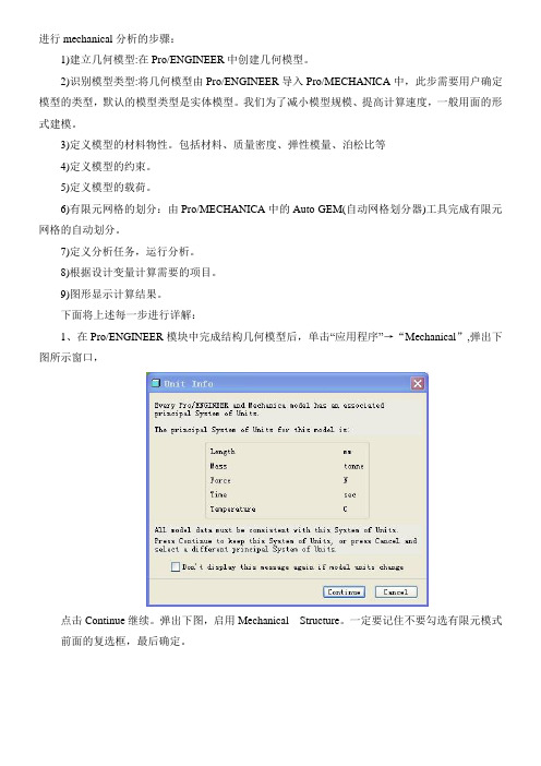
下面将上述每一步进行详解:1、在Pro/ENGINEER模块中完成结构几何模型后,单击“应用程序”→“Mechanical”,弹出下图所示窗口,点击Continue继续。
弹出下图,启用Mechanical Structure。
一定要记住不要勾选有限元模式前面的复选框,最后确定。
2、添加材料属性单击“材料”,进入下图对话框,选取“More”进入材料库,选取材料Name---------为材料的名称;References-----参照Parrt(Component)-----零件/组件/元件V olumes-------------------体积/容积/容量;Properties-------属性Material-----材料;点选后面的More就可以选择材料的类型Material Orientation------材料方向,金属材料或许不具有方向性,但是某些复合材料是纤维就具有方向性,可以根据需要进行设置方向及其转角。
点选OK,材料分配结束。
3、定义约束1):位移约束点击,出现下图所示对话框,Name 约束名称Number of Set 约束集名称,点击New可以新建约束集的名称。
Reference 施加约束时的参照,可以是surfaces(面)、edges/curves(边或曲面)、points(点)等Coordinate System 选择坐标系,默认为全局坐标系Translation 平动约束(Free为自由,fixed为固定,Prescribed为指定范围)Rotation 旋转约束单位为度Individual--------------单独的、孤立的Surf Options----------面选项Part Boundary---------零件的选择。

基于惯性参数的动力总成悬置系统解耦分析周宇杰;雷刚;贺艳辉;张骑虎【摘要】基于传统的动力总成悬置系统6自由度模型,可得到与6自由度相关的解耦率.而通过商业软件Adams建立动力总成悬置系统模型并利用vibration插件进行计算时,平动方向上的解耦率与传统6自由度模型相同,而转动方向上的三个分量被分解为6个与惯性参数相关的分量.基于Adams模态能量表达,用Matlab软件编写动力总成悬置系统的解耦率计算程序,利用多目标优化方法对悬置系统进行优化设计.结果表明,对悬置刚度进行优化能有效提高解耦率.%The decoupling rate associated with 6 DOFs is obtained based on the traditional 6-DOF model of powertrain mounting systems. The model of the powertrain suspension system is built by means of commercial software Adams, and the plug-in vibration code is used for calculation. In the calculation, the decoupling rate in the translation direction is the same as that of the traditional 6-DOF model, but the three components in the rotational direction is divided into 6 components which are related to the inertial parameters. Based on the expression of Adams modal energy, the Matlab software is used to write the program for decoupling rate computation of the powertrain mounting system. Finally, the optimization design of the mount system is carried out by using the multi-objective optimization method. The results show that the optimization of the mount stiffness can effectively raise the decoupling rate.【期刊名称】《噪声与振动控制》【年(卷),期】2017(037)006【总页数】4页(P94-97)【关键词】振动与波;振动解耦;多目标优化;悬置系统【作者】周宇杰;雷刚;贺艳辉;张骑虎【作者单位】重庆理工大学汽车零部件制造及检测技术教育部重点实验室,重庆400054;重庆理工大学汽车零部件制造及检测技术教育部重点实验室,重庆400054;重庆理工大学汽车零部件制造及检测技术教育部重点实验室,重庆400054;重庆理工大学汽车零部件制造及检测技术教育部重点实验室,重庆400054【正文语种】中文【中图分类】U260.331+.5汽车动力总成悬置系统是汽车振动系统中一个重要的子系统,该系统性能的优劣直接影响整车NVH性能。

第1期客车技术与研究BUS & COACH TECHNOLOGY AND RESEARCH No.l 201723蘿型后置后驱客车动力总成悬置系统设计关友印(辽宁曙光汽寧羣团技术中心丹东118000)摘要:使用扭矩轴理论和打击中心理论,对某型.后置后驱客车发动机悬置系统进行设计,并进行样车试验结果表明,按照以上方法设计的悬置系统真有良好的解耦致果,振动舒适.性较好。
关键词:后置后驱客车;动力总成;悬置系统;解耦设计中图分类号f_t3461.6 文献标志码:B文章编号:1006-3_331(__2017)01-0023-03 Design of Powertrain Suspension System of a Rear-mounted and Rear-driven CoachGuan Youyin(Technical Center, Liaoning SG Automotive Group Co., Ltd, Dandong 118000, China) Abstract: This paper discusses the design of the engine suspension system of a rear-mounted and rear-driven coach according to the theories of torque axis and percussion center, and does the sample tests. The results show that the suspension system designed in accordance to the above two theories has good decoupling effect and vibration comfort.Key words:rear-mounted and rear-driven coach; powertrain; suspension system; decoupling design随着人们生活水平不断提升,对乘坐舒适感的要求 也越来越高。

噪音振动(NVH)诊断套装识别车辆振动故障实例作者:暂无来源:《汽车维修与保养》 2015年第8期一辆2004年生产的大众高尔夫2.0 TDI轿车,发动机代码为BKD,整个车舱在67—73英里/小时(1英里=1.60 9干米)这个特定速度范围内会产生明显的振动。
为了避免振动车主不得已将行驶速度定在65英里/小时或75英里/小时。
通过方向盘传来的振动并不明显,车主也确认4个车轮和轮胎都已做过平衡。
对于任何形式的诊断,跟车主确认症状是至关重要的,而在检查振动噪音时,这点也至关重要。
因为我们每个人对噪音和振动的感知是不同的。
以笔者多年技师经验所知,令车主讨厌的东西可能来自于车辆自身的特性。
迄令为止,向车主证明这个事实,要取决于车主和技师之间的融洽、信任程度。
现在,有了Pico的噪音振动(NVH)诊断套装,我们可以对振动量进行物理测量,并向车主展现来自他们车辆的事实证据i甚至可以测量另一辆车的数据供其比较。
这样可以解释振动量是车辆自身特性,还是需要修理或更换一个部件(从检测到的振动频率识别)。
那么,噪音振动(NVH)诊断套装是如何检测和识别车辆中存在的众多振动?为了帮助回答这个问题,我们将Pico的NVH套装安装在上述的大众高尔夫上。
一、噪音振动(NVH)诊断套装NVH套装包含一个带磁座的加速度计,它通常被安装在驾驶员座位导轨上(图1)。
这是因为该导轨安装在底盘上,且是车主反映振动的来源。
这个位置是振动测量的原始标准位置(NVH 套装还包括用于噪音测量的麦克风)。
将加速计连接到NVH接口盒,接口盒通过BNC线缆连接到PicoScope示波器的通道B。
加速计检测到的任何振动都会通过接口盒传送到示波器通道B。
最后一步是将USB至OBD式通用诊断仪(解码器)(NVH套装不包含)连接到PC电脑和车辆OBD系统。
该诊断仪(解码器)向NVH 软件提供发动机的转速和车速(如果适用),软件基于此数据计算多个部件的旋转速度(频率)。

重型汽车动力总成悬置NVH性能研究运伟国;王邵斌;杨少华【摘要】The powertrain mount system of a heavy-duty truck is studied. The vibration isolation principle of the system and the fundamental principle for design are analyzed theoretically. Furthermore, through the numerical simulation and real testing of the vehicle, the frequency distribution of the rigid-body modal of the powertrain, energy decoupling degrees of modals of different orders, the vibration isolation rate of the powertrain mount and the vibration RMS values at some key points in the cab, are studied respectively for 4 point suspension and 4+2 point suspension arrangements of the truck’s powertrain. The results show that the 4 point suspension arrangement is better for the vehicle traveling on a nice even road than the other. However, the 4+2 point suspension arrangement is recommended for vibration reduction of the vehicles traveling on poor uneven roads.%以某重型汽车动力总成悬置系统为研究对象,从理论上分析动力总成悬置的隔振原理及设计的基本原则,通过仿真计算与实车试验相结合研究重型汽车常见的4点悬置与4+2点悬置布置型式对动力总成刚体模态频率分布、各阶模态解耦、悬置在各工况时的隔振效率及驾驶室内关键点振动的影响。
DESIGN INSPIRATIONBinary Mod Owner's ManualWelcomeCongratulations on your new Hotone Binary pedal! You have just added some serious power to your pedalboard.The Binary series lets loose versatile pro effects in compact cases. A dual-DSP powered platform and CDCM modeling systemensure a realistic playing experience, dual-footswitch design and variable I/Os make it easy to use, and an OLED screen offersclear, detailed display.Binary Mod is a CDCM-based multi modulation effects pedal with stereo I/O and expression pedal support, delivering preciseclassic modulation pedal sounds along with new and inspiring Hotone original modulation effects.Features✪ Grown out of next-gen XTOMP technology✪ Compact, easy-to-use dual footswitch modulation pedal with tap tempo✪ Advanced CDCM modeling system ensures realistic playing experience✪ Dual DSP-powered platform ensures high sound quality✪ 24-bit A/D/A conversion, up to 110dB S/N ratio✪ 24 high quality modulation effects including CDCM-based classics and Hotone originals✪ Tap Tempo function with Tap Divide✪ Stereo I/Os✪ EXP jack for expression pedal control✪ USB jack for firmware upgrading, loading/managing effects with free PC/Mac software✪ 10 Presets (2 banks x 5 patches)✪ Built-in OLED screen with clear display✪ 5 transparent knobs with LEDs✪ 9V DC power supplyPanel Introduction1. ON/OFF: For switching the unit on/off. The LEDs under the upper 5 knobs indicateeffect on/off status.2. PATCH/TAP: Tap for selecting forward patches in current bank, hold forengaging/disengaging tap tempo mode.3. +/- buttons: For selecting effects and adjusting parameters.4. GLOBAL: For setting expression pedal, input mode, and other parameters.5. SAVE/EXIT button: For saving or canceling parameter changes.6. OLED screen: Shows bank/patch numbers, setting values and other operation info.7. E.LEVEL: Controls effect output level (varies with effects).8-9. A/B: Control detailed effect character (varies with effects).10. DEPTH: Controls effect depth (varies with effects).11. RATE: Controls the effect speed (varies with effects). In Tap Tempo mode, use RATE knobto set a Tap Tempo subdivision*, and the RATE LED will keep flashing.12. INPUT: 1/4” (6.35mm) stereo jack, for plugging in instruments or other effects.A Y cable is needed when connecting to stereo pedal outputs.13. EXP: 1/4” (6.35mm) TRS jack, for connecting an expression pedal.The expression pedal should have a TRS cable attached to it.We recommend using a Hotone Soul Press (switched to EXP mode) for expression control.14-15. OUTPUT (L & R): 1/4” (6.35mm) mono jacks, for connecting to amps or other effects.16. USB jack: Mini USB jack, for effects editing, firmware updates, and factory reset.17. DC 9V: Plug in your power supply here (DC 9V, center negative).*Requires firmware v1.1.2 or laterConnectionsNote: TURN ON FIRST, TURN OFF LAST. Always turn down the volume knob on your amp before plugging or unplugging power jacks, cables, etc.DisplayPlugging in your power supply will turn on the device. The main display will come up as shown below:1 - Current bank/patch number2 - Shows the expression pedal controlled parameter3 - Indicates the effect model you’re using in current patchSelect a Patch/BankTap the PATCH footswitch once to switch to the next patch. Tap it repeatedly to cycle through patches of the current bank in theorder 1, 2, 3, 4, 5, then 1.Tap the two footswitches at the same time to switch to the next bank. Tap them repeatedly to cycle through banks in the order A,B, then A.Tap TempoHold the PATCH/TAP footswitch to engage Tap Tempo mode when the effect is on. Then tap the PATCH/TAP footswitch to set a tempo speed.In this mode, the LED under the RATE knob will pulse to indicate the effect rate you set. Hold the PATCH/TAP footswitch again to disengage.In Tap Tempo mode, turn the RATE knob (or any related knobs) to set a proper tap tempo subdivision shown as below:SUBDIVISIONWhole NoteHalf NoteDotted Half NoteHalf Note Triplet Quarter Note (no division) Dotted Quarter Note Quarter Note Triplet8th NoteDotted 8th Note8th Note Triplet16th Note DIVIDE RATIO4234/31/13/22/31/23/41/31/4DISPLAY11/21/2D1/2T1/41/4D1/4T1/81/8D1/8T1/16Note: 1. The default division is Quarter Note (1/4, no division). Disengaging Tap Tempo function will reset the subdivision to default.2. Tap Tempo subdivision function requires firmware v1.1.2 or later.GlobalPress the GLOBAL button repeatedly to cycle through input mode, expression pedal settings and firmware version info:Use the +/- buttons to set the parameters, press the SAVE/EXIT button (or wait for 5 seconds without any operation) to confirm settings and exit to the main display.Note: 1. There is no parameter in firmware info display.2. To check firmware version on your Binary Mod, you need to update to firmware v1.1.1 or later.Edit1. Adjust the parametersUse the onboard knobs to adjust the effect parameters. The screen display will be shown as below when adjusting:1 - Current parameter value you’re adjusting (shown: rate)2 - Saved parameter value in the current patch (PREV. = Previous value)2. Select a different effectUse the +/- button to change to another effect:The inverted bank/patch number indicates that the current patch has been edited.3. Set the expression pedalIf you have an expression pedal, you can control an effect parameter in real time.In main display, press the GLOBAL button twice to edit control target:Use the +/- buttons to select a target among E.LEVEL, A, B, DEPTH, RATE.Note: If you change to another patch before saving your edits, all your changes will be lost. Save the patches to keep your changes.Hold the SAVE/EXIT button to activate save function. The screen will be shown as below:Use the +/- buttons to choose a location. Tap the SAVE/EXIT button to confirm saving. Tap either footswitch to cancel saving and go back to edit status.Input ModeIn main display, press the GLOBAL button once to select an input mode:Use the +/- buttons to choose from MONO and STEREO. If you choose to use STEREO mode while using mono (L) input,the right output will be MUTED.This is a global setting (it won’t change your patches) and changes will be automatically saved.In main display, press the GLOBAL button three times/four times to set the minimum/maximum value ranging from 000 to 100: 3 times (min value) 4 times (max value)Note: 1. The minimum value cannot be set higher than the maximum value.2. This is a global setting (it won’t change your patches) and changes will be automatically saved.The expression pedal can be calibrated if necessary. If there does not seem to be much effect even when you press the pedal, or effects change greatly when the pedal only moves slightly, use the following procedure to readjust it.In the main display, press the GLOBAL button five times:Press + button to activate calibration and then screen displays “HEEL POSITION”:Press the pedal all the way back towards the heel and press + button, and then it displays “TOE POSITION”:Press the pedal all the way forward towards the toe and press + button.After finishing the adjustment, “CALIBRATION COMPLETE” will appear and it will go back to the main display.If “PLEASE TRY AGAIN” appears, do the calibration from “HEEL POSITION” again:Effect Models List**The Manufacturers and product names mentioned above are trademarks or registered trademarks of their respective owners. The trademarks were used merely to identify the sound character of the products.DescriptionE.LEVEL A B DEPTH RATE TAP TARGET01Grand Chorus (GRD CHO)Based on the legendary green ensemble chorus (chorusmode)E.LEVEL Low Cut (LO CUT)High Cut (HI CUT)DEPTH RATE RATE 02Sky Chorus (SKY CHO)Based on the Arion SCH-1Stereo ChorusE.LEVEL Low Cut (LO CUT)High Cut (HI CUT)DEPTHRATE RATE 03Tiny Chorus (TINY CHO)Based on Electronic-Harmonix Small Clone E.LEVELLow Cut (LO CUT)High Cut (HI CUT)Extra depth on/off selector (DEEP):OFF/ON RATERATE043D Chorus (3D CHO)Poducing a multi-dimensional chorus with independent depth control on left,center and right sound channels MIX Left channel depth (DEPTH L)Center channel depth (DEPTH C)Right channel depth(DEPTH R)RATE RATE 05Stereo Chorus (ST CHO)Producing a magical stereo chorus effect with spreadcontrolMIX Chorus dimension/Spread separation (SPREAD)TONE DEPTH RATE RATE 06Bass Chorus (BASS CHO)Based on world's first bass chorus pedalE.LEVEL Low Cut (LO CUT)High Cut (HI CUT)DEPTH RATERATE 07Detune (DE TUNE)Producing a slightly pitch-shifted signalcombineswithoriginal signalDRY LowCut (LOCUT)High Cut(HICUT)WET Detune range (RANGE)NONE 08Normal Flanger (NORM FLG)Producing classic flanging effectE.LEVEL PreDelay (PREDLY)Feedback (F. BACK)DEPTH RATERATE 09Trem Flanger (TREM FLG)Producing classic flanging effectcombining withtremolo effect OUTPUT Tremolo Depth (T.DEPTH)TremplpRate (T.RATE)Flanger Depth (F.DEPTH)Flanger Rate (F.RATE)RATE 10Bass Flanger (BASS FLG)Producing flanging effect designed forbass E.LEVEL PreDelay (PRE DLY)Feedback (F. BACK)DEPTH RATE RATE 1190Phaser (90PHS)Based on MXR Phase90OUTPUT Low Cut (LO CUT)High Cut (HI CUT)DEPTH RATE RATE 12Green Phaser (GRN PHS)Based on legendary 2-knob green phaser with sharpphasing effect OUTPUT LowCut(LOCUT)HighCut(HICUT)DEPTH RATERATE13Pan Phaser (PAN PHS)Producing a special phaser effect combing smooth tremolo (mono output)/pan(stereo output) variations OUTPUT Tremolo/Pan Depth(T. DEPTH)Tremolo/Pan Rate(T. RATE)Phaser Depth (P .DEPTH)Phaser Rate (P .DEPTH)RATE 14Helicopter Tremolo (HELI TREM)Based on Demeter TremulatorOUTPUT LowCut (LOCUT)High Cut(HICUT)DEPTH RATE RATE15Opto Tremolo (OPTO TREM)Simulates classic pulsing tremoloeffect on '60sAmerican ampsOUTPUT Tremolo tone(COLOR)Waveform biasoffset(BIAS)DEPTH RATE RATE 16Bias Tremolo (BIAS TREM)Simulates vintage bias tremolo effectonlate'50sBritish ampsOUTPUT Tremolo tone (COLOR)Waveform bias offset (BIAS)DEPTH RATE RATE 17LUSH ROTO Based on Shin-Ei Uni-Vibe OUTPUT Low Cut (LO CUT)High Cut (HI CUT)DEPTH RATE RATE 18MINI ROTO Based on Voodoo Lab Micro VibeOUTPUT Low Cut (LO CUT)High Cut (HI CUT)DEPTH RATERATE 19Grand Vibrato (GRD VIB)Based on the legendary green ensemble chorus (vibratomode)OUTPUT Low Cut (LO CUT)High Cut (HI CUT)DEPTH RATE RATE 20Blue Vibrato (BLUE VIB)Based on the legendary blue,BBD-based vibrato pedalOUTPUT Low Cut (LO CUT)High Cut (HI CUT)DEPTHRATERATE 21TRON WAH Based on Electronic-Harmonix Q-TronSENS Filter sweeping direction (SWP):DOWN/UPEnhances low bottomor high overtones (RNG):LO/HIFilter resonance (PEAK)How fast the filter goes backto the resting point (DECAY)NONE 22AUTO WAHFully controllable band pass filter with variable autowah effectsOUTPUT Filter range (FREQ)Filter sharpness (Q)DEPTH RATERATE 23RING MOD Ring modulatorwith interesting inharmonic,bell-likefrequency spectraMIX TONE Modulate frequency range(MODE):LO/HI Ring mod frequency(FREQ)Ring mod frequency finetuning (FINE)NONE 24LO FIProduces bitcrushing/sample reducing effectMIXLow Cut (LO CUT)High Cut (HI CUT)KRUSHBITNONESpecificationsNumbers of Effects: 24Numbers of Patches: 10 (2 banks x 5 patches)Digital Processing: 24-bit A/D/A conversion, 44.1 kHz sample rateFrequency Response: 20 Hz-20 kHzS/N Ratio: Up to 110dBInput Impedance: 1M OhmsOutput Impedance: 100 OhmsPower Requirement: DC 9V, center negativeCurrent Consumption: 200mA minimumDimensions: 121mm (D) x 72mm (W) x 47mm (H)Weight: 340gThe contents of this manual are subject to change without notice.。
NVH分析建模指南NVH分析建模指南 (1)1.单位制 (3)2.材料和物理属性 (3)2.1 材料属性 (3)2.2 物理特性 (4)3. NVH有限元建模 (4)3.1 NVH有限元建模步骤 (4)3.2网格尺寸 (5)3.3单元质量标准 (5)4.网格划分细则 (6)4.1孔的处理 (6)4.2 过渡圆角/倒角的处理 (7)4.3 加强筋的处理 (7)5 连接 (8)5.1螺栓连接 (8)5.2 缝焊(电弧焊、C02保护焊、钎焊、激光焊) (8)5.3点焊(压力焊) (9)5.4 粘合剂/橡胶/胶 (10)6 命名规则 (11)6.1 模型分类 (11)6.2 零件命名规则 (11)6.3模型命名规则 (12)1.单位制大部分的CAE软件对单位制一无所知,因此在分析中必须由用户来保持单位一致。
Abaqus 运算推荐使用推荐单位制标准一,Nstran 运算推荐使用单位制标准二。
建议在输入文件中对所使用的单位系列加以注释。
单位制对应关系见表1.1。
表1.1 单位制2.材料和物理属性2.1 材料属性在Nastran中,各向同性的线性材料属性是在卡片“MA T1”中指定的。
可参考数据表格“主要汽车材料”。
推荐使用试验中获得的材料属性数据见表2.1。
表2.12.2 物理特性Nastran中,大部分单元的属性在“定义”卡片和“属性”卡片中定义。
“定义”卡片用来指明单元之间的节点连接;“属性”卡片用来指明单元的固有属性,例如,厚度。
每个单元都需要一个定义卡片。
只要属性相同,类型相同的单元可以共用一个属性卡片。
但是在整车分析中,每个部件一般都具有独立的单元属性,因此,建议使用与部件序号相同的单元属性定义号。
3. NVH有限元建模3.1 NVH有限元建模步骤●导入CAD数据并进行几何模型修改●自动进行网格划分,部分区域要求手动网格划分●检查网格质量并修改●指定材料类型和参数●指定单元属性和材料●连接部件●组装子系统●加载边界条件●最终检查网格划分是建模的第一步,在网格划分时要采用如下方案:1)采用单元offset建模法避免模型干涉;2)采用中间平面建立网格模型;3)保留主要几何线,网格要与几何保持良好的贴合;4)需要布置焊点处最少要画一排平行网格,焊点位置容许适当采用三角形单元,如图3.1;图3.15)实体单元最少要三排以上,如图3.2所示;图3.26)关键区域单元应尽可能规则并细化,在粗细网格之间应有过渡单元;7)壳曲或凸起的高度<5mm,忽略;8)防止集中出现翘曲单元和三角形单元;9)三角形单元数不应超过单元总数的10%。