FTTCab-20B室外机柜用户手册
- 格式:doc
- 大小:355.00 KB
- 文档页数:3

FTTB户外机柜技术方案(3台64+128)
1.结构尺寸及布局
1.1简述:
该机柜采用单舱落地或架空结构形式,前后开门,机柜采用夹芯层结构,中间垫隔热棉,机柜主体结构焊接,部分拼装,主要材料为优质热浸锌板,内外表面喷户外粉。
1.2外形尺寸
图1-2 外形尺寸
1.3内部布局
主设备舱宽度满足19英寸标准机框安装要求,其安装立柱高度为23U,设备安装空间为14U;
蓄电池位于设备舱底部,可提供4个大小为257(长)x176(宽)x166(高)的50AH蓄电池。
MDF最大安装容量为600外线模块,768内线模块;
主设备舱设备布局,如图1-2所示;
图1-2 设备布局
2.配置表
序号 存货编号
(料号)
名 称 规格
单
位
数
量
备注
1 柜体
高*宽*深
1550mmX750mmX750mm
set 1
1、含光缆固定板、接地铜排等
2、机柜材料热浸锌钢板
2 主设备舱风扇组件 含4个直流风扇、温控器set 1
3 交流防雷配电单元 C级防雷,交流1路32A
输入,1路20A输出, 6
路10A输出,3U高
set 1
4 蓄电池 12V/50Ah set 4
5 电源系统 GP4860,-48V/40A set 1
6 电源排插模块 set 1
7 保安接线排 25回线 set24
8 测试接线排 32回线 set32
9 保安单元 set600
10 XD-B1打线刀 set 1
11 19英寸12口光纤配线
盒 GC-BS-P1FC
set 1。
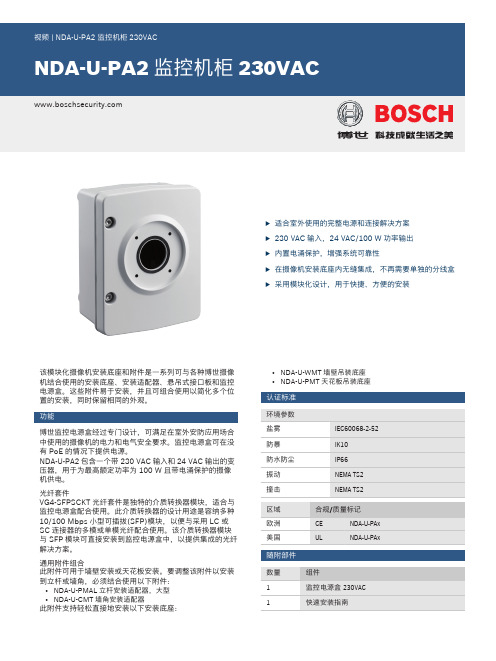
u 适合室外使用的完整电源和连接解决方案u 230 VAC 输入,24 VAC/100 W 功率输出u 内置电涌保护,增强系统可靠性u 在摄像机安装底座内无缝集成,不再需要单独的分线盒u采用模块化设计,用于快捷、方便的安装该模块化摄像机安装底座和附件是一系列可与各种博世摄像机结合使用的安装底座、安装适配器、悬吊式接口板和监控电源盒。
这些附件易于安装,并且可组合使用以简化多个位置的安装,同时保留相同的外观。
功能博世监控电源盒经过专门设计,可满足在室外安防应用场合中使用的摄像机的电力和电气安全要求。
监控电源盒可在没有PoE 的情况下提供电源。
NDA-U-PA2包含一个带230 VAC 输入和24 VAC 输出的变压器,用于为最高额定功率为100 W 且带电涌保护的摄像机供电。
光纤套件VG4-SFPSCKT 光纤套件是独特的介质转换器模块,适合与监控电源盒配合使用。
此介质转换器的设计用途是容纳多种10/100 Mbps 小型可插拔(SFP)模块,以便与采用LC 或SC 连接器的多模或单模光纤配合使用。
该介质转换器模块与SFP 模块可直接安装到监控电源盒中,以提供集成的光纤解决方案。
通用附件组合此附件可用于墙壁安装或天花板安装。
要调整该附件以安装到立杆或墙角,必须结合使用以下附件:•NDA-U-PMAL 立杆安装适配器,大型•NDA-U-CMT 墙角安装适配器此附件支持轻松直接地安装以下安装底座:•NDA-U-WMT 墙壁吊装底座•NDA-U-PMT 天花板吊装底座认证标准随附部件技术指标尺寸(单位:毫米(英寸))订购信息NDA-U-PA2 监控机柜230VAC监控电源盒,230 VAC输入,24 VAC输出,IP66订单号NDA-U-PA2附件NDA-U-WMT 悬吊式壁装适用于球型摄像机的通用壁装底座,白色订单号NDA-U-WMTNDA-U-CMT 角落安装适配器通用墙角安装底座,白色订单号NDA-U-CMTNDA-U-PMAL 立杆安装适配器(大)通用立杆安装适配器,白色;大型订单号NDA-U-PMALNDA-U-PMT 悬吊式管道安装,12" (31cm)适用于球型摄像机的通用管道安装底座,31厘米,白色订单号NDA-U-PMTSFP-2 光纤模块,多模,1310纳米,2LCSFP光纤模块,2千米(1.2英里),2个LC连接器。

ZPX-415型违法闯红灯抓拍系统技术说明书编制:___________审核:___________工艺:___________标准化:___________批准:___________哈尔滨新中新猎豹电子工程有限公司目录一、概述: (1)二、结构特征 (1)三、安装和调试 (1)1、工控机单元安装调试技术要求: (1)2、工控机检验技术要求: (3)3、工控机箱检验技术要求: (5)4、机柜排风风扇安装技术要求: (5)5、机柜检验技术要求: (5)6、摄像机检验技术要求: (6)7、防护罩检验技术要求: (6)8、闪光灯检验技术要求: (6)四、整机检验技术要求: (6)五、硬件狗驱动板整机检验技术要求: (8)六、并口检测板检验技术要求 (9)七、红灯检测技术要求 (11)八、显示板检测技术要求 (11)九、温控板检测技术要求 (12)十、闪灯驱动板检验技术要求 (13)十一、故障分析与排除 (14)十二、维修和保养 (14)十三、产品成套器材 (14)一、概述:本说明书用于指导制造过程中的安装、调试、检验以及包装、存储等事项。
本说明书中未提及的与制造有关的其它部分,按常规方法和要求进行。
二、结构特征ZPX-415型违法闯红灯抓拍系统总体结构可分为主机部分和前端部分。
前端部分包括闪光灯组件和摄像机组件,主机部分包括防护机柜、工控机、检测控制单元、温控单元、闪光灯驱动单元、面板显示单元等,通过扁平连接线缆和导线相连接。
闪光灯组件由防护罩、闪光灯组成。
闪光灯组件的数量是根据抓拍的总车道数量确定的,即每个车道对应1个闪光灯组件。
摄像机组件由摄像机、摄像机防护罩、安装支架、开关电源等组成,它与抓拍主机的摄像机电源输出端子和工控机的视频输入端子相连接;它的数量由抓拍的方向数和车道数来确定。
闪光灯组件和摄像机组件单独包装。
三、安装和调试1、工控机单元安装调试技术要求:1、参照样机明确要装配的主板、并口、视频卡、电子盘和数据硬盘的位置,如图。

机柜使用说明书1.概述本机柜为19英寸标准计算机机柜,主要用于网络、监控、计算机等领域,具有所有机柜的一般通用性尺寸规格:2000mm(不含轮脚)X 1100mm(深度)X 600mm(宽度)内部有效高度:42U颜色:黑色砂纹。
2.使用环境条件(1).工作电压:AC 220V~380V(2).工作温度:-5℃~+40℃(3).存储温度:-25℃~+55℃(4).相对湿度:5%~80%(5).机柜有效放置空间距离:≥2M(6).机房散热条件:内装空调(7).机房内部防雷、防静电装置:机房需内装接地及防雷电设施(8).消防报警及灭火系统:机房需安装因出现电路起火的报警装置及灭火设备机房内所有使用环境需要配备相应的检测设备:如温度计,湿度计等,若机柜存放于没有机房的环境工作,则需要房间具有空气流通条件形成对流,必要时可以在机柜内部配装风机散热。
3.系统的主要功能和主要指标(1).机柜的主要功能是将所有设备集成在机柜内部,便于安装调试、维护和管理,使机柜成了设备运行的载体,从而达到高效、安全的工作效果。
(2).LCD显示屏,便于集成显示用户需要的技术参数。
(3).相关指标:安全防护等级:IP45ESD:机柜内部前后门均接地脚轮载重:≥600KG机柜静态载重:≥1000KGGB/T 19520.1-2007 GB/T 19520.1-2007 电子设备机械结构482.6 mm(19 in)系列机械结构尺寸第1部分:面板和机架GB/T 19520.2-2007 电子设备机械结构482.6 mm(19 in)系列机械结构尺寸第2部分:机柜和机架结构的格距《公差标准》(GB1804-2000/GBT1184-1996)《喷涂质量标准》(GB/T5237.5-2000)4.产品特点及说明(1).机柜前门采用铝型材和弧形造型设计,使机柜整体具有较新颖和线条美感,前后门均为通风网孔,增加美感同时满足设计运行的散热要求,其外形有如下特点。

户外机柜技术规范通信⽤户外机柜(含户外机房电源)技术规范2011年7⽉前⾔本技术规范综合考虑了国家节能减排政策要求、基站建设和维护需求等。
本技术规范参考相关国家标准、通信⾏业标准⽽制定。
本项技术规范将推进通信⽤户外机柜的产业化进程,促进企业技术进步,提⾼产品质量,有利于产品的规范,有利于产品应⽤,更有利于引导⾏业产品的发展⽅向。
⽬录1 范围 (3)2 规范性引⽤⽂件 (4)3 定义 (4)3.1通信⽤户外机柜 (4)3.2 相变机柜.......................................................................................... 错误!未定义书签。
4 产品的分类 (5)5 使⽤要求 (5)5.1基本⼯作条件 (5)5.2环境温度 (5)5.3相对湿度 (5)5.4 ⼤⽓压⼒ (5)5.5 电源 (5)5.5.1交流电源 (5)5.5.2直流电源 (5)6 技术要求 (8)6.1 结构要求 (8)6.2 柜内温度控制.................................................................................. 错误!未定义书签。
6.3 寿命 (9)6.4噪⾳要求 (9)6.5⾃动控制要求 (9)6.6告警及监控要求 (9)6.7 显⽰要求 (9)7检验规则 (10)7.1 检验分类 (10)7.2 出⼚检验 (10)7.2.1 全检 (10)7.2.2 抽检 (10)7.3 型式试验 (10)8标志、包装、运输、贮存 (11)8.1 标志 (11)8.1.1产品标志 (11)8.1.2包装标志 (11)8.2 包装 (11)8.3 运输 (11)8.4 储存 (11)9 户外通信机柜对⽐................................................................................. 错误!未定义书签。

GSM BTS操作维护手册目录第一章基站类型 (3)1.1 室内型基站 (3)1.1.1设备外观及机架基本结构 (3)1.1.2设备的基本尺寸及重量 (4)1.1.3设备的供电范围及功耗 (4)1.2室外型基站 (5)1.2.1设备外观及机架基本结构 (5)1.2.2设备的基本尺寸及重量 (7)1.2.3设备的供电范围及功耗 (7)1.2.4设备存放及运行的环境要求 (7)第二章机柜的命名规则及配置规范 (8)2.1机柜的命名规则 (8)2.2 配制表 (8)2.2.1 室内标准直流配置表 (8)2.2.2 室内低损高功直流配置表 (9)2.2.3室外标准配置表 (9)2.3 双载频配置文档 (10)第三章子框接口,内部接口及子框背板数据线 (10)3.1标准子框STASR及后背板STABP接口 (10)3.2内部接口板(Interconnection Panels) (11)3.2.1 室内型MBI3,MBI5机柜内部连线接口板 (11)3.2.2 室外型机柜CBO1,MBO1内部连线接口板OUTC (12)3.3数据控制总线(背板排线) (13)第四章模块类型和连线 (14)4.1主控板SUMA (SUMP) (14)4.2载频 (15)4.3双工器 (15)第五章调测步骤 (16)5.1 BTS调测 (16)5.1.1准备BTS(B10)调测环境 (16)5.1.2 下载BTS软件 (16)5.1.3 编辑Qmux(Q1)地址 (17)5.1.4 编辑RI机架扫描文件 (17)5.1.5 设置基站名 (17)5.1.6 编辑小区号 (17)5.1.7 模块检测 (18)5.1.8 检查RF连线 (18)5.1.9 设置TMA (19)5.1.10双载频设置 (20)5.1.11激活全部小区 (20)5.1.12可选:初始化power down计数器 (21)5. 1.13 可选:设置PM12参数 (21)5.1.14可选:设置电池参数 (22)5.1.15设置和检查告警映射 (23)5.1.16外部告警环断测试 (24)5.1.17检查模块状态 (24)5.1.18VSWR驻波比校验 (24)5.1.19 风扇单元测试 (26)5.1.20保存测试文件 (26)5.2连接BSC (27)5.3结束调测 (27)第六章扩容、减容及添加小区 (27)6.1 减容步骤 (27)6.2 扩容步骤 (29)6.3 如何增加小区 (30)第七章基站告警模块更换方法 (32)7.1 OUTC板更换流程 (32)7.2 XIBM板更换流程 (35)第一章基站类型1.1 室内型基站1.1.1设备外观及机架基本结构Evolium A9100 MBS Indoor BTS简称MBI,根据机架不同要分为MBI3和MBI5两种,如图:MBI3外观MBI5外观以下是设备机架的基本结构:MBI3机架基本结构MBI5机架基本结构1.1.2设备的基本尺寸及重量MBI5 MBI3设备基本尺寸宽度600mm 600mm深度450mm 450mm高度(20mm可调节)1940mm 1300mm每个机架的平均重量空机架:100kg 空机架:77kg最大配置:270kg 最大配置:150kg 电池平均重量(可选)BU101:120kg BATS:14kgBATS:14kg1.1.3设备的供电范围及功耗设备采用-48V/-60V通信直流电源,对于直流电源要求如下:-48V/-60V ±20%1.1.4设备存放及运行的环境要求A9100 MBS INDOOR BTS运行环境要求参考下表:1.2室外型基站1.2.1设备外观及机架基本结构室外型基站分Evolium A9100 MBS Outdoor BTS(简称MBO)和9100 Compact BTS Outdoor (简称CBO)两种机柜,两种机柜又可采用AC和DC两种供电方式CBO1 MBO1 以下是设备机架的基本结构:1.2.2设备的基本尺寸及重量尺寸大小(mm) 平均重量(kg)MBO1(不含电池)H=1500 240W=850D=700CBO1(不含电池)H=902 140W=720D=700电池单元120至150 1.2.3设备的供电范围及功耗设备可采用直流/交流两种方式供电,交流电源供电要求如下:范围:230V±17% 380V±17%频率:47至63Hz直流电源供电要求如下:范围:-48V±20%1.2.4设备存放及运行的环境要求A9100 MBS OUTDOOR BTS的存放及运行环境要求参考下表:第二章机柜的命名规则及配置规范2.1机柜的命名规则1x1...4 1 sector with up to 4 TREs3x1...2 3 sectors with up to 2 TRXs per sector1x1...2/1x1...2 Multiband configuration, with 1 sector and up to 2 TREs in Band 1, and 1 sector and up to 2 TREs in Band 21x(...2/...2) Multiband configuration, with 1 sector and up to 2 TREs in each band1小区含4载频3小区每小区含2载频多频段配置,一个小区1频段含2载频,另一个小区2频段含2载频多频段配置,一个小区含两频段,每个频段2载频2.2 配制表设备配置主要分在室内和室外环境下工作的交流和直流两种模式。
WF(G)-11室外机柜产品说明书感谢购买本公司的产品,在您安装使用之前请认真阅读本说明书!1、概述WF(G)-11型通信用室外机柜是一种适用于户外的综合型接入网设备。
可满足宽带及交换机设备的安装(选配);电源的接驳;通信配线线路的成端;光、电线缆的进出;门禁的监控,并可提供门禁开关告警信号,具有良好的防盗性能;采用风扇强制制冷技术以及隔热保温设计,对室外机柜实现可靠的温度管理,确保柜内通信设备在高温和高寒等恶劣环境下的安全运行。
在户外安装条件下,可以抵御风沙、雨水、阳光的辐射的影响。
本设备由设备柜,蓄电池柜,风扇等组成。
2、机柜外形尺寸(见下图)3.产品的特点及功能3.1 柜体采用优质不锈钢做主材, 具有良好的机械及防腐性能,耐候性优良。
3.2 表面喷涂防紫外线粉末,双层隔热设计。
强度高,外型美观;3.3 标准19英寸安装方式,配置灵活;3.4 全正面化操作,节省机房空间;3.5 强弱电分开,有专门的走线槽,进缆跳线全正面化操作;3.6 有足够的光纤盘储空间,保证光缆、光纤的曲率半径;3.7 可靠完善的接地保护。
3.8 所有技术性能指标均符合GB4208-1993外壳防护等级IP55级.4.环境要求4.1 工作温度:-45℃~+55℃相对湿度:≤95%(+30℃)大气压力:70KPa~106Kpa 4.2 主要技术指标4.2.1 机柜部分◇机柜高压防护地与机柜绝缘,绝缘电阻>1000MV/500VDC◇机柜防护地与机柜间耐压>3000VDC/min不击穿,无飞弧5、设备的安装.户外机柜须安装在水泥基座或其它坚固可靠的基座上。
5.1水泥基座示意图(见下图)电池仓设备仓5.2机柜门的操作本设备的门锁采用专用钥匙进行的门的开启与锁闭。
开锁时,将锁盖板旋转开,将专用钥匙对入锁孔的凹槽,插入后向右旋转约75度,弹出锁体的把手,向右旋转把手,即可打开机柜门。
锁闭时,将把手向左旋转,对准把手槽压进槽内,拔出钥匙即可。
SmartZone™Gateway-EnabledMS Series Rack PDUUser ManualIM012Release1Issue2Gateway-Enabled MS Series Rack PDU User ManualCopyright©2018Panduit Corp.All rights reserved.No part of this book shall be reproduced,stored in a retrieval system,or transmitted by any means,electronic,mechanical,photocopying,recording or otherwise,without written permission from Panduit.No patent liability is assumed with respect to the use of the information contained herein.Although every precaution has been taken in the preparation of this book,Panduit assumes no responsibility for errors or omissions. Neither is any liability assumed for damages resulting from the use of the information contained herein.Gateway-Enabled MS Series Rack PDU User Manual Table of ContentsSmartZone™Gateway-Enabled MS Series Rack PDU4 Contacting Panduit4 Symbols Used4 Equipment Overview6 Box Contents6 Cable Details6 Voltage and Current Values7 Model Numbers7 Pre-Installation9 InstallationProduct Inspection10 Plug Connection10 Hardwiring10 Vertical Mounting11 Horizontal Mounting13 SmartZone1RU Inline Meters13 Optional Accessories14 Additional Required Items15 Safety Precautions15 Servicing15 Product Safety WarningsRules16 Environmental Specifications17 Bonding17 HardwareLCD Display18 Mode Button Operation18 Bootloader Startup18 Firmware Recovery Mode18 Application Startup19 Internal Error NotificationGateway User Interface21 Access the PDU Graphical User Interface21 Using the PDU Graphical User Interface22 Appendix A-Temperature Sensor Adapter Installation23 New Installations23 Existing Installations.Fitting the Adapter In-line.24Gateway-Enabled MS Series Rack PDU User ManualSmartZone™Gateway-EnabledMS Series Rack PDUGateway-Enabled MS (Monitored and Switched) Series Rack PDUs manage and dis-tribute power to multiple power devices through a single power connector.This PDU allows you to access,configure,and manage power consumption and environmental parameters from remote locations.The MS Series PDU monitors per-phase power,voltage and current,per-branch current, and includes the ability to switch the power to each outlet off or on.SmartZone™Gateway-EnabledPDUs are available in a widerange of configurations andpower connections and outletsand can be mounted vertically orhorizontally.Contacting PanduitFor Technical Support on PDU hardware and associated software,please contact Pan-duit Technical Support using one of the following methods:1-866-721-5302(toll-free)Monday-Friday,7:30am-5:00pm CST*************************Symbols UsedGateway-Enabled MS Series Rack PDU User ManualGateway-Enabled MS Series Rack PDU User ManualEquipment OverviewThe power inlet/cord(s)connects the PDU to the electrical power source.The LCD dis-plays the current load for each input feed or electrical phase per input feed.Box ContentsThe SmartZone Gateway-Enabled Rack PDU box contains the following: l Gateway-Enabled Rack PDUl Configuration Cablel CDl Mains Adapterl External Grounding StudCable Detailsl63A single and three phase feed cable–10mm²(0.40inches²)conductors:HO7cable type terminated with(1P)3-pin63A commando and(3P)5-pin63A com-mando(IEC60309)l32A single and three phase feed cable–6.0mm²(0.23inches²)conductors:HO7cable type terminated with(1P)3-pin32A commando and(3P)5-pin32A com-mando(IEC60309)l16A single and three phase feed cable–2.5mm²(0.10inches²)conductors:HO7cable type terminated with(1P)3-pin16A commando and(3P)5-pin16A com-mando(IEC60309)l13A single phase feed cable–1.5mm²(0.06inches²):HO7cable type ter-minated with3-pin UK plugl10A single phase feed cable–1.0mm²(0.04inches²):HO7cable type ter-minated with3-pin IEC C14PlugFor IEC C-20inlet PDUs,a customer-supplied cord is used for connection to the power source. The connection end to the PDU has an IEC C-19plug for connection to the PDU. The opposite end of the cord shall have a plug suitable for connecting to the cus-tomer supplied receptacle.The cord and plug shall be rated for20A in North America and16A outside of North America. The connection to the PDU should be made prior to connecting to the power source.Gateway-Enabled MS Series Rack PDU User Manual Voltage and Current ValuesModel NumbersThe following table lists the specifications for the Gateway-Enabled Rack PDU model numbers.In the tables above,www is the voltage for single phase or3-phase and xx is the pos-sible current associated with the voltage.Refer to the chart below for valid International and U.S.values.Gateway-Enabled MS Series Rack PDU User ManualGateway-Enabled MS Series Rack PDU User ManualPre-InstallationThe Gateway-Enabled Rack PDU products covered by this guide are designed to be installed within EIA racks and cabinets. Use of this product in other applications is acceptable,but other precautions may be required to allow for specific installations not covered by this guideline.Gateway-Enabled MS Series Rack PDU User ManualInstallationThe Gateway-Enabled Rack PDUs are designed to be installed within19”rack cabinets. Use of this product in other applications is acceptable,but other precautions may be required to allow for specific installations not covered here.Product InspectionBefore installing your PDU,ensure that it has been inspected.If the product has any vis-ible signs of damage please contact Panduit customer support at800-777-3300or**************.Please register your product to receive notification of firmware and product updates at:http://bit.ly/1aXKhr1Plug ConnectionThis product is intended to be connected by the customer and must be installed by a competent person in compliance with all local and national regulations.HardwiringThis product is intended to be hardwired by the customer.It must be installed by a qual-ified electrician in compliance with all local and national regulations.1.To install the power cable,remove the securing screws on the removable userpanel.2.Connect the conductors to the rack PDU terminals,in line with the terminal mark-ings provided.3.Ensure that the cover is replaced and secure before commissioning.Vertical MountingPanduit recommends using the provided external grounding stud for supplementary ground bonding to the rack metalwork.1.Insert the tool-less mounting buttons into the fixing holes on the back of the rack-/cabinet.2.Install the PDU using the bracket mounting buttons and the mounting brackets loc-ated at either end of the PDU.Horizontal MountingTo mount this product horizontally,use the RU mountings via the brackets found at either end of the PDU with the provided accessory screws,listed below.l Horizontal ModelsNorth American units(4)#10-32x1/2”MOUNTING SCREWS(4)#12-24x1/2”MOUNTING SCREWSGlobal units(4)M6x20mm MOUNTING SCREWS(4)#12-24x1/2”MOUNTING SCREWSSmartZone1RU Inline MetersInstall this product to the racks frame via the mounting plate holes found at either end of the PDU using the provided mounting hardware.The mounting plate can be adjusted as shown below.Optional Accessoriesl Temperature Sensor lExternal Temperature Sensor lHumidity Sensor lTemperature/Humidity Sensor lWater Contact Sensor lWater Rope Sensor lAir Flow Sensor lShock Sensor lDigital Input Sensor lPassive Infra-Red (PIR)Sensor lDoor Contact (micro switch)lDoor Contact (magnetic)lStandard Electronic Swing Handle Kit lSmoke Detector lDifferential Pressure Transducer lFlashing Beacon with Sounder lFlashing Beacon with no Sounder lHID Access and Control Card Reader lKeypad Kit lLCD Display Module with Selector Switches (PCB only)l External LCD DisplayAdditional Required Itemsl Flathead and Phillips screwdriversl Appropriate local AC power receptacle to power the PDUl Local active Ethernet port to communicate with the PDUSafety PrecautionsThis section contains important safety and regulatory information that should be reviewed before installing and using the Rack PDU.ServicingThere are no user-serviceable parts inside these products. Any maintenance or repair must be performed by approved service-trained personnel. Opening the unit will void the product warranty.Product Safety WarningsWarning: Use only in dry locations.Indoor use only.PDU hardware has an International Protection Rating of IPX0.The installer must connect the power distribution unit to an electrical supply that has a protective Earth conductor.For pluggable equipment,the socket outlet should be installed near the equipment and should be easily accessible.Warning:For permanently connected equipment,a readily accessible disconnect device should be incorporated external to the equipment.Rack PDUs must be protected by a branch circuit protective device rated at the max-imum rating of the product specified on the product rating label.To avoid risk of overload,do not plug additional multiple outlet power distribution devices into the power distribution unit socket outlets.This equipment is intended only for installation and use in a Service Access Location in accordance with the following installation and use instructions.This equipment is designed to be installed on a dedicated circuit.l The dedicated circuit must have circuit-breaker or fuse protection.l Rack PDUs have been designed without a master circuit breaker or fuse to avoid becoming a single point of failure. It is the customer’s responsibility to provideadequate protection for the dedicated power circuit. Protection of capacity equal to the current rating of the Rack PDU must be provided and must meet all applicable codes and regulations.In North America,protection must have a10,000A interrupt capacity.Warning: Always disconnect the power supply cord before opening to avoid elec-trical shock.DANGER:High leakage current! Ground connection is essential before con-necting supply!DANGER:Double Pole/Neutral Fusing:The plug on the power supply cord must be installed near the equipment and must be easily accessible.RulesThese limits are designed to provide reasonable protection against harmful interference when the equipment is operated in a commercial environment.This equipment gen-erates,uses,and can radiate radio frequency energy and,if not installed and used in accordance with the instruction manual,may cause harmful interference to radio com-munications.Operation of this equipment in a residential area is likely to cause harmful interference in which case the user will be required to correct the interference at his own expense.Changes/modifications not approved by the responsible party could void the user’s authority to operate the equipment.Environmental Specificationsl Operating Temperature:0C to40Cl Transportation Temperature:-10C to70Cl Operating Humidity:15%to85%non-condensingl Transportation Humidity:5%to90%non-condensingBondingThis product contains an external earthing screw with a star washer,which should be used for supplementary Earth bonding to the rack metalwork.HardwareLCD DisplayThe display shows the firmware version number,device model number,serial number, MAC Address,IP Address,and electrical readings.The display automatically scrolls through the readings,which include:l Start Up messagesl Configuration/serial/product number messagesl Error/Status messagesl Aggregate datal Single Phase data,3-Phase Delta data,or3-Phase Wye datal Branch current data(if the unit has breakers)During normal operation,the mode button may be used to quickly advance through the LCD display pages.Mode Button OperationBootloader StartupWhen the user presses and holds the Mode button,the Display Backlight switches to one blink per second,indicating the bootloader is waiting for one of the following oper-ations.l If the user releases the Mode button after two blinks,the backlight goes solid-onand stays in the bootloader,entering the“firmware recovery mode”.See the"Firm-ware Recovery Mode"section(below)for more details.l If the user releases the Mode button after four blinks,the backlight goes solid-onand attempts to boot the“backup firmware image”.l If the user does not operate the Mode button as described above,the Display Back-light is turned off.The“firmware updatable application image”continues loading.Firmware Recovery ModeThe Gateway-Enabled PDU provides a firmware recovery mode in case a firmware update is interrupted while in progress and fails to complete successfully.Note:Do not power cycle or restart a device while a firmware update is in progress.If a firmware update does not complete successfully,and the device fails to be oper-ational after30minutes,contact Panduit Technical Support.1-866-721-5302(toll-free)Monday-Friday,7:30am-5:00pm CST*************************Application StartupWhen the application is ready,a message is displayed on the LCD:Starting up…The display backlight blinks quickly three times and remains lit.The LCD then displays:Hold MODE button to reset to defaults...The application stays in this mode for at least five seconds.If no button operation is detected,the application continues to normal system operation.If the customer presses and holds the Mode button for five seconds,the following mes-sage displays on the LCD:Hold MODE button more than5seconds to reset to defaultsIf the customer continues to press and hold the Mode button,the following message dis-plays on the LCD:Reset to defaults is detected.Please release MODE button.The customer should release the Mode button at this point.The following message dis-plays on the LCD:Device is Resetting to factory defaults.If the customer does not operate the Mode button as described above,the application continues normal system operation.Internal Error NotificationAfter system start up is complete,the LCD screen may blink during normal operation of the unit.This typically indicates a temporary or persistent internal error condition.If the condition is persistent,the LCD screen displays the word"STATUS:"followed by a hexadecimal code,similar to the following.STATUS:0x009000080The hexadecimal code is a composition of per-outlet control,per-outlet monitoring and per-phase monitoring status.For example,if a three phase Per-outlet Monitoring or Switched unit loses a power phase,the status screen will reflect that communication to those boards has been lost.For definitions and recommended actions on status codes,provide the displayed hexa-decimal number to Panduit Technical Support.Gateway User InterfaceThe SmartZone Gateway-Enabled Rack PDU provides access to configuration,power, and sensor data through the Gateway Graphical User Interface(GUI),using a standard browser.There are several ways to connect to the device's Gateway GUI,depending on your network configuration and the firmware revision of the device.If the PDU has firmware revision2.3.03(or earlier),Static IP is the default.The con-figuration settings in this case are:IPv4Address:192.168.0.253IPv4Network:255.255.255.0IPv4Gateway:192.168.0.1If the device has firmware revision2.3.04(or later),DHCP is the default,and one of the following scenarios will be used.l If you have a DHCP Server available,connect to the appliance through that server, using the PDU's IP Address.Note: The IP address for the Rack PDU is displayed on the device's LCD screen after the label IPv4l If you do not have a DHCP server,you can run one on your PC.To connect to the device,use the IP address displayed on the LCD screen.l If you want to use automatic IPv4address configuration,you must activate DHCP on your PC and then connect directly to the PDU.This will give you an address on the169.254.0.0/16network.You can then connect directly using the IP Addressdisplayed on the LCD screen.Access the PDU Graphical User InterfaceTo access the GUI,open a web browser and enter the IP Address of the PDU.When the login page opens,you will be prompted to enter a login and password.The default login and password are:Login:adminPassword:adminAfter successful login,the GUI opens to the Overview page.Using the PDU Graphical User InterfaceFor detailed information on working with the GUI,refer to the appropriate SmartZone™Gateway User Manual:l SmartZone™E24Gateway User Manuall SmartZone™EP042Gateway User Manuall SmartZone™EPA064Gateway User Manuall SmartZone™EPA126Gateway User ManualAppendix A-Temperature Sensor Adapter InstallationFollow the instructions below to install the ZAHTLADT-02v1.01.01temperature sensor adapter module.This adapter allows legacy sensors to provide more accurate tem-perature readings.Note:This adapter does not work with the ZETHL-14temperature sensor.New InstallationsFollow these instructions when you are installing a standard temperature sensor,but the upgraded sensor input is required.1.Plug the adapter directly into the back of the gateway,at the sensor port to be usedfor temperature.2.Plug the temperature sensor connector into the adapter.3.Update the gateway firmware to the latest release.See"Hardware"for details.Existing Installations.Follow these instructions when the sensor is already installed along with the gateway. 1.Unplug the current temperature sensor from the gateway,noting the location whereit resided.2.Insert the adapter into that location.3.Plug the sensor into the end of the adapter.4.Perform these steps for all other temperature sensors to be changed.5.The gateway firmware must be updated to the latest firmware.See"Hardware"fordetails.Before the adapter is fitted:After the adapter is fitted:Fitting the Adapter In-line.This procedure is not recommended,but it may be the only solution in some cases.ing a patch lead from the gateway and an RJ45Jack to Jack through connectoron its non-gateway end,plug the adapter RJ45Plug into the through connector. 2.Plug either the RJ45plug of a temperature sensor into the jack on the adapter or apatch lead with the temperature sensor on the end.。
户外机柜技术规范1 适用范围本规范规定了户外机柜的定义、技术性能指标、试验方法、检验规则、包装、运输和贮存的要求。
2 引用标准下列文件中的条款通过本标准的引用而成为本标准的条款。
凡是注日期的引用文件,其随后所有的修改单(不包括勘误的内容)或修订版均不适用于本标准,然而,鼓励根据本标准达成协议的各方研究是否可使用这些文件的最新版本。
凡是不注日期的引用文件,其最新版本适用于本标准。
GA/T 73-1994 《机械防盗锁》GB/T 1732-1993 《漆膜耐冲击测定法》GB/T 2423.2-2001 《电工电子产品环境试验第2部分: 试验方法试验B: 高温》GB/T 2423.17-1993 《电工电子产品基本环境试验规程试验Ka: 盐雾试验方法》GB/T 2423.24-1995 《电工电子产品环境试验第2部分: 试验方法试验Sa: 模拟地面上的太阳辐射》GB/T 2828.1-2003 《计数抽样检验程序第1 部分:按接收质量限(AQL)检索的逐批检验抽样计划》GB/T 3181-1995 《漆膜颜色标准》GB/T 3873-1983 《通信设备产品包装通用技术条件》GB 4208-1993 《外壳防护等级(IP代码)》GB 4793.1-1995 《测量、控制和试验室用电气设备的安全要求第1部分: 通用要求》GB/T 5700-1985 《室内照明测量方法》Q/BJT 11—2006GB/T 9286-1998 《色漆和清漆漆膜的划格试验》GB/T 18663.1-2002 《通信设备机械结构、公制系列和英制系列的试验第1 部分:有源箱、机架、插箱和机箱的气候、机械试验及安全要求》GB/T 19183.5-2003 《电子设备机械结构户外有源箱第3部分:有源箱和柜体的气候、机械试验及安全要求》GB/T 14715-1993 《信息技术设备用不间断电源通用技术条件》GB/T 16821-1997 《通信用电源设备通用试验方法》YD/T 122-1997 《邮电工业产品铭牌》YD/T 282-2000 《邮电通信设备可靠性通用试验方法》YD/T 585-1999 《通信用配电设备》YD/T 731 《通信用高频开关整流器》YD/T 799-2002 《通信用阀控式密封铅酸蓄电池》YD/T 944-1998 《通信电源设备的防雷技术要求和测试方法》YD/T 1074—2000 《通信用交流稳压器》YD/T 1095-2000 《通信用不间断电源——UPS》YD/T 1360-2005 《通信用阀控式密封胶体蓄电池》YD/T 5098-2005 《通信局(站)防雷与接地工程设计规范》YD/T 5186-2010 《通信系统用室外机柜安装设计规定》IEC/TS 61587-3-1999 《电子设备的机械结构.IEC 60917和IEC 60297试验.第3部分:有源箱、支架及辅助框架的电磁屏蔽性能试验》3 相关释义3.1 户外机柜应用于通信系统,直接处于户外气候环境条件下,内部可集成通信电源、交直流配电、温控、监控、防雷接地等系统功能,各集成模块若发生故障可单独更换,为内部通信设备提供机械和环境保护的柜体。
Eaton EMIB20Eaton Metered Input rack PDU, 0U, 24U, Input IEC-60309 16A3ph, 11 kW max, 16A, 346-415V, Outlets 21XC13:3XC19General specificationsEaton metered input rack PDU EMIB201066 mm52 mm53 mm 3 kg2 year CE MarkedRoHS CompliantEACCEIEC 60950-1 EN 55024:2010EPDU MI 0U (309 16A 3P)21XC13:3XC19Product Name Catalog Number Product Length/Depth Product Height Product Width Product Weight Warranty Compliances Certifications Model Code21Three-phase Connecting cord with plug Metric11 kW max0U (Vertical)Vertical16AIEC-60309 16A 3phDisplayAmpere Meter Mounting material50/60 Hz0° to 60°C (32° to 140°F) Yes Drawing EMIB20Number of Outputs C13PhaseElectrical connectionMounting dimension (standardized) WattageForm factorMounting directionAmperage RatingPackage contentsInput connectionFitted with:Frequency ratingOperating TemperatureEthernet interface DeseneRack PDUMounting accessories Network cable Configuration cable Splitter for daisy-chaining Quickstart guideSafety InstructionsNumber of outlets with earth pin24Mass configurationYesCommunicationHTTP, HTTPS, SSL, Telnet, FTP, SNMP, SMTP, DNS, DHCP, LDAP, RADIUSSpecial featuresPhase Metering, CircuitBreaker Current Meteringand Input MeteringHot-Swap Control modulewith advanced LCDOptionalTemperature/HumiditysensorBuilt-in IEC outlet eGripretention, retains allstandard IEC plugsBuilt-in outlet P-lock system,locking mechanism with P-lock power cordsDaisy-Chain up to 8 PDUs,reduce networkinfratsructure costsPower chain monitoring &Real time Intelligence onyour Data Center, via EatonIntelligent Power Manager60°C Operating temperatureColour-coded outlet andbranch circuits for simpleload balancingHydraulic–Magnetic CircuitBreakers with accidental tripprotectionNumber of Outputs C193Outlet controlNoSwitchableNoCord lengthEaton Corporation plcEaton House30 Pembroke RoadDublin 4, Ireland© 2023 Eaton Toatedrepturile rezervate. Eaton is a registered trademark. All other trademarks are property of their respectiveowners./socialmedia 3m346-415VBlackYesAluminium2(21) C13, (3) C19Rack PDUYes52Input voltageColorSNMPMaterialOver voltage categoryOutletsTypeSerial interfaceMounting Dimension (metrical)。