Dynamic Performance Tables not accessible 问题 解决不能动态统计
- 格式:docx
- 大小:15.80 KB
- 文档页数:2

北京威斯通软件开发有限公司MIB大全常用软硬件MIB参考Zhou Wei2014/8/31目录一.Brocade (1)1. Brocade MIB参考手册 (1)2. Brocade MIB OID (5)3. Brocade MIB文件 (5)3.1. Brocade MIB File (5)3.2. Standard MIBs (6)4. MIB加载顺序 (8)二.Cisco (9)1. Cisco MIB文件资源 (9)2. Cisco MIB参考手册 (9)3. Cisco SNMP工具 (9)4. Cisco CAT3560 CAT3750 C3845-NOVPN MIB (10)5. Cisco ASA5500 MIB (10)三.Oracle Database (12)1. Oracle Database Architecture (12)2. Oracle SNMP Support Components (13)3. Oracle Database SNMP参考手册 (14)4. Oracle MIB OID (15)5. Oracle私有MIB OID解释 (15)6. 公共数据库MIB OID解释 (16)7. Oracle MIB变量实例 (16)四.Oracle WebLogic (17)1. Oracle WebLogic SNMP参考手册 (17)2. 配置SNMP (17)3. MIB库位置 (17)五.Oracle BEA Tuxedo (17)1. Oracle Tuxedo SNMP参考手册 (17)六.Oracle Server(SPARC & X86) (18)1. ILOM (18)2. Oracle Hardware Management Pack 2.3 (18)2.1. Hardware Management Pack安装先决条件 (18)2.2. Oracle Server Management Agents (19)2.3. Oracle Server硬件MIB (19)3. Oracle Server Management Agents for Oracle Solaris User's Guide (20)七.Oracle Solaris (20)1. Solaris SMA管理和开发手册 (20)2. SMA内置的MIB (21)八.Windows (22)1. Windows MIB文件 (22)2. 第三方SNMP扩展 (23)九.Oracle Pillar Axiom (23)十.VMware vSphere (23)1. VMware vSphere 5 SNMP手册 (23)2. VMware vSphere 5 MIB (24)十一.附录 (25)一. Brocade1. Brocade MIB参考手册最新的Fabric OS MIB ReferencePublication Number: 53-1002750-02在线和下载链接:/downloads/documents/product_manuals/B_SAN/FOS_MI B_v710.pdf/downloads/documents/html_product_manuals/FOS_MIB REF_710/wwhelp/wwhimpl/js/html/wwhelp.htm四川有线:/dtscp75322/attachments/dtscp75322/fibre/11254/1 /53_1001768_01_FOS_MIB_v640.pdf2. Brocade MIB OIDBrocade SW.MIB OID1.3.6.1.4.1.1588.2.1.1.1mDev.fibreChannel.fcSwitch.swObject Instances1.3.6.1.4.1.1588.2.1.1.1.6.2.1.11 is the OID (of swFCPortTxWords) and 5 is the instance ID for port 4.FC SW的端口号是从0开始,SNMP MIB库是从1开始计数,所以实例号需要是端口号+13. Brocade MIB文件3.1. Brocade MIB File• bd.mib• BRCD_REG.mib• BRCD_TC.mib• brcdfcip.mib• CPQ_HOST.mib• CPQ_RACK.mib• FA.mib• FICON.mib• HA.mib• IBMBladeCenterTrapMIB.mib• SW.mib• faext.mib3.2. Standard MIBsDistribution of standard MIBs has been stopped from Fabric OS v6.4.0. /• SNMP-FRAMEWORK-MIB• IF-MIB• IANAifType-MIB• INET-ADDRESS-MIB• RFC1213-MIB• SNMPv2-MIB• ENTITY-MIB• RMON-MIB• FC-MGMT-MIB• FCIP-MGMT-MIB• ISCSI-MIB• FIBRE-CHANNEL-FE-MIB• SNMPv2-PARTY-MIB• SNMPv2-SMI-MIB• SNMP-VIEW-BASED-ACM-MIB• SNMP-USER-BASED-SM-MIB• SNMP-TARGET-MIB• IEEE 802.1x PAE MIB• IEEE 802.3 LAG MIB• BRIDGE-MIB• P-BRIDGE MIB• Q-BRIDGE MIB• RSTP-MIB• LLDP MIB• LLDP-EXT-DOT1-MIB• LLDP-EXT-DOT3-MIB • IP MIB• SNMP-COMMUNITY-MIB4. MIB加载顺序二. Cisco1. Cisco MIB文件资源Cisco MIB files FTP siteftp:///pub/mibs2. Cisco MIB参考手册MIB Compilers and Loading MIBs/c/en/us/support/docs/ip/simple-network-management-proto col-snmp/26015-mibcompilers.html/c/en/us/support/docs/ip/simple-network-management-proto col-snmp/26015-mibcompilers.pdfCisco IOS SNMP Traps Supported and How to Configure Them/c/en/us/support/docs/ip/simple-network-management-proto col-snmp/13506-snmp-traps.htmlCisco PIX 500 Series Security AppliancesUsing SNMP with the Security Appliances PIX/ASA/c/en/us/support/docs/security/pix-500-series-security-applia nces/13822-pixsnmp.html/c/en/us/support/docs/security/pix-500-series-security-applia nces/13822-pixsnmp.pdf3. Cisco SNMP工具SNMP对象导航器(检索OID和对象名,下载MIB库,检索MIB库对应IMG)/Support/SNMP/do/BrowseOID.doMIB查找工具(根据产品型号查找包含的MIB库)/ITDIT/MIBS/MainServlet/public/sw-center/netmgmt/cmtk/mibs.shtml4. Cisco CAT3560 CAT3750 C3845-NOVPN MIB可以从网站通过工具直接列出,由于MIB清单过长,见Excel文件。


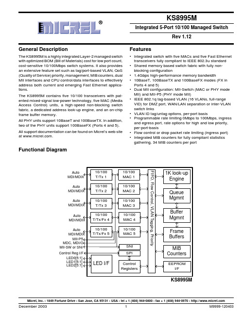
General DescriptionThe KS8995M is a highly integrated Layer-2 managed switchwith optimized BOM (Bill of Materials) cost for low port count,cost-sensitive 10/100Mbps switch systems. It also provides an extensive feature set such as tag/port-based VLAN, QoS (Quality of Service) priority, management, MIB counters, dual MII interfaces and CPU control/data interfaces to effectively address both current and emerging Fast Ethernet applica-tions.The KS8995M contains five 10/100 transceivers with pat-ented mixed-signal low-power technology, five MAC (Media Access Control) units, a high-speed non-blocking switch fabric, a dedicated address look-up engine, and an on-chip frame buffer memory.All PHY units support 10BaseT and 100BaseTX. In addition,two of the PHY units support 100BaseFX (Ports 4 and 5).All support documentation can be found on Micrel’s web site at .Features•Integrated switch with five MACs and five Fast Ethernet transceivers fully compliant to IEEE 802.3u standard •Shared memory based switch fabric with fully non-blocking configuration• 1.4Gbps high-performance memory bandwidth•10BaseT, 100BaseTX and 100BaseFX modes (FX in Ports 4 and 5)•Dual MII configuration: MII-Switch (MAC or PHY mode MII) and MII-P5 (PHY mode MII)•IEEE 802.1q tag-based VLAN (16 VLANs, full-range VID) for DMZ port, WAN/LAN separation or inter-VLAN switch links•VLAN ID tag/untag options, per-port basis•Programmable rate limiting 0Mbps to 100Mbps, ingress and egress port, rate options for high and low priority,per-port-basis•Flow control or drop packet rate limiting (ingress port)•Integrated MIB counters for fully compliant statistics gathering, 34 MIB counters per portMicrel, Inc. • 1849 Fortune Drive • San Jose, CA 95131 • USA • tel + 1 (408) 944-0800 • fax + 1 (408) 944-0970 • Functional DiagramAuto Auto Auto Auto Auto KS8995MFeatures (continued)•Enable/Disable option for huge frame size up to 1916 bytes per frame•IGMP v1/v2 snooping for multicast packet filtering •Special tagging mode to send CPU info on ingress packet’s port value•SPI slave (complete) and MDIO (MII PHY only) serial management interface for control of register configura-tion•MAC-id based security lock option•Control registers configurable on-the-fly (port-priority, 802.1p/d/q, AN...)•CPU read access to MAC forwarding table entries •802.1d Spanning Tree Protocol•Port mirroring/monitoring/sniffing:ingress and/or egress traffic to any port or MII•Broadcast storm protection with percent control–global and per-port basis•Optimization for fiber-to-copper media conversion •Full-chip hardware power-down support (register configuration not saved)•Per-port based software power-save on PHY (idle link detection, register configuration preserved)•QoS/CoS packets prioritization supports: per port, 802.1p and DiffServ based•802.1p/q tag insertion or removal on a per port basis (egress)•MDC and MDI/O interface support to access the MII PHY control registers (not all control registers)•MII local loopback support•On-chip 64Kbyte memory for frame buffering (not shared with 1K unicast address table)•Wire-speed reception and transmission•Integrated look-up engine with dedicated 1K MAC addresses•Full duplex IEEE 802.3x and half-duplex back pressure flow control•Comprehensive LED support•7-wire SNI support for legacy MAC interface •Automatic MDI/MDI-X crossover for plug-and-play •Disable Automatic MDI/MDI-X option•Low power:Core:1.8VI/O:2.5V or 3.3V•0.18µm CMOS technology•Commercial temperature range:0°C to +70°C •Industrial temperature range:–40°C to +85°C •Available in 128-pin PQFP package Applications•Broadband gateway/firewall/VPN•Integrated DSL or cable modem multi-port router •Wireless LAN access point plus gateway•Home networking expansion•Standalone 10/100 switch•Hotel/campus/MxU gateway•Enterprise VoIP gateway/phone•FTTx customer premise equipment•Managed media converterOrdering InformationPart Number Temperature Range PackageKS8995M0°C to +70°C128-Pin PQFPKSZ8995M0°C to +70°C128-Pin PQFP Lead Free KS8995MI–40°C to +85°C128-Pin PQFPRevision HistoryRevision Date Summary of Changes1.0011/05/01Created1.0111/09/01Pinout Mux1/2, DVCC-IO2.5/3.3V, feature list, register spec 11-091.0212/03/01Editorial changes, added new register and MIB descriptions. Added paragraph describing TOS registers.Imported functional descriptions. Formatting.1.0312/12/01Incorporate changes per engineering feedback as well as updating functional descriptions and addingnew timing information.1.0412/13/01Changed Rev. and For. Modes to PHY and MAC modes respectively. Added MIIM clarification in “MIIManagement Interface” section. Reformatted section sequence. Added hex register addresses. Addedadvertisement ability descriptions.1.0512/18/01Inserted switch forwarding flow charts.1.0612/20/01Added new KS8995M block diagram, editorial changes, register descriptions changes and cross-references from functional descriptions to register and strap in options.1.071/22/01Changed FXSD pins to inputs, added new descriptions to “Configuration Interfaces” section.Edited pin descriptions.1.083/1/02Editorial changes in “Dynamic MAC Address table and “MIB Counters.” Updated figure 2 flowchart.Updated table 2 for MAC mode connections. Separate static MAC bit assignments for read and write.Edited read and write examples to MAC tables and MIB counters. Changed Table 3 KS8995M signals to“S” suffix. Changed aging description in Register 2, bit 0. Changed “Port Registers” section and listed allport register addresses. Changed port control 11 description for bits [7:5]. Changed MIB counterdescriptions.1.095/17/02Changed MII setting in “Pin Descriptions.” Changed pu/pd descriptions for SMRXD2. “Register 18,”changed pu/pd description for forced flow control. “Illegal Frames. ” Edited large packet sizes back in.“Elecrical Characteristics,” Added in typical supply current numbers for 100 BaseTX and 10 BaseTXoperation. “Register 18,” Added in note for illegal half-duplex, force flow control. “Pin Description,” Addedextra X1 clock input description. “Elecrical Characteristics,” Updated to chip only current numbers.Added SPI Timing. Feature Highlights.1.107/29/02“Pin Description,” changed SMRXC and SMTXC to I/O. Input in MAC mode, output in PHY mode MII.“Elecrical Characteristics,” modified current consumption to chip only numbers. “Half-Duplex BackPressure,” added description for no dropped packets in half-duplex mode. Added recommendedoperating conditions. Added Idle mode current consumption in “Elecrical Characteristics,” added“Selection of Isolation Transformers,” Added 3.01kΩ resistor instructions for ISET “Pin Description”section. Changed Polarity of transmit pairs in “Pin Description.” Changed description for Register 2, bit 1,in “Register Description” section. Added “Reset Timing” section.1.1112/17/02“Register 3” changed 802.1x to 802.3x. “Register 6,” changed default column to disable flow control forpull-down, and enable flow control for pull-up. “Register 29” and “Register 0” indicate loop back is at thePHY. Added description to register 4 bit 2 to indicate that STPID packets from CPU to normal ports arenot allowed as 1522 byte tag packets. Fixed dynamic MAC address example errors in “Dynamic MACAddress Table.” Changed definition of forced MDI, MDIX in section “Register 29,”“Register 30” and“Register 0.” Added “Part Ordering Information.” Added Ambient operating temperature for KS8995MI 1.123/10/03Changed pin 120 description to NC. Changed SPIQ pin description to Otri. Changed logo. Changedcontact information.Table of ContentsSystem Level Applications (7)Pin Description (by Number) (9)Pin Description (by Name) (15)Pin Configuration (21)Introduction (22)Functional Overview:Physical Layer Transceiver (22)100BaseTX Transmit (22)100BaseTX Receive (22)PLL Clock Synthesizer (22)Scrambler/De-scrambler (100BaseTX only) (22)100BaseFX Operation (22)100BaseFX Signal Detection (22)100BaseFX Far End Fault (23)10BaseT Transmit (23)10BaseT Receive (23)Power Management (23)MDI/MDI-X Auto Crossover (23)Auto-Negotiation (23)Functional Overview:Switch Core (24)Address Look-Up (24)Learning (24)Migration (24)Aging (24)Forwarding (24)Switching Engine (24)MAC Operation (24)Inter-Packet Gap (IPG) (24)Backoff Algorithm (24)Late Collision (26)Illegal Frames (26)Flow Control (26)Half-Duplex Back Pressure (26)Broadcast Storm Protection (26)MII Interface Operation (26)SNI Interface Operation (28)Advanced Functionality (28)Spanning Tree Support (28)Special Tagging Mode (29)IGMP Support (30)Port Mirroring Support (31)VLAN Support (31)Rate Limit Support (32)Configuration Interface (33)I2C Master Serial Bus Configuration (35)SPI Slave Serial Bus Configuration (35)MII Management Interface (MIIM) (38)Register Description (39)Global Registers (39)Register 0 (0x00): Chip ID0 (39)Register 1 (0x01): Chip ID1/Start Switch (39)Register 2 (0x02): Global Control 0 (40)Register 3 (0x03): Global Control 1 (40)Register 4 (0x04): Global Control 2 (41)Register 5 (0x05): Global Control 3 (42)Register 6 (0x06): Global Control 4 (42)Register 7 (0x07): Global Control 5 (43)Register 8 (0x08): Global Control 6 (43)Register 9 (0x09): Global Control 7 (43)Register 10 (0x0A): Global Control 8 (43)Register 11 (0x0B): Global Control 9 (43)Port Registers (44)Register 16 (0x10):Port 1 Control 0 (44)Register 17 (0x11):Port 1 Control 1 (44)Register 18 (0x12):Port 1 Control 2 (45)Register 19 (0x13):Port 1 Control 3 (46)Register 20 (0x14):Port 1 Control 4 (46)Register 21 (0x15):Port 1 Control 5 (46)Register 22 (0x16):Port 1 Control 6 (46)Register 23 (0x17):Port 1 Control 7 (46)Register 24 (0x18):Port 1 Control 8 (47)Register 25 (0x19):Port 1 Control 9 (47)Register 26 (0x1A):Port 1 Control 10 (47)Register 27 (0x1B):Port 1 Control 11 (47)Register 28 (0x1C):Port 1 Control 12 (48)Register 29 (0x1D):Port 1 Control 13 (49)Register 30 (0x1E):Port 1 Status 0 (49)Register 31 (0x1F):Port 1 Status 1 (50)Advanced Control Registers (50)Register 96 (0x60):TOS Priority Control Register 0 (50)Register 97 (0x61):TOS Priority Control Register 1 (50)Register 98 (0x62):TOS Priority Control Register 2 (50)Register 99 (0x63):TOS Priority Control Register 3 (50)Register 100 (0x64):TOS Priority Control Register 4 (50)Register 101 (0x65):TOS Priority Control Register 5 (50)Register 102 (0x66):TOS Priority Control Register 6 (50)Register 103 (0x67):TOS Priority Control Register 7 (50)Register 104 (0x68):MAC Address Register 0 (50)Register 105 (0x69):MAC Address Register 1 (50)Register 106 (0x6A):MAC Address Register 2 (50)Register 107 (0x6B):MAC Address Register 3 (50)Register 108 (0x6C):MAC Address Register 4 (50)Register 109 (0X6D):MAC Address Register 5 (50)Register 110 (0x6E):Indirect Access Control 0 (51)Register 111 (0x6F):Indirect Access Control 1 (51)Register 112 (0x70):Indirect Data Register 8 (51)Register 113 (0x71):Indirect Data Register 7 (51)Register 114 (0x72):Indirect Data Register 6 (51)Register 115 (0x73):Indirect Data Register 5 (51)Register 116 (0x74):Indirect Data Register 4 (51)Register 117 (0x75):Indirect Data Register 3 (51)Register 118 (0x76):Indirect Data Register 2 (51)Register 119 (0x77):Indirect Data Register 1 (51)Register 120 (0x78):Indirect Data Register 0 (51)Register 121 (0x79):Digital Testing Status 0 (51)Register 122 (0x7A):Digital Testing Status 1 (51)Register 123 (0x7B):Digital Testing Control 0 (51)Register 124 (0x7C):Digital Testing Control 1 (51)Register 125 (0x7D):Analog Testing Control 0 (51)Register 126 (0x7E):Analog Testing Control 1 (52)Register 127 (0x7F):Analog Testing Status (52)Static MAC Address (53)VLAN Address (55)Dynamic MAC Address (56)MIB Counters (57)MIIM Registers (60)Register 0: MII Control (60)Register 1: MII Status (61)Register 2: PHYID HIGH (61)Register 3: PHYID LOW (61)Register 4: Advertisement Ability (61)Register 5: Link Partner Ability (62)Absolute Maximum Ratings (63)Operating Ratings (63)Electrical Characteristics (63)Timing Diagrams (65)Selection of Isolation Transformers (72)Qualified Magnetic Lists (72)Package Information (73)System Level Applications4-port LAN1-portWAN I/FFigure 1.Broadband Gateway4-port LANFigure 2.Integrated Broadband Router5-port LANFigure 3.Standalone SwitchPin Description (by Number)Pin Number Pin Name Type(1)Port Pin Function1TEST1NC NC for normal operation. Factory test pin.2GNDA Gnd Analog ground3VDDAR P 1.8V analog V DD4RXP1I1Physical receive signal + (differential)5RXM1I1Physical receive signal - (differential)6GNDA Gnd Analog ground7TXM1O1Physical transmit signal - (differential)8TXP1O1Physical transmit signal + (differential)9VDDAT P 2.5V analog V DD10RXP2I2Physical receive signal + (differential)11RXM2I2Physical receive signal - (differential)12GNDA Gnd Analog ground13TXM2O2Physical transmit signal - (differential)14TXP2O2Physical transmit signal + (differential)15VDDAR P 1.8V analog V DD16GNDA Gnd Analog ground17ISET Set physical transmit output current. Pull-down with a 3.01kΩ 1%resistor.18VDDAT P 2.5V analog V DD19RXP3I3Physical receive signal + (differential)20RXM3I3Physical receive signal - (differential)21GNDA Gnd Analog ground22TXM3O3Physical transmit signal - (differential)23TXP3O3Physical transmit signal + (differential)24VDDAT P 2.5V analog V DD25RXP4I4Physical receive signal + (differential)26RXM4I4Physical receive signal - (differential)27GNDA Gnd Analog ground28TXM4O4Physical transmit signal - (differential)29TXP4O4Physical transmit signal + (differential)30GNDA Gnd Analog ground31VDDAR P 1.8V analog V DDNote:1.P = Power supplyI = InputO = OutputI/O = Bi-directionalGnd = GroundIpu = Input w/ internal pull-upIpd = Input w/ internal pull-downIpd/O = Input w/ internal pull-down during reset, output pin otherwiseIpu/O = Input w/ internal pull-up during reset, output pin otherwisePU = Strap pin pull-upPD = Strap pin pull-downOtri = Output tristatedNC = No ConnectPin Number Pin Name Type(1)Port Pin Function32RXP5I5Physical receive signal + (differential)33RXM5I5Physical receive signal - (differential)34GNDA Gnd Analog ground35TXM5O5Physical transmit signal - (differential)36TXP5O5Physical transmit signal + (differential)37VDDAT P 2.5V analog V DD38FXSD5I5Fiber signal detect/factory test pin39FXSD4I4Fiber signal detect/factory test pin40GNDA Gnd Analog ground41VDDAR P 1.8V analog V DD42GNDA Gnd Analog ground43VDDAR P 1.8V analog V DD44GNDA Gnd Analog ground45MUX1NC MUX1 and MUX2 should be left unconnected for normal operation.46MUX2NC They are factory test pins.Mode Mux1Mux2Normal Operation NC NCRemote Analog Loopback Mode for Testing only01Reserved10Power Save Mode for Testing only11 47PWRDN_N Ipu Full-chip power down. Active low.48RESERVE NC Reserved pin. No connect.49GNDD Gnd Digital ground50VDDC P 1.8V digital core V DD51PMTXEN Ipd5PHY[5] MII transmit enable52PMTXD3Ipd5PHY[5] MII transmit bit 353PMTXD2Ipd5PHY[5] MII transmit bit 254PMTXD1Ipd5PHY[5] MII transmit bit 155PMTXD0Ipd5PHY[5] MII transmit bit 056PMTXER Ipd5PHY[5] MII transmit error57PMTXC O5PHY[5] MII transmit clock. PHY mode MII.58GNDD Gnd Digital groundNote:1.P = Power supplyI = InputO = OutputI/O = Bi-directionalGnd = GroundIpu = Input w/ internal pull-upIpd = Input w/ internal pull-downIpd/O = Input w/ internal pull-down during reset, output pin otherwiseIpu/O = Input w/ internal pull-up during reset, output pin otherwisePU = Strap pin pull-upPD = Strap pin pull-downOtri = Output tristatedNC = No ConnectPin Number Pin Name Type(1)Port Pin Function59VDDIO P 3.3/2.5V digital V DD for digital I/O circuitry60PMRXC O5PHY[5] MII receive clock. PHY mode MII61PMRXDV Ipd/O5PHY[5] MII receive data valid62PMRXD3Ipd/O5PHY[5] MII receive bit 3. Strap option:PD (default) = enable flowcontrol; PU = disable flow control.63PMRXD2Ipd/O5PHY[5] MII receive bit 2. Strap option:PD (default) = disable backpressure; PU = enable back pressure.64PMRXD1Ipd/O5PHY[5] MII receive bit 1. Strap option:PD (default) = drop excessivecollision packets; PU = does not drop excessive collision packets.65PMRXD0Ipd/O5PHY[5] MII receive bit 0. Strap option: PD (default) = disableaggressive back-off algorithm in half-duplex mode; PU = enable forperformance enhancement.66PMRXER Ipd/O5PHY[5] MII receive error. Strap option:PD (default) = 1522/1518 bytes;PU = packet size up to 1536 bytes.67PCRS Ipd/O5PHY[5] MII carrier sense/Force duplex mode. See “Register 76” forport 4 only. PD (default) = Force half-duplex if auto-negotiation isdisabled or fails. PU = Force full-duplex if auto-negotiation is disabledor fails.68PCOL Ipd/O5PHY[5] MII collision detect/ Force flow control. See “Register 66” forport 4 only. PD (default) = No force flow control. PU = Force flowcontrol.69SMTXEN Ipd Switch MII transmit enable70SMTXD3Ipd Switch MII transmit bit 371SMTXD2Ipd Switch MII transmit bit 272SMTXD1Ipd Switch MII transmit bit 173SMTXD0Ipd Switch MII transmit bit 074SMTXER Ipd Switch MII transmit error75SMTXC I/O Switch MII transmit clock. Input in MAC mode, output in PHY mode MII.76GNDD Gnd Digital ground77VDDIO P 3.3/2.5V digital V DD for digital I/O circuitry78SMRXC I/O Switch MII receive clock. Input in MAC mode, output in PHY mode MII.79SMRXDV Ipd/O Switch MII receive data valid80SMRXD3Ipd/O Switch MII receive bit 3. Strap option: PD (default) = Disable Switch MIIfull-duplex flow control; PU = Enable Switch MII full-duplex flow control.81SMRXD2Ipd/O Switch MII receive bit 2. Strap option: PD (default) = Switch MII in full-duplex mode; PU = Switch MII in half-duplex mode.Note:1.P = Power supplyI = InputO = OutputI/O = Bi-directionalGnd = GroundIpu = Input w/ internal pull-upIpd = Input w/ internal pull-downIpd/O = Input w/ internal pull-down during reset, output pin otherwiseIpu/O = Input w/ internal pull-up during reset, output pin otherwisePU = Strap pin pull-upPD = Strap pin pull-downOtri = Output tristatedNC = No ConnectPin Number Pin Name Type(1)Port Pin Function82SMRXD1Ipd/O Switch MII receive bit 1. Strap option: PD (default) = Switch MII in100Mbps mode; PU = Switch MII in 10Mbps mode.83SMRXD0Ipd/O Switch MII receive bit 0; Strap option: LED ModePD (default) = Mode 0; PU = Mode 1. See “Register 11.”Mode 0Mode 1LEDX_2Lnk/Act100Lnk/ActLEDX_1Fulld/Col10Lnk/ActLEDX_0Speed Fulld 84SCOL Ipd/O Switch MII collision detect85SCRS Ipd/O Switch MII carrier sense86SCONF1Ipd Dual MII configuration pinPin# (91, 86, 87):Switch MII PHY [5] MII000Disable, Otri Disable, Otri001PHY Mode MII Disable, Otri010MAC Mode MII Disable, Otri011PHY Mode SNI Disable, Otri100Disable Disable101PHY Mode MII PHY Mode MII110MAC Mode MII PHY Mode MII111PHY Mode SNI PHY Mode MII 87SCONF0Ipd Dual MII configuration pin88GNDD Gnd Digital ground89VDDC P 1.8V digital core V DD90LED5-2Ipu/O5LED indicator 2. Strap option: Aging setup. See “Aging” sectionPU (default) = Aging Enable; PD = Aging disable.91LED5-1Ipu/O5LED indicator 1. Strap option: PU (default): enable PHY MII I/FPD:tristate all PHY MII output. See “pin# 86 SCONF1.”92LED5-0Ipu/O5LED indicator 093LED4-2Ipu/O4LED indicator 294LED4-1Ipu/O4LED indicator 195LED4-0Ipu/O4LED indicator 096LED3-2Ipu/O3LED indicator 297LED3-1Ipu/O3LED indicator 1Note:1.P = Power supplyI = InputO = OutputI/O = Bi-directionalGnd = GroundIpu = Input w/ internal pull-upIpd = Input w/ internal pull-downIpd/O = Input w/ internal pull-down during reset, output pin otherwiseIpu/O = Input w/ internal pull-up during reset, output pin otherwisePU = Strap pin pull-upPD = Strap pin pull-downOtri = Output tristatedNC = No ConnectPin Number Pin Name Type(1)Port Pin Function98LED3-0Ipu/O3LED indicator 099GNDD Gnd Digital ground100VDDIO P 3.3/2.5V digital V DD for digital I/O101LED2-2Ipu/O2LED indicator 2102LED2-1Ipu/O2LED indicator 1103LED2-0Ipu/O2LED indicator 0104LED1-2Ipu/O1LED indicator 2105LED1-1Ipu/O1LED indicator 1106LED1-0Ipu/O1LED indicator 0107MDC Ipu All Switch or PHY[5] MII management data clock108MDIO I/O All Switch or PHY[5] MII management data I/O.Features internal pull down to define pin state when not driven.109SPIQ Otri All(1) SPI serial data output in SPI slave mode; (2) Not used in I2C mastermode. See “pin# 113.”110SPIC/SCL I/O All(1) Input clock up to 5MHz in SPI slave mode; (2) Output clock at81KHz in I2C master mode. See “pin# 113.”111SPID/SDA I/O All(1) Serial data input in SPI slave mode; (2) Serial data input/output inI2C master mode See “pin# 113.”112SPIS_N Ipu All Active low. (1) SPI data transfer start in SPI slave mode. When SPIS_Nis high, the KS8995M is deselected and SPIQ is held in high impedancestate, a high-to-low transition to initiate the SPI data transfer; (2) Notused in I2C master mode.113PS1Ipd Serial bus configuration pinIf EEPROM is not present, the KS8995M will start itself with chipdefault (00)...Pin Config.Serial Bus ConfigurationPS[1:0]=00I2C Master Mode for EEPROMPS[1:0]=01ReservedPS[1:0]=10SPI Slave Mode for CPU InterfacePS[1:0]=11Factory Test Mode (BIST) 114PS0Ipd Serial bus configuration pin. See “pin# 113.”115RST_N Ipu Reset the KS8995M. Active low.116GNDD Gnd Digital ground117VDDC P 1.8V digital core V DD118TESTEN Ipd NC for normal operation. Factory test pin.Note:1.P = Power supplyI = InputO = OutputI/O = Bi-directionalGnd = GroundIpu = Input w/ internal pull-upIpd = Input w/ internal pull-downIpd/O = Input w/ internal pull-down during reset, output pin otherwiseIpu/O = Input w/ internal pull-up during reset, output pin otherwisePU = Strap pin pull-upPD = Strap pin pull-downOtri = Output tristatedNC = No ConnectPin Number Pin Name Type(1)Port Pin Function119SCANEN Ipd NC for normal operation. Factory test pin.120NC NC No Connect121X1I25MHz crystal clock connection/or 3.3V tolerant oscillator input.Oscillator should be ±100ppm.122X2O25MHz crystal clock connection123VDDAP P 1.8V analog V DD for PLL124GNDA Gnd Analog ground125VDDAR P 1.8V analog V DD126GNDA Gnd Analog ground127GNDA Gnd Analog ground128TEST2NC NC for normal operation. Factory test pin.Note:1.P = Power supplyI = InputO = OutputI/O = Bi-directionalGnd = GroundIpu = Input w/ internal pull-upIpd = Input w/ internal pull-downIpd/O = Input w/ internal pull-down during reset, output pin otherwiseIpu/O = Input w/ internal pull-up during reset, output pin otherwisePU = Strap pin pull-upPD = Strap pin pull-downOtri = Output tristatedNC = No ConnectPin Description (by Name)Pin Number Pin Name Type(1)Port Pin Function39FXSD4I4Fiber signal detect/factory test pin.38FXSD5I5Fiber signal detect/factory test pin.124GNDA Gnd Analog ground42GNDA Gnd Analog ground44GNDA Gnd Analog ground2GNDA Gnd Analog ground16GNDA Gnd Analog ground30GNDA Gnd Analog ground6GNDA Gnd Analog ground12GNDA Gnd Analog ground21GNDA Gnd Analog ground27GNDA Gnd Analog ground34GNDA Gnd Analog ground40GNDA Gnd Analog ground120NC NC No connect127GNDA Gnd Analog ground126GNDA Gnd Analog ground49GNDD Gnd Digital ground88GNDD Gnd Digital ground116GNDD Gnd Digital ground58GNDD Gnd Digital ground76GNDD Gnd Digital ground99GNDD Gnd Digital ground17ISET Set physical transmit output current. Pull-down with a 3.01kΩ 1%resistor.106LED1-0Ipu/O1LED indicator 0105LED1-1Ipu/O1LED indicator 1104LED1-2Ipu/O1LED indicator 2103LED2-0Ipu/O2LED indicator 0102LED2-1Ipu/O2LED indicator 1101LED2-2Ipu/O2LED indicator 298LED3-0Ipu/O3LED indicator 0Note:1.P = Power supplyI = InputO = OutputI/O = Bi-directionalGnd = GroundIpu = Input w/ internal pull-upIpd = Input w/ internal pull-downIpd/O = Input w/ internal pull-down during reset, output pin otherwiseIpu/O = Input w/ internal pull-up during reset, output pin otherwisePU = Strap pin pull-upPD = Strap pin pull-downOtri = Output tristatedNC = No ConnectPin Number Pin Name Type(1)Port Pin Function97LED3-1Ipu/O3LED indicator 196LED3-2Ipu/O3LED indicator 295LED4-0Ipu/O4LED indicator 094LED4-1Ipu/O4LED indicator 193LED4-2Ipu/O4LED indicator 292LED5-0Ipu/O5LED indicator 091LED5-1Ipu/O5LED indicator 1. Strap option:PU (default): enable PHY MII I/F.PD:tristate all PHY MII output. See “pin# 86 SCONF1.”90LED5-2Ipu/O5LED indicator 2. Strap option: Aging setup. See “Aging” section.(default) = Aging Enable;PD = Aging disable 107MDC Ipu All Switch or PHY[5] MII management data clock.108MDIO I/O All Switch or PHY[5] MII management data I/O.1TEST1NC NC for normal operation. Factory test pin.45MUX1NC MUX1 and MUX2 should be left unconnected for normal operation.46MUX2NC They are factory test pins.Mode Mux1Mux2Normal Operation NC NCRemote Analog Loopback Mode for Testing only01Reserved10Power Save Mode for Testing only11 68PCOL Ipd/O5PHY[5] MII collision detect/Force flow control. See “Register 18.”For port 4 only. PD (default) = No force flow control. PU = Force flowcontrol.67PCRS Ipd/O5PHY[5] MII carrier sense/Force duplex mode See “Register 28.”For port 4 only. PD (default) = Force half-duplex if auto-negotiation isdisabled or fails. PU = Force full-duplex if auto-negotiation is disabledor fails.60PMRXC O5PHY[5] MII receive clock. PHY mode MII.65PMRXD0Ipd/O5PHY[5] MII receive bit 0. Strap option: PD (default) = disableaggressive back-off algorithm in half-duplex mode; PU = enable forperformance enhancement.64PMRXD1Ipd/O5PHY[5] MII receive bit 1. Strap option: PD (default) = drop excessivecollision packets; PU = does not drop excessive collision packets.63PMRXD2Ipd/O5PHY[5] MII receive bit 2. Strap option: PD (default) = disable backpressure; PU = enable back pressure.62PMRXD3Ipd/O5PHY[5] MII receive bit 3. Strap option: PD (default) = enable flowcontrol; PU = disable flow control.Note:1.P = Power supplyI = InputO = OutputI/O = Bi-directionalGnd = GroundIpu = Input w/ internal pull-upIpd = Input w/ internal pull-downIpd/O = Input w/ internal pull-down during reset, output pin otherwiseIpu/O = Input w/ internal pull-up during reset, output pin otherwisePU = Strap pin pull-upPD = Strap pin pull-downOtri = Output tristatedNC = No Connect。

it面试题库及答案IntroductionWith the rapid development of information technology, the demand for IT professionals has been increasing. As a result, IT interviews have become a crucial step in the hiring process. To succeed in an IT interview, it is essential to have a comprehensive understanding of commonly asked questions and well-prepared answers. This article aims to provide a detailed IT interview question bank along with sample answers.1. Technical Questions1.1 Programming Languages1.1.1 What is the difference between Java and Python?Java and Python are both popular programming languages but differ in various aspects. Java is a compiled language that runs on the Java Virtual Machine (JVM), while Python is an interpreted language. Java is mainly used for enterprise-level applications, while Python is known for its simplicity and readability. Additionally, Java requires explicit declaration of data types, while Python uses dynamic typing.1.1.2 What is object-oriented programming?Object-oriented programming (OOP) is a programming paradigm that organizes software design around objects that represent real-world entities. It emphasizes the concepts of encapsulation, inheritance, and polymorphism. OOP allows for modular and reusable code, making it easier to maintain and expand software systems.1.2 Database Management1.2.1 What is the difference between SQL and NoSQL databases?SQL (Structured Query Language) databases are relational databases that store and manage structured data in tables with predefined schemas. They are suitable for complex queries and transactions. NoSQL (Not only SQL) databases, on the other hand, are non-relational databases designed for handling large amounts of unstructured or semi-structured data. They provide flexible schemas and horizontal scalability.1.2.2 What is ACID in database management?ACID (Atomicity, Consistency, Isolation, Durability) is a set of properties that ensure reliability and consistency in database transactions. Atomicity guarantees that a transaction is treated as a single unit of work, either fully completed or fully rolled back if any part fails. Consistency ensures that the database remains in a valid state before and after a transaction. Isolation prevents interference from concurrent transactions, and Durability guarantees that once a transaction is committed, its changes are permanent.2. Behavioral Questions2.1 Problem-Solving2.1.1 Describe a challenging technical problem you encountered and how you resolved it.2.1.2 Give an example of a time when you had to work under pressure to meet a tight deadline. How did you handle it?2.2 Communication Skills2.2.1 Explain a complex technical concept to someone without a technical background.2.2.2 Describe a situation where you had to communicate and collaborate with a team to solve a problem.3. Sample Answers1.1.1 Java and Python differ in their execution models and use cases. Java is a compiled language that runs on the JVM, allowing for high performance and platform independence. It is commonly used for building enterprise-level applications. In contrast, Python is an interpreted language known for its simplicity and readability. It is widely adopted in web development, scientific computing, and data analysis due to its ease of use and extensive library support.1.1.2 Object-oriented programming (OOP) is a software development paradigm that focuses on modular and reusable code. It organizes software design around objects, which are instances of classes representing real-world entities. OOP emphasizes encapsulation, where data and methods are bundled together within objects. It also enables inheritance, allowing classes to inherit attributes and behaviors from parent classes. Polymorphism, another key concept in OOP, allows objects to take on many forms and exhibit different behaviors based on the context. OOP enhances code reusability, maintainability, and scalability.2.1.1 In my previous role, I encountered a challenging technical problem where a critical database server went down, causing a major disruption inour production environment. I promptly identified the root cause, which was a disk failure. To resolve the issue, I replaced the faulty disk and restored the database from the latest backup. However, to minimize the downtime, I implemented a backup server configuration and utilized a replication mechanism to keep the data synchronized. This solution ensured both data integrity and high availability.2.1.2 Working under pressure to meet tight deadlines is a common occurrence in the IT industry. In one instance, I received a project with an unexpectedly shortened timeline due to unexpected client requirements. To handle the situation, I immediately prioritized the tasks, focusing on critical components and breaking down the project into manageable subtasks. I communicated with the team, delegating responsibilities and ensuring everyone was aware of the new timeline. By working overtime, maintaining constant communication, and efficiently managing resources, we successfully met the deadline without compromising the quality of the deliverables.2.2.1 Complex technical concepts can be challenging to explain to non-technical individuals. To overcome this, I often use analogies and relatable examples to help them grasp the idea. For instance, when explaining encryption, I compare it to sending secret messages using a lock and key. I describe how encryption algorithms scramble data (message) using a key (like a lock), making it unreadable to unauthorized parties. Only someone with the correct key can decrypt (unlock) and access the original message. This simplifies the concept and allows non-technical individuals to understand the fundamentals of encryption.2.2.2 Collaboration and effective communication are vital in solving complex technical problems. In a recent project, our team encountered a challenging software bug that affected the system's stability. To overcome this, we organized regular meetings to discuss and share ideas. Each team member had a specialized area of expertise, so we collaborated closely, actively listening to each other's suggestions and insights. By pooling our knowledge and skills, we successfully identified the root cause and implemented a comprehensive solution. This experience highlighted the importance of teamwork and effective communication in problem-solving.ConclusionThe field of information technology is vast and evolving, and IT interviews are designed to evaluate candidates' technical knowledge, problem-solving abilities, and communication skills. By familiarizing yourself with common IT interview questions and crafting thoughtful answers, you can increase your chances of success. Remember to adapt your answers based on your own experience and expertise. Good luck with your upcoming IT interviews!。

Installation InstructionsY-Series Brushless Servo MotorCatalog Number Y-1002-1, Y-1002-2, Y-1003-1, Y-1003-2, Y-2006-1, Y-2006-2,Y-2012-1, Y-2012-2, and Y-3023-2These installation instructions describe how to install the Y-Series motors. Use this document if you are responsible for designing, installing, or troubleshooting the Allen-Bradley Y-Series motor products. Read all instructions before installing this motor.For: See Page Important User Information2 Receiving and Maintenance Information3Motor Catalog Number Identification3Before You Install the Motor4Using Couplings and Pulleys5Preventing Electrical Noise6Building and Installing Cables7Installing Your Motor8Guidelines for Installation9Mounting Dimensions10 Connector Data13Motor Load Force Ratings14Radial Load and Axial Load Force Ratings15Cables and Connector Kits152 Y-Series Motor Installation InstructionsImportant User InformationSolid state equipment has operational characteristics differing from those of electromechanical equipment. Safety Guidelines for the Application, Installation and Maintenance of Solid State Controls, publication SGI-1.1, is available from your local Rockwell Automation sales office or online at) describes some important differences between solid state equipment and hard-wired electromechanical devices. Because of this difference, and also because of the wide variety of uses for solid state equipment, all persons responsible for applying this equipment must satisfy themselves that each intended application of this equipment is acceptable.In no event will Rockwell Automation, Inc. be responsible or liable for indirect or consequential damages resulting from the use or application of this equipment.The examples and diagrams in this manual are included solely for illustrative purposes. Because of the many variables and requirements associated with any particular installation, Rockwell Automation, Inc. cannot assume responsibility or liability for actual use based on the examples and diagrams.No patent liability is assumed by Rockwell Automation, Inc. with respect to use of information, circuits, equipment, or software described in this manual.Reproduction of the contents of this manual, in whole or in part, without written permission of Rockwell Automation, Inc., is prohibited.Throughout this manual, when necessary, we use notes to make you aware of safety considerations.Y-Series Motor Installation Instructions 3 Receiving and Maintenance InformationThe customer is responsible for inspecting the equipment before accepting the shipment from the freight company. Check the item(s) you receive against your purchase order.Maintain your motor within the following environmental conditions:•in a clean, dry location•within the operating temperature range, 0° to 40° C (32° to 104° F)•within the storage temperature range, -30° to 70° C (-22° to 158° F)•within the relative humidity range, 5% to 95% non-condensing •in an non-corrosive atmosphereMotor Catalog Number IdentificationY - 2006 - 2 H 00 AAFACTORY DESIGNATED OPTIONSAA StandardOPTIONS00Standard0424V dc BrakeOPTICAL ENCODER LINE COUNTH2000 StandardMOTOR WINDING Ke DESIGNATOR1115V ac2230V acFRAME SIZESERIES DESIGNATORY Light Industrial4 Y-Series Motor Installation InstructionsBefore You Install the MotorBefore installing or storing the motor:1. Remove the motor carefully from its shipping container.2. Visually inspect the motor for any damage.3. Examine the motor frame, front output shaft, and mounting pilotfor any defects.4. Notify the carrier of any shipping damage immediately.Do not open or attempt to open the motor.Only a qualified Allen-Bradley employee canservice this type of motorFailure to observe these safety procedures couldresult in the equipment being damaged.Y-Series Motor Installation Instructions 5 Using Couplings and PulleysMechanical connections to the motor shaft, such as couplings and pulleys, require a torsionally rigid coupling or a reinforced timing belt. The high dynamic performance of servo motors can cause couplings, pulleys or belts to loosen or slip over time. A loose or slipping connection will cause system instability and may damage the motor shaft. All connections between the system and the servo motor shaft must be rigid to achieve acceptable response from the system. Periodically inspect connections to verify their rigidity. When mounting couplings or pulleys to the motor shaft, ensure that the connections are properly aligned and that axial and radial loads are within the specifications of the motor. Refer to Motor Load Force Ratings on page 14 for guidelines on how to achieve 20,000 hours of motor bearing life.6 Y-Series Motor Installation InstructionsPreventing Electrical NoiseElectroMagnetic Interference (EMI), commonly called noise, may adversely impact motor performance by inducing stray signals. Effective techniques to counter EMI include filtering the AC power, shielding and separating signal carrying lines, and practicing good grounding techniques.Effective AC power filtering can be achieved by using isolated AC power transformers or properly installed AC line filters.To help avoid EMI:1. Physically separate signal lines from motor cabling and powerwiring. Do not route signal wires with motor and power wires, or over the vent openings of servo drives.2. Ground all equipment using a single-point parallel ground systemthat employs ground bus bars or large straps. If necessary, use additional electrical noise reduction techniques to reduce EMI in noisy environments.Y-Series Motor Installation Instructions 7 Building and Installing CablesKnowledgeable cable routing and careful cable construction improves system ElectroMagnetic Compatibility (EMC).To build and install cables, perform the following steps:1. Keep wire lengths as short as physically possible.2. Route signal cables (encoder, serial, analog) away from motorand power wiring.3. Separate cables by 0.3 m (1 ft) minimum for every 9 m (30 ft) ofparallel run.4. Ground both ends of the encoder cable shield and twist the signalwire pairs to prevent electromagnetic interference (EMI) from other equipment.High voltage can be present on the shield of apower cable, if the shield is not grounded.Ensure there is a connection to ground for anypower cable shield.Failure to observe these safety procedures couldresult in personal injury or damage to equipment.8 Y-Series Motor Installation InstructionsInstalling Your MotorY-2006, Y-2012, and Y-3023 motors include a mounting pilot for aligning the motor on a machine. Preferred fasteners are stainless steel. The installation must comply with all local regulations and use of equipment and installation practices that promote electromagnetic compatibility (EMC) and safety.Unmounted motors, disconnected mechanicalcouplings, and/or disconnected cables aredangerous if power is applied.Disassembled equipment should be appropriatelyidentified (tagged-out) and access to electricalpower restricted (locked-out).Failure to observe these safety procedures couldresult in personal injuryY-Series Motor Installation Instructions 9 Guidelines for InstallationObserve the following for installing the motor.1. Allow sufficient clearances in the area of the motor for it to staywithin its specified operating temperature range. Refer toReceiving and Maintenance Information on page 3 for operating range. Do not enclose the motor unless forced air is blown across the motor for cooling. A fan blowing air across the motor will improve its performance. Keep other heat producing devices away from the motor.2. Refer to Mounting Dimensions on page 10 to determine themounting dimensions of your motor.3. Place the motor with connectors pointing downward.4. Properly mount and align the motor.5. Attach all power and encoder cables after the motor is mountedand use a drip loop in the cable to keep liquids flowing away from the connectors.Outer surfaces of motor can reach hightemperatures, 100° C (212° F) during motoroperation.Take precautions to prevent accidental contact withhot surfaces. Consider motor surface temperaturewhen selecting motor mating connections andcables.Failure to observe these safety procedures couldresult in personal injury or damage to equipment.10 Y-Series Motor Installation InstructionsMounting DimensionsThe dimension symbols and actual dimensions of the different models in the Y-Series are referenced in a table on the next page. Figure 1Reference for Mounting DimensionsY-Series Motor Installation Instructions 11Publication 1398-IN518A-EN-P — January 2001Dimension 1 (Refer to drawing)Motor Y-1002 Y-1003 Y-2006 Y-2012 Y-3023 AB mm 3030414152(in.)(1.2)(1.2)(1.6)(1.6)(2.0)AH mm 2525303040(in.)(1.0)(1.0)(1.2)(1.2)(1.6)AJ mm 4646707090(in.)(1.8)(1.8)(2.8)(2.8)(3.5)AK mm 3030505070(in.)(1.2)(1.2)(2.0)(2.0)(2.8)BB mm 2.5 2.5 3.0 3.0 3.0(in.)(0.10)(0.10)(0.12)(0.12)(0.12)BE mm 55668(in.)(0.2)(0.2)(0.24)(0.24)(0.3)BFmm 4.5 4.5 5.5 5.5 6.6(in.)(0.18)(0.18)(0.22)(0.22)(0.26)BP (3023 only)mm ————2(in.)————(0.8)EP (3023 only)mm ————19.5(in.)————(0.77)Lmm 708895.5123.5140(in.)(2.8)(3.5)(3.8)(4.9)(5.5)L with Brake mm 108.5126.5133.5161.5180.5(in.)(4.27)(4.98)(5.26)(6.36)(7.11)P mm 4040606080(in.)(1.6)(1.6)(2.4)(2.4)(3.1)Umm 88141416(in.)(0.3)(0.3)(0.5)(0.5)(0.6)12 Y-Series Motor Installation InstructionsPublication 1398-IN518A-EN-P — January 2001Shaft End Hole Thread mm ——M5 x 0.8M5 x 0.8M5 x 0.8Shaft End Hole Thread Depth mm ——121212(in.)——(0.5)(0.5)(0.5)TolerancesAH mm ±0.8±0.8±0.8±0.8±0.8(in.)(±0.315)(±0.315)(±0.315)(±0.315)(±0.315)AK mm -0.021-0.021-0.025-0.025-0.030(in.)(-0.0008)(-0.0008)(-0.0009)(-0.0009)(-0.0011)L mm ±1.0±1.0±1.0±1.0±1.0(in.)(±0.4)(±0.4)(±0.4)(±0.4)(±0.4)U mm -0.009-0.009-0.011-0.011-0.011(in.)(-0.0003)(-0.0003)(-0.0004)(-0.0004)(-0.0004)Cab le±100 mm (±4.0 in.)1Y-Series motors are designed to metric dimensions. Inch measurements are mathematical conversions.Dimension 1 (Refer to drawing)MotorY-1002 Y-1003 Y-2006 Y-2012 Y-3023Y-Series Motor Installation Instructions 13Publication 1398-IN518A-EN-P — January 2001Connector DataThe tables below list the signal descriptions for the encoder and power connector pins.Encoder Connector Power Connector Pin Signal Pin Signal 1 - 8, 25-28Open 1Phase R 1 9A+ 2Phase S 1 10A- 3Phase T 1 11B+4Open 12B- 5Ground 13I+ 6Open 14I- 7Brake+ 2 15HALL A+ 8Open 16HALL A- 9Brake- 217HALL B+ 1Cables and drives may label the R, S and T power phases as U, V and W respectively. 2Open on non-brake motors.18HALL B- 19HALL C+ 20HALL C- 21Open 22+5 VDC 23COM 1 24Shield 21+5V COM not connected to motor case ground. 2 Cable Shield connected to motor case ground. Power housing: AMP 206705-2Y-1002/Y-1003 contacts: AMP 66102-8 Y-2006/Y-2012 contacts: AMP 66098-8 Y-3023 contacts: AMP 66098-8Encoder housing: AMP 206152-1Encoder contacts: AMP 3-66507-0321456789121252826348914201514 Y-Series Motor Installation InstructionsMotor Load Force RatingsMotors are capable of operating with sustained maximum radial or maximum axial shaft loads. The measurement points for maximum radial and axial load forces are shown in the figure below.Figure 2Load Forces on ShaftRadial load force (FR) applied to shaft at 2AF/3.The following table represents load factors that provide a 20,000 hour L10 bearing fatigue life for Y-Series motors. These load factors do not account for possible application-specific life reduction factors that may occur, such as bearing grease contamination from external sources.Publication 1398-IN518A-EN-P — January 2001Y-Series Motor Installation Instructions 15 Radial Load and Axial Load Force RatingsMotor Maximum Radial (FR) Load Maximum Axial (F) Loadwith a Radial Loadkg (lb) kg (lb)Y-1002 10(22)3(6.6)Y-1003 10(22)3(6.6)Y-200620(44) 8(17.6)Y-201225(55)10(22.0)Y-302335 (77) 20(44.0)Cables and Connector KitsFactory manufactured cables are available in standard cable lengths. They can provide environmental sealing and shield termination. The following cables are for connecting the Y-Series motors.Catalog Number Description9106-0066Connector Kit(kit includes connector, pins and backshell forboth the power and encoder connectors)Publication 1398-IN518A-EN-P — January 2001Rockwell Automation SupportRockwell Automation provides technical information on the Web to assist you in using its products. At , you can find technical manuals, a knowledge base of FAQs, technical and application notes, sample code and links to software service packs, and a MySupport feature that you can customize to make the best use of these tools.For an additional level of technical phone support for installation, configuration and troubleshooting, we offer TechConnect support programs. For more information, contact your local distributor or Rockwell Automation representative, or visit .Installation AssistanceIf you experience a problem within the first 24 hours of installation, please review the information that's contained in this manual. You can also contact a special Customer Support number for initial help in getting your product up and running. United States 1.440.646.3434Monday – Friday, 8 a.m. – 5 p.m. ESTOutside United States Please contact your local Rockwell Automation representative for any technicalsupport issues.New Product Satisfaction ReturnRockwell Automation tests all of its products to ensure that they are fully operational when shipped from the manufacturing facility. However, if your product is not functioning and needs to be returned, follow these procedures. United States Contact your distributor. You must provide a Customer Support case number (call the phone number above to obtain one) to your distributor in order to complete the returnprocess.Outside United States Please contact your local Rockwell Automation representative for the returnprocedure.Allen-Bradley, Kinetix, Rockwell Automation, MP-Series, and TechConnect are trademarks of Rockwell Automation, Inc. Trademarks not belonging to Rockwell Automation are property of their respective companies.Publication 1398-IN518A-EN-P — January 2001 0013-1064-001 Rev B Supersedes Publication 1398-5.8 April 1999Copyright © Year Rockwell Automation, Inc. All rights reserved. Printed in the U.S.A.。
2017年甘肃省高考英语试题及答案(Word版)2017年甘肃省高考英语试题及答案(Word版)考试时间:120分钟试卷满分:150分)第一部分听力(共两节,满分30分)第二部分阅读理解(共两节,满分40分)第一节(共15小题;每小题2分,满分30分)阅读下列短文,从每题所给的A、B、C、D四个选项中,选出最佳答案。
AIn the coming months。
XXX’s plays in their own language。
in our Globe。
XXX for。
Please come and join us.nal Theatre of China Beijing | ChineseThis great n will be the nal Theatre of China’s first visit to the UK。
The company’s ns show the new face of 21st century Chinese theatre。
This n of Shakespeare’s Richard III will bedirec ted by the nal’s Associate Director。
XXX.Date & Time: Saturday 28 April。
2.30pm & Sunday 29 April。
1.30pm & 6.30pmXXX | ianOne of the most XXX ia。
XXX。
founded in 1928.XXX all over the world。
This new n of As You Like It is helmed by the company’s Artistic Director。
Levan Tsuladze.Date and Time: Friday。
May 18 at 2:30 pm and Sunday。
Fundamentals IChapter1Oracle Architectural Componentsshow sga;alter system set shared_pool_size=64M;alter system set DB_CACHE_SIZE=96M;alter system set large_pool_size=24Mdesc v$db_cache_adviceselect*from v$db_cache_advice;(displayed statistics)Chapter2Getting Started with the Oracle Server1、list the common database administration tools available to a DBAOracle Universal InstallerOracle Database Configuration AssistantPassword File UtilitySQL*PlusOracle Enterprise Manager2、SQL statementscolumn owner format a5;column table_name format a20;column tablespace_name format a15;select owner,table_name,tablespace_name from dba_tables where rownum<10;SQL>!rm$HOME/admin/pfile/orapw$ORACLE_SIDSQL>!orapwd file=$HOME/admin/pflie/orapw$ORACLE_SID password=oracle entries=5SQL>!chmod660$HOME/admin/pfile/orapw$ORACLE_SIDChapter3Managing an Oracle Instance1、create spfile[='spflie-name']from pfile[='pfile-name']for examplecreate spflie='$ORACLE_HOME/dbs/spfilebbk.ora'from pfile='$ORACLE_HOME/dbs/initbbk.ora'; DefaultSQL>create spfile from pfile;SQL>create pflie from spflie;modifying parameters in spfileSQL>alter system set undo_tablespace=undo2;SQL>alter system set undo_tablespace=undo2scope=both;deleting or resetting valuesSQL>alter system reset undo_suppress_errors scope=both sid='*';alter system set parameter_name=parameter_value[comment'text'][scope=memory|spfile|both][sid='sid'|'*'] startup database filestartup pfile=$ORACLE_HOME/dbs/initbbk.orastartup spflie=$ORACLE_HOME/dbs/spfilebbk.orastartup[force][restrict][pfile=filename][open][recover][database][mount][nomount]alter database bbk mount;alter database bbk open read only;alter database{mount|open}alter database open[read write|read only]startup restrictalter system enable restricted session;shutdown[abort|immediate|transactional|normal]alter session set SQL_TRACE=trueChapter4Creating a Databaseorapwd file=$ORACLE_HOME/dbs/orapwU15password=admin entries=5set remote_login_passwordfile=exclusive in initialization parameter fileadd user to the password fileassign appropriate privileges to each userSQL>grant sysdba to heli;Chapter5Using Data Dictionary and Dynamic Performance Viewsselect owner,object_name,object_type from dba_objects;select owner,object_name,object_type from all_objects;select object_name,object_type from user_objects;general overview:dictionary,dict_columnsshcema objects:dba_tables,dba_indexs,dba_tab_columns,dba_constraintsspace allocation:dba_segments,dba_extentsdatabase structure:dba_tablespaces,dba_data_filesdynamic performance examplesv$controlfile:Lists the names of the control filesv$database:Contains database information from the control filev$datafile:Contains data file information from the control filev$instance:Displays the state of the current instancev$parameter:Lists parameter and values currently in effect for the sessioonv$session:Lists session information for each current sessionv$sga:Contains summary information on the system global areav$spparameter:Lists the contents of the SPFILEv$tablespace:Displays tablespace information from the control filev$thread:Contains thread information from the control filev$version:Version numbers of core library components in the Oracle serverselect*from v$fixed_table;7、list of the data dictionary viewsselect table_name from dictionary;8、identify the database name,instance name and size of the database blocksselect name from v$database;select instance from v$thread;select value from v$parameter where name='db_block_size';9、list the name and size the data files,online redo log files,and the name of the control files select name from v$datafile;select member from v$logfile;select name from v$controlfile;10、identify the data file that makes up the system tablespaceselect file_name from dba_data_files where tablespace_name='SYSTEM';11、free space and used spaceselect sum(bytes)/1024"free space in KB"from dba_free_space;select sum(bytes)/1024"used space in KB"from dba_segments;12、list the name and creation date of the database usersselect username,created from dba_users;Chapter6Maintaining the Control Filemultiplexing the control file when using spfilealter system setcontrol_files='$HOME/oracdata/u01/control01.ctl','$HOME/oradata/u02/control02.ctl'scope=spfile;shutdown immediatecp$HOME/oradata/u01/control01.ctl$HOME/oradata/u02/control02.ctlstartup;multiplexing the contril file when using pfileshutdown immediatecp$HOME/oradata/u01/control01.ctl$HOME/oradata/u02/control02.ctlcontrol_files=$HMOE/oradata/u01/control01.ctl,$HOME/oradata/u02/control02.ctlFor exampleSQL>alter system set control_files='/u010g/oradata/bbk/control01.ctl','/u010g/oradata/bbk/control02.ctl','/u010g/oradata/bbk/control03.ctl','/u010g/oradata/bbk/control04.ctl' scope=spfile;SQL>shutdown immediateSQL>!cp/u010g/oradata/bbk/control03.ctl/u010g/oradata/bbk/control04.ctlSQL>!chmod660/u010g/oradata/bbk/control04.ctlSQL>startup;SQL>select*from v$controlfile;4、inital sizing of the data file section in control fileSQL>select records_total from v$controlfile_record_section where type='DATAFILE';Chapter7Maintaining Online Redo Log Files1、forcing a log switchalter system switch logfileSQL>select group#,thread#,sequence#,status from v$log;SQL>select group#,members,archived,status from v$log;SQL>select tablespace_name,contents,extent_management from dba_tablespaces;checkpoint can be forced by:setting fast_start_mttr_target parameterFAST_START_MTTR_TARGET=600alter system checkpoint commandalter system checkpoint;2、add log groupalter database add logfile group3('$HOME/oradata/u01/log03a.rdo','$HOME/oradata/u02/log3b.rdo')size2M;3、adding online redo log file membersalter database add logfile member'$HOME/oradata/u04/log1c.rdo'TO GROUP1,'$HOME/oradata/u04/log2c.rdo'TO GROUP2,'$HOME/oradata/u04/log3c.rdo'TO GROUP3;4、dropping online redo log file groupsalter database drop logfile group3;5、dropping online redo log file membersalter database drop logfile member'$HOME/oradata/u04/log3c.rdo';6、alter database rename file command(1)SQL>shutdown immediate(2)copy the online redo log files to the new location(3)startup the database and mount,but do not open itSQL>connect/as sysdbaSQL>startup mountSQL>alter database rename file'$HOME/oradata/u01/log2a.rdo'TO'$HOME/oradata/u02/log1c.rdo';SQL>alter database open;7、clearing online redo log filealter database clear logfile group2;alter database clear unarchived logfile group2;test3SQL>col group#format99SQL>col member format a40SQL>alter database add logfile member'/u010g/oradata/bbk/redo01b.log'to group1,SQL>'/u010g/oradata/bbk/redo02b.log'to group2,SQL>'/u010g/oradata/bbk/redo03b.log'to group3;SQL>select*from v$logfile;test4alter database add logfile group4('/u010g/oradata/bbk/redo01b.log','/u010g/oradata/bbk/redo01.log')size51M;column group#format99column member format a40select*from v$logfile;select group#,members from v$log;test5SQL>alter system switch logfile;SQL>alter system switch logfile;SQL>alter system switch logfile;SQL>alter system switch logfile;SQL>select group#,members from v$log;SQL>alter database drop logfile group4;SQL>!rm/u010g/oradata/bbk/redo01b.rdoSQL>!rm/u010g/oradata/bbk/redo02b.rdotest6SQL>alter database add logfilegroup3('/u010g/oradata/bbk/redo03a.rdo','/u010g/oradata/bbk/redo03b.rdo')size51M,group4('/u010g/oradata/bbk/redo04a.rdo','/u010g/oradata/bbk/redo04b.rdo')size51M;SQL>select group#,status from v$log;SQL>alter system switch logfile;SQL>alter system switch logfile;SQL>alter system switch logfile;SQL>alter system switch logfile;SQL>alter database drop logfile group1,group2;SQL>select group#,bytes from v$log;Chapter8Managing Tablespaces and Data FilesSQL>select a.tablespace_name,a.bytes bytes_used,rgest,round(((a.bytes- b.bytes)/a.bytes)*100,2)percent_used from(select tablespace_name,sum(bytes)bytes from dba_data_files group by tablespace_name)a,(select tablespace_name,sum(bytes)bytes, max(bytes)largest from dba_free_space group by tablespace_name)b where a.tablespace_name=b.tablespace_name order by((a.bytes-b.bytes)/a.bytes)DESC;configuring ASSMcreate tablespace data02datafile'/u01/oradata/data02.dbf'size5M extent management local uniform szie64K segment space mangement auto;create database dba01logfilegroup1('/$HOME/oradata/bbk/redo01.log')size100M,group2('/$HOME/oradata/bbk/redo02.log')size100M,group3('/$HOME/oradata/bbk/redo03.log')size100M,maxlogfiles5maxlogmembers5maxloghistory1maxdatafiles100maxinstances1datafiles'/$HOME/oradata/bbk/system01.dbf'size325Mundo tablespace undotbsdatafile'/$HOME/oradata/bbk/undotbs01.dbf'size200Mdefault temporary tablespace temptempfile'/$HOME/oradata/bbk/tem01.dbf'size50Mcharacter set US7ASCIIcreating a default temporary tablespacealter database default temporary tablespace default_temp2;To find the default temporary tablespace for the database query database_properties;select*from database_properties;alter tablespace userdata read only;Tablespaces that cannot be taken offline:system,tablespace tablespace with active undo segments,default temporary tablespace.alter tablespace userdata offline;alter tablespace userdata online;changing storage settingsalter tablespace userdata minimum extent2m;alter tablespace userdata default storage(initial2M next2M maxextents999);create tablespace userdata02datafile'/u010g/oradata/bbk/userdata02.dbf'size5Mautoextend on next2M maxsize200M;alter database datafile'/u010g/oradata/bbk/userdata02.dbf'autoextend on next2M;alter database datafile'/u010g/oradata/bbk/userdata02.dbf'resize5M;alter tablespace userdata02add datafile'/u010g/oradata/bbk/userdata03.dbf'szie5m;create tablespace user_data datafile'/u010g/oradata/bbk/user_data.dbf'size200M autoxtend onnext10M maxsize500M;select tablespace_name,file_name,autoextensible from dba_data_files;methods for moving data filesalter tablespace:tablespace must be offline,target data file must existalter tablespace userdata rename datafile'/u010g/oradata/bbk/userdata.dbf'to'/u010g/oradata/bbk/userdata01.dbf';alter database:database must be mounted,target data file must existalter database rename file'/u010g/oradata/bbk/system01.dbf'to'/u110g/oradata/bbk/system01.dbf';droping tablespaceYou cannot drop a tablespace if it:Is the system tablespacehas active segmentsincluding contents drops the segmentsincluding contents and datafiles deletes data filescascade constraints drops all referential integrity constraintsdrop tablespace userdata including contents and datafiles;Obtaining Tablespace Informationtablespace information:dba_tablespacev$tablespacedata file information:dba_data_filesv$datafiletemp file information:dba_temp_filesv$tempfileChapter9Storage Structure and Relationshipscreate tablespace data02datafile'/u01/oradata/data02.dbf'size5M extent management local uniform size64k segment space management auto;obtaining storage information:dba_extents:dba_segments:dba_tablespaces:dba_data_files:dba_free_spaceSQL>select segment_name,tablespace_name,extents,blocks from dba_segments;SQL>select extent_id,file_id,block_id,blocks from dba_extents;SQL>select tablespace_name,count(*),max(blocks),sum(blocks)from dba_free_space group by tablespace_name;test1create table emp(empno number(4),ename varchar2(30),job varchar2(9),mgr number(4),hiredate date,sal number(7,2),comm number(7,2),deptno number(2))tablespace data01storage(initial100knext100kpctincrease0minextents8maxextents10);create table fragment1(a number)tablespace data01storage(initial10K);create table dept(deptno number,dname varchar2(15),loc varchar2(20))tablespace data01storage(initial50k next50k);create table frament2(a number)tablespace data01storage(initial8k);create table big_emp(emp number(4),ename varchar2(30))tablespace data01storage(initial1Mnext1M maxextents10);create index i_e_empno on emp(ename)tablespace indx01storage(initial50K next50K);drop table fragment1;drop table fragment2;test2select distinct segment_type from dba_segments;test3column segment_name format a20column segment_type format a15select segment_name,segment_type,max_extents,extents from dba_segments where extents+5>max_extents and segment_type<>'cache'; test4select distinct f.file_name from dba_extents e,dba_data_file f where e.segment_name='EMP'and e.file_id=f.file_id;test6select tablespace_name,count(*)as fragments,sum(bytes)as total,max(bytes)as largest from dba_free_space group by tablespace_name; test7select s.segment_name,s.segment_type,s.tablespace_name,s.next_extent from dba_segments s wherenot exists(select1from dba_free_space f where s.tablespace_name=f.tablespace_name having max(f.types)>s.next_extent);Chapter10Managing Undo Data:dba_rollback_segs:v$rollname:v$rollstatv$undostatv$sessionv$transactionSQL>select segment_name,owner,tablespace_name,status from dba_rollback_segs;SQL>select ,s.extents,s.rssize,s.hwmsize,s.xacts,s.status from v$rollname n,v$rollstat s where n=n;SQL>select ername,t.xidusn,t.ubafil,t.ubablk,ed_ublk from v$session s,v$transaction t where s.saddr=t.ses_addr;SQL>select max(undoblks/((end_time-begin_time)*24*3600))from v$undostat;SQL>select sum(undoblks)/sum((end_time-begin_time)*24*3600)from v$undostat;SQL>select to_char(begin_time,'hh24:mi:ss')begin_time,to_char(end_time,'hh24:mi:ss')end_time,undoblks from v$undostat where rownum<4;test1list the undo segments in tablespace undotbsSQL>select segment_name from dba_rollback_segs where tablespace_name='UNDOTBS';test2create undo tablespace undo02datafile'/u010g/oradata/bbk/undo02.dbf'size15M;select segment_name from dba_rollback_segs where tablespace_name='UNDO02';test4and5SQL>alter system set undo_tablespace='undo02'scope=both;SQL>drop tablespace undotbs1including contents and datafiles;test6SQL>select segment_name from dba_rollback_segs where tablespace_name='UNDOTBS';SQL>select n,,b.status from v$rollname a,v$rollstat b where in(select segment_name from dba_segments where tablespace_name='UNDOTBS')and n=n;test9SQL>alter system set undo_retention=0scope=memory;SQL>drop tablespace undotbs including contents and datafiles;(tablespace dropped)Chapter11Managing Tablesselect rowid,id,name from t;create tablespace assm datafile'u01/oradata/denver/assm_1.dbf'size100M extent management local uniform size128K segment space management auto;create tablespace mssm datafile'u01/oradata/denver/mssm_1.dbf'size100M extent management local uniform size128K segment space management manual;create user as1identified by as1default tablespace assm;create user ms1identified by ms1default tablespace mssm;grant connect,resource to as1;grant connext,resource to ms1;sqlplus as1/as1SQL>show userSQL>desc user_segment;SQL>col segment_name format a30;SQL>select segment_name,segment_type from user_segments;SQL>create table t(id int,name char(10))storage(initial128k next128k pctincrease0minextents1maxextents5)tablespace assm; SQL>select segment_name,segment_type from user_segments;temporary tablesessionSQL>create global temporary table tmp_session on commit preserve rows as select*from t where1=0;transactionSQL>create global temporary table tmp_transaction on commit delete rows as select*from t where1=0;SQL>insert into t values(0,'name');SQL>insert into t values(1,'name');SQL>insert into tmp_session select*from t;SQL>insert into tmp_transaction select*from t;SQL>select count(*)from tmp_session;SQL>select count(*)from tmp_transaction;SQL>commit;SQL>select count(*)from tmp_session;SQL>select count(*)from tmp_transaction;Setting PCTFREE&PCTUSEDcompute PCTFREE(average row size-initial row size)*100/average row sziecompute PCTUSED100-PCTFREE-(average row size*100)/available data spacelookup create table all informaionSQL>select dbms_metadata.get_addl('TABLE','tablename','schema')from dual;SQL>alter table t move tablespace mssm;SQL>alter table t drop column comments cascade constraints checkpoint1000;SQL>alter table t set unused column name cascade constraints;SQL>alter table t drop unused column;SQL>select segment_name,file_id,block_id,blocks from dba_extents where segment_name='ORDERS'and segment_type='TABLE'; SQL>select count(*)from dba_extents where segment_name='ORDERS'and segment_type='TABLE';SQL>alter table orders allocate extent;SQL>select count(*)from dba_extents where segment_name='ORDERS'and segment_type='TABLE';SQL>truncate table orders reuse storage;SQL>select count(*)from dba_extents where segment_name='ORDERS'and segment_type='TABLE';Chapter12Managing IndexesSQL>create table t(id int,sex char(1),name char(10));SQL>desc user_objects;SQL>col object_name format a20SQL>select object_name,object_type from user_objects;SQL>beginfor i in1..1000loopinsert into t values(i,'M','zhangsan');end loop;commit;end;/SQL>create index t_idx1on t(id);SQL>select object_name,object_type from user_objects;SQL>create index t_idex2on t(sex,name);SQL>select object_name,object_type from user_objects;SQL>create bitmap index my_bit_idx on t(sex);SQL>alter index orders_region_id_idx rebuild tablespace index02;SQL>alter index orders_id_idx rebuild online;SQL>select object_name,object_type from user_objects;SQL>alter index t_idx1rebulid;SQL>alter index t_idx1rebulid online;SQL>alter index orders_id_idx coalesce;analyze indexSQL>analyze table t1compute statistics for table;SQL>analyze table t2compute statistics for all columns;SQL>analyze table t3compute statistics for all indexed columns;SQL>analyze table t4compute statistics;analyze TABLE a COMPUTE statistics FOR TABLE;对表做统计分析,仅仅影响all_tables中的相关数据analyze TABLE b COMPUTE statistics FOR ALL indexed columns;对索引列做统计分析,仅仅影响all_tab_columns中索引列相关数据。
logoff.exe -> log current user off. 註銷用戶lpq.exe -> displays status of a remote lpd queue 顯示遠端的lpd打印隊列的狀態,顯示被送到基於unix的服務器的打印任務lpr.exe -> send a print job to a network printer. 重定向打印任務到網絡中的打印機。
通常用於unix客戶打印機將打印任務發送給連接了打印設備的nt的打印機服務器。
lsass.exe -> lsa executable and server dll 運行lsa和server的dll lserver.exe -> specifies the new dns domain for the default server 指定默認server新的dns域os2.exe -> an os/2 warp server (os2 /o) os/2os2srv.exe -> an os/2 warp server os/2os2ss.exe -> an os/2 warp server os/2osk.exe -> on screen keyboard 屏幕鍵盤packager.exe -> windows 2000 packager manager 對像包裝程序pathping.exe -> combination of ping and tracert 包含ping和tracert的程序pax.exe -> is a posix program and path names used as arguments must be specified in posix format. use "文件://c/users/default" instead of "c:/users/default."啟動便攜式存檔互換 (pax) 實用程序pentnt.exe -> used to check the pentium for the floating point division err or. 檢查pentium的浮點錯誤perfmon.exe -> starts windows performance monitor 性能監視器ping.exe -> packet internet groper 驗證與遠程計算機的連接posix.exe -> used for backward compatibility with unix 用於兼容unix print.exe -> cmd line used to print files 打印文本文件或顯示打印隊列的內容。
Dynamic Performance Tables not accessible,
Automatic Statistics Disabled for this session
You can disable statistics in the preference menu,or obtanin select
priviliges on the v$session,v$sesstat and v$statname tables
第一种处理方法(不推荐)
就是在报错的Error对话框中将?Don't show this message again?选项选中,下次就不在提示这个错误了。
这种方法应该可以叫做?鸵鸟方式?的处理方法。
没有从根本上解决这个问题。
第二种处理方法(可以采纳)
报错信息中描述的非常详细,原因是动态性能表没有权利被访问导致的问题,因此,我们通过把所需访问权限赋予给具体用户的方法来解决这个问题。
这里给出我能想到的三种具体处理方法。
大家可以继续补充。
1)如果只是某一具体用户有权限查询这三个动态性能视图,可以如下进行操作
这里注意一下:我们授权的视图是V_$session不是V$session,因为V$session是同名不是具体的视图。
否则您会收到下面这个错误。
sys@ora10g> grant select on V$session to user_sec;
grant select on V$session to user_sec
ERROR at line 1:
ORA-02030: can only select from fixed tables/views
正确的授权方法如下:
SQL> grant select on V_$session to user_sec;
SQL> grant select on V_$sesstat to user_sec;
SQL> grant select on V_$statname to user_sec;
2)可以使用下面这个?简单粗暴?的方法处理之。
SQL> grant SELECT ANY DICTIONARY to user_sec;
3)以上两种方法是针对特定用户的处理方法,如果想让所有用户(不局限在上面的user_sec用户)都能够查询这三个动态性能视图,可以通过将查询权限授权给public方法来实现,操作如下。
这样
就可以保证所有开发人员都不会再出现上述的报错信息了。
SQL> grant select on V_$session to public;
SQL> grant select on V_$sesstat to public;
SQL> grant select on V_$statname to public;
第三种方法(推荐)
彻底禁掉PL/SQL Developer的这个功能。
方法如下:
导航到Tools --> Preferences --> Options
找到?Automatic Statistics?选项,将其前面的小对勾去掉,然后点击?Apply?和?OK?保存退出。
解决方法如下:
grant SELECT ANY DICTIONARY to username;
因为v$开头的属于数据字典,通常称为动态性能视图。
解决方法是:
用dba执行下面这句或者在pl/sql中找到username,然后在edit中选择?System privileges?tab,增加一个?select any dictionary?权限。
grant SELECT ANY DICTIONARY to username;。