安川PLCMPE720使用方法基础共72页文档
- 格式:ppt
- 大小:7.02 MB
- 文档页数:72

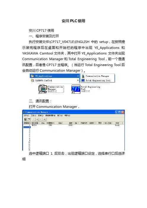
安川PLC使用安川CP717使用一、程序安装及打开执行安装文件\CP717_V0471E\ENGLISH中的setup,在按照提示装完程序后在桌面和开始栏的程序中出现YE_Applications和YASKAWA Camtool文件夹,其中打开YE_Applications 文件夹出现Communication Manager和Total Engineering Tool,前一个是通讯配置,后者是CP717主程序。
(当运行Total Engineering Tool后会自动运行Communication Manager)。
二、通讯配置:打开Communication Manager,选中逻辑端口1后双击,出现逻辑端口设定,选择串行口后选详细在弹出的窗口中进行通讯配置,其中单元号选择1,物理端口选择PC的物理通讯端口,通讯速度设为19200,数据位选8,奇校验,停止位1确定后完成通讯设置。
三、程序的清空及1、316H程序的清空在调试时,可能CPU模块中已经有调试的程序,需要首先删除CPU中的程序时删除的顺序是:A在通电状态下将CP-316H上的INT、TEST从OFF置ON,RUN从ON置OFF,保持一段时间后断电;B上电,RUN指示灯和RDY指示灯不停的闪动,保持一段时间后将RUN从OFF置ON,INT、TEST从ON置OFF断电C再送电CP-316中的程序已清空。
2、215RIO模块程序的清空将215RIO模块的SW旋钮的箭头分别拨为7、9位置上,按RESET按钮。
断开电源,保持一段时间后再送电,215RIO模块的程序被清空。
然后将其通讯地址再改为0、2。
四、上载下载1、打开T otal Engineering Tool,在ROOT上按右键新建组文件夹,名字任意如08000,在08000下建立指令文件夹,名字任意如PLC1,在PLC1上按右键新建PLC文件夹。
2、在弹出的对话框内对新PLC进行选型,如果是新建立的程序名字任意,如果是想读取电脑上已有的程序则名字要与现有名字一致,按第6步进行打开已有PLC文件的操作。
PLC操作规程范文PLC(可编程逻辑控制器)是工业控制领域常用的自动化设备,广泛应用于生产线、工厂和机械设备等各个行业。
对于PLC的操作规程,可以从以下几个方面进行详细说明。
一、安全操作规程1.维护设备安全:在操作PLC之前,必须确保设备的电源和主要部件已经正确连接并处于良好状态,防止发生电击、起火等意外事故。
2.使用合适的工具:操作PLC应该使用专门的工具,如编程软件、编程线缆,确保能够正确地读取和修改PLC的程序。
3.严禁擅自更改设备设置:未经授权人员不得擅自更改PLC的参数和程序,以免造成设备故障或生产事故。
4.定期检查和维护:定期对PLC进行检查和维护,保持其正常运行,并采取措施防止电源中断、操作误差等情况。
二、操作步骤规程1.启动PLC:按下PLC的启动按钮,等待设备的自检程序运行完毕,并确保设备处于正常工作状态。
2.编写或修改程序:使用合适的编程软件,编写或修改PLC的程序,确保所编写的程序逻辑正确、简洁,并与实际要求相匹配。
4.测试程序:对修改后的程序进行测试,确保PLC能够按照编写好的程序进行运行,并对程序中可能存在的问题进行排除和调整。
5.监控PLC状态:通过监控显示屏或相应的软件工具,实时监测PLC 的状态和运行情况,及时发现和解决可能存在的故障和问题。
6.停止PLC:在不需要使用PLC的情况下,及时停止设备的运行,关闭电源并清理现场。
三、应急处理规程1.故障排除:当PLC设备发生故障时,应迅速找出故障原因,并采取相应的措施进行修复。
同时,记录故障情况和处理结果,以备后续参考。
2.警报和通知:在出现严重故障或紧急情况时,应立即发出警报,并通知相关人员参与故障排除和应急处理。
3.备份程序:定期将PLC的程序进行备份,防止因为意外情况造成程序丢失,以确保设备能够迅速恢复运行。
四、培训和交流规程1.培训:针对PLC操作人员进行培训,使其熟练掌握PLC的基本操作和维护知识,并定期进行进一步的培训,以保持其专业技能。
YASKAWA程序操作指南第一章联机的条件及配置第一节通讯协议的配置1.首先安装CP-717软件,提供系统操作平台.2.CP-717软件安装后,在程序一栏中会有YE APPLICATION菜单,在YE APPLICATION菜单下有COMMUNICATION MANAGER和TOTAL ENGINEERING TOOL两个菜单。
3.点击COMMUNICATION MANAGER菜单,会出现COMMUNICATION PROCESS 的对话框,在对话框中设定通讯协议。
4.双击COMMUNICATION PROCESS 的对话框中的“1”,会出现LOGICAL PORT SETTING对话框,在PORT KIND选项中选SERIAL项,其它为默认,点击OK,通讯协议设置完成。
第二节子程序路径的建立及配置1.点击YE APPLICATION 菜单中的TOTAL ENGINEERING TOOL菜单,出现FILE MANAGER对话框。
2.选中FILE MANAGER对话框中的“ROOT”后,单击鼠标右健,会出现“NEW”“RENAME”“DELETE”三个选项,选中“NEW”后会出现“GROUP FOLDER”“ORDER FOLDER”,点击“ORDER FOLDER”。
3.点击“ORDER FOLDER”后,出现“MAKE NEW FOLDER”对话框,在空白处输入“ORDER NAME”如12号岸桥可输入QC12,然后回车。
4.选中QC12单击鼠标右健,会弹出“CREATE NEW FOLDER”“RENAME”“DELETE”三个选项,选中“CREATE NEW FOLDER”后会弹出“CONTROLLER FOLDER”单击“CONTROLLER FOLDER”。
5.单击“CONTROLLER FOLDER”,弹出“CONTROLLER CONFIGARATION”对话框,在“INFORMATION”目录下第一个“CONTROLLER”框中一般根据此控制器所处的网络号和站号编名如“N01S01”即一号网络一号站;“COMMENT”可不填写;第二个“CONTROLLER”为控制器的类型如“CP-317”“CP-316H”“CP-916A”“RIO2000”等等,一般“N01S01”的控制器的类型QC选“CP-317”,RTG选“CP-316H”。
YASKAWA Electric CorporationMP Series SIO(Extension) Driver1System Configuration (3)2Selection of External Device (6)3Example of Communication Setting (7)4Setup Items (9)5Cable Diagram (14)6Supported Device (16)7Device Code and Address Code (17)8Error Messages (18)IntroductionThis manual describes how to connect the Display and the External Device (target PLC).In this manual, the connection procedure will be described by following the below sections:1System ConfigurationThis section shows the types of ExternalDevices which can be connected and SIOtype.)"1 System Configuration" (page 3)2Selection of External DeviceSelect a model (series) of the ExternalDevice to be connected and connectionmethod.)"2 Selection of External Device" (page 6)3Example of Communication Settings This section shows setting examples forcommunicating between the Display andthe External Device.)"3 Example of Communication Setting"(page 7)4Setup ItemsThis section describes communicationsetup items on the Display.Set communication settings of the Displaywith GP-Pro Ex or in offline mode.)"4 Setup Items" (page 9)5Cable DiagramThis section shows cables and adaptersfor connecting the Display and theExternal Device.)"5 Cable Diagram" (page 14) Operation1System ConfigurationThe system configuration in the case when the External Device of YASKAWA Electric Corporation and the Display are connected is shown. Connection Configuration•1:1 ConnectionSeriesCPULink I/F SIO TypeSetting Example Cable Diagram MP2000MP2300MP2200MP2310MP2300SSerial port on 218IF-01RS232C "3.1 Setting Example 1" (page 7)" Cable Diagram 1" (page 14)Serial port on 218IF-02RS232C "3.1 Setting Example 1" (page 7)" Cable Diagram 1" (page 14)Serial port on 260IF-01RS232C "3.1 Setting Example 1" (page 7)" Cable Diagram 1" (page 14)Serial port on 261IF-01RS232C "3.1 Setting Example 1" (page 7)" Cable Diagram 1" (page 14)PORT on 217IF-01RS232C"3.1 Setting Example 1" (page 7)" Cable Diagram 1" (page 14)IPC COM PortWhen connecting IPC with an External Device, the COM port used depends on the series and SIO type. Please refer to the IPC manual for able portDIP Switch setting: RS-232CSeriesUsable PortRS-232CRS-422/485(4 wire)RS-422/485(2 wire)PS-2000BCOM1*1, COM2, COM3*1, COM4*1The RI/5V can be switched. Use the IPC’s switch to change if necessary.--PS-3450A, PS-3451A,PS3000-BA, PS3001-BD COM1, COM2*1*2COM2*1*2COM2*1*2PS-3650A (T41 model),PS-3651A (T41 model)COM1*1--PS-3650A (T42 model),PS-3651A (T42 model)COM1*1*2, COM2COM1*1*2COM1*1*2PS-3700A (Pentium®4-M)PS-3710A COM1*1, COM2*1, COM3*2, COM4*2Set up the SIO type with the DIP Switch. Please set up as follows according to SIO type to be 3*2COM3*2PS-3711A COM1*1, COM2*2COM2*2COM2*2PS4000*3*3When making communication between an External Device and COM port on the Expansion slot, only RS-232C is supported. However, ER (DTR/CTS) control cannot be executed because of the specification of COM port.For connection with External Device, use user-created cables and disable Pin Nos. 1, 4, 6 and 9. Please refer to the IPC manual for details of pin layout.COM1, COM2--PL3000COM1*1*2, COM2*1, COM3, COM4COM1*1*2COM1*1*2DIP SwitchSetting Description1OFF *1*1When using PS-3450A, PS-3451A, PS3000-BA and PS3001-BD, turn ON the set value.Reserved (always OFF)2OFF SIO type: RS-232C3OFF 4OFF Output mode of SD (TXD) data: Always output5OFF Terminal resistance (220Ω) insertion to SD (TXD): None 6OFF Terminal resistance (220Ω) insertion to RD (RXD): None 7OFF Short-circuit of SDA (TXA) and RDA (RXA): Not available 8OFF Short-circuit of SDB (TXB) and RDB (RXB): Not available 9OFF RS (RTS) Auto control mode: Disabled10OFFDIP Switch setting: RS-422/485 (4 wire)DIP Switch setting: RS-422/485 (2 wire)DIP SwitchSetting Description1OFF Reserved (always OFF)2ON SIO type: RS-422/4853ON 4OFF Output mode of SD (TXD) data: Always output5OFF Terminal resistance (220Ω) insertion to SD (TXD): None 6OFF Terminal resistance (220Ω) insertion to RD (RXD): None 7OFF Short-circuit of SDA (TXA) and RDA (RXA): Not available 8OFF Short-circuit of SDB (TXB) and RDB (RXB): Not available 9OFF RS (RTS) Auto control mode: Disabled10OFFDIP SwitchSetting Description1OFF Reserved (always OFF)2ON SIO type: RS-422/4853ON 4OFF Output mode of SD (TXD) data: Always output5OFF Terminal resistance (220Ω) insertion to SD (TXD): None 6OFF Terminal resistance (220Ω) insertion to RD (RXD): None 7ON Short-circuit of SDA (TXA) and RDA (RXA): Available 8ON Short-circuit of SDB (TXB) and RDB (RXB): Available 9ON RS (RTS) Auto control mode: Enabled10ON2Selection of External DeviceSelect the External Device to be connected to the Display.Setup Items Setup DescriptionNumber of Devices/PLCs Enter an integer from 1 to 4 to define the number of Devices/PLCs to connect to the display.ManufacturerSelect the manufacturer of the External Device to connect. Select "YASKAWA Electric Corporation".SeriesSelect the External Device model (series) and the connection method. Select "MP Series SIO (Extension)".In System configuration, make sure the External Device you are connecting is supported by "MP Series SIO (Extension)".)"1 System Configuration" (page 3)Port Select the Display port to connect to the External Device.Use System AreaCheck this option to synchronize the system data area of the Display and the device (memory) of the External Device. When synchronized, you can use the External Device’s ladder program to switch the display or display the window on the Display.Cf.GP-Pro EX Reference Manual "LS Area (Direct Access Method Area)"This feature can also be set in GP-Pro EX or in the Display's offline mode.Cf.GP-Pro EX Reference Manual "System Settings [Display Unit] - [System Area]Settings Guide"Cf.Maintenance/Troubleshooting Guide "Main Unit - System Area Settings"3Example of Communication SettingExamples of communication settings of the Display and the External Device, recommended by Pro-face, are shown.3.1Setting Example 1Settings of GP-Pro EXCommunication SettingsTo display the setup screen, from the [Project] menu, point to [System Settings] and select [Device/PLC].Device SettingTo display the [Individual Device Settings] dialog box, from [Device-Specific Settings] in the [Device/PLC]window, select the external device and click [Settings].Settings of External DeviceCommunication setting of communication module by ladder software (MPE720).Please refer to the manual of external device for more detail.Ladder Software Setting1Start ladder software, make an order folder and a PLC folder in a root folder.2Click the right button of the PLC which select logon in the displayed menu.3Double-click the [Definition folder]-[Module constitution] of the PLC folder, and display [Engineering Manager].4Select the rack classification and communication module, the pull-down menu in [Controller] of [Engineerring Manager].Set the number corresponding to the slot number that a communication module uses.Select the communication module, setting contents are displayed to [Module details] of [Enginnering Manager].5Double-click the number part at No. in [Module details].Double-click the slot number connecting the ethernet unit.Setup Items Setup DescriptionTransmission Protocol MEMOBUSMaster/Slave SlaveDevice Address Device address of the External DeviceSerial I/F RS-232CTransmission Mode RTUData Length8BitParity Bit evenStop Bit1StopBaud Rate19.2KSending DisableAutomatically Reception Disable6Double-click the "No.1", and set serial communication.Use serial communication setting to forward communication setting and the ladder program to the PLC.7Save setting content and finish [Engineering Manager].8DIP switch "INIT" of a communication module is ON and spend a power supply.9Forward communication setting to a communication module.10Logon the PLC at online and write in the data which transferred at flash memory.11Power supply of PLC is OFF and DIP switch of the INIT is OFF, after spend the power supply of PLC.4Setup ItemsSet communication settings of the Display with GP-Pro EX or in offline mode of the Display.The setting of each parameter must be identical to that of External Device.)"3 Example of Communication Setting" (page 7)4.1Setup Items in GP-Pro EXCommunication SettingsTo display the setup screen, from the [Project] menu, point to [System Settings] and select [Device/PLC].Setup Items Setup DescriptionSIO Type Display the SIO type to communicate with the External Device.Speed Select speed between External Device and Display.Data Length Select data length.Parity Select how to check parity.Stop Bit Select stop bit length.Flow Control Select the communication control method to prevent overflow of transmission and reception data.Timeout Use an integer from 1 to 127 to enter the time (s) for which Display waits for the response from External Device.Retry In case of no response from the External Device, use an integer from 0 to 255 to enter how many times the Display retransmits the command.continued to next pageDevice SettingTo display the [Individual Device Settings] dialog box, from [Device-Specific Settings] in the [Device/PLC]window, select the external device and click [Settings].Wait To SendUse an integer from 0 to 255 to enter standby time (ms) for the Display from receiving packets to transmitting next commands.RI/VCCYou can switch RI/VCC of the 9th pin when you select RS232C for SIO type.It is necessary to change RI/5V by changeover switch of IPC when connect with IPC. Please refer to the manual of the IPC for more detail.Device)"Setup Items Setup DescriptionStation No.Enter a station number of the External Device, using 1 to 63.Setup Items Setup Description4.2Setup Items in Offline ModeCommunication SettingsTo display the setting screen, touch [Device/PLC Settings] from [Peripheral Settings] in offline mode. Touch the External Device you want to set from the displayed list.Cf.Maintenance/Troubleshooting Guide "Offline Mode"•The number of the setup items to be displayed for 1 page in the offline mode depends on the Display in use. Please refer to the Reference manual for details.Device SettingTo display the setting screen, touch [Device/PLC Settings] from [Peripheral Settings]. Touch the External Device you want to set from the displayed list, and touch [Device].RetryIn case of no response from the External Device, use an integer from 0 to 255 to enter how many times the Display retransmits the command.Wait To Send (ms)Use an integer from 0 to 255 to enter standby time (ms) for the Display from receiving packets to transmitting next commands.Setup Items Setup DescriptionDevice/PLC Name Select the External Device for device setting. Device name is a title of External Device set with GP-Pro EX.(Initial value [PLC1])Station No.Enter a station number of the External Device, using 1 to 63.Setup Items Setup DescriptionOptionTo display the setting screen, touch [Device/PLC Settings] from [Peripheral Settings]. Touch the External Device you want to set from the displayed list, and touch [Option].Setup Items Setup DescriptionRI/VCCYou can switch RI/VCC of the 9th pin when you select RS232C for SIO type.It is necessary to change RI/5V by changeover switch of IPC when connect with IPC. Please refer to the manual of the IPC for more detail.5Cable DiagramThe cable diagram shown below may be different from the cable diagram recommended by YASKAWA Electric Corporation. Please be assured there is no operational problem in applying the cable diagram shown in this manual.•The FG pin of the External Device body must be D-class grounded. Please refer to the manual of the External Device for more details.•SG and FG are connected inside the Display. When connecting SG to the External Device, design the system not to form short-circuit loop.•Connect the isolation unit, when communication is not stabilized under the influence of a noise etc..Cable Diagram 1Display(Connection Port)Cable RemarksGP3000 (COM1)GP4000*1 (COM1)ST (COM1)LT3000 (COM1)IPC *2PC/AT*1All GP4000 models except GP-4100 Series and GP-4203T*2Only the COM port which can communicate by RS-232C can be used.)IPC COM Port (page 4)1A User-created cable The cable length must be 15m or less.GP-4105 (COM1)1B User-created cableThe cable length must be 15m or less.LT-4*01TM (COM1)1CRJ45 RS-232C Cable (5m) by Pro-facePFXZLMCBRJR211A)1B)1C)Legend Name Notes(1)RJ45 RS-232C Cable (5m) by Pro-face PFXZLMCBRJR216Supported DeviceRange of supported device address is shown in the table below. Please note that the actually supported range of the devices varies depending on the External Device to be used. Please check the actual range in the manual of your connecting equipment.This address can be specified as system data area.DeviceBit Address Word Address 32bitsNotesSystem registers SB000000 - SB08191F SW00000 - SW08191Input registers IB00000 - IBFFFFF IW0000 - IWFFFF *1*1As for Input and Output registers, device 0x9000-0xFFFF cannot be written.Output registers OB00000 - OBFFFFF OW0000 - OWFFFF *1Data registers MB000000 - MB65534FMW00000 - MW65534•Please refer to the precautions on manual notation for icons in the table.)"Manual Symbols and Terminology"7Device Code and Address CodeUse device code and address code when you select "Device Type & Address" for the address type in data displays.Device Device Name Device Code(HEX)Address CodeSystem registers SW/SB0080Word address Input registers IW/IB0001Word address Output registers OW/OB0081Word address Data registers MW/MB0000Word address8Error MessagesError messages are displayed on the screen of Display as follows: "No. : Device Name: Error Message (Error Occurrence Area)". Each description is shown below.Display Examples of Error Messages"RHAA035: PLC1: Error has been responded for device write command (Error Code: 2 [02H])"messages common to the driver.Error Code Peculiar to PLCThe error code peculiar to PLC is as follows.Error code Description0x90Transfer error.0x92Illegal parameter.0x96Register No. over.0x9C File is modified.0x9D Data access error.Error Messages Specific to the External DeviceMessage ID Error Message Description RHxx128"(Node Name):PLC is busy now(Error Code: [Hex])"PLC is "Busy"RHxx129"(Node Name):Option module is not mounted(Error Code: [Hex])"Option module not mount. RHxx130"(Node Name):Module is not ready(Error Code: [Hex])"Module is not ready RHxx131"(Node Name):CPU is stopped(Error Code: [Hex])"CPU is stoppedRHxx132"(Node Name): Write protected(Error Code: [Hex])"Write protected。
模块式PLC实训指导书主编:郑渊崔忠毅2011年10月目录项目一安川PLC控制系统识图 (3)项目二安川PLC硬件组态及测试 (12)项目三控制起升电机正反转 (20)项目一安川PLC控制系统识图一、项目导入日本安川电机公司(YASKAWA)成立于1915年,该公司制造的PLC和变频器产品在我国港口大型装卸机械中应用较为广泛,如图1、2所示。
图1 安川模块式PLC 图2 安川G7变频器图3所示为轮胎吊实训台,该实训台采用安川PLC和变频器,其控制系统与港口实际PLC控制系统基本一致,本项目的任务是读懂该实训台PLC控制系统电气图纸,从而对模块式PLC控制系统有一个整体上的把握。
图3 轮胎吊实训台二、项目分析模块式PLC控制系统由于一般应用于较为复杂的电气控制中,所以其电气图纸相对于整体式PLC控制系统或继电器控制系统要复杂一些,但是也可以分为主电路和控制电路两部分。
对于采用模块式PLC控制系统的港口大型装卸机械来讲,可以分成以下几个部分:(一)主电路安川PLC安川变频器1、主驱动电路,例如驱动大机各机构动作的电路,现在一般采用变频调速。
2、辅助机构驱动电路,例如大机各机构风机电路、制动器电路等,一般采用工频电源,不需变频调速。
(二)控制电路1、PLC外部控制电路,该部分电路既不是PLC输入回路,也不是PLC输出回路,而主要是输入输出的中继电路或者安全电路。
2、PLC模块配置电路,该部分电路表明PLC控制系统采用何种CPU模块、电源模块、输入输出模块、特殊功能模块、通讯模块等,同时说明了PLC控制系统的网络通讯结构和输入输出模块的地址分配等重要信息。
3、PLC输入回路,一般每页图纸绘制16个输入点,并标明每个输入点所对应输入设备的功能。
4、PLC输出回路,一般每页图纸绘制16个输出点,并标明每个输出点所对应输出设备的功能。
二、项目实施(一)供电线路1、主电路供电如附录P1所示,轮胎吊实训台采用主变压器输出的380V工频交流电源供电,经空气开关QF1给主电路供电。