阿里斯顿慧心系列电热水器说明书
- 格式:pdf
- 大小:14.92 MB
- 文档页数:10
ariston热水器控制面板说明书第一章:安全说明1.在安装和使用本产品之前,请仔细阅读本说明书并按照指示操作。
2.在进行任何维修和清洁操作之前,请先关闭电源。
3.安装和维修应由专业技术人员进行。
4.避免触摸热水器控制面板,以免烫伤。
5.不要在淋浴时打开热水器门,以防止热水喷溅。
6.使用本产品时,请确保周围通风良好。
7.如果发现热水器电源线损坏,请及时更换以防危险。
第二章:控制面板介绍控制面板主要包括开关按钮、温度调节器和显示屏。
1.开关按钮:用于启动和关闭热水器。
按下按钮开启热水器,再次按下将关闭热水器。
2.温度调节器:用于调节热水温度。
根据需要,可以选择合适的温度。
3.显示屏:显示热水器的工作状态和温度。
可以通过显示屏了解热水器的运行情况。
第三章:使用指南1.打开热水器:按下开关按钮,显示屏上会显示“ON”,热水器将开始工作。
2.关闭热水器:再次按下开关按钮,显示屏上会显示“OFF”,热水器将停止工作。
3.调节温度:通过旋转温度调节器,可以选择希望的热水温度。
请注意,温度调节范围通常为30℃~60℃,请根据实际需要进行调整。
4.显示屏信息:显示屏上会显示当前热水温度、热水器工作状态等信息。
根据需要,随时查看热水器的运行情况。
第四章:故障处理第五章:维护保养1.清洁热水器:定期清洁热水器,以确保其正常运行。
清洁过程中,请务必关闭热水器的电源。
2.更换热水器过滤器:根据使用情况,定期更换热水器过滤器。
更换过滤器前,必须先关闭热水器的电源,并按照说明书的指示进行更换。
第六章:注意事项1.孩童禁止接近:请保持孩童远离热水器,以防止意外发生。
2.禁止私自拆卸:非专业技术人员禁止私自拆卸热水器或控制面板。
3.避免封闭环境:热水器应放置在通风良好的地方,远离易燃物品和高温物体。
4.防止触摸:热水器在工作过程中会产生高温,切勿触摸热水器外壳和控制面板,以免烫伤。
总结:。
4.3 向浴缸内注水4.3.1使用前准备¥ 关闭浴缸的放水栓;¥ 如果有浴缸盖请盖上。
(注水时请打开)4.3.2 通过面板操作器注水时请按照以下的方法进行A. 初次使用时,按下面板操作器的电源开关,面板显示器闪烁显示标准模式的水温"42℃",3秒钟后显示实际出水温度。
标准模式下的水温(例42℃)标准模式下的水温(例42℃)优先显示亮¥ 热水器的设定温度范围为35℃-70℃,在温度范围35℃-48℃区间内,按下温度设定按键以1℃为单位上升或下降,而 且设定完温度时,会闪烁显示3秒设定温度,随后显示实际水温;在温度范围50℃-70℃区间,按下温度设定按键是以 5℃为单位上升或下降,且设定温度完成后会闪烁10秒显示设定温度,随后显示实际水温。
¥ 为了使机器在进水温度较低的情况下,也能达到更好的恒温使用性能,在部分额定热负荷较小的机型上特设水量调节 旋钮。
当出现出水温度低于设定温度时,请将水量调节旋钮适当关小, 使得到最佳的恒温调节范围.”¥ 当超出机器使用范围而无法达到设定温度,不属于产品质量问题,可通过调节进水量达到设定温度.4.2 水温调节¥ (热水器同时连接面板操作器和浴室有线遥控器时)正在使用热水时¥ 无法从35~48℃的温度设定改变为高温(50℃,55℃,60℃,65℃,70℃)。
¥ 设定为高温(50℃,55℃,60℃,65℃,70℃)时,无法升高温度。
Hi7机型:Ei7+/Ei6+机型:¥ Hi7系列通过按auto 按键,使LCD 上的"浴缸模式"闪烁,同时显示屏会闪烁显示水量设定值,此时可通过上下键设定水 量。
¥ 对Ei7+和Ei6+系列按下水量设定开关,LCD 显示屏会闪烁显示水量设定值时,按触上下按键进行水量设定。
¥ 设定水量范围为10~990升(每10升为1单位),用户可根据自己需求任意设定。
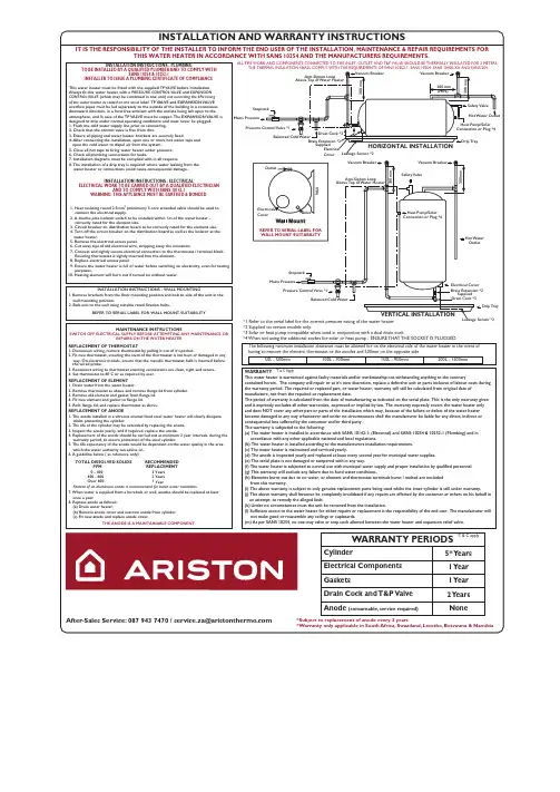
YearYears Years INSTALLATION INSTRUCTIONS - ELECTRICALELECTRICAL WORK TO BE CARRIED OUT BY A QUALIFIED ELECTRICIANAND TO COMPLY WITH SANS 10142-1WARNING: THIS APPLIANCE MUST BE EARTHED & BONDEDINSTALLATION INSTRUCTIONS - PLUMBINGTO BE INSTALLED BY A QUALIFIED PLUMBER AND TO COMPLY WITHSANS 10254 & 10252-1INSTALLER TO ISSUE A PLUMBING CERTIFICATE OF COMPLIANCETHIS WATER HEATER IN ACCORDANCE WITH SANS 10254 AND THE MANUFACTURERS REQUIREMENTS.IT IS THE RESPONSIBILITY OF THE INSTALLER TO INFORM THE END USER OF THE INSTALLATION, MAINTENANCE & REPAIR REQUIREMENTS FORINSTALLATION AND WARRANTY INSTRUCTIONSREFER TO SERIAL LABEL FOR OutletInletW a l lElectrical CoverBalanced Cold WaterPressure Control Valve *1Mains PressureStopcockHeat Pump/Solar Connection or Plug *4Heat Pump/SolarConnection or Plug *4Drain Cock *3Brass Extension *2Supplied Electrical Cover Drip TrayDrip TrayHot Water OutletHot Water OutletSafety ValveSafety ValveAnti-Siphon LoopAbove Top of Water HeaterVacuum BreakerVacuum BreakerVacuum Breaker Anti-Siphon LoopBalanced Cold WaterMains PressurePressure Control Valve *1Vacuum BreakerStopcock*Subject to replacement of anode every 2 years*Warranty only applicable in South Africa, Swaziland, Lesotho, Botswana & NamibiaALL PIPE WORK AND COMPONENTS CONNECTED TO THE INLET, OUTLET AND T&P VALVE SHOULD BE THERMALLY INSULATED FOR 2 METERS.THE THERMAL INSULATION SHALL COMPLY WITH THE REQUIREMENTS OF SANS 10252-1, SANS 10254, SANS 10400-XA AND SANS 204.1. Remove brackets from the floor mounting position and bolt to side of the unit in the wall mounting position.2. Bolt unit to the wall using suitable rated fixation bolts.REFER TO SERIAL LABEL FOR WALL MOUNT SUITABILITYINSTALLATION INSTRUCTIONS - WALL MOUNTING*1 Refer to the serial label for the correct pressure rating of the water heater.*2 Supplied on certain models only.*3 Solar or heat pump compatible when used in conjunction with a dual drain cock.*4 When not using the additional socket for solar or heat pump - ENSURE THAT THE SOCKET IS PLUGGED.300 m m300 m mWALL MOUNT SUITABILITYDrain Cock *3ElectricalCover200 mm 300 m m(MIN)300 m mHORIZONTAL INSTALLATION VERTICAL INSTALLATIONBrass Extension *2SuppliedThe following minimum installation clearance must be allowed for on the electrical side of the water heater in the event of having to remove the element, thermostat or the anodes and 500mm on the opposite side.WARRANTY This water heater is warrantied against faulty materials and/or workmanship not withstanding anything to the contrarycontained herein. The company will repair or at it’s own discretion, replace a defective unit or parts inclusive of labour costs during the warranty period. The repaired or replaced part, or water heater, warranty will still be calculated from original date of manufacture, not from the repaired or replacement date.The period of warranty is calculated from the date of manufacturing as indicated on the serial plate. This is the only warranty given and it expressly excludes all other warranties, expressed or implied by law. The warranty expressly covers the water heater only and does NOT cover any other part or parts of the installation which may, because of the failure or defect of the water heater become damaged in any way whatsoever and under no circumstances shall the manufacturer be liable for any direct, indirect or consequential loss suffered by the consumer and/or third party.The warranty is subjected to the following:(a) The water heater is installed in accordance with SANS 10142-1: (Electrical) and SANS 10254 & 10252-1 (Plumbing) and in accordance with any other applicable national and local regulations.(b) The water heater is installed according to the manufacturers installation requirements.(c) The water heater is maintained and serviced yearly.(d) The anode is inspected yearly and replaced at least every second year for municipal water supplies.(e) The serial plate is not damaged or tampered with in any way.(f) The water heater is subjected to normal use with municipal water supply and proper installation by qualified personnel.(g) This warranty will exclude any failure due to hard water conditions.(h) Elements burnt out due to no water, or element and thermostat terminals burnt / melted are excluded from this warranty.(i) The above warranty is subject to only genuine replacement parts being used whilst the inner cylinder is still under warranty.(j) The above warranty shall however be completely invalidated if any repairs are effected by the customer or others on his behalf in an attempt, to remedy the alleged fault.(k) Under no circumstances must the unit be removed from the installation.(l) Sufficient access to the water heater for either repairs or replacement is the responsibility of the end user. The manufacturer will not make good or reassemble any ceilings or cupboards.(m) As per SANS 10254, no one-way valve or stop cock allowed between the water heater and expansion relief valve.*T & C Apply1. The anode installed in a vitreous enamel lined steel water heater will slowly dissipate whilst protecting the cylinder.2. The life of the cylinder may be extended by replacing the anode.3. Inspect the anode yearly, and if required, replace the anode.4. Replacement of the anode should be carried out at minimum 2 year intervals, during the warranty period, to ensure protection of the steel cylinder.5. The life expectancy of the anode would be dependent on the water quality in the area, which the water authority can advise on.6. A guideline below ( as reference only):7. When water is supplied from a borehole or well, anodes should be replaced at least once a year.8. Replace anode as follows: (a) Drain water heater.(b) Remove anode cover and unscrew anode from cylinder. (c) Fit new anode and replace anode cover.MAINTENANCE INSTRUCTIONSSWITCH OFF ELECTRICAL SUPPLY BEFORE ATTEMPTING ANY MAINTENANCE ORREPAIRS ON THE WATER HEATER REPLACEMENT OF THERMOSTAT1. Disconnect wiring, remove thermostat by pulling it out of it’s pocket.2. Fit new thermostat, ensuring the stem of the thermostat is not bent or damaged in any way. On electronic models, ensure that the metallic thermostat bulb is inserted before3. Reconnect wiring to thermostat ensuring connections are clean, tight and secure.4. Set thermostat to 60˚C or as required by user.REPLACEMENT OF ELEMENT 1. Drain water from the water heater.2. Remove thermostat as above and remove flange lid from cylinder.3. Remove old element and gasket from flange lid.4. Fit new element and gasket to flange lid.5. Refit flange lid, and replace thermostat as above.REPLACEMENT OF ANODETOTAL DISSOLVED SOLIDS RECOMMENDEDPPM REPLACEMENT0 - 400 3 400 - 600 2 Over 600 1Fitment of an aluminium anode is recommended for harsh water conditions.THE ANODE IS A MAINTAINABLE COMPONENTThis water heater must be fitted with the supplied TP VALVE before installation.Always fit this water heater with a PRESSURE CONTROL VALVE and EXPANSION CONTROL VALVE (which may be combined in one unit) not exceeding the kPa rating of the water heater as stated on the serial label. TP VALVE and EXPANSION VALVE overflow pipes must be led separately to the outside of the building in a continuous downward direction, in a frost free ambient with the outlets being left open to the atmosphere, and in case of the TP VALVE must be copper. The EXPANSION VALVE is designed to drip under normal operating conditions and must never be plugged.1. Flush the cold water supply line prior to connecting.2. Check that the control valve is free from dirt.3. Ensure all piping and water heater brackets are securely fixed.4. After connecting the installation, open one or more hot water taps and open the cold water to dispel air from the system.5. Close all hot taps to bring water heater under pressure.6. Check all plumbing connections for leaks.7. Installation diagrams must be complied with in all respects.8. The installation of a drip tray is required where water leaking from the water heater or connections could cause consequential damage.WARRANTY PERIODS*T & C apply5* Y ears 1 Y ear 1 Y ear 2 Y ears NoneCylinderElectrical Components GasketsDrain Cock and T&P Valve Anode (consumable, service required)Above Top of Water Heaterthe wired probe.1. Heat resisting round2.5mm (minimum) 3 core stranded cable should be used to connect the electrical supply.2. A double pole isolator switch to be installed within 1m of the water heater - correctly rated for the element size.3. Circuit breaker on distribution board to be correctly rated for the element size.4. Turn off the circuit breaker on the distribution board as well as the isolator at the water heater.5. Remove the electrical access panel.6. Cut away tips of old electrical wire, stripping away the insulation.7. Connect and tightly secure electrical connection to the thermostat / terminal block. Ensuring thermostat is tightly inserted into the element. 8. Replace electrical access panel.9. Ensure the water heater is full of water before switching on electricity, even for testing purposes.10. Heating element will burn out if turned on without water.2After-Sales Service: 087 943 7470 / service.za@200L - 1500mm150L - 950mm100L - 700mm50L - 500mmLeakage Sensor *2Leakage Sensor *2。
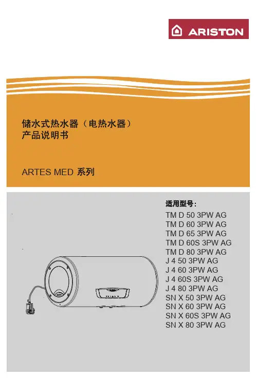
目录功能与特点 (1)各部分零件名称 (2)使用前准备 (5)使用方法 (6)使用注意事项 (10)防冻注意事项 (12)安装 (13)试运行 (19)日常检查及保养 (19)故障、异常的判断及处理方法 (20)规格表 (21)配线图 (22)一.功能与特点一. 功能与特点采用静电喷涂处理,可搭配各款现代厨房设计,结构紧凑,机身小巧,大大节省了安装空间。
操作简单双低压启动缓点火设计操作面板显示水温调节方便可拆式过滤装置瞬间停电或降压的安全保护设计1外型美观12345678多重安全保护装置,使用更放心10● 自动熄火保护装置, 使用过程中发生意外熄火时,本机会自动关闭气源,防止燃气外泄,安全可靠。
● 超时使用安全装置,连续使用30分钟后,热水器自动停机,若要继续使用,只需关上热水阀,数秒后再开启即 可重新点火。
● 强制鼓风燃烧方式设计,采用高效能风机将烟气全部排放室外,确保使用安全。
●另配有过热保护装置,水过压泄压装置,风机停转安全保护装置,防止空烧安全保护装置,排烟管堵塞保护装 置,防冻保护装置(仅限防冻机型)等,确保热水器在正常状态下工作。
●Pa1/Pa2机型使用auto功能模式时有48°安全锁保护。
●Pb1机型提供使用48°安全锁保护的选项,使用此选项可确保热水器在出水温度不高于48°的火力分段下燃烧, 确保您的安全使用。
当供电网络电压瞬间跌落或停电时,仍能保持热水器正常工作或安全停机。
自动变升功能(Pa1/Pa2)9特设有自动变升功能,在自动变升模式下使用时,系统会根据用户的实际需求与季节不同,自动变升调节火力段进行燃烧,以最优化的状态工作,节能省气。
省电设计11本机处于待机并显示屏点亮的状态下,如2分钟内未做任何操作,则显示器背光源会关闭,如需查看只需按触电源开关按键则背光源点亮。
P1/Pa1/Pb1面板操作器可以自由调控升位大小,燃烧指示灯显示工作状态;Pa2 LED数码显示屏显示出水温度、升位大小及工作状态,一目了然 。
设备操作说明书
第 1 页 共 2页
设备名称 电热水器 设备功能 供应热水 文件编号 设备型号
DSZF-50
厂 商
华时雅
版 本
B0
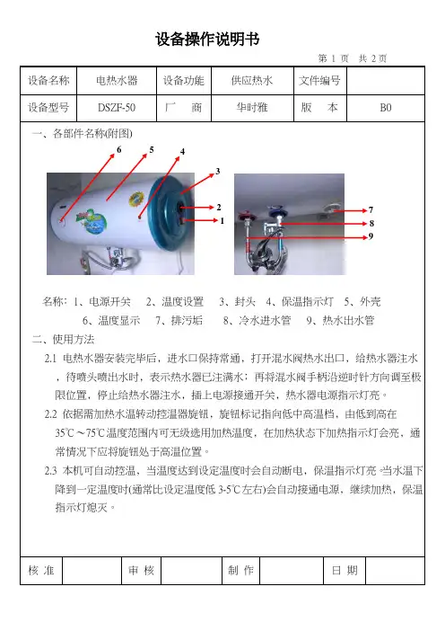
一﹑各部件名称(附图)
名称﹕1﹑电源开关 2﹑温度设置 3﹑封头 4﹑保温指示灯 5﹑外壳 6﹑温度显示 7﹑排污垢 8﹑冷水进水管 9﹑热水出水管 二﹑使用方法
2.1 电热水器安装完毕后﹐进水口保持常通﹐打开混水阀热水出口﹐给热水器注水﹐待喷头喷出水时﹐表示热水器已注满水﹔再将混水阀手柄沿逆时针方向调至极限位置﹐停止给热水器注水﹐插上电源接通开关﹐热水器电源指示灯亮。
2.2 依据需加热水温转动控温器旋钮﹐旋钮标记指向低中高温档﹐由低到高在35℃~75℃温度范围内可无级选用加热温度﹐在加热状态下加热指示灯会亮﹐通常情况下应将旋钮处于高温位置。
2.3 本机可自动控温﹐当温度达到设定温度时会自动断电﹐保温指示灯亮。
当水温下降到一定温度时(通常比设定温度低3-5℃左右)会自动接通电源﹐继续加热﹐保温指示灯熄灭。
核 准 审 核 制 作 日 期
5
2
1
3
4
6
7 8 9
设备操作说明书
第 2 页共2 页。
设备操作说明书
第 1 页 共 2页
设备名称 电热水器 设备功能 供应热水 文件编号 设备型号
DSZF-50
厂 商
华时雅
版 本
B0
一﹑各部件名称(附图)
名称﹕1﹑电源开关 2﹑温度设置 3﹑封头 4﹑保温指示灯 5﹑外壳 6﹑温度显示 7﹑排污垢 8﹑冷水进水管 9﹑热水出水管 二﹑使用方法
2.1 电热水器安装完毕后﹐进水口保持常通﹐打开混水阀热水出口﹐给热水器注水﹐待喷头喷出水时﹐表示热水器已注满水﹔再将混水阀手柄沿逆时针方向调至极限位置﹐停止给热水器注水﹐插上电源接通开关﹐热水器电源指示灯亮。
2.2 依据需加热水温转动控温器旋钮﹐旋钮标记指向低中高温档﹐由低到高在35℃~75℃温度范围内可无级选用加热温度﹐在加热状态下加热指示灯会亮﹐通常情况下应将旋钮处于高温位置。
2.3 本机可自动控温﹐当温度达到设定温度时会自动断电﹐保温指示灯亮。
当水温下降到一定温度时(通常比设定温度低3-5℃左右)会自动接通电源﹐继续加热﹐保温指示灯熄灭。
核 准 审 核 制 作 日 期
5
2
1
3
4
6
7 8 9
设备操作说明书
第 2 页共2 页。
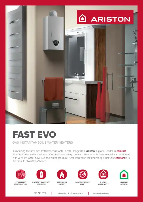
**************************************GAS INSTANTANEOUS WATER HEATERSFAST EVOIntroducing the new Gas Instantaneous Water heater range from Ariston , a global leader in comfort. FAST EVO c ombines easiness of installation and high comfort. Thanks to its technology it can work even with very low water flow rate and water pressure. Rest assured in the knowledge that your comfort is in the most trustworthy of hands.ITALIAN DESIGNCONSTANT TEMPERATURE BATTERY POWEREDIGNITION LOW PRESSURESTART 2 YEAR WARRANTY MAXIMUM SAFETYFor further information visit our website Ariston Service 010 745 9911DESCRIPTION16 LITRESDimension in mm (H x L x W)580 x 370 x 250Weight (net)11,1 [kg]Electricity supply 2x 1,5 V LR 20Ignition technology Direct mechanic Nominal heat input (min - max)10,5 - 27 [kW]Nominal heat output (min - max)9 - 23 [kW]Water pressure (min - max)0,1 - 10 [bar]Gas Consumption (max)2,45 [kg/h]FAST EVOFEATURES AND BENEFITS/ Continuous flame modulation via the NTC sensor located at the heater exchanger outlet (maximum temperature stability)/ Minimum operating pressure of 0.1 bar/ Also operates with a minimum water flow rate of 2 l/min / Up-to-date technology for complete safety / Electronic flame detectionOVERALL DIMENSIONSØab c def ghijk lm16L132580701172643704858,8131,52302502311,222,5TECHNICAL INFORMATIONB. Hot water outlet 1/2”C. Gas Inlet 1/2”D. Cold water inlet 1/2”FLUE DIMENSIONS (mm)Ø1a 1b 1c 1d Fast Evo 16L1325001000806001a1c1b1dIndoorWhen unit is installed indoors, the room must be ventilated as per SANS 10087-1OutdoorIf the unit is installed outside, it must be covered with aweather boxUNIT MUST BE INSTALLED WITH A FLUE。

ARISTON GAS WATER HEATER INFORMATION SHEETCORRECT INSTALLATIONThe appliance may only be installed by a gas installer registered with the SAQCC, and installed in accordance with the requirements of SANS 10087-1 for the use with LPG, SANS 827 for the use with NG. All gas appliances must be verified to ensure LP Gas appliances conform LP Gas appliances conform with the SANS 1539specification.LOCATION OF INSTALLATIONAriston gas instantaneous water heaters gives you the flexibility to install on virtually any wall inside or outside your home.MINIMUM CLEARANCESIn order to allow easy access to appliances formaintenance operations. The appliance must be installed in accordance with the clearances stated below.INSTALLATION POSITIONRefer to the requirements of SANS 10087-1, SANS 827, local firedepartment and/or local by-laws for the correct placement of your gas equipment and appliances.2 YEAR WARRANTY ITALIAN DESIGNBATTERYPOWERED IGNITION EXTRA SAFETY SIMPLE INSTALLATION EASY TEMPERATURECONTROL UNIT MUST BE INSTALLED WITH A FLUEFLUE DIMENSIONS (mm)Ø1a1b1c1dFast R 11L 112500100080600Fast R 14L132Fast Evo 16L1321a1c1bIndoorWhen unit is installed indoors, the room must be ventilated as per SANS 10087-11dOutdoorIf the unit is installed outside, it must be covered with aweather box**************************************WHAT SIZE DO I NEEDWith gas instantaneous water heaters it doesn’t really matter how many people there are in your house. What matters more is how many ofthem are going to use hot water at the same time. GIWH provide endless hot water on demand, but is limited to the flow rate of the unit. A unit with 16l/min would only be able to supply hot water at a flowrate of 16l/min, which would be sufficient for most showers. For any additional shower you open, the 16l/min would have to be shared among the shower, which will result in a reduced flow and user experience at each shower. Therefore it is extremely important to understand the peak flow required at any given time. We recommend using Low Flow fittings in showers and on taps to get the best results from your water heater.HOW DOES A GAS INSTANTANEOUS WATER HEATER WORK?A Gas Instantaneous Water Heater does not store any water, it heats up cold water as it flows through the unit. Once a tap is opened and the water starts flowing, the unit picks up that there is flow through a sensor (5). As this happens the gas valve (4) opens and the Ignition electrode ignites the gas (a ticking will be heard as a spark is created by the electrode). The cold water then runs through the Heat Exchanger (1) and gets heated to the selected setting. The unit has many sensors for increased safety. If the unit gets too hot, it will be shut off by the sensors (7) or (8). If the flame is extinguished, the electrode (6) will shut off the gas supply.TECHNICAL INFORMATIONFAST RFAST EVO1. Heat exchanger2. Burner3. Hot water temperaturesensor 4. Gas valve5. Water flow switch6. Ignition and detectionelectrode7. Overheat thermostat 8. Fume sensor9. Cold water inlet filter B. Hot water outlet 1/2”C. Gas Inlet 1/2”D. Cold water inlet 1/2”9678154321. Heat exchanger 2. Burner 3. -4. Gas valve 5. Water valve6. Ignition and detectionelectrode7. Overheat thermostat 8. Fume sensor9. Cold water inlet filter B. Hot water outlet 1/2”C. Gas Inlet 1/2”D. Cold water inlet 1/2”96781542FAST ROVERALL DIMENSIONSØa b cde f g h i j k l m 11L 11255044.5109.3215.832544.3111.4210223.725.728111.424.514L1325807013223837028.893.9210.8225.511.42592.820.1A. Hot water outlet G1/2”B. Gas inlet G1/2”C.Cold water inlet G1/2”FAST EVOOVERALL DIMENSIONSØa b c d e f g h i j k l m 16L132580701172643704858.8131.52302502311.222.5B. Hot water outlet 1/2”C. Gas Inlet 1/2”D.Cold water inlet 1/2”。
用户手册尊敬的顾客:非常感谢您选购我们阿里斯顿的燃气采暖热水炉(以下简称热水炉)。
我们承诺已向您提供了一个技术合格的产品。
本手册用于告知您关于正确安装、使用和保养的方法和各种建议。
请您妥善保存本手册,以备以后查阅。
我们的地区技术服务中心将随时为您提供服务。
AUTO自动功能AUTO自动功能用来优化热水炉性能,同时保持最佳散热温度和最大用户舒适度。
在保证室内理想的温度环境下,同时节约能源。
其原理是根据室内环境温度自动调整热水炉出水口的温度。
保 修热水炉第一次点火应由制造商指定的工作人员实施。
包修期根据发票购机日期开始计算,具体包修政策请参考保修卡。
在核实了热水炉已正确安装并进行第一次点火之后,您的热水炉才能正式使用。
至于对燃气回路、水路以及电气回路的维修,请与当地指定的技术服务中心联系。
在中国市场销售的热水炉的数据和操作以中文技术说明书为准产品标准本产品执行以下中国产品标准:GB25034 燃气采暖热水炉GB20665 家用燃气快速热水器和燃气采暖热水炉能效限定值及能效等级产品寿命依据G B17905相关规定,采暖热水炉从出售之日起,使用天然气的采暖热水炉的使用年限为8年,为了保证您的舒适安全使用,请严格遵守。
处理和回收热水炉我们的热水炉设计制造成大部分组件为可回收材料热水炉和它的附件必须尽可能地充分处理、材料分类。
热水炉运输的包装必须有安装工或经销商处理。
注意!!热水炉和附件的回收和处理必须按照法规要求执行。
用户手册安全守则关键符号不遵守本警告会有损坏的风险,在某些情况对财产、动植物甚至很严重。
用户手册应当把热水炉连接到适合于其性能和功率的生活热水系统和供暖系统。
严禁使用与规定不同的场所。
制造商不对出自不恰当、错误和不合理使用引起的损坏负责。
应当遵照现行的行业及相关标准、制造商所提供的要求而实施安装、保养及其它任何操作。
制造商不对由于错误安装引起的人员、动物以及财产的损害负责。
任何对排烟管道或进气管道的维修和操作,必须通过断开外部开关而切断电源,同时关闭气阀。
5
23
7
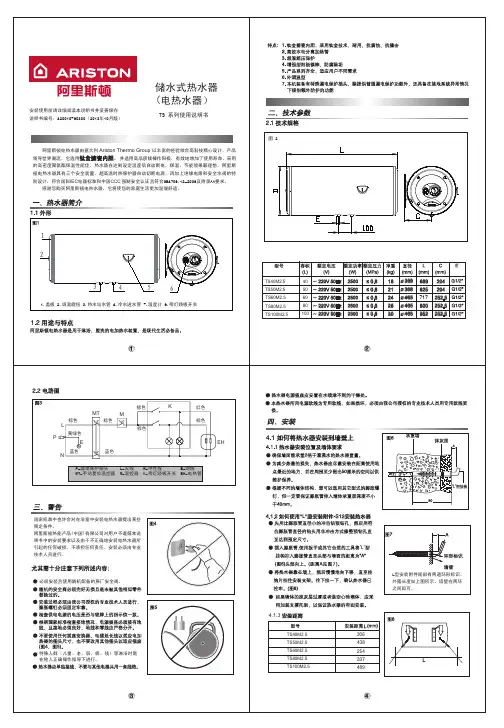
阿里斯顿舒心系列电热水器是供家庭、企事业单位和服务业等用于淋浴、盥洗的电加热水装置,是现代生活必备品。
钛金搪瓷内胆,采用超厚钢板及钛金搪瓷粉,耐用、抗腐蚀超温超压保护特大阳极镁棒,防腐除垢产品系列齐全,适应用户不同需求12. 热水出水管 3. 冷水进水管 6.调温旋钮 7.温度计
国家标准中也许会对在浴室中安装电热水器提出某些限定条件。
默洛尼卫生洁具(中国)有限公司对用户不遵循本说明书的安装要求以及由于不正确的安装电热水器所引起的任何破损,不承担任何责任。
安装必须由我公司授权或认可的专尤其需十分注意下列所述内容:
必须按照相应章节中的要求联接导线。
随机的安全阀必须完好无损且是未被其他相似零件替换过的。
安装过程必须由我公司授权或认可的专业技术人员进行,膨胀螺钉必须固定牢靠。
检查供电电源的电压是否与铭牌上的指示值 一致,检查电表、电源插座和电线直径 是否符合热水器的额定电流。
根据国家标准检查接地情况,电源插座必须接有地线,且接地必须良好,地线和零线 应严格分开。
严禁在无可靠接地的情况下使用电热水器。
不要使用任何插座变换器、电缆延长线以适应电加热器的插头尺寸,也不要改用其他请不要使用接线板。
图7
图8
F
A
D
B
C
横式。
电热水器使用说明电热水器是一种方便快捷的家用电器,可以将自来水加热为热水,提供给家庭洗浴、洗涤等用途。
热水器的使用说明书对于用户来说非常重要,可以帮助用户正确使用和维护热水器,确保其安全有效地运行。
下面是电热水器使用说明的一般内容。
1.产品概述首先,使用说明需要对电热水器的产品概述进行介绍。
包括产品的型号、主要功能、技术参数等。
用户可以通过阅读产品概述了解到自己购买的热水器的基本情况,如加热功率、容量等,以及其适用范围和性能特点。
2.安全警告然后,使用说明书需要列出热水器的安全警告事项,以帮助用户避免不正确的使用和操作造成的人身伤害和财产损失。
这些安全警告事项通常包括:-不得私自拆卸或修理热水器;-不得将热水器放置在易燃、易爆物品附近;-不得将电热水器放置在潮湿的环境中;-注意正确接地,避免漏电;-充分通风,避免因缺氧而发生事故等。
3.安装和操作在使用说明书的安装和操作部分,需要详细介绍热水器的安装、开启和关闭等操作步骤,以及相关注意事项。
这些包括:-热水器的安装位置选择,如要求选择安装在垂直墙面上,不得倾斜安装等;-热水器的水电管接口,如介绍进水口、出水口、电源插座等,并提供相应的接口参数要求;-热水器的开机操作,详细说明按下电源开关后热水器的状态变化和指示灯的闪烁情况;-热水器的调节操作,介绍如何调节热水器的温度、定时开关等功能并提供相应操作步骤。
4.维护和保养使用说明书还需要介绍热水器的维护和保养方法,以延长热水器的使用寿命。
这些方法包括:-定期清洗热水器内部,以避免结垢和杂质对加热元件的影响;-定期检查电线和插头的接触是否良好,以避免线路老化和短路故障;-定期检查热水器的安全阀和排放管是否畅通,以保证压力和温度的正常释放;-定期更换热水器内部的滤网和过滤器,以避免杂质积累和阻塞;5.故障排除在使用说明书中,还需要提供一些常见故障和解决方法,以帮助用户在热水器出现故障时快速定位和处理。
这些包括:-热水器无法加热的可能原因和解决方法,如检查电源是否正常供电;-热水器出水温度异常的可能原因和解决方法,如检查温度调节器设定值是否正确;-热水器漏水的可能原因和处理方法,如检查密封圈是否老化或松动等。
arizxin热水器说明书
XX热水器使用说明:
1、将能正常使用的电热水器电源插头对准插座插好。
2、将电热水器下面两个阀门同时拧开,一个是流出热水的阀门,另一个是注进冷水的阀门。
3、找到电热水器上的温度调节器,根据自己的需求设置好温度,当水温设置好后,温控器会自动接通。
4、调节使用温度,使用热水时,可以通过旋转水龙头来调节水的温度。
一般来说往红色(或H字样)方向旋转是热水,往蓝色(C 字样)方向旋转是冷水。
5、若是不经常使用的话,可以选用速热型的电热水器,速热式电热水器打加热时间只需要15分钟,加热速度快,等待时间短。