大学生方程式赛车悬架资料
- 格式:docx
- 大小:288.93 KB
- 文档页数:10


大学生方程式赛车悬架系统设计大学生方程式赛车悬架系统设计中国大学生方程式汽车大赛,在XX年开始举办,至XX 年已举办三届,大赛目的是为了提高大学生汽车设计与团队协作等能力,而华南农业大学XX年才组队设计赛车,现在还没有派队参加比赛,本文初步探讨SAE赛车悬架设计的方案,为日后华南农业大学参赛打下基础。
本课题的重点和难点1、根据整车的布置对FSAE赛车悬架的结构形式进行的选择。
2、对前后悬架的主要参数和导向机构进行初步的设计。
3、用Catia或Proe建立悬架三维实体模型。
4、在Adams/car中建立该悬架的虚拟样机模型,进行仿真,分析其运动学性能。
5、悬架设计方案确定后的优化改良。
优化的方案一:用ADAMS/Insight进行优化,以车轮的定位参数优化目标,以上下横臂与车架的铰接点为设计变量进行优化。
优化的方案二:轻量化,使用Ansys软件进行模拟悬架工作状况,进行受力分析,强度校核,优化个部件结构,受力情况。
1、查阅FSAE悬架的设计。
2、运用Pro/E或者Catia进行零件设计和仿真建模,设计出悬架的雏形。
3、在Adams/car中建立该悬架的虚拟样机模型,进行仿真,分析其运动学性能。
4、用ADAMS/Insight进行优化,改善操纵稳定性。
5、使用Ansys软件进行模拟悬架工作状况,进行受力分析,优化个部件结构及轻量化。
悬架设计流程如下:首先要确定赛车主要框架参数,包括:外形尺寸、重量、发动机马力等等。
确定悬架系统类型,一般都会选用双横臂式,主要是决定选用拉杆还是推杆。
确定赛车的偏频和赛车前后偏频比。
估计簧上质量和簧下质量的四个车轮独立负重。
根据上面几个参数推算出赛车的悬架刚度和弹簧的弹性系数。
推算出赛车在没有安装防侧倾杆之前的悬架刚度初值,并计算车轮在最大负重情况下的轮胎变形。
计算没安装防侧倾杆时赛车的横向负载转移分布。
根据上面计算数值,选择防侧倾杆以获得预想的侧倾刚度和LLTD。
最后确定减振器阻尼率。
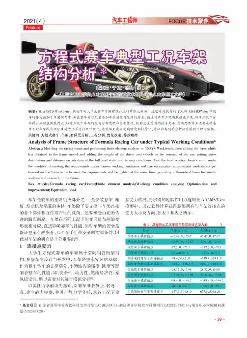
摘要:在ANSYS Workbench 模块下对大学生赛车车架建模并进行有限元分析。
通过等效载荷的方式将ADAMS/View 中获得的各力施加于车架模型中,并在整车质心位置添加车手质量与发动机质量。
通过对典型工况满载静止工况、转弯工况下分析得出分别在满载静止、转弯工况下车架的应力分布情况和变形情况。
检验总支反力的误差大小,在满足各种工况要求的条 件下对车架提出优化改进方法并进行尺寸优化,达到满足要求的同时更加轻量化,为以后类似的分析研究提供了理论依据。
关键词:方程式赛车;车架;有限元分析;工况分析;优化改进;等效载荷Analysis of Frame Structure of Formula Racing Car under Typical Working Conditions *Abstract : Modeling the racing frame and performing finite element analysis in ANSYS Workbench, then adding the force which has obtained to the frame model and adding the weight of the driver and vehicle to the centroid of the car, getting stressdistribution and deformation situation of the full load static and turning conditions. Test the total reaction force's error, under the condition of meeting the requirements under various working conditions and size optimization improvement methods are put forward on the frame,so as to meet the requirements and be lighter at the same time, providing a theoretical basis for similaranalysis and research in the future.*基金项目:山东省高等学校青创科技支持计划(2019KJB001);烟台职业学院校本科研项目(2020XBYB0⑷;烟台职业学院横向课 题(HX2020020)Key words : Formula racing car;Frame;Finite element analysis;Working condition analysis; Optimization and improvement; Equivalent load车架是赛车的重要组成部分之一,是安装悬架、座 椅、发动机及尾翼的主体,车架除了要支撑与车架连接 的各个部件相互作用产生的载荷,还要承受由轮胎传 递的路面激励。
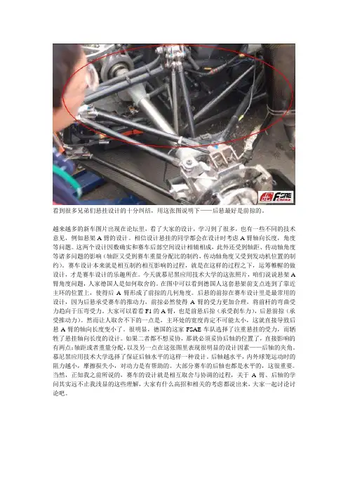
看到很多兄弟们悬挂设计的十分纠结,用这张图说明下——后悬最好是前掠的。
越来越多的新车图片出现在论坛里,看了大家的设计,学习到了很多,也有一些不同的技术意见,例如悬架A臂的设计。
相信设计悬挂的同学都会在设计时考虑A臂轴向长度,角度等问题。
这两个设计因数确实和赛车后部空间设计相辅相成,此外还受到轴距、传动轴角度等诸多问题的影响(轴距又受到赛车重量分配比的制约,传动轴角度又受到发动机位置的制约)。
赛车设计本来就是相互制约相互影响的过程,就是在这样的过程之下,运筹帷幄的做设计,才是赛车设计的乐趣所在。
今天就慕尼黑应用技术大学的这张照片,咱们说说悬架A 臂角度问题,人家德国人是如何取舍的。
在图中可以看到德国人这套悬架前支点连到了靠近主环的位置上,使得后A臂形成了前掠的几何角度。
后悬的前掠在赛车设计里是最常用的设计,因为后悬承受赛车的推动力,前掠必然使得A臂的受力更加合理,将前杆的弯曲受力趋向于压弯受力。
大家可以看看F1的A臂,也是前悬后掠(承受刹车力),后悬前掠(承受推动力)。
然而让人取舍不下的一点是,主环处的宽度肯定不可能太小,这就直接导致后悬A臂的轴向长度变小了。
很明显,德国的这家FSAE车队选择了注重悬挂的受力,而牺牲了悬挂轴向长度的设计。
如果二者都不想妥协,那就必须妥协后轴的位置了,直接影响的有两点:轴距或者重量分配,以及另一点在这张图里表现很明显的设计因素——后轴的夹角。
慕尼黑应用技术大学选择了保证后轴水平的这样一种设计。
后轴越水平,内外球笼运动时的阻力越小,摩擦损失小,对动力是有帮助的。
大部分赛车的后轴也都是水平的,这很重要。
当然,正如我之前所说的,赛车的设计就是相互取舍与协调的过程,关于A臂、后轴的学问其实远不止我浅显的这些理解,大家有什么高招和相关的考虑都说出来,大家一起讨论讨论吧。
一个后轮主销,让我们看到差距有多大。
制动器选择、主销结构、球头选择、调整与锁紧机构。
前一段时间和BOXSTER聊天,他给簧下质量一个很好的比喻:“车轮上的重量就如同一个跑步运动员,脖子上带条金链子都不嫌沉,鞋子则能轻几g轻几克。
大学生方程式赛车悬架系统的设计研究摘要:悬架是车架(或承载式车身)与车桥(或车轮)之间的一切传力装置的总称。
一般由弹性元件、减震器和导向机构组成,在多数的轿车和客车上还设有横向稳定杆。
悬架的功用是把路面作用于车轮上的垂直反力(支承力)、纵向反力(驱动力和制动力)和侧向反力以及这些反力所造成的力矩都传递到车架(或承载式车身)上,保证汽车的正常行驶。
关键词:悬架系统;刚度;横向稳定杆;计算1.悬架的设计要求具有合适的衰减震动的能力;保证汽车具有良好的操纵稳定性;汽车制动或加速时,要保证车身稳定,减少车身纵倾,转弯时车身侧倾角要合适;结构紧凑、占用空间尺寸要小;安装方便并易于调整;尽可能的传递车身与车轮之间的各种力和力矩,保证强度同时做到轻量化。
2.整车参数整车质量m(包含车手60):300kg,前后轴距L:1550mm,前轮距B1:1250mm,后轮距B2:1200mm,质心高度h:300mm,前悬静态侧倾中心高度Z RF:15m,后悬静态侧倾中心高度Z RR:25mm,前后载荷比:45:55。
3.设计计算3.1 偏频选定汽车偏频是指汽车前、后部分车身的固有频率(用和表示)。
不同范围的偏频适用于不同类型、不同用途的汽车,一般的取值范围:普通轿车0.5~1.5,适中负升力赛车1.5~2.0,高负升力赛车3.0~5.0以上。
FSAE赛车的前后悬架偏频范围在2.4~3.5,且偏频的大小决定了悬架刚度的大小,影响赛车的舒适性和操纵性能。
综上考虑,前后悬架偏频定为:,。
3.2 悬架刚度计算(1)质心到侧倾轴线的距离计算:图1 横向载荷转移几何如图1所示,,,。
(2)悬架乘适刚度计算:(赛车簧下质量为60kg)赛车簧上质量,前轴左右单侧车轮的簧上质量,后轴左右单侧车轮的簧上质量,前轴左右单侧悬架的乘适刚度,后轴左右单侧悬架的乘适刚度。
(3)前后悬架传动比计算:(轮胎刚度)前后悬架的车轮中心刚度,,前悬架弹簧刚度为,后悬架弹簧刚度为,前悬架传动比,后悬架传动比。

毕业设计说明书学院:机械工程系(专业):车辆工程题目:方程式赛车悬架系统设计分析毕业设计(论文)中文摘要目录1 绪论 (1)1.1 引言 (1)1.2 FSAE大学生方程式汽车大赛简介 (1)1.3 赛事意义 (4)1.4 课题的主要任务 (5)2 FSAE悬架设计 (6)2.1 FSAE底盘规则概况 (6)2.2 悬架概述 (8)2.3 悬架设计要求 (9)2.4 悬架结构的选型 (10)2.5 双横臂独立悬架导向机构的设计 (11)2.6 FSAE赛车悬架参数 (15)2.7 车轮定位参数 (23)2.8 弹性元件、减震器的选择与布置 (24)2.9 A臂材料与尺寸 (25)2.10 连接件及轴承的选择 (26)2.11 CAD图与CATIA三维实体图 (29)2.12 主要零件的受力分析 (40)3 方程式悬架的运动仿真 (45)3.1 ADAMS软件简介 (45)3.2 ADAMS基本模块 (46)3.3 前悬架模型的建立 (47)3.4 模型的仿真 (53)3.5 仿真曲线的后期处理 (60)结论 (66)参考文献 (67)致谢................................................. 错误!未定义书签。
1绪论1.1引言悬架是现代汽车上的重要总成之一[1],由于双横臂悬架有较好的运动特性,因此在越来越多的轿车的前悬上得到应用,特别是在赛车上,更是得到广泛运用,其设计好坏对操纵稳定性、平顺性和安全性有着重要的影响。
操纵稳定性不仅影响到汽车驾驶的操纵方便程度, 而且也是决定汽车高速安全行驶的一个主要性能[2]。
本文根据中国FSC大赛规则对赛车的悬架系统进行了设计与分析。
汽车的四轮定位决定了整车的运动性能,前转向轮的定位整合了转向与悬架系统的所有几何参数[3]。
悬架的运动学性能直接影响操纵稳定性等汽车使用性能,而正确的车轮定位参数能够使赛车的运动性能得到良好地发挥,同时还能够增加赛车的安全性与舒适性提高轮胎的使用寿命[4],减轻驾驶员的驾驶疲劳。
大学生方程式赛车悬架系统参数优化设计刘寅童,邢立轩,卢泳陵*同济大学【摘要】大学生方程式赛车当前已经风靡全球。
其设计形式可谓五花八门。
作为一款赛车,悬架系统对于其整车性能的影响不可忽视。
为了能够使赛车的操控性能最优化,对于不同的赛车,即使采用相同的悬架结构形式,也应该具有不同的设计参数。
本文将以自行设计的赛车为基础,针对赛道路况,设计及优化悬架系统参数,以使赛车能够达到较好的操控性和平顺性。
【关键词】大学生方程式赛车,悬架系统,侧倾中心,前轮外倾角,悬架刚度Optimization for the Suspension Parameters of Formula SAE CarLiu Yintong, Xing Lixuan, Lu YonglingTongji UniversityAbstract: Formula SAE has been already very popular among the young people globaly. The design has also been diversified. As a racing car, suspension system has a great effect on the performance of the car. As a result, a similar suspension structure on different car must has differenet parameters, to optimize the performance. In this article, the design was based on a self-built car and the parameters was optimized for circuit condition to improve the controlling and riding performance.Key words: Formula SAE, Suspension system, Roll center, Camber, Suspension stiffness 1 研究背景大学生方程式赛车系列赛事(Formula SAE)由美国汽车工程师协会(SAE International)创办于1979年。
FSC大学生方程式赛车悬架设计与研究FSC大学生方程式汽车悬架设计与研究摘要悬架的系统设计与优化,是汽车总体设计中极其重要的一个环节。
本设计以北京理工大学珠海学院FSC车队2020年赛车悬架系统的结构设计为研究目标,主要进行了几个方面的研究工作。
本设计结合赛事规则要求,先确定设计思路,对轮距、轴距、前后悬架立柱等相关部件进行计算与设计,分析车轮定位参数对赛车性能的影响,在确定采用不等长双横臂式悬架结构后,选择弹性元件、减振器、导向机构与其他元件的类型,确保其符合赛车悬架设计的相关原则,并利用CATIA软件对其中重要元件进行三维建模设计,最后,基于ADAMS仿真平台,建立赛车悬架的运动学仿真模型,对其进行仿真分析,得到悬架参数模型后,对初选参数进行结果分析,并利用ADAMS对悬架参数进行优化。
关键词:大学生方程式赛车;悬架系统;结构设计;仿真优化Design and Study of Suspension for a FSC CarAbstractThe design and optimization of suspension system is an essential part of the overall design for a race car. This design takes the suspension system of FSC race car designed by the race team ,which is from Beijing institute of technology, Zhuhai, as the research objective. The the design mainly work in several aspects. This design was based on the competition rules of FSC. The calculation of the wheel track and spread of axles as well as the design of some related components including the front and rear suspension column have been conducted after a clear idea of the design had been made. The next step is the analysis of wheel alignment parameters in order to make out whether it affects the performance of the car. When unequal-length wishbone suspension is selected, the paper chose the type of flexible components, absorder, guide mechanism and other parts, and make sure it in the line with some basic principles. After that, we established 3D model with the help of the software of CATIA. Finally, based on the simulation platform of ADAMS, the kinematics simulation model of racing car suspension was established, and the simulation analysis was carried out. After the suspension parameter model was obtained, the results of primary parameters were used to analyze, and the suspension parameters were optimized by ADAMS.Keywords: FSC Race Car; Suspension system; Design of Structure;Simulate and Optimize目录1绪论 (1)1.1本设计的目的与意义 (1)1.2FSC大赛概况 (1)1.3国内外方程式赛车悬架的研究现状 (2)1.3.1国外研究现状 (2)1.3.2国内研究现状 (3)1.4设计研究的主要内容 (3)1.5本章小结 (4)2悬架系统设计 (5)2.1设计原理与思路 (5)2.2悬架形式的确定 (7)2.3相关部件的设计与选型 (8)2.3.1轮辋与轮胎的选型 (8)2.3.2车轮定位参数 (8)2.3.3 轴荷比、轴距与轮距的设计 (9)2.3.4 悬架导向机构的设计 (10)2.3.5 性能参数的计算 (11)2.3.6 前后悬架立柱的设计 (13)2.3.7 减震器的选型 (13)2.3.8悬架基本参数 (15)2.4章节小结 (16)3 悬架三维建模与装配 (17)3.1悬架零部件的三维建模 (17)3.2悬架的装配 (18)3.3章节小结 (19)4 ADAMS悬架建模与仿真 (20)4.1悬架动力学建模 (20)4.2悬架仿真 (21)4.3仿真结果分析 (23)4.4章节小结 (25)5硬点坐标的优化 (26)5.1仿真结果优化 (26)5.2优化前后结果分析 (28)5.3章节小结 (31)6 结论 (32)参考文献 (33)致谢 (34)附录 (35)附录1英文文献原文 (35)附录2中文翻译 (43)附录3前悬架左耳片CAD二维图 (49)附录4前悬架左立柱CAD二维图 (50)1绪论1.1本设计的目的与意义悬架,作为汽车连接车架与车桥的传力装置,是现代汽车上的重要总成之一。
大学生方程式赛车车架设计摘要:为了保证赛车车架安全可靠性、操作稳定性,对车架进行各工况分析;为提高其燃油经济性,对车架轻量化设计分析。
本文采用CATIA三维软件对车架进行三维设计,利用有限元分析软件对车架进行模态分析,有效缩短整个车架设计与制造的时间;采用LMS Test. Lab振动测试软件对车架的模态进行测试,解决了车架与发动机及传动部件的共振问题。
同时,进行了人机工程实验数据采集,解决了车手驾驶易疲劳问题。
关键词:车架;有限元分析;人机工程;振动Abstract:In order to ensure the safety, reliability and operationalstability of the racing car frame, various working conditions of the frame are analyzed; In order to improve its fuel economy, the lightweight design of the frame is analyzed. In this paper, CATIA three-dimensional software is used for three-dimensional design of the frame, and finite element analysis software is used for modal analysis of the frame, which can effectively shorten the designand manufacturing time of the whole frame; Use LMS test Lab vibration test software tests the modal of the frame, and solves the resonance problem between the frame and the engine and transmission components. At the same time, the man-machine engineering experiment data collection is carried out to solve thedriver fatigue problem.Key words: frame; finite element analysis; ergonomic; vibration一、课题研究背景和意义中国大学生方程式汽车大赛自2010本土化以来,经过几年的学习与沉淀,不管是举办方或者是学生团队都有了蓬勃的发展,成绩喜人。
方程式赛车SAE制动和车架的介绍摘要本文是对方程式SAE(FSAE的)悬架和框架设计上的设计团队在UM的罗拉经验介绍。
的基本理论和设计这些系统的方法提出,使新的团队将能为他们的第一FSAE的设计基准。
例子我们会根据在UM -罗拉的1996 FSAE的条目。
简介方程式SAE是一个学生的竞争,由美国汽车工程师学会(SAE),其中学生设计,构建和竞争方程式风格的小赛车赞助。
本次比赛的基础是一个虚构的公司签订了合同的工程师建造一座小型方程式赛车组。
由于汽车是周末越野赛车打算,该公司已经制定了8,500元的最高成本。
比赛规则限制了赛车引擎的610cc与单一入口节流最大位移。
其他规则要求的汽车必须有一个最小为50mm轮旅行和轴距大于一千五百二十四毫米悬挂系统。
这款车还必须符合安全要求,如侧撞保护比赛分为静态和动态的活动。
静态活动包括成本分析,销售演示和工程设计。
比赛的动态部分是15.25米直径防滑垫,91.44米加速时,越野0.8公里,44公里耐力赛,和燃油经济性。
运行FSAE比赛的设立是为了提供一个当代大学生的教育经验,是类似的项目类型,他们将面对的工作队伍。
参加FSAE的,学生团体与从抽象的设计阶段项目,直到它完成。
工程设计,团队合作,项目管理,财务方面都被纳入一级方程式SAE的基本规则。
本文涵盖的悬挂和框架设计的一些基本概念,并强调了UM的罗拉设计时其1996年的暂停和框架的方法。
受部分涉及的基本设计参数,并提出具体的例子。
框架部分讨论如何实现与FSAE的设计约束妥协。
最后,设计部门提供了一个由UM的罗拉用于1996年赛车的设计方法的简要概述。
1996年完成队12日在工程设计活动,而整体成绩是77国参赛车队19了。
1 悬挂几何受几何部分集中的悬架设计的基本领域,并突出一些什么UM的罗拉设计团队1996年的赛车悬挂几何选择。
FSAE的悬浮工作在汽车动力主要是由于有限的转弯是由大小管辖的速度在赛道狭窄的领域。
毕业设计(论文)题目大学生方程式赛车设计(模具及卡具设计)2013年5月30日方程式赛车模具及卡具设计摘要本文依据大学生方程式汽车大赛FSAE赛事技术规则对大学生方程式赛车整体车架、悬架进行了模具及卡具设计。
在卡具设计当中不仅需要考虑赛车车架各杆件是否定位完全以及夹紧可靠,同时必须考虑支撑杆件的强度和刚度能否满足要求,最终还必须考虑焊接空间是否与支撑杆干涉。
在模具设计当中不仅要考虑凸、凹模的加工精度以及冲压机的选择,同时还必须考虑凸、凹模的强度和刚度。
本文在完全满足上述要求的前提下对模具及卡具进行了设计。
在模具及卡具设计之初,将方程式汽车大赛的有关规定和评分标准,作为后续模具及卡具设计的技术规范要求;为了达到卡具设计合理性的目的,本设计参考了湖南大学、天津大学以及部分国外大学的赛车模具及卡具。
进入设计阶段,本设计通过分析比较几种模具及卡具的结构形式,决定选择定位与夹紧一体化的卡具设计,采用压弯模制得对强度要求较高的主环。
然后依据技术规范、车架的最终尺寸确定了卡具及模具的结构形式和具体尺寸,。
再对模具及卡具进行受力分析,使各杆件能合理的定位、夹紧,使主环能满足强度和精度的要求,直至模具及卡具结构满足各个方面的要求。
关键词:FSAE,模具,卡具,建模,工艺分析FORMULE SAE—A MOLD AND FIXTURE DESIGNABSTRACTBased on equation FSAE car competition event technical regulations of university students for the college students formula overall frame, suspension for the mould and fixture design. In fixture design not only need to consider whether or not the car frame each bar of positioning and clamping completely reliable, at the same time must consider the strength of the support bar and stiffness can meet the requirements, the final must also consider whether the welding space interference with the support bar. During mold design should not only consider the machining precision of the convex, concave die and punch, also must consider the intensity of the convex, concave die and stiffness. In this paper, on the premise of fully meet the above requirements on the mould and fixture design.At the beginning of the mould and fixture design, the formula car contest regulations and criteria, as the follow-up mold and fixture design of the technical specification requirements; In order to achieve the purpose of fixture design rationality, the design reference of Hunan university, Tianjin university and some of the foreign car mold and fixture. Entered the stage of design, this design through the comparative analysis several kinds of mould and the structure of fixture, decided to choose integration of positioning and clamping fixture design, USES the bending molding of strength to demand higher main ring. Then according to specification, to obtain the final size of the frame the structure of the mould and fixture and the specific size, and set up in the frame models of the fixture. Stress analysis was carried out on the mold and fixture, make each bar can reasonable positioning, clamping, the main ring can meet the accuracy requirement of the strength and, until the mold and fixture structure meet the requirements of all aspects.Key words: FSAE, mould, fixture, modeling, process analysis目录第一章绪论 (1)§赛事简介 (1)§大赛性质 (2)§大赛理念 (2)§愿景与使命 (2)§组织结构 (3)第二章焊接卡具的设计 (4)§焊接的主要类型 (4)§点焊 (4)§凸焊 (4)§钎焊 (5)§二氧化碳焊 (5)§车用焊接卡具分析 (5)§焊接夹具的分类 (6)§无驱动夹具 (6)§气动夹具和手动夹具 (6)§焊接夹具的结构设计 (7)§六点定位原则在车身焊装夹具上的应用 (7)§焊装夹具设计原则 (8)§焊装夹具的基本要求 (8)§工艺分析 (9)§车架的分析 (9)§基准的选择 (9)§制定工艺路线 (9)§定位、夹紧元件的选择 (11)§定位元件及定位方式的选择 (11)§工件的夹紧及对夹紧装置的要求 (13)§定位误差的分析与计算 (13)§工件的夹紧 (14)§夹紧装置的设计原则 (15)§夹紧力确定的基本原则 (16)§减小夹紧变形的措施 (18)第三章模具的设计 (20)§模具的发展与现状 (20)§国内模具的发展与现状 (20)§模具CAD/CAE/CAM技术 (22)§零件工艺性分析 (23)§材料选择 (23)§结构分析 (23)§工艺分析 (24)§ U形件弯曲模结构设计 (25)§模具的整体结构 (25)§凸、凹模的结构和固定形式 (25)§模具零件的设计与计算 (26)§凸、凹模的间隙 (26)§弯曲力计算 (27)§凸模长度的确定 (28)§凹模尺寸的确定 (28)§冲压设备的选用 (29)§冲压设备主要技术参数 (29)§冲压力的计算 (31)§选择压力机 (31)§模具强度和刚度的计算 (32)第四章结论 (35)参考文献 (36)致谢 (37)第一章绪论§赛事简介Formula SAE 赛事由美国汽车工程师协会(the Society of Automotive Engineers 简称SAE)主办。
悬架零件强度分析
赛车的悬架在赛车的行驶安全中具有重要的作用,所以在对赛车的悬架进行
设计时,悬架的受力分析显得尤为重要。
通过对悬架的受力分析,可以对悬架的
安全性能进行评估,同时可以节约材料,使材料的使用更加合理。
在SolidWorks中完成悬架零部件的建模后,使用SolidWorks 力学分析模块Simulation对悬架零部件的强度和刚度进行校核。
赛车高速过弯和高速制动减速是赛车行驶过程中比较常见的两种工况,高速过弯时赛车将承受极大的离心力并发生横向载荷转移,而高速制动减速时赛车则承受极大的惯性力并发生纵向载荷转移,这两种工况下悬架各个零部件将承受比较大的动载荷。
分别是立柱、轮毂进行受力分析,因为这两个是悬架的主要受力部分。
通过建立SolidWorks 模型,并进入Simulation模块设置相应的单元的材料类型,设置夹持方式,施加载荷,然后进行网格划分,最后进行求解,可以得出最终的分析结果。
立柱模型
立柱材料属性
模型参考属性
名称: 7075-T6 (SN)
模型类型: 线性弹性同向性
默认失败准则: 最大 von Mises 应力
屈服强度: 5.05e+008 N/m^2
张力强度: 5.7e+008 N/m^2
弹性模量: 7.2e+010 N/m^2。
Error No. 1This picture shows a classic design error that all Judges hate, and is considered a "Mortal Sin". Every year several cars are presented like this as teams ignore the advice or directions they are given.The outer spherical bearings are threaded rod ends loaded in bending! The entire mass of the car, plus bump loads, weight transfer and brake torque are reacted to the chassis by bending the threaded shank of the lower joint. This is going to break! GTB! Do not do this!The upper rod end is being asked to react brake torque in bending. It is also being carried in single shear on top of the upright. These errors are not so serious, but still examples of poor design.The judges understand why teams do this. It makes camber adjustment easy, but there are better solutions. Teams will argue they have selected a rod end with sufficient bending capacity, but this argument will not hold with the judges. A Rod end with a sufficiently strong shank will be far too big and heavy, and as the thread roots are good stress raisers, the joint will probably crack and break anyway. In any case, we are talking about the Design Competition, and incorrect use of fasteners is not good design.Some teams may build a set of adjustable suspension arms like this for testing. It enables them to determine optimum camber (and/or caster) angles, but when their testing is complete, they build a more appropriate set of components for the competition.The inevitable consequence of bending rod end shanks is this!Design Error TwoOkay, time for this months Design Error. I want you to look at these pictures and see how many design errors you can see. The assembly looks quite good on first view, but a closer look shows many errors.Okay, where do I start?1. The rod ends are loaded in bending. (See last months column)2. They are in single shear.3. The upper outer hex bolts are threaded into the upright with no positive locking.4. There is no washer under the hex bolt head to stop the rod end body coming over thebolt head in the event of a failure.5. The steering arm is mounted with hex head bolts threaded into the upright with nopositive locking.6. The caliper mounting plate is sandwiched between the upright and the steering arm.7. It appears that the brake torque is fed to the upright by having the upright recessedinto the caliper mount8. The caliper is also retained by the front steering arm bolt.9. The brake rotor is attached to the hub by use of countersunk hex head bolts with nopositive locking.10. The assembly restricts access to these bolts so they cannot be checked for tightness.11. The very short stub axle shows that the distance between the hub bearings isinsufficient.There may be more (Stress raisers on the edge of the caliper plate recess?) Feel free to find more for me please.So, what looked okay at first glance was actually a disaster looking for a place to happen. I can promise you that if I see anything like this in Hockenheim next year, I will personally kick the butt of whoever is responsible (Or delegate someone else to do it if the designer is biggerthan me)Remember, I am still available to answer design questions from teams on orPat’s Design Errors No. 3Many Formula teams are not aware that the biggest single force generated in the car is the front brake torque. Unless a team uses inboard front brakes (Unlikely) they have to understand how to react that brake torque into the primary chassis structure via the suspension components.If you consider in simple terms what happens, it is easier to understand.When the brakes are applied, the stationary caliper attempts to lock itself to the rotor. The caliper mounts and upright must be properly designed to accept this force repeatedly without failure. This is particularly true of machined aluminium uprights.Similarly, the rotor mount and wheel hub must be designed for the job.Fig 1. Distorted front upright.It can be seen where the brake torque has overcome t he integrity of this CNC’d upright. A simple diagonal web instead of the horizontal webs seen here might have avoided this failure. But look at the other picture before accepting that advice.The load path from the upright to the chassis structure should direct and simple. As we discussed in DE1, feeding suspension and brake forces through threaded shafts in bending is not acceptable. Neither is chassis brackets that are flexible or poorly mounted. Judges have a good eye for this and will quickly appraise your design solution.Fig 2. Failed upright and brake spider.In this case, not only has the upright failed catastrophically, but the brake rotor spider has also failedIf you have a composite chassis structure, be prepared to show the judges proof of the effectiveness of your design.The problem at the rear of the car is usually not so critical as most cars feed the brake torque and the engine torque into the chassis inboard of the suspension, and if the brakes are mounted outboard, the torque generated is usually only about one third of the front wheel torque.Design Error FourWell, not really an error in design, rather an error in project management.This is the famous 2001 WWU 554cc V8. It used Kawasaki cylinder heads on a bespoke block with all internals and systems made by the team.The engine drove through a carbon fibre cased gearbox housing Honda gears and selectors. The transmission was also designed and built by the students.The engine made a mockery of the costing formula for engines and raised an enormous amount of interest at the event.But it all fizzled out to naught. So much effort had gone into the power train that the chassis left much to be desired.Then the engine could not be started at the event and so did not compete. Under the stresses placed on them by the project, the team had neglected to fit any form of starter!Probably the best example in FSAE history of a team totally forgetting the intent of the competition, still, they will always be remembered for their achievement!This months Design Error FIVEMore teams are making their own wheels. Usually they make or buy rims and then design and make an aluminium centre.This seems a pretty straightforward task, yet many teams obviously do not understand the loads applied to a wheel on a racecar.The shear loads across the interface between hub face and wheel is sometimes passed through the root of a thread on the wheel studs. This is particularly common where teams use high tensile bolts or Allen screws as wheel studs.The wheel should be centered on a spigot on the hub face. Some teams assume that using conical nuts will centre the wheel for them. Conical nuts will introduce stresses in a light alloywheel centre that may well cause a total failure of the wheel. This is a very public way to have a DNF and might well cause someone to get hurt. People have been injured by wheels coming off cars in competition.Wheels before and after failureAll the best suspension calculations are useless if wheel flex permits the to assume a positive camber attitude on the track under cornering loads.This picture shows the effect of wheel flex on camber.So, until next month, good luck with your car and team building exercises.This months Design Error sixJust to be different, this month I am going to talk about a piece of good design. This is not a Design Error, rather it is a very nice solution to hub and wheel mount design, although it may have one flaw.The reason for posting this is that I have been very critical of some hub designs. Having thread roots across the shear face between the hub and wheel, no spigot to centre the wheel on the hub and using tapered wheel nuts seating in aluminium wheel centres are all evidence of poor design.I don’t know where this hub design comes from, but I like it.As can be seen, the shear load at the hub face is taken through a small shank on the wheel stud. The wheel nuts are sleeve nuts designed to tighten against the steel hub face whilst applying a measured amount of clamping force to the wheels. The flat washer prevents the nuts galling the wheel centre (especially important with magnesium wheels).The flaw? What about a centering spigot for the wheel? Well, I hope that is machined into the wheel and sits into the recess in the hub face. If the wheels are being centered by the wheel nuts, then this design is not so nice.Another nice feature is that the tripod recess is machined right through the live hub. This allows the driveshaft length to be as long as possible, therefore reducing angularity losses, whilst at the same time accepting any driveshaft end plunge caused by suspension movement.That is enough for this month. Hopefully teams will be back at work getting ready to build their new car. Good luck to all and I look forward to seeing you all in August.This Months Design Error SevenObviously, my Design error of the month has to relate to a misunderstanding of one of Newton’s Laws, in this case the Third Law.Look where the bell-crank and spring loads are being reacted! Judges look at a design like this, they can see the load paths and they eliminate the car from the Design Finals!Now take a look at this load path. Isaac Newton turned in his grave just a couple of minutes before the frame broke.。