Performance Characterization of SPEC CPU Benchmarks on Intel's Core Microarchitecture based
- 格式:pdf
- 大小:110.46 KB
- 文档页数:8


材料化工专业英语生词本Synthesis 合成Properties 性质Anatase 锐钛矿rutile 金红石brookite板钛矿Crystalline 结晶的nanometer 纳米nanorods/wires纳米棒/线nanocrystals 纳米晶体nanocarriers 纳米载体nanoparticles (NPs)纳米颗粒nanocomposite纳米复合Hierarchical Nanostructures 分层纳米材料titanium dioxide TiO2 polymorphs of titania 多晶型 TiO2 amorphous 非晶的Three-dimensional 3Dfacile and controlled 容易控制hydrothermal 热液的annealing 退火investigate 调查,研究radially 放射状地petal 花瓣thin 薄的thick 厚的morphology 形态The surface area 表面积adsorption-desorption 吸附-解析(ads)orption isotherms 吸附等温线the Brunauer-Emmett-Teller BET 比表面积测试法specific surface areas 比表面积sensitivity 灵敏、灵敏性ethanol 乙醇、酒精ethylene glycol 乙二醇EG化学式C2H6O2分子式:HOC2H4OHsensor 传感器、感应器solar cells太阳能电池biosensors 生物传感器catalyst 催化剂Catalysis 催化photo-catalytic 光催化的inorganic 无机的objective 目标optimize 使完善、使优化optical 光学的magnetic 磁的application 应用bandgap 带隙transition metal oxides 过渡金属氧化物paint 油漆、颜料gas sensor 气敏元件、气敏传感器Li-ion battery 锂离子电池Electrochromic 电致变色的Photochromism 光致变色macro/mesoporous materials 宏/介孔材料CVD(Chemical Vapor Deposition, 化学气相沉积)Anodic 阳极的hydrothermal method 水热法Template 样板、模板oriented attachment 定向附着primary nanoparticle 初级纳米粒子anisotropic非等方性的、各向异性的capping agents 盖髓剂kirkendall effect柯肯达尔效应tetragonal structure 四方结构photovoltaic cells 光伏电池smart surface coatings 智能表面涂层single-phase 单相precursor 先驱、前导Herein 在此处、鉴于、如此 Nanoflakes 纳米片metal-enhanced fluorescence 金属增强荧光fluorophores 荧光团The Royal Society of Chemistry 英国皇家化学学会ESI (Electronic Supplementary Material) 电子补充材料 Innovative 创新的 Polymer 聚合物 Chemical 化学品 Silica 硅 FITC (fluorescein isothiocyanate )荧光异硫氰酸酯EiTC ( Eosin isothiocyanate ) 异硫氰酸曙红Fluorescence spectra 荧光光谱 control sample 对照样品 Dissolve 溶解Characterization 表征 analytical grade 分析纯 ethanol 乙醇ethylene glycol 乙二醇 ammonia aqueous solution (28 wt %)氨水溶液(100公斤里含28公斤) acetone 丙酮分子式:C3H6O 简式:CH3COCH3EtoH 乙醇 ( PS :Et 代表乙基CH3CH2- Me 代表甲基CH3-)TEOS (tetraethyl orthosilicate ) 原硅酸四乙酯the TEOS concentration TEOS 浓度 CTAB (hexadecyltrimethylammonium bromide ) 十六甲基溴化铵The CTAB surfactant CATB 表面活性剂Sinopharm Chemical Reagent Co. 国药集团化学试剂有限公司Polyvinylpyrrolidone (PVP, Mw = 55000) 聚乙烯吡咯烷酮(PVP ,MW = 55000=兆瓦,百万瓦特(megawatt))Rhodamine B (Rh B) 玫瑰精,若丹明B poly(allylamine hydrochloride) (PAH, Mw = 56000) 聚(烯丙胺盐酸盐) Deionized water 去离子水PAH ( polycyclic aromatic hydrocarbon )多环芳族烃 Via 经由、通过the three-neck flask 三颈烧瓶 oil bath 油浴precipitate 沉淀centrifugation 离心分离 rpm 每分钟转数 core-shell 核-壳a surfactant-templating sol-gel approach 表面活性剂模板溶胶 - 凝胶法homo-dispersed solution 均聚物分散夜agitate 搅拌ultrasonically and mechanically 超声波地、机械地solvent extraction method 溶剂萃取法reflux 回流an impregnation method 浸渍方法 vial 小瓶 dilute 稀释composite 合成物、复合物TEM (Transmission electron microscopy )透射电子显微镜copper grids 铜网carbon films 碳膜SEM(Scanning electron microscopy)扫描电子显微镜Spray 喷FESEM(Field-emission scanning el ectron microscopy)场发射扫描电子显微镜LCSM(Laser confocal scanning microscopy )激光共聚焦扫描显微镜X-ray diffraction (XRD) X 射线衍射X-ray diffractometer X射线衍射仪Nitrogen 氮Micromeritcs n. 微晶(粒)学,粉末工艺学;粉体学degas除去瓦斯vacuum 真空BET(The Brunauer-Emmett-Teller) pore volume 孔体积spectrofluorometer 荧光分光剂spectrophotometer分光光度计bandpass 带通PMT voltage (Photomultiplier Tube)光电倍增管电压Confocal luminescence images共聚焦荧光图像Silver 银silica spacer 硅垫片fabricate制造; 伪造; 组装; 杜撰the metal-enhancedMEF(the metal-enhanced fluorescence )金属增强荧光Fluorescence quenching 荧光猝灭FRET (Fo¨rs ter resonance energy transfer )福斯特共振能量转移Optimization 最佳化; 最优化excited-state 激发态plasmon 等离子基元quantum yields 量子产率quantum dots 量子点resonance n.共振,共鸣, 反响, 回声donor–acceptor pairs 给体- 受体对proximity 接近efficiency 效率the transfer distances 传输距离deposite 被沉淀,存放plastic planar substrate塑料平面基板photoluminescence (PL)光致发光luminescent 发光的single nanoparticle sensing单一纳米粒子传感dielectric电介质; 绝缘体adj.非传导性的RE complexes稀土复合Polyelectrolytes聚合高分子电解质Electrolyte电解质Multilayer 多层Concentric 同中心的functionalized organic molecules 官能有机分子conjugation 结合,配合tedious and fussy繁琐和挑剔obstacle n.障碍, 阻碍, 妨害物controlled release,控释detection and probe applications 检测和探头应用general一般的; 综合的; 普通的universal普遍的, 通用的, 全体的Inspired 启发Possess 拥有Pore 孔drugs and macro-molecules 药物和大分子herein在此处, 鉴于, 如此Ag@SiO2@mSiO2(Ag-core@silica-spacer@mesoporo us silica )The preparation procedure编制程序Water-soluble可溶于水的; 水溶性的,微溶于水A high-temperature solvothermal method一种高温溶剂热法Solvent 溶剂Esolution 分辨率twinned structures 联动结构,孪生结构concentration 浓度tune 调节is ascribed to 归因于dilute稀释spherical morphology 球形形态type-IV curves IV型曲线polyelectrolytesodium chloride食盐; 氯化钠plasmonic absorption电浆吸收an intuitive way 以直观的方式unambiguous 不含糊的, 明白的demonstrate 证明antibody 抗体NSF(National Sanitation Foundation)美国国家卫生基金会PRC(The People's Republic of China)中华人民共和国Shanghai Municipality上海市Shanghai Leading Academic Discipline Project上海重点学科建设项目Tri-functional hierarchical三官能分层DSSCs(dye-sensitized solar cells)染料敏化太阳能电池DOI(Digital Object Unique Identifier)是一种数字对象标识体系acid thermal method 酸热法titanium n-butoxid正丁醇钛acetic acid乙酸、醋酸kinetic 动能light-scattering 光散射photoelectrodes 光电极opto-electronic 光电的calcine煅烧short-circuit photocurrent density短路光电流密度open-circuit voltage开路电压compared to 相比,把什么比作什么electron 电子recombination rates 重组率oxide 氧化物inorganic 无机的sub-microspheres 亚微球beads珠子To date 迄今a ruthenium complex light-harvester钌络合物的光收割机volatile 挥发性的photoanode光阳极superior 好的,卓越的photons 光子photovoltaic performance光伏性能In addition to 除。
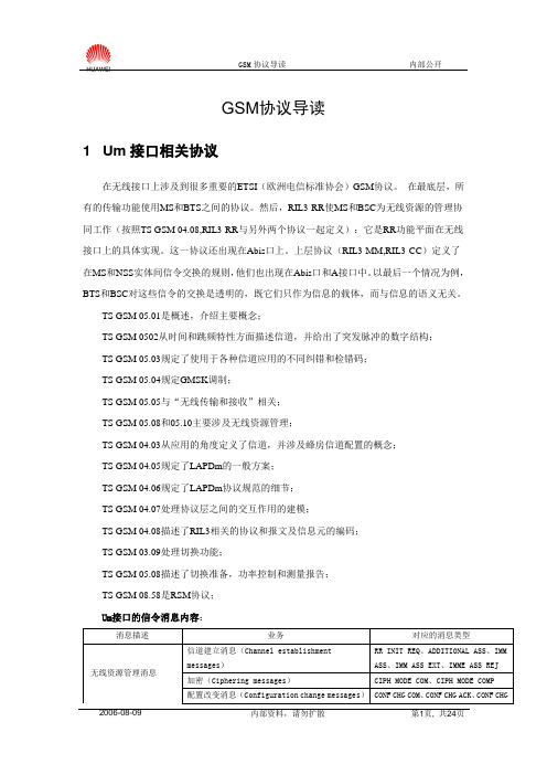
GSM协议导读1 Um接口相关协议在无线接口上涉及到很多重要的ETSI(欧洲电信标准协会)GSM协议。
在最底层,所有的传输功能使用MS和BTS之间的协议。
然后,RIL3-RR使MS和BSC为无线资源的管理协同工作(按照TS GSM 04.08,RIL3-RR与另外两个协议一起定义):它是RR功能平面在无线接口上的具体实现。
这一协议还出现在Abis口上。
上层协议(RIL3-MM,RIL3-CC)定义了在MS和NSS实体间信令交换的规则,他们也出现在Abis口和A接口中。
以最后一个情况为例,BTS和BSC对这些信令的交换是透明的,既它们只作为信息的载体,而与信息的语义无关。
TS GSM 05.01是概述,介绍主要概念;TS GSM 0502从时间和跳频特性方面描述信道,并给出了突发脉冲的数字结构;TS GSM 05.03规定了使用于各种信道应用的不同纠错和检错码;TS GSM 05.04规定GMSK调制;TS GSM 05.05与“无线传输和接收”相关;TS GSM 05.08和05.10主要涉及无线资源管理;TS GSM 04.03从应用的角度定义了信道,并涉及蜂房信道配置的概念;TS GSM 04.05规定了LAPDm的一般方案;TS GSM 04.06规定了LAPDm协议规范的细节;TS GSM 04.07处理协议层之间的交互作用的建模;TS GSM 04.08描述了RIL3相关的协议和报文及信息元的编码;TS GSM 03.09处理切换功能;TS GSM 05.08描述了切换准备,功率控制和测量报告;TS GSM 08.58是RSM协议;Um接口的信令消息内容:2 Abis接口相关协议Abis接口由一系列规范约定组成,这些规范包括以下方面的内容:•物理电气参数•信道结构•信令传输规程•配置和控制规程•操作和维护支持Abis 接口的相关协议如下:GSM 08.52,给出Abis接口其余规范的基本原理和原则,并给出BSC和BTS在业务功能上的功能分割。
Keysight TechnologiesE5080A ENA Vector Network Analyzer - 9 kHz to 4.5/6.5/9 GHzThe Next-Generation ENAThe Keysight E5080A is the next-generation RF vector network analyzer (VNA), providing best-in-class performance, flexible functionality and advanced usability for testing antennas, filters, cables, balanced/differential components, amplifiers and mixers. With its intuitive, touch-based interface, the E5080A is designed to help users streamline their measurement flow and achieve better results in less time. This new instrument implements a converged platform that leverages the best attributes of the ENA and PNA families. The E5080A sets the new standard in RF component testing for both R&D and manufacturing environments. The E5080A offers comprehensive functionalities for measuring active and passive components such as amplifiers, mixers, filters, antennas, cables, and many more. It builds on the over 45-year legacy of excellence in network analysis and 75-year electronic test and measurement experience.Best-in-Class PerformanceWide dynamic range152 dB (typical, 3 Hz IFBW)Fast measurement speed 3 ms (401 points, uncorrected)Low trace noise0.0005 dBrms (typical, 10 kHz IFBW)High temperature stability0.005 dB/°C (typical)Wide source power range–90 to +15 dBm (spec)The E5080A provides wide dynamic range from 9 kHz. More than 10 dB better dynamic range than E5071C enables to measure high-blocking DUTs such as filters accurately and improve measurement speed using wider IF bandwidth (IFBW). The unparalleled measurement speed compared to competitor products maximizes the test throughput in production line.Extremely low trace noise helps minimize errors and associated test margin when measuring low-loss devices such as filter pass-bands.The E5080A is designed to have the minimum temperature drift against variation of environment temperature. The superior measurement stability helps high-volume manufacturers minimize calibration time and associated downtime.152 dBIntuitive and Flexible Operations with Modern User InterfaceThe E5080A integrates a high resolution display with a touch screen, which provides a crisp view and easy access to alldata and traces. This enhanced user interface allows intuitive operation and helps you set up complex measurements quickly.The E5080A is designed to help users streamline their measurement flow. Measurement flow proceeds from right to left: front panel keys, touch-activated softkeys with tabs, and touch-driven trace displays and windowsEasy access to frequently used functionsThe tabbed soft panel enables you to access the analyzer’s major functions within a few steps. Your frequently used softkeys can be registered to the Favorite menu. A long touch on the screen activates the Context Popup menus, and these present the most relevant choices without needing to access the softkeys. Direct access to essential features through the toolbarMeasurement traces, channels, and windows can be quickly added by pressing the icons on the toolbar. The list of icons is customizable depending on your preference.Flexible traces and windows layoutThe layout of traces and windows can be flexibly allocated with intuitive drag-and-drop operations. Or the layout can also be changed by using the softkeys that split or combine traces and windows in a single action.Magnifying the displayWith multi-touch or single-touch gestures, you can magnify thedisplayed area on the screen.Figure 3. Customizable toolbar menusFigure 2. Tabbed soft panel and popup menuFigure 5. Multi-touch magnificationFigure 4. Drag-and-drop for traces/windowsStreamline Your Measurements with Advanced UsabilityThe E5080A’s advanced usability simplifies the measurement setup tasks, and its flexible display capabilities give excellent visibility of the measurement data.Quick setups using dialog menus and Copy ChannelA variety of dialog menus assist you in making complex measurement setups easily. The quick start dialog gives the templates of display layouts for typical measurement applications, and the subsequent sweep setup dialog completes necessary stimulus settings in a single page. Moreover, once you have completed making the setup for one channel, you can copyit to other channels by using the copy channel function. This significantly reduces the time required for making multi-channel measurement setups.Tabbed SheetThe tabbed sheet function allows you to split the measurement display into multiple pages within a single instrument state. Complicated multi-channel measurement data can be easily observed by splitting the channels into the sheets. The active sheet can be switched not only with the touch or mouse operations but with the Prev/Next hardkeys on the front panel. This is useful for manufacturing applications such as the BTS filter tuning where the hardkey operation is preferred.Flexible marker capabilitiesYou can place up to 15 markers per trace. For better visibility,the locations of the marker lists are flexibly movable, and the number of decimal places can be changed as you like. In addition, a variety of marker search functions are available, including the single or multiple max/min/peak/target search, the bandwidth/notch search, and the gain compression search. Figure 7. Displaying four channel data using Tabbed Sheet Figure 6. Quick Start dialogsFigure 8. Up to 15 markers per traceThe E5080A combines the highest RF performance with powerful analysis capabilities that enables you to address a variety of applications and increase test efficiency.Powerful, fast and accurate automatic fixture removal (S96007A)Accurately removing the effects of the fixture is required to get a good measurement of the DUT. Automatic fixture removal adds a powerful application wizard to guide you throughcharacterizing a fixture and removing it from the measurement. Complicated modeling in EM simulation software or multiple calibration standards fabricated on board is no longer needed to characterize and remove a fixture.–Easiest way to remove fixture effects from non-coaxial device measurements–Extract fixture S-parameters from 2x thru or one-port measurements–Step-by-step wizard to characterize your fixture and remove it from your measurementsAccurate characterization of mixers and converters (S96082A)Frequency offset mode is available to set the E5080A’s source frequency independently from where the receivers are tuned for mixer measurements. Scaler mixer calibration (SMC) provides the most accurate conversion loss/gain measurements by combining two-port and power calibration. Vector mixer calibration (VMC) provides measurements of match, conversion loss/gain and group delay. Input and output mismatch correction reduces ripple and eliminates the need for attenuators.–Intuitive user interface –Frequency-offset sweep–Match-corrected conversion loss measurements–Controls external signal generators and power metersFast, accurate gain compression versus frequency measurements of amplifiers (S96086A)S96086A makes it easy to characterize compression over the DUT’s operating frequency range with extreme speed and ac-curacy, and with a simple setup. Instead of a linear power sweep with many points, the S96086A uses an adaptive algorithm to find the desired compression point at each frequency with just a few power measurements, thus significantly reducing test times. –Fast and convenient measurements with SMART Sweep–Complete amplifier with 2-dimensional (2D) sweeps, choice of sweep frequency per power, or sweep power per frequencyE5080A Innovative ApplicationsFigure 9. Automatically characterizing test fixtureFigure 10. Intuitive wizard for configuring mixer/frequency converter measurementsFigure 11. Gain compression analysis of amplifierPinFrequencyGainCompression pointIteration pointAdvanced Calibration ToolsCalibrating network analyzers is critical for high accuracy measurements. The E5080A supports all common calibration methods for coaxial DUTs, waveguide DUTs and DUTs in test fixtures, on printed circuit boards (PCB) and on wafers. Thebuilt-in capabilities include advanced calibration methods and a new “basic calibration” feature that can simplify the calibration processes.TRL/LRL/TRM/LRM calibration (Through, Reflect, Line, Match) for on PCB and on-wafer measurements.Unknown Thru (SOLR) calibration for non-insertable devices.Source Power Cal for amplifier measurements, and offers advanced techniques such as power cal using the analyzer’s receiverQuick SOLT (QSOLT) reduces the number of correction standards and calibration steps for multiple ports calibration.Electronic calibration (ECal) modules offer accurate calibration with simple one-connection operation.Basic CalThe E5080A offers a variety of calibration menus and you can choose an appropriate menu depending on the complexity of your calibration methods. The Basic Cal dialog is a very simple calibration UI providing all the calibration buttons in the same dialog page. This calibration menu is suitable for performing relatively simple calibrations such as the basic SOLT cal. Advanced calibration methodsCal WizardThe E5080A also offers wizard-type calibration menus for complicated calibrations. The Smart Cal guides all the operation steps of the calibrations with the wizard menu. This calibration menu is suitable for performing complicated calibrations suchas mixed-connector cal, and the combination of the SOLT cal and the source/receiver power cals. The Cal All is the advanced wizard function of the Smart Cal. This calibration menu guides the calibrations of multi-channel measurement setups at minimal steps.Cal Plane ManagerThe Cal Plane Manager allows you to characterize the adapters, test fixtures, or probes to the S2P data, and mathematically de-embed them for improving the measurement accuracy at the DUT planes. This function also provides the capabilities for modifying the existing S2P files, such as reversing the port order of the S2P file and cascading two S2P files.Fixture simulatorThe fixture simulator offers functions for simulating fixtures and adapters such as embedding/deembedding, port matching, impedance transformation and port extensions.Figure 12. Basic CalFigure 13. Fixture simulatorExtend the Power of the E5080A ENA Measurements with up to 40 portsThe combination of the 4-port E5080A and E5092A configurable multiport test set offers a comprehensive multiport solution. Depending on your test requirements, you can flexibly build the test port configurations by changing the front jumper connections of up to two E5092A test sets. The measurement wizard assistant software (S93790A) simplifies complicated setup and calibration processes for multiport device tests with the E5080A and E5092A.CalPod calibration-refresh modulesKeysight provides a unique way to quickly and easily refresh a calibration at the push of a button, without removing the DUT, and without the physical connection of standards. CalPods are particularly useful in thermal or thermal-vacuum chambers for removing environmental effects from your measurement results due to temperature changes of cables, connectors, and adaptors, or for removing variations due to cable movements or variations in switch matrices.BenchVue SoftwareKeysight BenchVue software for the PC eliminates many of the issues around bench testing. By making it simple to connect, control instruments, and automate test sequences so you can quickly move past the test development phase and access results faster than ever before with just a few clicks. A dedicated Network Analyzer App, available with BV9001B, allows you to quickly configure the most commonly used measurements and setups. Rapidly build custom test sequences with the integrated Test Flow App to automate and visualize test results without the need for instrument programming. BenchVue supports hundreds of Keysight instrument types and models all from one easy to use software platform. Control, Automate, Simplify with BenchVue.–Easily control, get screen captures and trace data–Capture measurements from your network analyzer in asingle click–Automate common network analyzer controls andmeasurements as quickly as using your front panelFigure 14. Multiport configuration with E5080A and E5092AFigure 15. CalPods refresh a calibration without removing your DUT Figure 16. BenchVue: PC control, capture screen images or trace data, andbuild automated tests in minutesFigure 18. The E5080A’s state file converter helps you easilytransfer your tests with the E5071CFigure 17. Code emulation mode for legacy vector network analyzersCompatibilityThe E5080A shares a common software platform with all members of the latest PNA family that makes it easy to choose just the right level of performance to match your budget and measurement needs. This commonality guarantees measurement consistency and repeatability and a common remote-programming interface across multiple instruments in R&D and manufacturing.The E5080A offers the E5071C code emulation mode which interprets the SCPI commands of the E5071C. This allows for instrument emulation and backward code capability enabling a seamless drop-in replacement in your automated test environment and minimizing transition risks. State files created using the E5071C can be converted and recalled with the E5080A. The E5080A also supports the code emulation mode for the legacy 8753 series network analyzers.This compatibility means that you can easily make the transition to the E5080A while leveraging your investment and expertise in test software. The test software from R&D can be effortlessly transferred to manufacturing which helps you maintain past efforts, enhance current designs, and accelerate future innovations.Extend the Power of the E5080A ENA (continued)E5080A Front and Rear PanelsFlexible, modern user interface: front panel keys tabbed soft panel, pulldown menus, customizable toolbar, right-click shortcuts, drag-and-drop operation and 12.1’’ touch screenState-of-the-art calibration capabilitiesContext sensitive built-in help10 MHz reference Quick access for Ecal and other USB devicesUp to 15 markers per trace GPIB for remote operation Aux inputs for DC measurements200 measurementchannels and unlimited traces Sweep Setup and Quick Start enables easy setupUndo/Redo cancels or restores the previous entriesHandler I/O for external device controlLAN and device-side USB provide alternatives to GPIB for remote programmingRemovable solid-state drive for secure envi-ronments (optional)Maintain data securityThe removable solid-statedrive makes it easy to move the instrument from one location to another.E5080A Key Specs & Features (Comparison with E5071C)100 kHz to 4.5/6.5/8.5 GHz, with bias-tees Test port 2 or 4-port, 50 Ω 2 or 4-port, 50 ΩDynamic range(at max source power)135 dB (spec, 10 Hz IFBW)152 dB (typical, 3 Hz IFBW)123 dB (spec)Trace noise0.0015 dBrms (spec, 10 kHz IFBW)0.0005 dBrms (typical, 10 kHz IFBW)0.003 dBrms (spec, 70 kHz IFBW) Stability0.005 dB/°C (typical)0.005 dB/°C (typical) Measurement speed(401 pts, 200 MHz span, uncorrected)3 ms7 msSource power–90 to +15 dBm (spec)–110 to +17 dBm (typical)–55 to +10 dBm (spec)NOP Max 100,001Max 20,001Channels200160Markers15/trace9/traceMeasurement parameters S-parameters (single-ended, mixed-mode), Absolutepower S-parameters (single-ended, mixed-mode), Absolute power, TDR and TDT parameters1Software capabilities Automatic fixture removal, time-domain analysis,frequency offset mode, scalar & vector mixer/converter measurement, gain compression measure-ments, measurement wizard assistant Time-domain analysis, frequency offset mode, scalar & vector mixer/converter measurement, measurement wizard assistant, enhanced time-domain analysisOther major software capabilities Fixture simulator, Equation editor, PMAR (powermeter as receiver)Fixture simulator, Equation editor, External test set mode2Automation Remote control with SCPI commands, 8753/E5071C-code emulation, BenchVue Remote control with SCPI commands, Built-in VBA 8753 code emulation, BenchVueMultiport test set E5092A E5092A, E5091A3Display12.1 inch10.4 inchBox height6U5UOther major hardware capabilities High stability oven (option), Bias tees, DC input ports High stability oven (option), Bias tees, DC inputports, Probe power1. Optional capabilities2. Assigns 4 test ports as direct source/receiver ports, S, R, A, and B.3. Discontinued test set, Dec. 2014 EOS.For more detailed information, refer to E5080A Data Sheet.LiteratureE5080A EVector Network Analyzer ENA Series, Data Sheet, 5992-0291ENE5080A Vector Network Analyzer ENA Series, Configuration Guide, 5992-0292ENKeysight Technologies Network Analyzer Selection Guide, 5989-7603ENWeb Resources/find/ecal/find/mta/find/multiport/find/benchvue11 | Keysight | E5080A Vector Network Analyzer ENA Series - Data SheetThis information is subject to change without notice.© Keysight Technologies, 2016, 2017Published in USA, July 12, 20175992-0290ENFor more information on KeysightTechnologies’ products, applications or services, please contact your local Keysight office. The complete list is available at:/find/contactus Americas Canada (877) 894 4414Brazil 55 11 3351 7010Mexico001 800 254 2440United States (800) 829 4444Asia Pacific Australia 1 800 629 485China800 810 0189Hong Kong 800 938 693India 1 800 11 2626Japan 0120 (421) 345Korea 080 769 0800Malaysia 1 800 888 848Singapore 180****8100Taiwan0800 047 866Other AP Countries (65) 6375 8100Europe & Middle East Austria 0800 001122Belgium 0800 58580Finland 0800 523252France 0805 980333Germany ***********Ireland 1800 832700Israel 1 809 343051Italy800 599100Luxembourg +32 800 58580Netherlands 0800 0233200Russia 8800 5009286Spain 800 000154Sweden 0200 882255Switzerland0800 805353Opt. 1 (DE)Opt. 2 (FR)Opt. 3 (IT)United Kingdom0800 0260637For other unlisted countries:/find/contactus(BP-6-20-17)/go/quality Keysight Technologies, Inc.DEKRA Certified ISO 9001:2015Quality Management SystemEvolving Since 1939Our unique combination of hardware, software, services, and people can help you reach your next breakthrough. We are unlocking the future of technology.From Hewlett-Packard to Agilent to Keysight.myKeysight/find/mykeysightA personalized view into the information most relevant to you.Keysight Services/find/serviceKeysight Services can help from acquisition to renewal across your instrument’s lifecycle. Our comprehensive service offerings—one-stop calibration, repair, asset management, technology refresh, consulting, training and more—helps you improve product quality and lower costs.Three-Year Warranty/find/ThreeYearWarrantyKeysight’s committed to superior product quality and lower total cost of ownership. Keysight is the only test and measurement company withthree-year warranty standard on all instruments, worldwide. And, we provide a one-year warranty on many accessories, calibration devices, systems and custom products.Keysight Assurance Plans/find/AssurancePlansUp to ten years of protection and no budgetary surprises to ensure your instruments are operating to specification, so you can rely on accurate measurements.Keysight Channel Partners/find/channelpartnersGet the best of both worlds: Keysight’s measurement expertise and productbreadth, combined with channel partner convenience.。
Introduction to GPCColumns, Distributions,Sample Prep., Calibration,What’s NewPolymer Analysis TechniquesHigh Performance Liquid Chromatography (HPLC) (mainly Size Exclusion Chromatography, SEC)Mass Spectroscopy (MS)Thermal Analysis (TA)Rheometry, Nuclear Magnetic Resonance spectroscopy (NMR), Fourier Transform Infrared spectroscopy (FTIR)Introduction to GPC OutlineWhat is GPC?GAP of AdditivesWhat’s New?What is GPC?▪Gel Permeation Chromatography (GPC) separates samplemolecules based upon their relative size in solution▪Size Exclusion Chromatography (SEC)▪Gel Filtration Chromatography (GFC)▪GPC is an isocratic mode of separation▪GPC is well-suited for polymer analysis –provides a “molecularweight distribution”Particles arePorous, rigidpolymericmaterialsBig ones are not sloweddown because they aretoo big to go into thepores, so they elute firstWhat is GPC?▪The elution profile represents the molecular weight distribution based upon the relative content of different molecular weights…▪Based on size in solution Elution Volume (retention time)largest smallest Mn Mw Mz Mz+1B ig O nes C ome O ut F irst M o l e c u l a r W e i g h tSome definitionsMolecular weight averages are used to provide numerical differences between samples –Mn: Number average molecular weighto At this point in the curve the number of molecules in the sample to left is equal to the number of molecules to the right–Mw: Weight average molecular weighto At this point in the curve the weight of the molecules to the left is equal to the weight of the molecules to the right–Mz and Mz+1: these values are calculated based on molecular weight and abundance (obtained by ultracentrifugation and GPC software computation)o The values are used for “comparison” purposes•Known samples to unknown samplesThese averages are statistical moments calculated from the molecular weight distribution curveMolecular Weight AveragesGPC Delivers all MW information with one experiment GPC calculates the MW distributionof the polymer; this distribution canbe measured for:–Mn can affect a polymer’s brittleness,flow and compression properties.–Mw is related to strength properties,and impact resistance–Mz is related to elongation andflexibility, (Gumby -rubber)–Mz+1 is related to die swell,(extrusion parameter)Molecular Weight/Physical Property Correlations P r o p e r t y /P r o c e s s s P a r a m e t e r E f f e c t o f H i g h M W E f f e c t o f L o w M W I m p a c t S t r e n g t h M e l t V i s c o s i t y P r o c e s s i n g T e m p F l e x L i f e B r i t t l e n e s s D r a w a b i l i t y S o f t e n i n g T e m p S t r e s s -c r a c k R e s i s t a n c e M e l t F l o w Properties of PolymersGPC Process –Separates by Size in Solution Sample PolymerVo Vt“Bank” of3 GPC Columns Molecular Weight Distribution Chromatogram B igO nesC omeO utF irstWhat is happening inside a column?BOCOF Separation by size –Usually no chemical Retention mechanismBasic Column InformationColumns are put together in seriesto form a bank (>2)Always put the highest pore sizecolumn first (from the injector), andsmallest pore size column last–This reduces back pressure on themost fragile column (LMW column)Ramp the flow up slowly –0.1ml/minute –1.0 ml/minute insmall increments*Change over solvent at a0.1ml/minute flow rate over nightSome applications atHigh Temperature >150°CGPC Column TypesOrganic vs. Aqueous GPC columnsDifferent Pore SizesAnalytical vs. Preparative GPC columns Conventional vs. Solvent efficient, and High speed GPC columns.Care and Use of GPC ColumnsBasic GPC –typically a bank of 3 columns of different pore sizes to cover a broad MW range (as needed)Never use methanol or acetonitrile with Organic GPC columns because certain polar solvents will shrink the column, causing it to void–Note: Make sure to flush the complete system with solvent to be used before connecting the columns to the systemLife time of the columns can be as long as ~ 1 year or moreStore the columns in the solvent used with the column bank kept togetherMake sure that the end fittings on the column are tight to keep the column packing from drying out Be careful not to drop the columns, because they are fragileFilter sample solutionsPrevent air bubbles from getting into columnsGPC RulesPolymer is dissolved in a solvent at a low concentration (<0.10% w/v)Polymer solution passes through crosslinked, organic gel columns packed with controlled pore size particles.Larger molecules do not fit into pores (they are excluded) and elute firstVo : Exclusion volumeVt : Total volume or Permeation volumeExclusion principle assumes no adsorption of polymer molecules on packing materialEvery polymer will be eluted between Vo and VtDetectors in Polymer ChromatographyConcentration–Response ~ concentration, (C)–Refractometer; ∆N = (dn/dc) CStructure-selective–UV/Vis Detector (Also can use as concentration detector if sample has UV response), Lambert-Beer Law –IRMolecular weight sensitive–Response ~ C x f(M)–Light scattering: f(M) = M; M(C)–Viscometer: f(M) = [η] = kMα; [η]C•Where k, alpha are the Mark-Houwink constants–Mass Spec.: f(M) = 1/M; C/MRI’s were among the first detectors used in LC/GPC, (late 1960’s)Typically referred to as a “Universal Detector”Detects all dissolved solutes –“non -specific”Refractive index of any optical medium is defined as the ratio of the speed of light in a vacuum to the speed of light in the mediumDetection based on the refractive index of a given analyteMeasures the difference in RI from the eluent to the dissolved sample, (differential type)–The greater the dRI, the stronger the signal Sensitivity increase as RI difference increases Refractive Index (RI) Definition RSUV/Vis DetectionHigh SensitivityHigh SelectivityGain information on chemical compositionCan be used in gradient modeExcellent for most polymer additivesLinear response over a wide absorption range:–A = x l x C (Beer/Lambert)Sometimes UV/Vis detection is used for–Higher detection sensitivity.–Copolymer analysis (usually coupled with RI detector)–Under gradient elution condition.Polystyrene StandardsUV Detection at 260nmA U 0.000.010.020.030.040.050.060.070.080.090.100.110.120.130.140.150.16Minutes0.5 1.0 1.5 2.0 2.5 3.0 3.5 4.0 4.5 5.0 5.5 6.0 6.57.06.0mm X 15cm RT MB-M Column (1)(Same Pore Size as Conventional Column Set)Flowrate: THF at 0.60 ml/min Injection Volume: 5 µl Detector: 2487 UV @260nm PS Standards3,840,0002,890,0001,260,000775,000422,000186,00042,80016,7005,5702,980890474Evaporative Light Scattering DetectorEvaporative Light Scattering Detection for polymer characterization–ELSD is a concentration detector.–ELSD is not affected by solvent changes–Most appropriate detector for Gradient Analysis of Polymers (GAP) or Gradient Polymer Elution Chromatography (GPEC)–Good alternative to dRI for compounds having a low dn/dcEvaporative Light Scattering Detection for additives–ELSD is a universal detector–Compounds without UV-chromophore groups will be detectedEvaporative Light Scattering DetectorPolymers are combined with low molecular compounds (0.1-3%)Additives have several key functions :–Protection : light stabilizers, antioxidants, anti-UV–Safety : flame retardants–Processing : plasticizers, slip agentsFull characterization of synthetic polymers involves detection of additivesMost of slip agents do not absorb UV light. ELS Detector is a good alternative to UV detectionAdditives MixtureComparison of Detection ModesCrodamide (oleamide) is not detected in UV mode5.0010.0015.0020.00T i n u v i n 312T i n u v i n PB H T L uw i n o x 44 B 25S u c c o n o x 16N a u g a r d 445S u c c o n o x 18T i n u v i n 328I r g a n o x 1330I r g a n o x 1076I r g a f o s 1680.005.0010.0015.0020.00T i n u v i n 312T i n u v i n PL u w i n o x 44B 25S u c c o n o x 16N a u g a r d 445S u c c o n o x 18C r o d a m i d eT i n u v i n 328I r g a n o x 1010I r g a n o x 1330I r g a n o x 1076I r g a f o s 168UV Detection (220 nm)ELS DetectionI r g a n o x 1010GPC Calibration -Narrow Standards A calibration curve is built with low dispersity (narrow) standards with known molecularweight; (ideal if same structure as unknown polymer)(PS, PMMA...).This calibration curve may be used toquantitate a polymer of different nature (PC, PMMA...). Then results are expressed in PSor PMMA equivalents, (or relative to PS orPMMA –incorrect for the polymer sample of interest).The chromatographic process is based on hydrodynamic volume (H)(size in solution), and not molecular weight.Two different polymers with the same MW will elute at different retention volumes.Vo Excluded V Total MW*RangeNoresolutionABOVEthis MW Resolutionrangeis created bydifferences inelution timeElution Time or Volume NoresolutionBELOWthis MW*MW is Log scaleSame “Pore Size” ColumnsVo Excluded V Total MW RangeNoresolution ABOVE this MWResolution range is created by differences in elution timeElution Time or VolumeNoresolution BELOW this MWVo Excluded V TotalMW RangeNoresolution ABOVE this MWResolution range is created by differences in elution timeElution Time or VolumeNoresolution BELOW this MW2 Columns of the SAME Type-SAME MW Range -More ResolutionDifferent “Pore Size” ColumnsVo ExcludedV TotalMW RangeNoresolution ABOVE this MWResolution range is created by differences in elution timeElution Time or VolumeNoresolution BELOW this MWVo Excluded V TotalNew MW RangeNoresolution ABOVE this MWResolution range is created by differences in elution timeElution Time or VolumeNoresolution BELOW this MW2 Columns of the Different Type -EXPANDED MW Range -More ResolutionActual Calibration Curves for the Different Pore SizeHT ColumnsH igh T emperatureHT 2 for Low MWHT 6 for High MWHT 6E for BlendedGPC Calibration 1 –Narrow StandardsCalibration:ually >10 standards usedbracketing MW range2.Standards may be injected as amixture3.Mixtures should be 1 order ofmagnitude different (1000, 10000,100000)To build a calibration curve:Narrow dispersity standards (PD<1.1)Elution volume at peak heightCurve : Log(M) = f(Ve)2.62.83.03.23.43.63.84.04.24.44.64.85.05.25.45.65.86.06.26.418192021222324252627Log Mol WtTime (min)11000001900009100Log(M)Elution volumeGPC Calibration –Narrow StandardsOrganic Polymers Aqueous PolymersPolystyrene Poly(ethylene oxides)Polybutadienes Poly(ethylene glycols)Poly(methylmethacrylates)PullulansPolyisoprenesNarrow Standards -Preparation ConsiderationsNarrow standards may be mixed together to develop a relative calibration curve –No more than 3 in one “cocktail” –be careful of concentrations–MW’s should be one decade apartNarrow standards should only be swirled gentlyNo need to filter narrow standardsAdd antioxidant if high temperature applicationSample Preparation ConsiderationsSample may be mixed to facilitate dissolution–Be careful of shear for high MW (>1M) samplesIn some cases, sample solution should be filtered–Presence of microgels, fillers, any other insolublesAllow enough time for complete dissolutionFor certain crystalline polymers, high temperature may be needed–Example: Isotactic polypropylene requires 2 hours at 170C in an external oven –The PP may then be run at 145CSample Concentration GuideThe more dilute the polymer solution, the better–This will prevent viscosity effects and non-reproducible retention–A dilute solution will allow the polymer to open up into its most relaxed conformation o No chain entanglemento No microgel formationInjection volume no more than 100 µL per columnFor very high MW polymers, flow rate may have to be lowered–HMW columns may be needed as well to prevent shearSample Concentration GuideMW < 1,000MW 1,000 –10,000MW 10,000 –100,000 MW 100,000 –500,000 MW 500,000 –1MMW >1M 0.20 –0.30% 0.15 –0.20% 0.10 –0.15% 0.05 –0.10% 0.01 –0.05% 0.005 –0.01%Above concentrations assumeno more than100 µL injection per columnGPC Column Operation Techniques Switch solvents by flushing to the column at0.1ml/min overnight in the new solventIncrease flow rates at 0.1 ml/minute/minute to the columns specified flow ratesRecommended to keep the flow through the columns at low flow, 50 ~ 100 m l/minute when idlingFor TCB at 140 -150 C -purge the toluene out of the columns at 0.1 mL/min. overnight at ~80C and thenramp up to temperature over 300 min after 3 column volumes of TCB have passed throughDetection–RI–Viscometry–UVPolymer DistributionsA polymer is a mixture of different size chain lengths of the same monomer. Tomeasure this distribution of sizes we use molecular weight averages.Slices are made to the chromatogram, where the height of each slice (H i), represents the population of molecules at that chain length or MW.iHlouvmeulEtionPolymer DistributionsMv High MWLow MWMw MnMv is derivedfrom ViscometryMP Mz Mz+1GPC and Flow Rate PrecisionMnMwVeLC Peak Identification (Narrow Standard)Based on retention timeMolecular Weight DeterminationGel permeation chromatography (GPC)Based on volume of solvent flowing through the column Essential for the flow rate to be absolutely constant To calibrate, plot Log MW of standards vs volume (time)Any flow variability will result in large MW errorsGPC and Flow Rate PrecisionPrecise solvent flow is essential for precise GPC…MwMnVe▪Comparisons of Molecular Weight Distributions of different samples can highlight even small MW shift information (good vs. bad PP’s below)▪Determine "good from bad" -e.g. QC of resin batches… these are typical formulators –use Mw, Mn, Mz and polydispersityPractical use –Fingerprinting the Polymerd w t /d (l o g M )0.000.200.400.60 3.504.00 4.505.00 5.506.00 6.50“Bad”“Good”Degradation of Polyethylene Terephthalate –HFIPAged PET Virgin PETd w t /d (l o g M )0.00.10.20.30.40.50.60.70.80.91.01.11.2Log Mol Wt2.83.03.23.43.63.84.04.24.44.64.85.05.25.45.6PET Exposed To Oils And Refrigerants For Several Days At Elevated TemperatureVirgin PETIntroduction to GPC OutlineWhat is GPC?GAP of AdditivesWhat’s New?Gradient Analysis of Polymers (GAP)In recent years there has been increased interest in using gradient HPLC techniques, such as Gradient Polymer Elution Chromatography (GPEC), with polymers for determining the compositional drift of copolymers, the composition of polymer blends, or for the analysis of polymer additives. Depending upon the gradient conditions and columns selected for analysis, separations may be obtained dependent on molecular weight or based upon precipitation, or adsorption mechanisms. The use of an Evaporative Light Scattering Detector (ELSD) allows one to perform solvent gradients with a universal mass detector and observe both UV absorbing and non-UV absorbing polymer samples without baseline disturbances from the solvent gradient. The addition of a Photodiode Array Detector (PDA) allows for compositional analysis across the molecular weight distribution of many copolymers, can be useful for the identification of components in a polymer blend, and also is invaluable for the quantitation of polymer additives and other small molecules in traditional reverse phase separations.Experimental ConditionsSystem:Waters Alliance 2690 Separations Module with column heater at 30 ºCDetector 1:Waters 996 Photodiode Array DetectorDetector 2:Alltech Model 500 ELSD with LTA Adapter (Drift Tube at 40º C, 1.75 Liters/min Nitrogen)Data System:Waters Millennium 32 Chromatography Manager Column:As listed in Figures, 30 ºCFlow Rate:1mL/minSamples:10 - 25 µl injections of 0.2 - 0.5% samplesGradient:Linear gradient, conditions and mobile phases as listed in Figures.GPC Analysis of a Polymer BlendGradient Analysis of a Polymer BlendStyrene-Acrylonitrile (25% Acrylonitrile)PolystyreneStyrene-ButadieneRubber (50% Styrene)% THF0102030405060708090100Minutes246810121416Symmetry Shield™ C8 Column (3.9x150mm)100% ACN to 100% THF over 20 minutes ELSD DetectionGradient Analysis of Narrow PS Standards% T H F102030405060708090100Time (Minutes)1234567891011Symmetry Shield C8 (3.9x150mm)100% ACN to 100% THF over 10 minutes ELSD DetectionStyrene Oligomers2890910043,900190,000355,000706,0001,090,0002,890,000Analysis of Styrene-Butadiene-Styrene Block% T H F102030405060708090100Minutes1011121314151617181920100% S t y r e n e40% S t y r e n e30% S t y r e n e22% S t y r e n e100% B u t a d i e n ePrototype DVB/Vinylpyrolidone Column (3.9x150mm)100% ACN to 100% THF over 20 minutes ELSD DetectionCalibration of %Styrene in SBR'sGradient Analysis of Low Molecular Weight WaxesTime (Minutes)68101214161820221112131415161718m V"Slack wax""C18 wax"Nova-Pak ®C18 (3.9x150mm)100% ACN to 100% THF over 30 minutes ELSD DetectionPolymer Additives –Tinuvins, (UV Stabilizers)4681012141618202224262814161820222426283032mVMinutesTinuvin 440Tinuvin 900Tinuvin 328ELSD DetectionPolymer Additives –Phthalate Plasticizers5.05.56.06.57.07.58.08.59.09.510.010.511.014161820222426283032343638mVMinutesDcHPDOP (DEHP)DIDPUDPELSD DetectionPolymer Additives -Slips and Antistats204060801001201401601802002201416182022242628303234mVMinutesOleamideErucamideStearic AcidELSD Detection。
We bring quality to light.Definition of the C, coordinate system2The LGS 1000 is ideal for the analysis of angle-depen-dent spatial radiation characteristics of large LED mod-ules, solid-state lighting (SSL) products and conven-tional lamps and luminaires. It can be operated together with a photometer as a conventional goniophotometer or with a spectrometer as a high-quality goniospectroradio- meter. This allows all important performance charac-teristics such as luminous intensity distribution curves, luminous flux, color coordinates and even color render-ing index to be measured with maximum precision. In combination with a photometer, fast “on the fly” mea-surements allow the spatial light distribution of the test specimen to be determined within a very short space of time.A comprehensive software package facilitates easy eval-uation and reporting of the measured data.The goniometer unitThe construction with horizontal optical axis in con-formity with the C,coordinate system (CIE 121-1996) makes the LGS 1000 a very compact test station for angle-dependent characteristics. Although the instru-ment has impressive dimensions, it can be accommo-dated in a laboratory with a standard ceiling height. This is a distinct advantage compared with large-scaleand complex rotating-mirror goniophotometers. The LGS 1000 rotates the test specimens in the gamma and C axes. The angular range of the fully rotatable C axis is from -90° to +270°. The gamma axis can be rotated by +/-165°.Two synchronously controlled servo motors with preci-sion angle encoders permit a very fine angular resolution of 0.01° and they ensure simultaneous and low-vibration movement of both axes. The reproducibility of the sam-ple positioning is better than 0.1° at nominal load.The complete goniophotometer unit is coated in black in order to avoid surface reflections.Light measurement – on a large scale3Sample table and electrical connectionThe LGS 1000 accommodates samples up to a diame-ter of 2 m and a maximum weight of 50 kg. The sample table measures 210 mm x 210 mm and can easily be reached using accessible steps on the goniometer. It is fitted with 3 x 3 size 6 grooves. Different thread inserts and fitting bushes facilitate reproducible and safe fixing of the test specimen. This allows easy and quick mount-ing of customer-specific sample holders.Adequate connection options are provided for electrical contact with the test samples, as well as for separate probe lines and a temperature sensor. An additional sub-D socket serves as a digital interface for intelligent light management, e.g. DALI or DMX control.The mount with the connections is rotated togetherwith the sample during measurement. Short connecting cables can therefore be used for unobstructed test runs. This prevents the cables from being ripped out while the axes of the goniometer are moving.Positioning of the test sampleThe adjustable Z axis is used to position the test speci-men precisely at the goniometric center. A smooth- running hand crank and integrated alignment lasers at the center of rotation of the gamma and C axis allow precise and easy positioning of the test sample. The RecoCAN optional remote control can be used for easier positioning and fast alignment of the goniometer on the optical axis of the test specimen.Rack with control unit, power supply for the test specimen and power meterMounting plate with sample connectionLGS Controller and rackThe LGS Controller is integrated in a separate 19” rack and serves as driver of the goniometer. It controls the automated sequences as well as the manual positioning of the goniometer axes. The current angle position, the operating status of the axes, and the current measured value from the photometer are displayed in lux or can-dela. The rack offers adequate space for the necessary power supply and other measurement and control units.The Safety Controller is also integrated in the rack and guarantees the necessary safety for operating theLGS 1000. It is used to activate the drives and to toggle between automatic and manual mode. In addition, the Safety Controller operates the optional optical safety system, comprising two laser scanners integrated in the steps of the goniometer. The scanners allow individual adjustment of the protected area to match the customer’s specific environment.The goniometer unit can be used with a spectroradio- meter or a photometer to suit the specific measurement task to be performed. This combination is recommended by the relevant guidelines for precise measurements of solid-state lighting products.Spectroradiometric measurementsA spectroradiometer is essential for spectral charac- teristics such as CRI and color coordinates. The large dynamic range makes the array spectrometers in the CAS series ideal for this purpose. The measurement system is supplemented with optical probes from the EOP series. They are calibrated together with thespectrometer in the ISO 17025 certified laboratories of Instrument Systems.The entire world of measurement optionsCAS 140CT spectroradiometer with optical probe from the EOP seriesPhotometer with DSP 10 measurement amplifierSpectroradiometers offer the distinct advantage that all the characteristics – radiometric, colorimetric and photo-metric – can be determined with maximum precision.Photometric measurementsInstrument Systems also supplies very fast photometers for performing integral measurements. They are recom-mended for pure photometric measurements and for time critical test sequences. The photometers are com-pliant with the highest class of accuracy in conformitywith DIN 5032-7 (class L) and feature outstanding V( ) correction (f 1’ <1.5 %) and very high linearity. Combined with the LGS 1000, the photometers allow “on-the-fly” measurements, meaning the measuring system records the light distribution while the goniometer is moving. The digital signal processing of the measurement ampli-fier ensures optimum adjustment of the integration and filter parameters during the recording. Thus, the overall measuring time is significantly reduced even at a high angular resolution. This saves valuable time in the daily laboratory routine.Instrument description Measurement options Spatial radiation patterns | Luminous flux integration | Specifications4Stray light tube on standAccessories for test setupsInstrument Systems supplies a separate stand with a holder for a stray light tube in order to arrange flexibly configurable test setups. The tube minimizes undesired extraneous light and is supplied in two different ver-sions.A tube with ±4.5° viewing angle was developed for measurements of the luminous intensity distribution curve in the far field. A version with a ±30° openingangle is supplied for luminous flux measurements in the near field. The tube can be easily aligned and correctly positioned on the optical axis of the test specimen with the assistance of the alignment laser along the C axis of the goniometer. It can be fitted with an optical probe for use with a spectroradiometer and with a photometer head.Correction of the burning positionThe LGS 1000 also supports the measurement ofsamples that are position sensitive with respect to their required burning orientation. Instrument Systems has developed an optional accessory for this purpose. A special adapter is fixed to the mounting plate and per-mits correction data to be determined using the auxiliary photometer method, in conformity with the EN 13032-4 standard. If a low-maintenance goniophotometer system with a compact footprint is a top priority, the LSG 1000 together with correction of the burning position provides a genuine alternative to a large and expensive rotating- mirror goniophotometer.The special design of the adapter permits a change in the burning position of the sample even when it is switched on. The corresponding correction measure-ments can then be carried out without interruption. This approach achieves a high level of accuracy for the measurements and cuts down valuable measuring time because a renewed burn-in period for the test specimen is not required.Easy operation is facilitated by a special application in the SpecWin Pro software controlling the correction process. The storable correction files can be reused at any time for test specimens of the same design with a similar spatial radiation pattern.Power supply and control of samplesInstrument Systems has developed a turnkey solution to drive and measure the samples. A high-quality measure- ment device for recording electrical characteristics is supplied as well as AC power supplies in differentclasses. The LGS SwitchBox connects the instruments integrated in the rack with the test specimen connectorterminal on the sample plate. It also allows the con-nection of customer-owned power supplies and power meters to the goniometer and additionally offers variousoptions for switching between different units.LGS SwitchBox for connecting to the sample supply terminal5Measurement of photometric and colorimetric spatial radiation patternsThe angle-dependent measurement of photometric pa-rameters is extremely important for the lighting industry. Comprehensive optical characterization of SSL products in particular include measurements of luminous intensity and illuminance distributions, as well as analyzing any potential angular variation in the correlated color tem-perature or color coordinates.Instrument Systems supplies a wide range of accesso-ries with the LGS 1000 and comprehensive software for this application. The system is ideal for the specification and classification of solid-state lighting products. In particular, this applies to characterizations of position- sensitive samples with the possibility of correcting the measurement results according to a fixed burning position.Measurement setup and photometric distanceThe photometric distance must be maintained when measurements of luminous intensity distributions are made. The required distance changes with the size of the test specimen. A variable adjustment of the length of the measuring path is achieved using the separate stand with a stray light tube. The stand is set up at an appropriate distance from the goniometer unit and can be anchored to the laboratory floor when necessary.The stray light tube for measurements of angle-depen-dent distributions in the far field has an opening angle of ±4.5°. It covers the full size of the sample when the photometric distance is maintained and minimizes any undesired stray light. This guarantees maximum user friendliness and reduces the risk of maloperation.Instrument description | Measurement options Spatial radiation patterns Luminous flux integration | Specifications6Goniometer module of the SpecWin Pro softwareLuminous intensity distribution curves for different LED modulesCalculated luminous intensity / %180150120906030-150-120-90-60-3010080604020Luminous intensity distribution in spherical display567,4510,7453,9397,2340,5283,7227,0170,3113,656,820,0896390270180C a l c u l a t e d l u m i n o u s i n t e n s i t y / c d90 80706050403020100Control and evaluation with SpecWin ProThe LGS 1000 is operated via the goniometer module of the SpecWin Pro software. Two measurement processes are available, the sequence mode and the measurement series mode.In the sequence mode, the spatial radiation pattern of the test specimen is recorded at specific angular incre-ments on both axes (gamma and C). The angular range and the increments can be independently determined. However, the complete measurement is always carried out at the same intervals.The measuring series mode, on the other hand, permits measurements to be carried out in any definable angle sequence. Larger and smaller intervals can be selected within a specified angular range.In both cases, the software controls the power supply to the test specimen and records electrical data. Voltage, current, switch-on and burn-in procedure as well as the sequencing are storable presets and can be retrieved for repeat measurement functions, for example the test in conformity with the European Ecodesign Directive and energy labelling.Display options for measurement values and output formatsThe SpecWin Pro software offers five different display options for spatial radiation patterns: radial, semi-radial, Cartesian, spherical and 3-D. All photometric, radio- metric, colorimetric and spectral measurement data can be presented in each display format.The evaluation and processing of the measured data is exceptionally flexible and versatile. Apart from the option of adjusting the graphical user interface to the relevant application, an export manager is also available for preparing custom test reports. The test reports can be configured to match the user’s requirements. Most importantly, the relevant formats for the lighting industry, such as IES and EULUMDAT, can be generated for use in simulation programs.7Goniophotometric luminous fluxintegration – versatile and very preciseThe most precise method for measuring radiant power or luminous flux is provided by integration of radiant intensity or luminous intensity using a goniophotometer. This is the method of choice for the leading national metrology institutes. It is the baseline for calibrating luminous flux standard lamps which provide the refer-ence values for other test procedures.GoniophotometryAlthough measuring luminous flux with a goniophoto- meter is more time-consuming compared to using inte-grating spheres, it is much more precise. This method aggregates the individual spectra of all angle positions of the distribution. It provides genuine integration of the entire spectral radiant power and therefore also guar-antees exact calculation of colorimetric characteristics. The absolute measuring procedure does not require luminous flux standard lamps as a reference value as it is the case when integrating spheres are used.Measurement of luminous flux by integration over illuminance EθrSpecimenDetector E(θ,φA goniophotometer is cost-effective if the character-istic luminous intensity distribution and luminous flux are equally important, for example in general lighting scenarios. It is also an advantage if lamps with different luminous intensity distributions have to be measured or even calibrated.φIt is indeed absolutely essential if characteristics such as partial luminous flux or angle of half intensity need to be determined at light sources, as is the case whenmeasuring the characteristics relating to energy efficiency.8dAInstrument description | Measurement options | Spatial radiation patterns Luminous flux integration SpecificationsLGS 1000 with luminous flux integrator Luminous flux integrator with photometer and spectroradiometerLuminous flux integratorThe luminous flux integrator is an optional accessory that offers the possibility of determining the total lumi-nous flux of lamps and modules in their required burning position within a compact setup. The position of the sample remains unchanged during the measurement and the detector moves around the test specimen on a spherical envelope surface. The luminous flux integrator offers an array of advan- tages. It makes the measurement of luminous flux faster, easier, and takes the prescribed burning position into account.Where small light sources are being analyzed, luminous intensity distribution curves, as well as photometric and colorimetric spatial radiation patterns can also be meas-ured in independently configurable burning positions.Two alternative versions of the luminous flux integratorcan be supplied to match the specific measurementtask.The first version uses a fast operating photometer asa detector and is cost-effective. The second versioncombines photometer and spectrometer to offer the fullrange of options. It provides the speed of the photo-meter while also enabling the extremely precise spectro-radiometric calculation of all characteristics.Similar to the standard configuration, the test specimencan be supplied from an AC current source and electri-cal characteristics can be measured with an integratedpower meter when the luminous flux integrator is used. Measurement of luminous flux in standardconfigurationThe LGS 1000 can be used to measure the luminousflux even in standard configuration. The luminous flux iscalculated from any measured sequence. An additionalnear-field stray light tube is supplied that permits fastmeasurements for applications where only luminous fluxis important. The tube has a field of view of ±30° andcan therefore be positioned very close to the goniometerwhile also guaranteeing full coverage even for large testspecimens. In addition, it ensures efficient suppressionof undesired stray light.9Technical specifications 10SpecificationsOrdering informationInstrument Systems is continually working to develop and improve products. Any technical changes, errors or misprints do not form grounds for compensation. The company’s Terms of Delivery and Payment apply in all other respects.11Instrument Systems GmbHKastenbauerstr. 281677 Munich, Germany Tel.: +49 89/45 49 43-0Fax: +49 89/45 49 43-11Email:************************** b _l g s 1000_e n _V 2.2。
Performance Characterization of SPEC CPU Benchmarks on Intel's Core Microarchitecture based processor Sarah Birdϕ, Aashish Phansalkarϕ, Lizy K. Johnϕ, Alex Mericasαand Rajeev IndukuruαϕUniversity of Texas at Austin, αIBM AustinAbstract - The newly released CPU2006 benchmarks are long and have large data access footprint. In this paper we study the behavior of CPU2006 benchmarks on the newly released Intel's Woodcrest processor based on the Core microarchitecture. CPU2000 benchmarks, the predecessors of CPU2006 benchmarks, are also characterized to see if they both stress the system in the same way. Specifically, we compare the differences between the ability of SPEC CPU2000 and CPU2006 to stress areas traditionally shown to impact CPI such as branch prediction, first and second level caches and new unique features of the Woodcrest processor.The recently released Core microarchitecture based processors have many new features that help to increase the performance per watt rating. However, the impact of these features on various workloads has not been thoroughly studied. We use our results to analyze the impact of new feature called "Macro-fusion" on the SPEC Benchmarks. Macro-fusion reduces the run time and hence improves absolute performance. We found that although floating point benchmarks do not gain a lot from macro-fusion, it has a significant impact on a majority of the integer benchmarks.1.IntroductionThe fifth generation of SPEC CPU benchmark suites (CPU2006) was recently released. It has 29 benchmarks with 12 integer and 17 floating point programs. When a new benchmark suite is released it is always interesting to see the basic characteristics of programs and see how they stress a state of the art processor and its memory hierarchy. The research community in computer architecture often uses the SPEC CPU benchmarks [4] to evaluate their ideas. For a particular study e.g. memory hierarchy, researchers typically want to know the range of cache miss-rates in the suite. Also, it is important to compare them with the CPU2000 benchmarks. This paper characterizes the benchmarks from the CPU2000 and CPU2006 suites on the state of the art Intel’s Woodcrest system. Performance counters are used to measure the characteristics.Intel recently released “Woodcrest” [9] which is a processor based on the Core microarchiture [6] design. It has multiple new features which improve the performance. One of these features is “Macro-fusion”. We evaluate this feature for CPU2006 benchmarks and see if it helps to reduce the cycles of the benchmarks and hence improve performance. The idea behind Macro-fusion [5][7] is to fuse pairs of compare and jump instructions so that instead of decoding 4 instructions per cycle, it can decode 5. This results in effectively increasing the width of the processor. In this paper we measure the macro-fused operations and correlate this measurement with the resulting reduction in time i.e. improvement in performance. We find that the improvement in performance is well correlated to percentage of fused operations for integer programs but not in case of floating point programs. We also study which performance events show a good correlation to the percentage of fused operations.2.Performance Characterization of SPEC CPUbenchmarksTable 1 (a) shows the instruction mix for the integer benchmarks and (b) shows the same for the floating point benchmarks of CPU2006 benchmarks. Benchmarks 456.hmmer,464.h264ref,410.bwaves,436.cactusADM,433.lesli e3D , and 459.GemsFDTD have a very high percentage of loads. Benchmarks 400.perlbench, 403.gcc, 429.mcf, 458.sjeng, and 483.xalancbmk show a high percentage of branches. Instruction mix may not always give an idea about the bottleneck for a benchmark but it can give an idea about which parts are stressed by each of the benchmarks.In this section we see the instructions mix of CPU2006 benchmarks and study how the integer benchmarks behave on the Core microarchitecture based processor. We also show a similar characterization for CPU2000 integer benchmarks.Table 1: Instruction mix for CPU2006 (a) integer benchmarks and (b) floating point benchmarks(a)Integer Benchmarks % Branches % Loads % Stores400.perlbench 23.3% 23.9% 11.5%401.bzip2 15.3% 26.4% 8.9%403.gcc 21.9% 25.6% 13.1%429.mcf 19.2% 30.6% 8.6%445.gobmk 20.7% 27.9% 14.2%456.hmmer 8.4% 40.8% 16.2%458.sjeng 21.4% 21.1% 8.0%462.libquantum 27.3% 14.4% 5.0%464.h264ref 7.5% 35.0% 12.1%471.omnetpp 20.7% 34.2% 17.7%473.astar 17.1% 26.9% 4.6%483.xalancbmk 25.7% 32.1% 9.0%(b)FP Benchmarks % Branches% Loads % Stores 410.bwaves 0.7% 46.5% 8.5% 416.gamess 7.9% 34.6% 9.2% c 1.5% 37.3% 10.7% 434.zeusmp 4.0% 28.7%8.1% 435.gromacs 3.4% 29.4% 14.5% 436.cactusADM 0.2% 46.5% 13.2% 437.leslie3d 3.2% 45.4% 10.6% 444.namd 4.9% 23.3%6.0% 447.dealII 17.2% 34.6% 7.3% 450.soplex 16.4% 38.9% 7.5% 453.povray 14.3% 30.0% 8.8% 454.calculix 4.6% 31.9% 3.1% 459.GemsFDTD 1.5% 45.1% 10.0% 465.tonto 5.9% 34.8% 10.8% 470.lbm 0.9% 26.3% 8.5% 481.wrf 5.7% 30.7% 7.5% 482.sphinx310.2%30.4%3.0%(a)(b)Figure 1: (a) Shows L1 data cache misses per 1000 instructions for CPU2006 integer benchmarks and (b) showsthe same for CPU2000 integer benchmarksFigure 1(a) shows the L1 data cache misses per 1000 instructions for CPU2006 integer benchmarks and Figure 1(b) shows similar characterization for CPU2000 integer benchmarks. It is interesting to see that the mcf benchmark in CPU2000 suite shows a higher L1 data cache miss-rate than the mcf benchmark in CPU2006. There are total 5 benchmarks in CPU2000 which are close to or greater than 25 MPKI (misses per 1000 instructions) but only 4 benchmarks in CPU2006 which are equal to or greater than 25 MPKI. Figure 2(a) shows the L1 data cache misses per 1000 instructions for CPU2006 floating point benchmarks and Figure 2(b) shows similar characterization for CPU2000 floating point benchmarks. The results are similar for the floating point case with 9 CPU2006 benchmarks above 20 MPKI and 7 CPU2000 benchmarks above 20 MPKI. From the integer and floating point results it appears that the CPU2006 benchmarks do not(b)Figure 2: (a) Shows L1 data cache misses per 1000 instructions for CPU2006 floating point benchmarks and (b) shows the same for CPU2000 floating point benchmarksstress the L1 data cache significantly more than CPU2000. However, it is also important to see how they stress the L2 data cache. In CPU2006 there are benchmarks e.g. 456.hmmr and 458.sjeng which show MPKI which is smaller than 5. From Table 1 the program which has the highest percentage of load instructions shows the smallest cache miss rate. This shows that 456.hmmer exhibits good locality and hence shows a very low cache miss-rate. The same could be said about 464.h264ref for which the percentage of loads is 42% but the percentage of L1 cache miss-rate is only close to 5 MPKIFigure 3(a) and 3(b) show the MPKI (L2 cache misses per 1000 instructions for CPU2006 and CPU2000 integer benchmarks. Even though the L1 cache miss-rates of both suites vary in the same range, there is a drastic increase in the L2 cache miss-rates for CPU2006 benchmarks as compared to CPU2000 benchmarks.(a)(b)Figure 3: (a) Shows the L2 cache misses per 1000 instructions for CPU2006 integer benchmarks and (b) shows the same for CPU2000 integer benchmarksFigure 4(a) and 4(b) show the L2 cache misses per 1000 instructions. In the floating point case the benchmarks in CPU2006 exhibit a higher miss rate across the majority of the benchmarks as compared to CPU2000 benchmarks. The integer and floating point results validate the fact that the CPU2006 benchmarks have much bigger data footprint and stress the L2 cache more with the data accesses. Figure 5(a) and 5(b) show the branch mispredictions per 1000 instructions for CPU2006 and CPU2000 benchmarks respectively. Figure 6(a) and 6(b) shows the branch mispredictions per 1000 instructions for CPU2006 and CPU2000 floating point benchmarks. It is reasonable to say that there are a several benchmarks in CPU2006 which show worse branch behavior than the CPU2000 benchmarks in both the floating point and integer case.(a)(b)Figure 4: (a) Shows the L2 cache misses per 1000instructions for CPU2006 floating point benchmarks and (b) shows the same for CPU2000 floating point benchmarks(a)(b)Figure 5: (a) Shows the branch mispredictions per 1000 instructions for CPU2006 integer benchmarks and (b) shows the same for CPU2000 integer benchmarksTable 2 shows the correlation coefficients of each of the above measured characteristics with CPI using the characteristics measured for CPU2006 integer benchmarks. Table 3 shows the correlation coefficients for the CPU2006 floating point benchmarks. If the value of the correlation coefficient is closer to 1 it has more impact on the performance (CPI). It is evident from Table 2 that the L2 cache misses per 1000 instructions has the greatest impact on CPI of the metrics studied, followed by the L1 misses. The branch mispredictions do not affect the CPI as much which suggests that the benchmarks which show poor branch behavior will not necessarily show worse performance. Similar to the results in Table 2, the data in Table 3 indicates that L1-D cache misses have the stronger impact on CPI while Branch mispredictions have almost no effect. However, the correlations with CPI are much weaker for the floating point benchmarks as compared to the integer benchmarks.(a)(b)Figure 6: (a) Shows the branch mispredictions per 1000 instructions for CPU2006 floating point benchmarks and (b) shows the same for CPU2000 floating point benchmarks Table 2: Correlation coefficients of performance characteristics with CPI for CPU2006 integer benchmarks Characteristics Correlation coefficient Brach mispredictions per KI and CPI 0.150L1-D cache misses per KI and CPI 0.918 L2 misses per KI and CPI 0.964Table 3: Correlation coefficients of performancecharacteristics with CPI for CPU2006 floating pointbenchmarksCharacteristics Correlation coefficient Brach mispredictions per KI and CPI -0.068L1-D cache misses per KI and CPI 0.535 L2 misses per KI and CPI 0.5143.Macro-fusion and Micro-op fusion in the CoreMicroarchiture based processorsThere are several new architectural features that were added in the Core Microarchiture based processors that are different as compared to their predecessors. One such feature is “Macro-fusion” [5][7]. Macro-fusion is a new feature for the Core microarchitecture, which is designed to decrease the number of micro-ops in the instruction stream. The hardware can perform a maximum of one macro-fusion per cycle. Select pairs of compare and branch instruction are fused together during the pre-decode phase and then sent through any one of the four decoders. The decoder then produces a micro-op from the fused pair of instructions. Although it does require some additional hardware, macro-fusion allows a single decoder to process two instructions in one cycle, save entries in the reorder buffer and reservation stations, and allow an ALU to process two instructions at once.Woodcrest also has another type of fusion called the “Micro-op fusion” which is the enhanced version of the previous fusion that was first introduced on Pentium M [12]. Micro-op fusion [5] [7], which takes place during the decode phase, works by creating a pair of fused micro-ops which are tracked as a single micro-op by the reorder buffer. These fused pairs, which are typically composed of a store/load address micro-op and a data micro-op are issued separately and can be executed in parallel. The advantage of micro-op fusion is that the reorder buffer is able to issue and commit more micro-ops. The remainder of this section describes the methodology of our experiment and then discusses the results.3.1MethodologyThe cycle count, total fusion (Macro and Micro-op fusion) and macro-fusion for the Core microarchitecture based processor (Woodcrest) were collected using performance counters while running the SPEC CPU2006 benchmarks. The configuration of the Woodcrest processor system is as follows: Tyan S5380 Motherboard with two Xeon 5160 CPUs running at 3.0GHz (although the workload is single threaded) with 4 1GB memory DIMMS at 667MHz. The benchmarks were compiled using Intel C Compiler for 32-bit applications, Version 9.1 and Intel Fortran Compiler for 32-bit applications, Version 9.1. Table 4 shows the compilers and optomization flags used. Micro-op fusion was calculated by subtracting the number of macro-fused micro-ops from the total number of fused micro-ops. The time in cycles for the processor code-named Yonah (Intel Core Duo T2500) which is the predecessor of Woodcrest was collected from results published on the SPEC CPU2006 website. The reason why we pick Yonah as our baseline is that it does not have macro-fusion and includes similar architectural features as Woodcrest [5][7]. NetBurst architecture based processor (Intel Pentium Extreme Edition 965) was used as the baseline for the micro-op fusion as well has macro-fusion studies since it does not have both the features and was compared to Woodcrest. The time in cycles for Netburst architecture was also calculated using data from the SPEC website. The number of cycles for each benchmark was calculated based on the runtime for that benchmark and the frequency of the machine. The increase in performance between machines was calculated by subtracting the number of cycles for the benchmark on the Woodcrest machine from the number of cycles on its predecessor and then dividing the result by the original number of cycles. This increase in performance was then used to correlate with the percentage of fused operations. The results of this experiment are discussed in the next subsection.Table 4: Compiler and Flag InformationCompiler ICCFlags-xP -O3 -ipo -no-prec-div +FDO3.2ResultsTable 5 and Table 6 show the percentage of fused operations for the integer and floating benchmarks in the CPU2006 suite. We can see that the total fusion seen in integer benchmarks is much more than what is seen in the floating point benchmarks. Macro-fusion observed in floating point benchmarks is also drastically less than the integer benchmarks.Table 5: Percentage of fused operations for integerprograms of CPU2006Benchmark Macro Micro Total400.perlbench 12.18% 19.68% 31.86%401.bzip2 11.84% 18.95% 30.79%403.gcc 16.18% 18.39% 34.57%429.mcf 13.93% 21.40% 35.33%445.gobmk 11.33% 20.19% 31.52%456.hmmer 0.13% 23.30% 23.43%458.sjeng 14.33% 18.32% 32.65%462.libquantum 1.59% 13.92% 15.51%464.h264ref 1.51% 23.45% 24.96%471.omnetpp 8.19% 23.87% 32.06%473.astar 12.86% 14.20% 27.06%483.xalancbmk 15.98% 21.12% 37.10%Table 6: Percentage of fused operations for floating pointprograms of CPU2006Benchmark Macro Micro Total416.gamess 2.18% 23.58% 25.76%c 0.35% 17.82% 18.17%434.zeusmp 0.09% 16.32% 16.41%435.gromacs 0.71% 15.58% 16.29%436.cactusADM 0.00% 24.14% 24.14%437.leslie3d 0.70% 24.12% 24.82%444.namd 0.36% 10.02% 10.38%447.dealII 8.03% 22.98% 31.01%450.soplex 5.10% 13.59% 18.69%453.povray 4.40% 21.88% 26.28%454.calculix 0.44% 19.67% 20.11%459.GemsFDTD 0.38% 18.66% 19.04%465.tonto 1.69% 24.35% 26.04%470.ibm 0.22% 19.56% 19.78%Micro-op FusionAll of the floating point and integer benchmarks exhibit a high percentage (10-25%) of micro-fused micro-ops. However, in our study we did not find a strong correlation between the percentage increase in performance (calculated as described in Section 3.1) and the measured micro-op fusion. For this reason, the remainder of the fusion results will focus on macro-fusion. Figure 7 (a) and (b) show the plots where we can see that the increase in performance does not correlate well with the percentage of fused micro-ops. For this analysis we used the increase in performance from the NetBurst architecture to the Core microarchitecture based processor.(a)(b)Figure 7: Percentage increase in performance and themeasured micro-op fusion for (a) CPU2006 integer benchmarks and (b) CPU2006 fp benchmarks Macro-fusionFigure 8 shows the plot of percentage increase in performance and the percentage of macro-fused operations for Woodcrest over Yonah. As Table 5 indicates, the percentage of macro-fused operations is below 3% for 11 of the 14 floating point benchmarks analyzed. When studying correlation between the increase in performance and macro-fusion, we found almost no correlation for the floating point benchmarks, which may be due to the low levels of macro-fusion exhibited by the floating point benchmarks. The percentage of macro-fused operations was considerably greater for the integer benchmarks with 9 of the 12 benchmarks exhibiting levels above 8% and show strong correlation. To strengthen our analysis we did a similar experiment for Woodcrest over the NetBurst architecture based processor and the results are shown in Figure 9 (a) and (b).We see good correlation between macro-fusion and the increase in performance for integer benchmarks and very weak correlation for floating point.We also analyze the data to see why the integer benchmarks have a higher percentage of macro-fused operations than the floating point benchmarks.(a)(b)Figure 8: Percentage of increase in performance and percentage fused macro-ops for Woodcrest over Yonah for (a) CPU2006 integer benchmarks and (b) CPU2006 floating pointbenchmarks.Since macro-fusion involves fusing a compare instruction with the following jump, we see if the percentage of branch instruction correlates with the percentage of macro-fused ops. Figure 10 shows the plot of this analysis with percentage of macro-fused ops against the percentage of branches within a benchmark for the SPEC CPU2006 integer benchmarks. We see a good correlation in Figure 10 and hence can conclude that the opportunity of macro-fusion offered by integer benchmarks is quite uniform and is directly proportional to thepercentage of branch operations. There are however three benchmarks for which the correlation is quite weak, 456.hmmer, 462.libquantum and 464.h264ref.(a)(b)Figure 9: Percentage of increase in performance and percentage fused macro-ops for Woodcrest over NetBurstarchitecture based processor for (a) CPU2006 integer benchmarks and (b) CPU2006 floating point benchmarks.Figure 10: Percentage of macro-fused operations andpercentage of branch operations 4.Related WorkNew machines and new benchmarks often trigger characterization research analyzing performance characteristics and bottlenecks. Seshadri et.al [2] use program characteristics measured using performance counters to analyze the behavior of java server workloads on two different PowerPC processors.Luo et.al. [1] extend the work in [1] with the data measured on three different systems to characterize internet server benchmarks like SPEC Web99, Volanomark and SPECjbb2000. They also compared the characteristics of the internet servers with the compute intensive SPEC CPU2000 benchmarks to evaluate the impact of front-end and middle-tier servers on modern microprocessor architectures.Bhargava et.al. [3] evaluate the effectiveness of the x86 architecture’s multimedia extension set (MMX) on a set of benchmarks. They found that the range of speedup for the MMX version of the benchmarks ranged from less than 1 to 6.1. This work evaluates the new features added to x86 architecture and also gives an insight as to why there was an improvement in performance using the Intel VTune profiling tool.There are numerous technically strong and resourceful editorials available on the World Wide Web. We referred to [5][6][7][8][9][10] for information about fusion. But as far as we know this paper is the first of its kind analyzing performance improvement of fusion using measurement on actual machines with and without fusion.5.ConclusionBased on characterization of SPEC CPU benchmarks on the Woodcrest processor, the new generation of SPEC CPU benchmarks (CPU2006) stresses the L2 cache more than its predecessor CPU2000. This supports the current necessity for benchmarks based on trends seen in the latest processors which have large on die L2 caches. Since SPEC CPU suites contain real life applications, this result also suggests that the current compute intensive engineering and science applications show large data footprints. The increased stress on the L2 cache will benefit researchers who are looking for real-life, easy-to-run benchmarks which stress the memory hierarchy. However, we noticed that the behavior of branch operations has not changed significantly in the new applications.The paper also analyzes the effect of a new feature called “Macro-fusion” and “Micro-op fusion” of the Woodcrest processor on its performance. We perform correlation analysis of the increase in performance of the SPEC CPU2006 benchmarks on a processor with both types of fused operations. The results of the correlation analysis showed that the increase in performance of Woodcrest over Yonah as well as NetBurst architecture correlated well with the amount of macro-fusion seen in the integer benchmarks of CPU2006. For floating benchmarks the amount of macro-fusion observed was very low and did not correlate well with the effective increase in performance. Although, we saw interesting results formacro-fusion, we did not find significant correlation between increase in performance and micro-op fusion. For future work, it will be interesting to see how the other new architecture features in the Woodcrest processor correlate with the increase in performance and quantify the contribution of each of them. Acknowledgments:The University of Texas researchers are supported in part by National Science Foundation under grant number 0429806 and an IBM University Partnership Award.R EFERENCES[1]Y. Luo, J. Rubio, L. John, P. Seshadri, and A. Mericas“Benchmarking Internet Servers on Superscalar Machines”IEEE Computer. pp 34-40. February 2003[2]P. Seshadri, A. Mericas “Workload Characterization ofMultithreaded Java Servers on Two PowerPCProcessors” 4th Annual IEEE International Workshopon Workload Characterization. pp 36-44. December2001[3]R. Bhargava, R. Radhakrishnan, B. L. Evans, and L.John “Characterization of MMX Enhanced DSP andMultimedia Applications on a General PurposeProcessor” Workshop on Performance Analysis and itsImpact on Design. pp 16-23. June 1998[4]SPEC Benchmarks, [5] D. Kanter “Intel’s Next Generation MicroarchitectureUnveiled” Real World Technologies. March 2006,.[6]“Intel Core Microarchitecture” Intel,.[7]J. Stokes “Into the Core: Intel’s Next-GenerationMicroarchitecture” Arstechnica. April 2006,.[8]S. Wasson “Intel Reveals details of new CPU Design”The Tech Report. August 2005,.[9]W. Gruener “Woodcrest launches Intel into a New Era”TG Daily. June 2006, .[10]W. Gruener “AMD Intros new Opertons and promises68W Quad-Core CPUs” TG Daily. August 2006,.[11]J. De Gelas “Intel Core versus AMD’s K8 Architecture”AnandTech. May 2006, . [12]“Intel Core Microarchitecture” PCtech guide.September 2006,/21Architecture_Intel_Core.htm。