LED照明产品手册
- 格式:ppt
- 大小:3.43 MB
- 文档页数:27
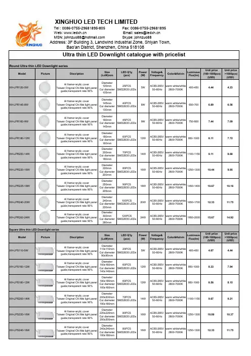
Address: 3F Building 3, Landwind Industrial Zone, Shiyan Town,ModelPictureDiscriptionSize (LxW)mmLED Q'ty (pcs)Power (W)Voltage&FrequencyColor&KelvinLuminousFlux(lm)Unit price (100-1000pcs)(USD) Unit price>1000pcs)(USD)XH-LPR120-5WAl frame+arylic coverTaiwan Original Chi Mei light panelguide,transparent rate 90%Diameter120mm Cut diameter 105mm 25PCSSMD2835 LEDs5WAC85-265V 50-60Hz warm white/white 2800-7000K400-450 4.44 4.23XH-LPR145-8W Al frame+arylic coverTaiwan Original Chi Mei light panelguide,transparent rate 90%Diameter145mm Cut diameter 130mm 40PCSSMD2835 LEDs8WAC85-265V 50-60Hz warm white/white 2800-7000K650-700 6.89 6.56XH-LPR160-9W Al frame+arylic coverTaiwan Original Chi Mei light panelguide,transparent rate 90%Diameter160mm Cut diameter 145mm 45PCSSMD2835 LEDs9WAC85-265V 50-60Hz warm white/white 2800-7000K750-8007.447.09XH-LPR180-12W Al frame+arylic coverTaiwan Original Chi Mei light panelguide,transparent rate 90%Diameter180mm Cut diameter 160mm 60PCSSMD2835 LEDs12WAC85-265V 50-60Hz warm white/white2800-7000K950-10008.117.72XH-LPR200-14W Al frame+arylic coverTaiwan Original Chi Mei light panelguide,transparent rate 90%Diameter200mm Cut diameter 180mm 70PCSSMD2835 LEDs14WAC85-265V 50-60Hz warm white/white2800-7000K1100-11509.118.68XH-LPR220-16W Al frame+arylic coverTaiwan Original Chi Mei light panelguide,transparent rate 90%Diameter220mm Cut diameter 200mm 80PCSSMD2835 LEDs16WAC85-265V 50-60Hz warm white/white2800-7000K1250-130010.449.95XH-LPR225-18W Al frame+arylic coverTaiwan Original Chi Mei light panelguide,transparent rate 90%Diameter250mm Cut diameter 205mm 90PCSSMD2835 LEDs18WAC85-265V 50-60Hz warm white/white2800-7000K1450-140010.6710.16XH-LPR240-20W Al frame+arylic coverTaiwan Original Chi Mei light panelguide,transparent rate 90%Diameter240mm Cut diameter 220mm 100PCSSMD2835 LEDs20WAC85-265V 50-60Hz warm white/white2800-7000K1650-170012.3311.75XH-LPR300-24W Al frame+arylic coverTaiwan Original Chi Mei light panelguide,transparent rate 90%Diameter300mm Cut diameter 280mm120PCSSMD2835 LEDs24WAC85-265V 50-60Hz warm white/white2800-7000K1950-200015.6714.92ModelPictureDiscriptionSize(LxW)mmLED Q'ty (pcs)Power (W)Voltage&FrequencyColor&KelvinLuminousFlux(lm)Unit price (100-1000pcs)(USD) Unit price>1000pcs)(USD)XH-LPS110-5WAl frame+arylic coverTaiwan Original Chi Mei light panelguide,transparent rate 90%Diameter110x110mm Cut diameter 90x90mm 20PCSSMD2835 LEDs5WAC85-265V 50-60Hz warm white/white 2800-7000K400-450 4.67 4.44XH-LPS160-12W Al frame+arylic coverTaiwan Original Chi Mei light panelguide,transparent rate 90%Diameter160x160mm Cut diameter 140x140mm 60PCSSMD2835 LEDs12WAC85-265V 50-60Hz warm white/white2800-7000K950-10008.337.94XH-LPS180-12W Al frame+arylic coverTaiwan Original Chi Mei light panelguide,transparent rate 90%Diameter180x180mm Cut diameter 160x160mm 60PCSSMD2835 LEDs12WAC85-265V 50-60Hz warm white/white2800-7000K950-10008.568.15XH-LPS200-14W Al frame+arylic coverTaiwan Original Chi Mei light panelguide,transparent rate 90%Diameter200x200mm Cut diameter 180x180mm 72PCSSMD2835 LEDs14WAC85-265V 50-60Hz warm white/white2800-7000K1100-11509.679.21XH-LPS220-16W Al frame+arylic coverTaiwan Original Chi Mei light panelguide,transparent rate 90%Diameter220x220mm Cut diameter 200x200mm 80PCSSMD2835 LEDs16WAC85-265V 50-60Hz warm white/white2800-7000K1250-130010.8910.37XH-LPS240-16W Al frame+arylic coverTaiwan Original Chi Mei light panelguide,transparent rate 90%Diameter240x240mm Cut diameter 180x180mm80PCSSMD2835 LEDs16WAC85-265V 50-60Hz warm white/white2800-7000K1250-130012.3311.75Square Ultra thin LED Downlight seriesRound Ultra thin LED Downlight seriesXINGHUO LED TECH LIMITEDTel : 0086-0755-********-805 Fax: 0086-0755-********Web:Email:**************MSN:**************************:johnzuo88Bao'an District, Shenzhen, China 518108Ultra thin LED Downlight catalogue with pricelistXH-LPS300-20WAl frame+arylic coverTaiwan Original Chi Mei light panelguide,transparent rate 90%Diameter300x300mmCut diameter280x280mm100PCSSMD2835 LEDs20WAC85-265V50-60Hzwarm white/white2800-7000K1650-170015.6714.92Note: 1.LED light source:LumenMax SMD2835 LEDs, 20-22lm/pc LEDs CRI>802.Warranty: 3years3. Price Term: EXW Shenzhen5.Lead time: 3-5 working days for samples, 12-15days for large quantity6.Validity: 30days, the final price should be confirmed with Xinghuo LED7.The MOQ is 100pcs ( No requirements for new customers)Company Name:Account No.:Bank Code: SWIFT Code: Bank address: 004HSBCHKHHHKHHSBC, No. 1 Queen’s Road Central, Central, Hong Kong4. Certification: CE, ROHS, Erp approvedBy T/T payment in advance, kindly write the company name correctly.XINGHUO LED TECH LIMITED561-718396-838。
DATA SHEETIntroduction Performance Characteristics Mechanical Dimensions Characteristic Curves ReliabilityPacking Specification PrecautionP 2P 3P 5P 6P 9P 10P 11 CITILED COB SeriesStandard Type.Ra70 Min., Ra80 Min. Model CLU04Q-1212E11. Introduction1-1. Product Description1-2. Features・Mechanical Dimensions :28 × 28 × 1.4 (mm)・Package Structure :Aluminum Base Chip on Board ・Reference Assembly :M3 screw, Connector ・CRI (Ra):70 Min., 80 Min.・Nominal CCT :3,000K, 4,000K, 5,000K ( CRI(Ra) 70Min. )2,700K, 3,000K, 3,500K, 4,000K, 5,000K, 5,700K, 6,500K ( CRI(Ra) 80Min. )・Chromaticity Range:3-step Ellipse, the center refers to ANSI C78.377:2017. ( CRI(Ra) 70Min. )2-step Ellipse, the center refers to ANSI C78.377:2017. ( CRI(Ra) 80Min. )・Thermal Resistance :0.32C/W ・Maximum drive current :2760mA ・UL recognized component (E358566)・RoHS compliant・Better die arrangement for optics・Wide range of luminous flux and high efficacy・Improved lumen density compared with previous version CLU04Q -1212E1-303L7X4[1][2][3][4][5][1]:[2]:[3]:[4]:[5]:Nominal CCT CRI (Ra)Product NomenclatureCLU04Q 12123000K 70 Min.Product shape Die count in series Die count in parallel CITIZEN ELECTRONICS is the first COB manufacturer.With many years of knowledge, experience, and advanced packaging technology, we continue to produced high quality and highly reliable products.The new COB series, Version9, while keeping the conventional product lineup and package sizes, achieves both high color quality (2 Step ellipse) and higher driving capability.In addition, efficacy and reliability are improved by selecting superior materials and optimizing production processes.Our highly reliable and efficient COB light source contributes to the realization of a circular economy through energy saving and reduction of carbon emissions.2. Performance Characteristics2-1. Electro Optical Characteristics2-2. Absolute Maximum RatingsSymbol RatingPi 116.5*1If 2760*1Ir 1Top -40 ~ +100Tst -40 ~ +100Tc 120*2Tj140*3*2. Refer to 3. Outline drawing for Tc measurement point.*3. Junction temperature calculation formula : Tj = Tc + Rj-c × PiParameterInput Power (W)Forward Current (mA)Reverse Current (mA)Storage Temperature (C)Case Temperature (C)Junction Temperature (C)Operating Temperature (C)*1. Input power and forward current are the values when the LED is used within the range of the derating curve in this data sheet.( Tj=85C )Ra R9Tc25C*Min.Min.Min.Typ.Typ.Typ.Min.Typ.Max.CLU04Q-1212E1-303L7X43000K 70-5,6566,4286,9251761,08031.433.836.20.32CLU04Q-1212E1-403L7X44000K 70-5,6896,4656,9651771,08031.433.836.20.32CLU04Q-1212E1-503L7X45000K 70-5,7106,4896,9911781,08031.433.836.20.32CLU04Q-1212E1-272M2X22700K 8004,9915,6736,1111551,08031.433.836.20.32CLU04Q-1212E1-302M2X23000K 8005,1845,8926,3471611,08031.433.836.20.32CLU04Q-1212E1-352M2X23500K 8005,3036,0276,4931651,08031.433.836.20.32CLU04Q-1212E1-402M2X24000K 8005,4256,1666,6421691,08031.433.836.20.32CLU04Q-1212E1-502M2X25000K 8005,4096,1476,6231681,08031.433.836.20.32CLU04Q-1212E1-572M2X25700K 8005,3546,0856,5561671,08031.433.836.20.32CLU04Q-1212E1-652M2X26500K805,3046,0276,4941651,08031.433.836.20.32Notes :1. Citizen Electronics maintains a tolerance of ± 10% on luminous flux measurements.2. Citizen Electronics maintains a tolerance of ± 3% on forward voltage measurements.3. Citizen Electronics maintains a tolerance of ± 2 on Ra measurements. * : Values of Luminous flux at Tc=25C are provided as reference only.Product codeForward Current( mA )Thermal Resistance Rj-c ( C/W )CRI Nominal CCTLuminous flux( lm )Efficacy ( lm/W )Forward Voltage( V )Tj85C2,700K ( 0.4578, 0.4101)3,000K( 0.4339, 0.4033)3,500K ( 0.4078, 0.3930)4,000K ( 0.3818, 0.3797)5,000K ( 0.3446, 0.3551)5,700K ( 0.3287, 0.3425)6,500K( 0.3123, 0.3283)3-step Ellipse.2-step Ellipse.Color RegionNominal CCT Center Point ( x, y )---0.003540.00236-0.00507-0.001983-step 2-step 0.0083452.970.00634-0.00278 ( Rated current, Tj=85C )53.170.005560.004080.002720.00516-0.0027457.28Oval parameterMajor Axisa Minor Axisb E llipse Rotation Angleθ3-step 2-step * Color region stay within 3-step / 2-step ellipse from the chromaticity center.* The chromaticity center refers to ANSI C78.377:2017.* θ is the angle between the major axis of the ellipse and the x-axis, and a and b are the major and minor semi-axes of an ellipse.54.0059.6258.3859.460.009390.006260.004020.002680.00446-0.001900.008220.005482-3. Chromaticity CharacteristicsNote : Citizen Electronics maintains chromaticity ( x, y ) +/-0.0050.300.350.400.450.300.350.400.450.50yxx-y chart CIE19314,000K3,000KBlack Body Locus2,700K3,500K5,000K5,700K6,500K2-step 3-step3. Mechanical DimensionsUnit : mmTolerances unless otherwise specified : +/-0.3・Internal Circuit12 S 12 P Protection deviceLED deviceCathodeAnodeMarking 1 : Serial No.Marking 2 : Code No.CRI CCTDie count in parallel Die count in seriesCLU0xQ seriesMarking 3 : Data MatrixAN 12 12 ** ** *4. Characteristic Curves4-1. Forward Current Characteristics / Temperature CharacteristicsForward Current vs. Forward VoltageForward Current vs. Relative Luminous FluxTc=25CTc=25CCase Temperature vs. Forward VoltageCase Temperature vs. Relative Luminous FluxIf=1080mAIf=1080mA30.032.034.036.038.040.00100020003000V f [V ]If [mA]0%50%100%150%200%250%100020003000R e l a t i v e L u m i n o u s F l u x [a .u .]If [mA]32.033.034.035.036.0255075100125V f [V ]Tc [C]0%20%40%60%80%100%120%0255075100125R e l a t i v e L u m i n o u s F l u x [a .u .]Tc [C]4-2. Optical CharacteristicsTj=85CIf=1080mASpectrum : CRI(Ra) 80 Min.0%10%20%30%40%50%60%70%80%90%100%380430480530580630680730780R a d i a t i v e I n t e n s i t yWave length [nm]6,500K5,700K 5,000K 4,000K 3,500K 3,000K2,700KTj=85CIf=1080mASpectrum : CRI(Ra) 70 Min.0%10%20%30%40%50%60%70%80%90%100%380430480530580630680730780R a d i a t i v e I n t e n s i t yWave length [nm]5,000K4,000K3,000K4-2. Optical Characteristics (continued)4-3. Derating CharacteristicsRadiation Characteristic0%20%40%60%80%100%X Y80°70°60°50°40°30°20°10°-80°-70°-60°-50°-20°-30°-40°-10°90°-90°Case Temperaturevs. Allowable Forward Current1000200030000255075100125I f [m A ]Tc [C]5. Reliability5-1. Reliability Test5-2. Failure Criteria-40 C × 30 minutes – 100 C × 30 minutes, 100 cycle85 C, 85 %RH for 500 hoursThermal Shock TestContinuous Operation Test High Temperature Storage TestLow Temperature Storage Test Moisture-proof Test If=1080mA , Tj=140C (with Al-fin) ×1000hoursTest Item100 C × 1000 hours -40 C × 1000 hours Test ConditionIf=1080mA , Ta= 25C (with Al-fin) ×1000hours ( Tc=25C )U defines the upper limit of the specified characteristics. S defines the initial value.Note : Measurement shall be taken between 2 hours and 24 hours, and the test pieces should be return to the normal ambient conditions after the completion of each test.Total Luminous FluxΦvIf=1080mA<S × 0.85Measuring Item Symbol Measuring ConditionFailure CriteriaForward Voltage Vf If=1080mA >U × 1.1Unit : mmProduct : 30 pcs/tray1. TYPEe.g. CLU04Q-1212E12. P.No. ( Customer's P/N )3. Lot No.2175015(b)(a) Last two digit of the year 21 : Year 2021(b) Production month 7 : JulyNote: October, November and December are designated X,Y and Z.(c) CE's control number 4. Quantity(a)(c)Example of indication labele.g. 6. Packing Specification6-1. PackingAn empty tray is placed on top of a 6-tier tray which contain 30 pieces each.( Smallest packing unit : 180 pieces )A label with product name, quantity and lot number is placed on the upper empty tray.Tray ( Dimensions: 310 x 210 x 12 mm / Materials: Electrically conductive PS ) CUSTOMERTYPE P.NO Lot No Q'ty: CLU***-******-******* : ****** : ******* : ***--- ( 1 ) --- ( 2 ) --- ( 3 ) --- ( 4 )7. Precaution7-1. Handling with care for this product-Both the light emitting area and white rim around the light emitting area is composed of resin materials.Please avoid the resin area from being pressed, stressed, rubbed, come into contact with sharp metal nail(e.g. edge of reflector part) because the function, performance and reliability of this product are negatively impacted.-Please be aware that this product should not come into contact with any other parts while incorporating in your lightingapparatus or your other products.-Please be aware that careful handling is required after the attachment of lead wires to prevent the application of any loadto the connections.-For more information, please refer to application note "Instruction Manual(COB LED Package)".7-2. Countermeasure against static electricity-Handling of this product needs countermeasures against static electricity because this is a semiconductor product.-Please take adequate measures to prevent any static electricity being produced such as the wearing of a wristband oranti-static gloves when handling this product.-Every manufacturing facility in regard to the product (plant, equipment, machine, carrier machine and conveyance unit)should be connected to ground and please avoid the product to be electric-charged.-ESD sensitivity of this product is over 1000V (HBM, based on JEITA ED-4701/304).-After assembling the LEDs into your final product(s), it is recommended to check whether the assembled LEDs aredamaged by static electricity (electrical leak phenomenon) or not.-It is easy to find static damaged LED dies by a light-on test with the minimum current value.7-3. Caution of product assembly-Regarding this product assembling on the heat sink, it is recommended to use M3 screw.It might be good for screw tightening on the heat sink to do temporary tightening and final tightening.In addition, please don’t press with excess stress on the product.-The condition of the product assembling on the heat sink and the control of screw tightening torque needs to be optimized according to the specification of the heat sink.-Roughness, unevenness and burr of surface negatively impact thermal bonding between the product and heat sink andincrease heat thermal resistance between them.Confidence of thermally and mechanical coupling between the product and heat sink are confirmed by checkingthe mounting surface and measuring the case temperature of the product.-In order to reduce the thermal resistance at assembly, it might be good to use TIM (Thermal Interface Material) on whole contact surface of the product.In case of using thermal grease for the TIM, it might be good to apply uniformly on the contact surface of the product.In case of using thermal sheet for the TIM, it might be good to make sure that the product is NOT strained by stress when the screws are tightened for assembly.-For more information, please refer to application note "Instruction Manual(COB LED Package)".7-4. Thermal Design-The thermal design to draw heat away from the LED junction is most critical parameter for an LED illumination system. High operating temperatures at the LED junction adversely affect the performance of LED’s light output and lifetime. Therefore the LED junction temperature should not exceed the absolute maximum rating in LED illumination system. -The LED junction temperature while operation of LED illumination system depends upon thermal resistance of internal LED package (Rj-c), outer thermal resistances of LED package, power loss and ambient temperature. Please take both of the thermal design specifications and ambient temperature conditions into consideration for the setting of driving conditions.-For more information, please refer to application note "Thermal Management", "Instruction Manual(COB LED Package)".7-5. Driving Current-A constant current is recommended as an applying driving current to this product.In the case of constant voltage driving, please connect current-limiting resistor to each products in series and control the driving current to keep under the absolute maximum rating forward current value.-Electrical transient might apply excess voltage, excess current and reverse voltage to the product(s).They also affect negative impact on the product(s) therefore please make sure that no excess voltage, no excess current and no reverse voltage is applied to the product(s) when the LED driver is turn-on and/or turn-off.-For more information, please refer to application note "Driving", "Instruction Manual(COB LED Package)".7-6. Lighting at a minimum current value-A minimum current value of lighting of all dice is 15mA.When a minimum current is applied, LED dice may look different in their brightness due to the individual difference of the LED element, and it is not a failed product.7-7. Electrical Safety-This product is designed and produced according to IEC 62031:2008(IEC 62031:2008 LED modules for general lighting. Safety specification)-Dielectric voltage withstand test has been conducted on this product to see any failure after applyingvoltage between active pads and aluminum section of the product, and to pass at least 500V.-Considering conformity assessment for IEC62031:2008, almost all items of the specification depend uponyour final product of LED illumination system.Therefore, please confirm with your final product for electrical safety of your product.As well, the products comply with the criteria of IEC62031:2008 as single LED package.- A minimum current value of lighting of all dice is 60 mA. When a minimum current is applied, LED dice may look different in their brightness due tothe individual difference of the LED element, and it is not a failed product.7-8. Recommended soldering Condition (This product is not adaptable to reflow process.) -For manual solderingPlease use lead-free soldering.Soldering shall be implemented using a soldering bit at a temperature lower than 350C, and shall befinished within 3.5 seconds for one land.No external force shall be applied to resin part while soldering is implemented.Next process of soldering should be carried out after the product has return to ambient temperature.Contacts number of soldering bit should be within twice for each terminal.* Citizen Electronics cannot guarantee if usage exceeds these recommended conditions.Please use it after sufficient verification is carried out on your own risk if absolutely necessary.-For more information, please refer to application note "Instruction Manual(COB LED Package)".7-9. Eye Safety-The International Electrical Commission (IEC) published in 2006 IEC 62471”2006 Photobiological safety of lamps and lamp systems ” which includes LEDs within its scope.When sorting single LEDs according to IEC 62471, almost all white LEDs can be classifiedas belonging to either Exempt Group (no hazard) or Risk Group 1 (low risk).-However, Optical characteristics of LEDs such as radiant flux, spectrum and light distribution are factorsthat affect the risk group determination of the LED, and especially a high-power LED, that emits lightcontaining blue wavelengths,might have properties equivalent to those of Risk Group 2 (moderate risk).-Great care should be taken when directly viewing an LED that is driven at high current, has multipleuses as a module or when focusing the light with optical instruments, as these actions might greatlyincrease the hazard to your eyes.-It is recommended to regard the evaluation of stand-alone LED packages as a referenceand to evaluate your final product.7-10. This product is not designed for usage under the following conditions.If the product might be used under the following conditions, you shall evaluate its effect and appropriate them. In places where the product might:-directly and indirectly get wet due to rain and/or at place with the fear.-be damage by seawater and/or at place with the fear-be exposed to corrosive gas (such as Cl2, H2S, NH3, SOx, NOx and so on) and/or at place with the fear.-be exposed to dust, fluid or oil and/or at place with the fear.Precautions with regard to product use(1) This document is provided for reference purposes only so that CITIZEN ELECTRONICS' products are used as intended. CITIZEN ELECTRONICS neither makes warranties or representations with respect to the accuracy or completeness of the information contained in this document nor grants any license to any intellectual property rights or any other rights of CITIZEN ELECTRONICS or any third party with respect to the information in this document. Before purchasing or using any CITIZEN ELECTRONICS' products listed in this document, please confirm the latest product information with a CITIZEN ELECTRONICS‘s sales office, and formal specifications must be exchanged and signed by both parties prior to mass production.(2) All information included in this document such as product data, diagrams, charts, is current as of the date this document is issued.Such information, however, is subject to change without any prior notice.(3) CITIZEN ELECTRONICS has used reasonable care in compiling the information included in this document, but CITIZEN ELECTRONICS assumes no liability whatsoever for any damages incurred as a result of errors or omissions in the information included in this document.(4) Absent a written signed agreement, except as provided in the relevant terms and conditions of sale for product, and to the maximum extent allowable by law, CITIZEN ELECTRONICS assumes no liability whatsoever, including without limitation, indirect, consequential, special, or incidental damages or loss, including without limitation, loss of profits, loss of opportunities, business interruption and loss of data, and disclaims any and all express or implied warranties and conditions related to sale, use of product, or information, including warranties or conditions of merchantability, fitness for a particular purpose, accuracy of information, or no infringement.(5) Though CITIZEN ELECTRONICS works continually to improve products' quality and reliability, products can malfunction or fail. Customers are responsible for complying with safety standards and for providing adequate designs and safeguards to minimize risk and avoid situations in which a malfunction or failure of a product could cause loss of human life, bodily injury or damage to property, including data loss or corruption. In addition, customers are also responsible for determining the appropriateness of use of any information contained in this document such as application cases not only with evaluating by their own but also by the entire system. CITIZEN ELECTRONICS assumes no liability for customers' product design or applications.(6) The LEDs described in this brochure are intended to be used for ordinary electronic equipment (such as office equipment, communications equipment, measurement instruments and household appliances). Consult Citizen Electronics’s sales staff in advance for information on the applications in which exceptional quality and reliability are required, particularly when the failure or malfunction of the LEDs may directly jeopardize life or health ( such as for airplane, aerospace, submersible repeaters, nuclear reactor control system, automobiles, traffic control equipment, life support system and safety devices ) . This LED does not comply with ISO/TS 16949 (IATF16949) and is not intended for automotive applications.(7) The customer shall not reserve engineer by disassembling or analysis of the LEDs without having prior written consent from Citizen Electronics. When defective LEDs are found, the customer shall inform Citizen Electronics before disassembling or analysis.(8) When exporting our products, please ensure conformance with applicable laws and regulations and take appropriate actions such as obtaining an export license.(9) Please do not use or supply our products for any weapons of mass destruction (WMD) or for any other military purposes.(10) Please contact CITIZEN ELECTRONICS' sales office if you have any questions regarding the information contained in this document, or if you have any other inquiries.is a trademark or a registered trademark of CITIZEN ELECTRONICS CO., LTD. JAPAN. **********************.co.jp。

and reliability.如产品需要用在有特殊质量要求及可靠性要求的地方,请提前咨询瑞丰的销售人员以取得相关信息。
disassemble and analyzein written form.在取得瑞丰的同意前,客户不应该对产品进行拆解分析,如发现失效产品,请直接书面通知瑞丰。
Features 特征Extremelywide viewing angle.发光角度大Suitable for all SMT assembly and solder process.适用于所有的SMT 组装和焊接工艺 Moisture sensitivity level:Level 3.防潮等级Level 3 Package:4000pcs/reel.包装每卷4000pcs RoHS compliant.满足RoHS 要求Description 描述The Colour LED which was fabricated by using a green chip 该产品为绿光LED ,是由绿光芯片封装形成Applications 应用Optical indicator.光学指示Switch and Symbol,Display.开关和标识、显示器等 General use.其他应用RF-GNS150TS-CFPackage Dimension外观尺寸NOTES:1.All dimensions units are millimeters.(所有尺寸标注单位为毫米)2.All dimensions tolerances are 0.2mm unless otherwise noted.(除特别标注外,所有尺寸公差为±0.2毫米)Electrical/Optical Characteristics at Ts=25°C电性与光学特性Note:备注Vr=5V For test conditions.Vr=5v为测试分选条件。
普诚科技LED照明驱动IC产品手册_REV8:0 普诚科技LED照明驱动IC产品手册_REV8:0一、产品概述1.1 产品名称及型号1.2 产品特性1.3 适用范围1.4 产品架构二、产品参数2.1 电气参数2.1.1 输入参数2.1.2 输出参数2.1.3 工作温度范围2.2 功能参数2.2.1 PWM控制2.2.2 打灯模式2.2.3 过温保护2.2.4 短路保护 2.2.5 开路保护 2.2.6 过压保护2.2.7 低压保护三、产品接口3.1 输入接口3.2 输出接口3.3 配置接口3.4 通信接口四、产品使用说明4.1 安装方式4.2 驱动连接方式 4.3 驱动设置参数4.4 驱动故障处理五、产品应用实例5.1 建筑照明5.2 商业照明5.3 家居照明5.4 景观照明六、故障排除6.1 常见问题及解决方法6.2 维修与保养附件:1、产品尺寸图2、电路原理图3、产品连接示意图法律名词及注释:1、LED:Light Emitting Diode的缩写,即发光二极管,是一种固体半导体器件,能将电能转化为可见光。
2、PWM:Pulse Width Modulation的缩写,即脉宽调制,是一种通过改变脉冲信号的占空比来控制电压或电流的方法。
3、过温保护:当芯片温度超过一定阈值时,系统自动采取保护措施,以防止芯片过热损坏。
4、短路保护:当输出回路短路时,系统自动切断输出,以保护LED和驱动芯片。
5、开路保护:当输出回路断路时,系统自动切断输出,以保护LED和驱动芯片。
6、过压保护:当输入电压超过一定阈值时,系统自动采取保护措施,以防止芯片过压损坏。
7、低压保护:当输入电压低于一定阈值时,系统自动切断输出,以保护LED和驱动芯片。
LED灯产品说明书
一、产品概述
LED灯是一种高效、环保、节能的照明产品,采用最新的LED技术,具有长寿命、低能耗、高亮度等优点。
本产品适用于家庭、办公室、商场、酒店等场所的照明需求。
二、产品特点
1.长寿命:LED灯的使用寿命长达5万小时以上,比传统白炽灯和荧光灯更耐用。
2.低能耗:LED灯的能耗仅为传统白炽灯的1/10,具有极高的节能效果。
3.高亮度:LED灯的亮度比传统白炽灯更高,能够提供更明亮的照明效果。
4.环保:LED灯不含有害物质,对环境和人体健康无害。
5.易于安装:LED灯采用标准接口,可以方便地安装到各种灯具上。
三、使用方法
1.安装:请按照说明书中的步骤正确安装LED灯,确保电源连接稳定。
2.使用:打开电源开关,LED灯即可正常工作。
可以根据需要调节亮度。
3.维护:定期清理灯具表面灰尘,保持灯具清洁。
如遇故障,请联系专业维修人员。
四、注意事项
1.请勿在潮湿环境下使用LED灯。
2.请勿在高温环境下长时间使用LED灯。
3.请勿在电源不稳定的环境下使用LED灯。
4.请勿拆卸或自行维修LED灯。
五、售后服务
本产品自购买之日起享受一年质保服务。
如有质量问题或使用不当导致的损坏,可凭购买凭证免费维修或更换。
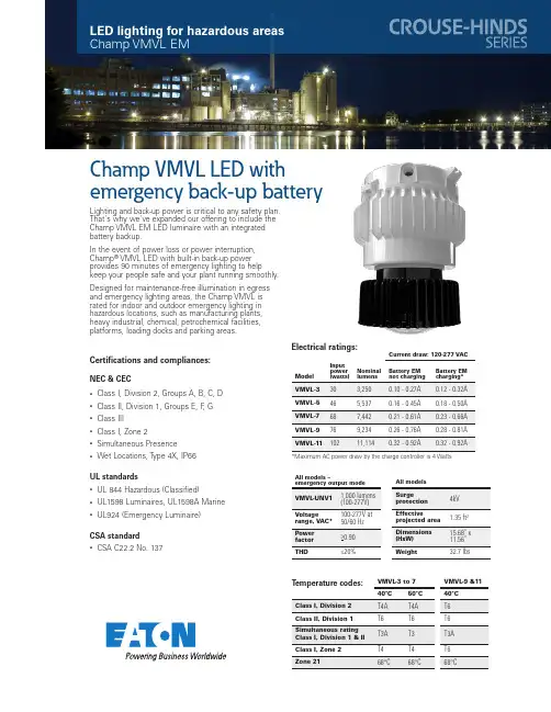
LED lighting for hazardous areas Champ VMVL EMChamp VMVL LED with emergency back-up batteryCertifications and compliances:NEC & CEC• Class I, Division 2, Groups A, B, C, D • Class II, Division 1, Groups E, F , G • Class III • Class I, Zone 2• Simultaneous Presence •Wet Locations, Type 4X, IP66UL standards• UL 844 Hazardous (Classified)• UL1598 Luminaires, UL1598A Marine •UL924 (Emergency Luminaire)CSA standard•CSA C22.2 No. 137Lighting and back-up power is critical to any safety plan. That's why we've expanded our offering to include the Champ VMVL EM LED luminaire with an integrated battery backup.In the event of power loss or power interruption, Champ ® VMVL LED with built-in back-up powerprovides 90 minutes of emergency lighting to help keep your people safe and your plant running smoothly.Designed for maintenance-free illumination in egress and emergency lighting areas, the Champ VMVL is rated for indoor and outdoor emergency lighting in hazardous locations, such as manufacturing plants, heavy industrial, chemical, petrochemical facilities, platforms, loading docks and parking areas.VMVL -3 to 7VMVL -9 &11T emperature codes:All models –THDCurrent draw: 120-277 VAC Input power NominalBattery EM Battery EMElectrical ratings:*Maximum AC power draw by the charge controller is 4 Watts WeightEaton is a registered trademark.All other trademarks are property of their respective owners.Eaton’s Crouse-Hinds 1201 Wolf Street Syracuse, NY © 2022 EatonAll Rights Reserved Printed in USAPublication No. 5461-0322March 2022Ordering information20A20mm pendant3C1” ceiling25TW25mm wallAccessories(ordered separately)P3002Wire guardREPLACEMENT KITReplacement EM driver*Consult factory for lead time*Available with ceiling mounted modules only.Part number example: VMVL -3-W-2A-G-UNV1-EM1VMVL Champ VMVL, 3,000 lumens, 4000K warm white, ¾" pendant mount, Type V optics, wire guard, 100-277 VAC driver, emergency driver system, clear glass lens/ChampDimensions:。
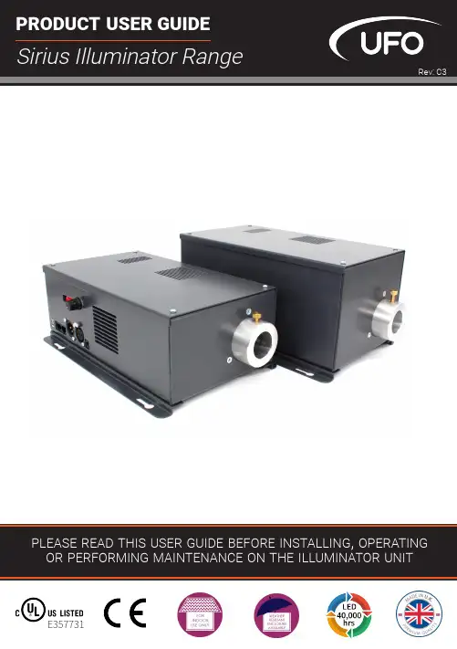
PLEASE READTHIS USER GUIDE BEFORE INSTALLING, OPERATING OR PERFORMING MAINTENANCE ON THE ILLUMINATOR UNIT PRODUCT USER GUIDESirius Illuminator RangeE357731Rev: C3Thank you for purchasing this UFO illuminator/luminaire.To ensure that the illuminator is set up optimally and gives a long service life, please read this user guide before installing, operating or performing any maintenance on the unit.Please keep this User Guide for future reference. This User Guide is laid out in three sectionsInstallation -details on how to connect your luminaireOperation - details how to programme and set up your luminaireMaintenance - maintenance log, troubleshooting guide, technical specificationMODELS COVERED BY THIS USER GUIDEUFOSIRCW UFOSIRCW-C UFOCIRCW-T UFOSIRCW-Cs UFOSIRCW-TsUFOSIRSW UFOSIRSW-C UFOSIRSW-T UFOSIRSW-Cs UFOSIRSW-TsUFOSIRNW UFOSIRNW-C UFOSIRNW-T UFOSIRNW-Cs UFOSIRNW-TsUFOSIRWW UFOSIRWW-C UFOSIRWW-T UFOSIRWW-Cs UFOSIRWW-TsUFOSIRGW UFOSIRGW-C UFOSIRGW-T UFOSIRGW-Cs UFOSIRGW-TsUFOSIRGW27UFOSIRGW27-C UFOSIRGW27-T UFOSIRGW27-Cs UFOSIRGW27-Ts IMPORTANTThis product must be installed in accordance with the applicable installation code, by a person familiar with the construction and operation of the product, and the hazards involved.These illuminators are not mains dimmable.The LED array and heatsink in this illuminator can be replaced when it reaches end of life. Contact UFO for details.Type Y Attachment: If the external flexible cable or cord of this luminaire or associatedPSU/driver is damaged, it shall be exclusively replaced by the manufacturer or his service agent or a similar qualified person to avoid a hazard.Location: Do not locate this illuminator closer than 200mm from any flammable surface.Clearance / Ventilation: It is imperative that a gap of 200mm is left around the unit. This is to allow air to circulate and prevent overheating. The location must have free ventilation and must not have an ambient temperature higher than that specified for the luminaire.Mounting: This luminaire comes with an integral mounting plate for securing the unit to a vertical or horizontal surface. Refer to the instruction sheet supplied with the plate. Warning: Never look directly at the luminaire through the fiber port of the illuminator. Warning: The luminaire should be positioned so that prolonged staring into theluminaire at a distance closer than 2.7 metres is not expected.23UFO LIGHTING1. Manual dimming - local and remote2. No sensor, manual decorative wheel control (wheel speeds 0.5rpm, 1.2rpm, 2.4rpm, 4rpm, 7.5rpm and stop), stop on random color3. Sensor, manual decorative wheel control (wheel speeds 1.6rpm, 2.6rpm, 3.75rpm, 5.5rpm and stop), stop on 1 color4. DMX dimming5. No sensor - DMX decorative wheel control, adjustable speed from stop up to 7.5rpm + LED and fan on/off6. Sensor - DMX decorative wheel control, snap colors andadjustable speed from stop up to 7.5rpm + LED and fan on/off 7. No sensor - 0-10v decorative wheel control, adjustable speed from stop up to 7.5rpm - channel 1 (receiving)8. Sensor - 0-10v decorative wheel control, snap colors andadjustable speed from stop up to 7.5rpm - channel 1 (receiving)9. 0-10V dimming – channel 2 (receiving) - two versions, standard and emergency lightThe Sirius is a 90W white light LED illuminator with optional decorative wheel capability. The Sirius LED illuminator driver PCB has all the control functionality fitted as standard. The following control functionality and configurations are available.MODEL TYPESThe Sirius LED illuminator incorporates a range of LED arrays focussed through a series of static lenses to provide optimum display and illumination within the following optical range.MODEL TYPES [CONT ]SIRIUS RANGE USER GUIDE4CONNECTIONS AND CONTROLS OVERVIEW0-10VDIMMING DMX 24V DC INPUT MANUAL DIMMINGMANUALDMX ADDRESS AND CONTROLMOUNTING FEETThe illuminator is supplied with non-slip rubber feet pre-fitted the base of the unit. Alsoin the box there are 2 x user fixable mounting brackets which allow for the illuminator tobe securely mounted to a wall or other surface if necessary.To fit these feet, remove the 4 rubber feet from the base of the unit and retain the screws.The wall mounting brackets are supplied as a pair - one left and one right hand. Positionthe brackets over the holes that have been left empty by the rubber feet and fix in placewith the removed screws.The illuminator can now be fixed to the mounting surface.5SIRIUS RANGE USER GUIDE6CONNECTION - FOR LOCAL MANUAL OPERATIONThere are 2 connections required – the fiber port and the mains supply cable. The fiber port should be connected first. Connect and secure the fiber optic connector into the collar and secure using the M5 locking screw.Connect the PSU to the DC input jack socket on the illuminator, and connect the IEC plug to the PSU. Plug the mains plug into the electrical supply socket. Switch on power. The LED Indicator on the PSU will illuminate and the illuminator is ready for use. If no light is produced consult the TROUBLESHOOTING section of this user guide.CONNECTION - FOR LOCAL MANUAL OPERATION There are 3 connections required – the fiber port, the remote dimmer cable and the mains supply cable. The fiber port should beconnected first. Connect and secure the fiber optic connector into the collar and secure using the M5 locking screw. Connect the RJ45 connector on the end of the remote dimmer cable as detailed below into the right hand RJ45 socket (0-10V dimming) on the side of the illuminator.Connect the PSU to the DC input jack socket on the illuminator, and connect the IEC plug to the PSU. Plug the mains plug into the electrical supply socket. Switch on power. The LEDIndicator on the PSU will illuminate and the illu-minator is ready for use. If no light isproduced consult the TROUBLESHOOTINGsection of this user guide.7There are 3 connections required – the fiber port, the mains supply cable and the DMX cables. The fiber port should be connected first. Connect and secure the fiber optic connector into the aluminium collar and secure using the M5 locking screw.Connect the PSU to the DC input jack socket on the illuminator, and connect the IEC plug to the PSU. Plug the mains plug into the electrical supply socket. Switch on power. The LED Indicator on the PSU will illuminate and the illuminator is ready for use. If no light is produced consult the TROUBLESHOOTING section of this user guide.Connect to the 3 pin XLR sockets on the side panel as detailed below using an approved DMX cable.Only approved DMX cables should be used.Always “daisy chain” a DMX universe. Never use a T joint in a DMX universe unless using an approved interface.It is always recommended that the last illuminator output in the DMX universe or cable run be terminated with a 120 ohm resistor across DMX+ and DMX-.SIRIUS RANGE USER GUIDE8There are 3 connections required – the fiber port, the mains supply cable and the 0-10V cable. The fiber port should be connected first. Connect and secure the fiber optic connector into the aluminium collar and secure using the M5 locking screw.Connect the PSU to the DC input jack socket on the illuminator, and connect the IEC plug to the PSU. Plug the mains plug into the electrical supply socket. Switch on power. The LED Indicator on the PSU will illuminate and the illuminator is ready for use. If no light is produced consult the TROUBLESHOOTING section of this user guide.Connect the 0-10V RJ45 as detailed below using CAT5 cable.Note : for emergency light functionality, the mains supply for the illuminator must bemaintained so that failure of the mains supply to the 0-10V controller will result in the illumina-0-10V RJ45 Connections:-VE RJ45 Brown/White (Pin 7) +VE RJ45 Blue/White (Pin 5)POWER SUPPLY REQUIREMENTSThe LED illuminator is powered from a 24V DC PSU/Constant Voltage SELV LED driver.The driver caters for UK/European/other mains supplies using the relevant power cord supplied.9UFO LIGHTINGLOCAL WHITE LIGHT DIMMINGAll Sirius models in the range can be manually controlled as detailed in the following sections.Note: For all manual operation modes, dip switch 10 must be set to on.During normal manual white light operation, the illuminator can be dimmed from 0 to 100% using the manual dimming control on the side panel.EMERGENCY WHITE LIGHT DIMMINGDuring normal manual white light operation the emergency light configured illuminator can be dimmed from maximum light at 0%, to no light at 10% then again up to maximum light at 100% using the manual dimming control on the side panel.DECORATIVE COLOR OR TWINKLE WHEEL CONTROL - WITHOUT SENSORDuring normal manual decorative operation the illuminator can be dimmed from 0 to 100% using the manual dimming control and the motor can be controlled from stop to 5 speeds (see table below) using the push button manual motor control on the side panel.Note: When manually selecting stop (switch position 6) the decorative wheel will stop instantly on a random color (color wheel) or a random section of the twinkle wheelREMOTE WHITE LIGHT DIMMINGDuring remote manual white light operation, the illuminator can be dimmed from 0 to 100% using the remote dimming control.Note : For remote manual dimming operation, dip switch 10 on the illuminator must be set to on and the local manual dimming control on the side of the illuminator must be turned to mini-mum (fully counter clockwise)SIRIUS RANGE USER GUIDE10DECORATIVE TWINKLE WHEEL CONTROL - WITH SENSORDuring normal manual decorative operation the illuminator can be dimmed from 0 to 100% using the manual dimming control and the motor can be controlled with stop + 4 speeds ranging from very slow to fast using the push button manual motor control on the side panel.Note: For this configuration the twinkle wheel is supplied with a cut out segment. The wheel in motion will give an uninterrupted twinkle by rotating backwards and forwards either side of the segment. When stop is selected the wheel will come to rest at the segment giving unobstructed white light output.DECORATIVE COLOR WHEEL CONTROL - WITH SENSORDuring normal manual decorative operation the illuminator can be dimmed from 0 to 100% using the manual dimming control and the motor can be controlled from stop to 4 speeds (see table below) using the push button manual motor control on the side panel.Note: When manually selecting stop (switch position 5) the decorative wheel will automatically return to color 1 (normally white)DMX OPERATIONEach Sirius occupies 3 DMX channels• Channel 1 dimming• Channel 2 decorative wheel control • Channel 3 LED and fan ON/OFF controlDecorative wheel DMX functions are different depending on decorative model. More details on individual DMX channels and values are provided in the following DMX tablesNote : For ALL DMX operations, DIP switch 10 on the illuminator must be set to off, the correct DMX address must be set (switches 1-9) and the XLR plug(s) must be plugged into the XLR sockets on the side panel.11LIGHTINGSETTING THE DMX ADDRESSBecause the Sirius occupies 3 DMX channels, when setting addresses on multiple illuminators the addresses must be selected to give 3 channel separation. For example, if the first address is 009, the next address must be at least 012, the next address must be at least 015 and so on. Any illuminators with the same address will operate identically under DMX control.The DMX address is set manually using the DIP switch on the side panel of the Sirius. Each DIP switch number (1 to 9) represents a binary number which when added together make up the DMX address as shown in the table below.WHITE LIGHT DIMMINGThe illuminator can be dimmed on DMX channel 1 and controlled on DMX channel 3 as detailed in Table A. DMX Channel 2 is redundant.Alternatively use the online calculator from link below: /calc.aspSIRIUS RANGE USER GUIDE12The Illuminator can be controlled as detailed in Table ASIRIUS DMX CHANNELS - TABLE AEach Sirius occupies 3 DMX channels as detailed below.DECORATIVE COLOR OR TWINKLE WHEEL CONTROL - WITH SENSORFor this configuration of a decorative wheel with sensor:• The Twinkle wheel has a cut-out segment. The wheel in motion will give an uninterrupted twinkle by rotating backwards and forwards either side of the cut-out segment. When stopped the wheel will return to the cut-out segment and display unobstructed white light • The color wheel when stopped will return to color wheel segment 1 (normally white) The Illuminator can be controlled as detailed in Table B for Color Wheel with sensor and Table C for Twinkle Wheel with sensorDECORATIVE COLOR OR TWINKLE WHEEL CONTROL - NO SENSORFor this configuration of a decorative wheel without sensor:• The Twinkle wheel is solid with no cut out segment. The wheel in motion will give a continu-ous twinkle effect. When stopped the wheel will remain in front of the LED array giving an ob-structed white light output• The color wheel when stopped will display the color where it stoppedThe illuminator decorative wheel can be controlled on DMX channel 2 as shown in table A.SIRIUS DMX CHANNELS - TABLE BEach Sirius occupies 3 DMX channels as detailed below.13 LIGHTINGSIRIUS DMX CHANNELS - TABLE CEach Sirius occupies 3 DMX channels as detailed below:14SIRIUS RANGE USER GUIDE15UFO LIGHTINGSTANDARD WHITE LIGHT DIMMINGOnce the Sirius illuminator has been set up and connected as detailed above the illuminator can be dimmed from 0 (0 Volts DC) to 100% (10V DC) with a receiving 0-10V signal.EMERGENCY WHITE LIGHT DIMMINGOnce the Sirius illuminator has been set up and connected as detailed above the illuminator can be dimmed with a receiving 0-10V signal as detailed in the table below:Note: In this configuration when the mains supply to the 0-10V controller fails, the illuminator will illuminate fully as an emergency light.For ALL 0-10V operation control DIP switch 10 on the Sirius illuminator side panel must be set to ON and in addition:• For 0-10V dimming the Manual Dimming Control on the Sirius illuminator side panel must be set to minimum (fully counter clockwise) and the RJ45 plug must be plugged into the right hand (0-10V dimming) RJ45 socket on the side panel.• For 0-10V decorative wheel control the Manual Motor Control on the Sirius illuminator side panel must be set to STOP and the RJ45 plug must be plugged into the left hand (0-10V motor.SIRIUS RANGE USER GUIDE16DECORATIVE COLOR OR TWINKLE WHEEL CONTROL - WITH SENSOROnce the Sirius illuminator has been set up and connected as detailed above the illuminator decorative wheel can be controlled with a receiving 0-10V signal as detailed in the following table:DECORATIVE COLOR OR TWINKLE WHEEL CONTROL - NO SENSOROnce the Sirius illuminator has been set up and connected as detailed above the illuminator decorative wheel can be controlled with a receiving 0-10V signal from stop at 0V to 7.5rpm at 10VNote: For this configuration the twinkle wheel is solid without a cut out segment.DECORATIVE TWINKLE WHEEL CONTROL - WITH SENSOROnce the Sirius illuminator has been set up and connected as detailed above the illuminator decorative wheel can be controlled with a receiving 0-10V signal to give stop (0V DC) to varying speeds (0.5 to 10V DC) ranging from very slow to fast.Note: For this configuration of a twinkle wheel with sensor, the wheel is supplied with a cut out segment. The wheel in motion will give an uninterrupted twinkle by rotating backwards and for-wards either side of the segment. When 0V is selected the wheel will come to rest at the segment giving unobstructed white light output.MAINTENANCELOGMAINTENANCE17 LIGHTINGTROUBLESHOOTINGSIRIUS RANGE USER GUIDE18[1] - white light manual dimming version / [2] - decorative manual motor version / [3] - DMX only [4] - decorative or dimming 0-10V control / [5] - dimming 0-10V control / [6] - 0-10V controlTECHNICAL SPECIFICATION19UFO LIGHTINGDESIGNSPECIFYBUILDINSTALLUnited Kingdom •United States • Germany •Europe • UAEUFO Licht GmbH\ Gutenbergstraße 185737 Munchen \ Deutschland+49 (0)9491 955880 www.ufo-licht.deUniversal Fiber Optics USA LLC\\Universal Fiber Optics Ltd \\。
SpecificationClient Name:Client P/N:Wenrun P/N:LUE50333Date:Customer confirm Approved by Checked by Issued by尹亭亭Jiangsu Wenrun Optoelectronic Co. Rev:1Jiangsu Wenrun Optoelectronic Co.,LTD Rev:1Tel:*************Fax :*************Page 1of 7◆Features:●High speed response.●High reliability and long life.●Low power consumption.●Available in red,blue,white ,green,yellow colors.●Suitable for pulse operation.●This product doesn’t contain restriction Substance,comply ROHS standard.◆Descriptions:●The LED lamps are available with different colors,intensities,epoxy colors,etc.●The series specially designed for applications requiring higher brightness.●Superior performance in outdoor environment.◆Applications:●These lamp are widely used for various application.●Board for display.●Indication of all kinds.●Traffic Signal.◆Selection Guide:Part No.ChipLens Type Material Emitting Color LUE50333AlGaInPHigh Super RedWater Clear◆Package Dimensions:NOTES :1、All dimensions are in millimetres (mm).2、Tolerance is ±0.25mm(0.01”)unless otherwise noted.1.0min2.54typ0.5typ1.5max5.81.07.74.925.0min1.ANODE2.CATHODE21Jiangsu Wenrun Optoelectronic Co.,LTD Rev:1Tel:*************Fax :*************Page 2of 7◆Absolute Maximum Rating (Ta=25℃)ParameterSymbolHigh Super RedUnitPower Dissipation P d 70mW Pulse Forward Current I FP 100mA DC Forward Current I F 25mA Reverse Voltage V R 6V Electrostatic Discharge(HBM )ESD 2000V Operating Temperature Range Topr -40~+85℃Storage Temperature Range Tstg -40~+100℃Soldering TemperatureTsol260±5℃Notes :Soldering time ≤5seconds.I FP condition:pulse width ≤1ms ,duty cycle ≤1/10.Tsol condition :3mm for the base of the epoxy bulb.◆Electrical Optical Characteristics (Ta=25℃)Parameter Symbol High Super RedUnit Test Condition Min.Typ.Max.Luminous Intensity I V 4200--22500mcd I F =20mA Forward Voltage V F 1.8-- 2.3V I F =20mA Reverse Current I R ----50uA V R =6V Dominant Wavelength λd 618--628nm I F =20mA Peak Emission WavelengthλP --635--nm I F =20mA Viewing Angle2θ1/2--10--deg I F =20mA Spectral Line Half Width Δλ--20--nm I F =20mARecommond forward currentI F (rec)--20--mA--Notes:1.Tolerance of Luminous Intensity±10%2.Tolerance of Dominant Wavelength ±2nm3.Tolerance of Forward voltage ±0.05V4.Luminous Intensity is measured by WENRUN’s equipment on bare chips◆BIN rangeLuminous intensity(tolerance is±10%@I F=20mA):BIN CODE Min.(mcd)Max.(mcd)U42005500V55007000W70009000X900011500Y1150015000Z1500022500Dominant Wavelength(tolerance is±2nm@I F=20mA):BIN CODE Min.(nm)Max.(nm)K618620L620622M622625N625628Forward voltage(tolerance is±0.05V@I F=20mA):BIN CODE Min.(V)Max.(V)F 1.8 1.9G 1.9 2.0H 2.0 2.1J 2.1 2.2K 2.2 2.3Jiangsu Wenrun Optoelectronic Co.,LTD Rev:1 Tel:*************Fax:*************Page3of7Jiangsu Wenrun Optoelectronic Co.,LTD Rev:1Tel:*************Fax :*************Page 4of 7◆Reliability(1)Test Items and ConditionsNO Test Item Test ConditionsSample Ac/Re 1Temperature Cycle -40±5℃→25±5℃→100±5℃→25±5℃(30min ,5min ,30min ,5min)100Cycles 200/12High Temperature Storage Ta :100±5℃Test time=1000HRS(-24HRS,+72HRS)200/13High Temperature And High Humidity Working Ta :85±5℃,R H :85±5%,I F =20mA Test time=500HRS(-24HRS,+72HRS)200/14Low Temperature Storage Ta :-40±5℃Test time=1000HRS(-24HRS,+72HRS)200/15Operating Life Test Connect with a power I F =20mA Ta=Under room temperatureTest time=1000HRS(-24HRS,+72HRS)200/16Solder Resistance T.Sol=260±5℃one time Dwell Time=10±1Secs 200/17Thermal Shock-40±5℃→100±5℃(15min ,15min)100Cycles200/1(2)Criteria of judging the damageItem Symbol Test condition Criteria for judgement Min.Max.Forward voltage V F I F =20mA /U.S.L*1.1Reverse current I R V R =5V /15uA Luminous intensity I V I F =20mA L.S.L*0.7/Wave length λD/λPI F =20mA /U.S.L ±2nmAppearance/View checkNo mechanical damage*U.S.L:Upper standard levelL.S.L:Lower standard levelJiangsu Wenrun Optoelectronic Co.,LTD Rev:1Tel:*************Fax :*************Page 5of 7◆Typical Electro-Optical Characteristics Curves :Ta=25℃2.2 2.41.82.0Ta=25℃Relative Luminous Intensity Vs. WavelengthTa=25℃40302010Forward Current (mA)1.46800752550600560Wavelength (nm)520Forward Current Vs Ambient Temperature640Relative Luminous Intensity (%)10050Forward Current Vs Relative LuminosityForward Voltage (V)1.6Forward VoltageForward Current Vs.40502030175125150255075Relative Luminosity(%)1000010040301020Forward Current(mA)6020400Ambient Temperature Ta (°C)Relative Luminosity Vs Ambient Temperature80100Relative Luminosity (%)501002001506020400Ambient Temperature Ta (°C)80If=20mAForward Current (mA)105020020°0°-20°-10°10°50°70°60°40°1.080°90°0.500.5Radiation Angle-60°-70°1.0-80°-90°-50°-40°-30°30°Jiangsu Wenrun Optoelectronic Co.,LTD Rev:1Tel:*************Fax :*************Page 6of 7◆Label Form Specification◆Storage and application notices1、Storage1.Before opening package:the LEDs should be kept at 18-30℃,related humility:30-70%RH.They should beused out within 3moths;2.The internal and esterand boxes can not be contacted with ground to prevent absorption of moisture;3.No acid,alkali,salt,corrosive and explosive gas;away from sunlight and keep the environment clean;2、Application1.Do not use any unknown chemical liquid to clean LED,it will damage the LED resin surface;use the alcohol under the room temperature if necessary but less than 1min;2.When forming lead frame,the lead frame should be bent at a point at least 2mm from the base of epoxy.The forming should be done before soldering which can avoid epoxy’s broken and internal structure’s damage.Forming must be operated by the specific jig or the qualified operator to make sure the lead frame and distance are as same as the circuit board.Specific is shown as below,Mark:“○”means cor rect ,“×”means incorrect.3.Do not apply any bending stress to the base of the LED.The stress to the base may damage the internal connection which causes the electric character’s failure.Manufacturer Part No.QuantityClassing Marking Code Sealing Date (year-month-day)WENRUN OPTO.TYPE :LUE50333QUTY :xxxxPCS CODE :xxxxxxxx DATE :xxxxxx4.a.Soldering iron power:under30W;soldering temperature:295℃±5℃;soldering time:within3sec.(only1time);b.Soldering temperature in solder machine:250℃±10℃;soldering time:within5sec.c.Soldering temperature during wave soldering process:235℃±10℃,soldering time:within5sec.5.The LEDs should be soldered at the coordinated position on the PCB;the distance from soldering point toepoxy resin should be3mm at least.If the2nd soldering process required,3mins must be left to ensure the high temperature status can return to room temperature.But the recommended soldering time is only 1time in principle.6.If solder LEDs on one PCB by the soldering iron,do not solder the2lead frames of one LED at the sametime.7.Note of Electrical matter:1One-way conduction,LED does not allow the reverse driving;2LED is a kind of constant current component which can not be lighted by the constant voltage mode;a smaller voltage fluctuation can cause the large current fluctuation which causes the failure ofLED;Each LED should be drove under constant current mode if in a parallel circuit design,otherwise,the colour and brightness will be nonuniform;When the environmental temperature ris ing,the LED junction temperature will rise,internal resistance will decrease,so the current will be increased by the constant voltage power which short the life span;3If the brightness of lighting source can meet the requirement,we recommend using the driving current less than the rated current,in order to improve the product’s reliability;8.LED is a kind of electrostatic sensitive devises,anti-static measures have to be processed during storage and operation:1LED production workshop should lay anti-static floor and ground connection,the work table have to use the anti-static materials and cover a table mater with the surface resistance of106-109Ω2Production machine:REFLOW,SMT equipment,electric iron,test equipment;all the equipments must be well grounded,and the grounding alternating current impedance should be less than1.0Ω.A fan need to be installed on the equipments and production processes that easy to generate staticelectricity;the operators must wear anti-static clothing,shoes,wristband,and gloves,etc.in theprocess;3LEDs must be contained in the anti-static box,and all the package material should be the anti-static materials;9.The details electronic characters can refer to our product specification.◆Notes:1、Above specification may be changed without notice.We will reserve authority on material change for above specification.2、When using this product,please observe the absolute maximum ratings and the instructions for the specification sheets.We assume no responsibility for any damage resulting from use of the product which does not comply with the instructions included in the specification sheets.Jiangsu Wenrun Optoelectronic Co.,LTD Rev:1 Tel:*************Fax:*************Page7of7。

本资料所列数据仅供参考,具体产品数据以产品说明书为准,如有更改恕不另行通知昕诺飞控股版权所有,未经许可,禁止全部及部分复制https:///zh-cn 2022年 印刷于上海产品目录2022年飞利浦专业经销渠道LED 照明产品系列专业经销*本手册所有数据来源于昕诺飞实验室。
目录ContentLED Lamp Series P01 LED光源系列LED Linear LightSeriesP23LED线性灯系列LED Downlight &SpotlightSeriesP49LED筒射灯系列Integrated CeilingSeriesP39集成吊顶系列LED CeilingSeriesP75LED吸顶灯系列Module DrivenSeriesP107模组驱动系列LED WholesaleLuminaireSeriesP113批发专业灯具系列SwitchSeriesP137开关系列恒亮型LED 小球泡真彩版娇小玲珑 自然真色彩• 更舒适:舒视光技术,无可视频闪,远离蓝光危害,营造舒适的照明环境,确保用眼健康 穹顶光学设计,光线照射角度相比一般球泡增加50度,有效提升光线均匀度并降低40% 眩光,提高视觉舒适度• 更真实:显色指数90以上,完美展现物体如同在阳光下真实而自然的色彩• 更小巧:小巧精致,完美契合各种类型的灯具,小空间、大亮度• 更长寿:15000小时长寿命,出色的流明维持率恒亮型LED小球泡真彩版02恒亮型小球泡真彩版恒亮型球泡真彩版商用LED PAR30L 恒亮型LED 飞碟灯经济型MR16恒亮型LED 灯泡上的交错光学网点有助于提升光线均匀分布及降低眩光• 光线较上一代飞利浦LED 球泡更均匀分布10%• 光线投射角度可增加50度并降低眩光40%穹顶透射光学设计恒亮型LED *舒适优选 怡目设计。
访问/eyecomfort 了解关于闪烁、频闪和其他标准以及产品信息恒亮型LED 小球泡真彩版 3W E27 3000K 220V 恒亮型LED 小球泡真彩版 3W E27 6500K 220V恒亮型LED 小球泡真彩版 3.5W E27 3000K 220V 恒亮型LED 小球泡真彩版 3.5W E27 6500K 220V 恒亮型LED 小球泡真彩版 5W E27 3000K 220V 恒亮型LED 小球泡真彩版 5W E27 6500K 220V 恒亮型LED 小球泡真彩版 6.5W E27 3000K 220V恒亮型LED 小球泡真彩版 6.5W E27 6500K 220V 恒亮型LED 小球泡真彩版 8W E27 3000K 220V 恒亮型LED 小球泡真彩版 8W E27 6500K 220V 恒亮型LED 小球泡真彩版 3.5W E14 3000K 220V 恒亮型LED 小球泡真彩版 3.5W E14 6500K 220V 恒亮型LED 小球泡真彩版 6.5W E14 3000K 220V恒亮型LED 小球泡真彩版 6.5W E14 6500K 220V白色白色白色白色白色白色白色白色白色白色白色白色白色白色30006500300065003000650030006500300065003000650030006500220-240220-240220-240220-240220-240220-240220-240220-240220-240220-240220-240220-240220-240220-24025025035035045045055055075075035035055055015000150001500015000150001500015000150001500015000150001500015000150009290029736099290029737099290029740099290029741099290029742099290029743099290029744099290029745099290029746299290029747299290029750099290029751099290029754099290029755093W/E273W/E273.5W/E273.5W/E275W/E275W/E276.5W/E276.5W/E278W/E278W/E273.5W/E143.5W/E146.5W/E146.5W/E149090909090909090909090909090经济型GU10恒亮型Globe 经济型LED恒亮型LED 柱泡全幅大广角 柔光更明亮• 更明亮:柱型设计使发光角度扩大10%,涡型导光设计使出光面增加15%,结合高亮度设计令亮度 提升18%,打造更明亮的空间;长时间使用,亮度依旧• 更舒适:涡型导光设计使光更加均匀,舒视光技术无可视频闪,远离蓝光危害,保护用眼健康• 更真实:展现环境和物体在太阳下的真实色彩• 更长寿:15000小时寿命,使用时间是节能灯的2倍• 更省电:达到相同亮度时比节能灯省电43%,节约电费护目低眩光 生活真色彩更舒适:舒视光技术,无可视频闪,远离蓝光危害,营造舒适的照明环境,确保用眼健康50度,有效提升光线均匀度并降低以上,完美展现物体如同在阳光下真实而自然的色彩级标准,与白炽灯相比节能高达80%**以上恒亮型LED 柱泡04*舒适优选 怡目设计。
LED光源产品手册1.产品概述本手册旨在介绍我们的LED光源产品系列。
LED光源是一种高效、环保的照明设备,采用半导体发光技术。
本手册将详细介绍我们的LED光源产品的特点、应用领域、使用方法和技术规格。
2.产品特点2.1 高亮度:我们的LED光源产品采用先进的芯片技术,具有高亮度和强光输出能力,可用于不同应用场景。
2.2 节能环保:LED光源产品采用低功耗设计,与传统照明产品相比,能显著减少能源消耗和碳排放。
2.3 长寿命:通过优化设计和质量控制,LED光源产品具有长寿命特点,可降低更换和维修成本。
2.4 良好的色彩还原性:我们的LED光源产品使用国际领先的发光技术,能够准确还原物体的颜色。
3.应用领域我们的LED光源产品适用于多个应用领域,包括但不限于:3.1 室内照明:适用于家庭、办公室、商业建筑等室内照明需求。
3.2 商业照明:可用于商场、酒店、展览馆等商业场所的照明照明装饰。
3.3 景观照明:适用于广场、公园、桥梁等景观照明项目。
3.4 交通照明:可用于道路、隧道、车站等交通照明设施。
3.5 植物生长照明:适用于温室、种植基地等植物生长环境照明。
4.使用方法4.1 安装:将LED光源产品正确安装在适当的灯具中,确保固定牢固并与电源线连接正确。
4.2 电源要求:根据产品规格,选择适当的电源电压和电流,确保电源和灯具的匹配。
4.3 开关控制:根据产品功能,使用开关或遥控器控制LED光源的开关、亮度调节、色温调节等功能。
4.4 维护与保养:定期清洁灯具表面,确保散热良好,并避免长时间使用过热的环境。
5.技术规格5.1 产品型号:[填写产品型号]5.2 输入电压:[填写电压范围]5.3 功率:[填写功率]5.4 光通量:[填写光通量值]5.5 色温:[填写色温范围]5.6 显色指数:[填写显色指数]5.7 寿命:[填写寿命值]5.8 工作温度:[填写工作温度范围]5.9 防护等级:[填写防护等级]5.10 外形尺寸:[填写外形尺寸]附件:本文档附带以下文件:1.产品规格表2.安装指南3.维护手册法律名词及注释1.版权:指对作品(包括文字、图片、图纸等)享有的法律保护,如未经授权的复制、传播、展示等行为将构成侵权。
版权所有© 2010-2013 Cree, Inc.保留所有权利。
本文所列信息若有更改,恕不另行通知。
Cree ®、Cree 徽标和XLamp ®均为Cree, Inc.的注CLD-DS34 Rev 4Cree ® XLamp ® XP-E 高效白光LED产品说明XLamp XP-e 高效白光(HeW )LeD 将XLamp XP-e 进一步提升到领先的性能水平,适用于漫射照明应用。
XP-e HeW 的设计推动LeD 灯在对价格比较敏感的家居照明应用中迅速普及。
与标准XLamp XP-e 相比,XP-e HeW 可以将LeD 数量减少一半,但仍确保提供相同的系统性能。
Cree XLamp LeD 为各类照明应用带来了卓越的照明性能与照明质量,这些应用包括变色照明、便携式照明和个人照明、室外照明、室内定向照明、运输照明、舞台照明、演播室照明、商业照明和应急车照明。
特点• 光输出和光效与X L a m p X P -G 不相上下• 最大驱动电流:1000 mA • 低热阻:6 °C/W • 最高结温:150 °C • 宽视角:120°• 可回流焊 – 符合JeDeC J-STD-020C 标准•热电分离• 符合RoHS 和ReACh 规范•通过UL 认证的元件(e349212)目录通量特征...................................2特征 ........................................3相对光谱功率分布........................3相对通量与结温曲线图 ..................4电气特征...................................5相对通量与电流曲线图 ..................5相对色度与电流曲线图 ..................6相对色度与温度曲线图 ..................6典型光强空间分布........................7热设计 .....................................7回流焊特征 ................................8说明 ........................................9机械尺寸.................................11载带和卷盘 ..............................12包装 .. (13)W W .C R e e .C o m /X L A m PCree, Inc.= 25 °C)- 白色通量特征(TJ下表提供了XLamp XP-e HeW LeD的几个基本订购代码。
Mountinging the dimensions below,mark the mounting and wire hole locations onto the proposed mounting surface.2.Drill two,.250"diameter mounting holes and a.625"(minimum)wire access hole into the mounting surface.3.Place the gasket into position on the rear of the lighthead.Insert the slotted hole screw grommet through the mounting holes on the lighthead/Gasket assembly.4.Feed the wires through the wire access hole in the mounting surface.Press the lighthead/Gasket/Grommet assembly onto its mounting location so that it is flat against the mounting surface.5.With the assembly in position and using the hardware provided,tighten the mounting screws until the lighthead assembly is drawn firmly against the mounting surface.A torque v a l u e o f 12i n -l b.(m a x.)i s t y p i c a l l y r e q u i r e d t o a c h i e v e t h i s.DO NOT OVER TIGHTEN!ing appropriately sized wires (minimum 18AWG),extend the wires to their designated connections.Refer to the diagram below for wiring and fusing information.WiringAll customer supplied wires that connect to the positive terminal of the battery must be sized to supply at least 125%of the maximum operating current and FUSED at the battery to carry that load.DO NOT USE CIRCUIT BREAKERS WITH THIS PRODUCT!Ground (BLK)-Extend the BLK wire to Chassis Ground.Warning Light (RED)-Extend the RED wire to +12VDC a customer supplied Single via Pole/Single Throw switch (fuse @3amps)(see diagram).©2013 Whelen Engineering Company Inc.Form No. 14666C (041315)M2V Series LED LightheadFor warranty information regarding this product, visit /warrantySpot Light (WHT/BLK)-Extend the WHT/BLK wire to +12VDC a customer supplied via Single Pole/Single Throw switch (fuse @3amps)(see diagram).Puddle Light (WHT/RED)-Extend the WHT/RED wire to +12VDC a customer supplied via Single Pole/Single Throw switch (fuse @3amps)(see diagram).Scan-Lock™(WHT/VIO)-Extend the WHT/VIO wire to +12VDC a customer supplied via momentary switch (fuse @1amp).Refer to the Scan-Lock section for operational information.Scan-LockNote:In order to change flash patterns,the lighthead must be on.TO CHANGE PATTERNS:To advance to the next pattern apply +12VDC to the WHT/VIO wire for less than 1second and release.To cycle back to the previous pattern apply +12VDC to the WHT/VIO wire for more than 1second and release.TO CHANGE THE DEFAULT PATTERN:When the desired pattern is displayed,allow it to run for more than 5seconds.The lighthead will now display this pattern when initially activated.TO RESTORE THE FACTORY DEFAULT PATTERN:This will reset all patterns back to their default settings.With the light turned off,apply power to the WHT/VIO wire.With power applied to the WHT/VIO wire,turn light on.Allow the unit to run for 3seconds before removing power from the WHT/VIO wire.Flash Patterns (Note:Bold patterns are Title XIII compliant)-1.SignalAlert™75etFlash®753.DoubleFlash 754.SingleFlash 75Alert 75™6.LongBurst™7.PingPong™8.SingleFlash 609.SingleFlash 9010.SingleFlash 12011.SingleFlash 30012.DoubleFlash Alert 15014.PingPong 12015.TripleFlash 7516.TripleFlash 12017.ActionFlash™118.ActionFlash 219.CAL SigAlert 20.ActionFlash 321.ActionFlash 422.CalScan23.ModuFlash™24.ActionScan™25.CAL Comet 26.SteadySafety First: This document provides all the necessary information to allow your Whelen product to be properly and safely installed. Before beginning the installation and/or operation of your new product, the installation technician and operator must read this manual completely. Important information is contained herein that could prevent serious injury or damage.•Proper installation of this product requires the installer to have a good understanding of automotive electronics,systems and procedures.•Whelen Engineering requires the use of waterproof butt splices and/or connectors if that connector could be exposed to moisture.•Failure to use specified installation parts and/or hardware will void the product warranty!•If mounting this product requires drilling holes,the installer MUST be sure that no vehicle components or other vital parts could be damaged by the drilling process.Check both sides of the mounting surface before drilling begins.Also de-burr any holes and remove any metal shards or remnants.Install grommets into all wire passage holes.•Do not install this product or route any wires in the deployment area of your air bag.Equipment mounted or located in the air bag deployment area will damage or reduce the effectiveness of the air bag,or become a projectile that could cause serious personal injury or death.Refer to your vehicle owner's manual for the air bag deployment area.The User/Installer assumes full responsibility to determine proper mounting location,based on providing ultimate safety to all passengers inside the vehicle.•For this product to operate at optimum efficiency,a good electrical connection to chassis ground must be made.The recommended procedure requires the product ground wire to be connected directly to the NEGATIVE (-)battery post.•If this product uses a remote device to activate or control this product,make sure that this control is located in an area that allows both the vehicle and the control to be operated safely in any driving condition.•Do not attempt to activate or control this device in a hazardous driving situation.•This product contains either strobe light(s),halogen light(s),high-intensity LEDs or a combination of these lights.Do not stare directly into these lights.Momentary blindness and/or eye damage could result.•Use only soap and water to clean the outer e of other chemicals could result in premature lens cracking (crazing)and discoloration.Lenses in this condition have significantly reduced effectiveness and should be replaced immediately.Inspect and operate this product regularly to confirm its proper operation and mounting condition.Do not use a pressure washer to clean this product.•WARNING!All customer supplied wires that connect to the positive (+)terminal of the battery must be sized to supply at least 125%of the maximum operating current and FUSED “at the battery”to carry that load.DO NOT USE CIRCUIT BREAKERS WITH THIS PRODUCT!•FAILURE TO FOLLOW THESE PRECAUTIONS AND INSTRUCTIONS COULD RESULT IN DAMAGE TO THE PRODUCT OR VEHICLE AND/OR SERIOUS INJURY TO YOU AND YOUR PASSENGERS!®ENGINEERING COMPANY INC.51 Winthrop RoadChester, Connecticut 06412-0684Phone: (860) 526-9504SalesEmail:*******************CanadianSales:************************CustomerService:*******************www..comWarnings to InstallersWhelen’s emergency vehicle warning devices must be properly mounted and wired in order to be effective and safe. Read and follow all of Whelen’s written instructions when installing or using this device. Emergency vehicles are often operated under high speed stressful conditions which must be accounted for when installing all emergency warning devices. Controls should be placed within convenient reach of the operator so that he can operate the system without taking his eyes off the roadway. Emergency warning devices can require high electrical voltages and/or currents. Properly protect and use caution around live electrical connections.Grounding or shorting of electrical connections can cause high current arcing, which can cause personal injury and/or vehicle damage, including fire. Many electronic devices used in emergency vehicles can create or be affected by electromagnetic interference.Therefore, after installation of any electronic device it is necessary to test all electronic equipment simultaneously to insure that they operate free of interference from other components within the vehicle. Never power emergency warning equipment from the same circuit or share the same grounding circuit with radio communication equipment.All devices should be mounted in accordance with the manufacturer’s instructions and securely fastened to vehicle elements of sufficient strength to withstand the forces applied to the device. Driver and/or passenger air bags (SRS) will affect the way equipment should be mounted.This device should be mounted by permanent installation and within the zones specified by the vehicle manufacturer, if any.Any device mounted in the deployment area of an air bag will damage or reduce the effectiveness of the air bag and may damage or dislodge the device. Installer must be sure that this device, its mounting hardware and electrical supply wiring does not interfere with the air bag or the SRS wiring or sensors. Mounting the unit inside the vehicle by a method other than permanent installation is not recommended as unit may become dislodged during swerving; sudden braking or collision. Failure to follow instructions can result in personal injury. Whelen assumes no liability for any loss resulting from the use of this warning device. PROPER INSTALLATION COMBINED WITH OPERATOR TRAINING IN THE PROPER USE OF EMERGENCY WARNING DEVICES IS ESSENTIAL TO INSURE THE SAFETY OF EMERGENCY PERSONNEL AND THE PUBLIC.Warnings to UsersWhelen’s emergency vehicle warning devices are intended to alert other operators and pedestrians to the presence and operation of emergency vehicles and personnel. However, the use of this or any other Whelen emergency warning device does not guarantee that you will have the right-of-way or that other drivers and pedestrians will properly heed an emergency warning signal. Never assume you have the right-of-way. It is your responsibility to proceed safely before entering an intersection, driving against traffic, responding at a high rate of speed, or walking on or around traffic lanes. Emergency vehicle warning devices should be tested on a daily basis to ensure that they operate properly. When in actual use, the operator must ensure that both visual and audible warnings are not blocked by vehicle components (i.e.: open trunks or compartment doors), people, vehicles, or other obstructions. It is the user’s responsibility to understand and obey all laws regarding emergency warning devices.The user should be familiar with all applicable laws and regulations prior to the use of any emergency vehicle warning device. Whelen’s audible warning devices are designed to project sound in a forward direction away from the vehicle occupants. However, because sustained periodic exposure to loud sounds can cause hearing loss, all audible warning devices should be installed and operated in accordance with the standards established by the National Fire Protection Association.。
DESCRIPTIONSz The Hyper Red source color devices are made with AlGaInP on GaAs substrate Light Emitting Diodez Electrostatic discharge and power surge coulddamage the LEDsz It is recommended to use a wrist band oranti-electrostatic glove when handling the LEDsz All devices, equipments and machineries must be electrically groundedFEATURESz Low power consumptionz Popular T-1 diameter packagez General purpose leadsz Reliable and ruggedz Long life - solid state reliabilityz Available on tape and reelz RoHS compliantAPPLICATIONSz Status indicatorz Illuminatorz Signage applicationsz Decorative and entertainment lightingz Commercial and residential architectural lighting ATTENTIONObserve precautions for handlingelectrostatic discharge sensitive devices PACKAGE DIMENSIONSL-7104SURD-GT-1 (3mm) Solid State LampNotes:1. All dimensions are in millimeters (inches).2. Tolerance is ±0.25(0.01") unless otherwise noted.3. Lead spacing is measured where the leads emerge from the package.4. The specifications, characteristics and technical data described in the datasheet are subject to changewithout prior notice.SELECTION GUIDEPart Number Emitting Color(Material)Lens TypeIv (mcd) @ 20mA [2]Viewing Angle [1]Min. Typ. 2θ1/2L-7104SURD-G ■Hyper Red (AlGaInP) Red Diffused 800120050° *150*300Notes:1. θ1/2 is the angle from optical centerline where the luminous intensity is 1/2 of the optical peak value.2. Luminous intensity / luminous flux: +/-15%.* Luminous intensity value is traceable to CIE127-2007 standards.ParameterSymbol Value Unit Power Dissipation P D 75 mW Reverse Voltage V R 5 V Junction Temperature T j 115 °C Operating Temperature T op -40 To +85 °C Storage Temperature T stg -40 To +85°C DC Forward Current I F 30 mA Peak Forward CurrentI FM [1]150 mA Electrostatic Discharge Threshold (HBM) -3000VLead Solder Temperature [2] 260°C For 3 Seconds Lead Solder Temperature [3]260°C For 5 SecondsABSOLUTE MAXIMUM RATINGS at T A =25°CELECTRICAL / OPTICAL CHARACTERISTICS at T A =25°CParameterSymbol Emitting Color Value Unit Typ. Max. Wavelength at Peak Emission I F = 20mA λpeak Hyper Red 645 - nm Dominant Wavelength I F = 20mA λdom [1] Hyper Red 630 - nm Spectral Bandwidth at 50% Φ REL MAX I F = 20mA Δλ Hyper Red 22 - nm CapacitanceC Hyper Red 45 - pF Forward Voltage I F = 20mA V F [2] Hyper Red 1.9 2.5 V Reverse Current (V R = 5V)I RHyper Red-10uANotes:1. The dominant wavelength (λd) above is the setup value of the sorting machine. (Tolerance λd : ±1nm. )2. Forward voltage: ±0.1V.3. Wavelength value is traceable to CIE127-2007 standards.4. Excess driving current and / or operating temperature higher than recommended conditions may result in severe light degradation or premature failure.Notes:1. 1/10 Duty Cycle, 0.1ms Pulse Width.2. 2mm below package base.3. 5mm below package base.4. Relative humidity levels maintained between 40% and 60% in production area are recommended to avoid the build-up of static electricity – Ref JEDEC/JESD625-A and JEDEC/J-STD-033.TECHNICAL DATAHYPER REDRECOMMENDED WAVE SOLDERING PROFILENotes:1. Recommend pre-heat temperature of 105°C or less (as measured with a thermocoupleattached to the LED pins) prior to immersion in the solder wave with a maximum solder bathtemperature of 260°C2. Peak wave soldering temperature between 245°C ~ 255°C for 3 sec (5 sec max).3. Do not apply stress to the epoxy resin while the temperature is above 85°C.4. Fixtures should not incur stress on the component when mounting and during soldering process.5. SAC 305 solder alloy is recommended.6. No more than one wave soldering pass.PACKING & LABEL SPECIFICATIONSPRECAUTIONSStorage conditions1. Avoid continued exposure to the condensing moisture environment and keep the product away from rapid transitions in ambient temperature.2. LEDs should be stored with temperature ≤ 30°C and relative humidity < 60%.3. Product in the original sealed package is recommended to be assembled within 72 hours of opening. Product in opened package for more than a week should be baked for 30 (+10/-0) hours at 85 ~ 100°C.2. When soldering wires to the LED, each wire joint should be separately insulated with heat-shrink tube to prevent short-circuit contact. Do not bundle both wires in one heat shrink tube to avoid pinching the LED leads. Pinching stress on the LED leads may damage the internal structures and cause failure.3. Use stand-offs (Fig.1) or spacers (Fig.2) to securely position the LED above the PCB.4. Maintain a minimum of 3mm clearance between the base of the LED lens and the first lead bend (Fig. 3 ,Fig. 4).5. During lead forming, use tools or jigs to hold the leads securely so that the bending force will not be transmitted to the LED lens and its internal structures. Do not perform lead forming once the component has been mounted onto the PCB. (Fig. 5 )LED Mounting Method1. The lead pitch of the LED must match the pitch of the mounting holes on the PCB during component placement.Lead-forming may be required to insure the lead pitch matches the hole pitch.Refer to the figure below for proper lead forming procedures.Note 1-3: Do not route PCB trace in the contact area between the leadframe and the PCB to prevent short-circuits." ○" Correct mounting method " x " Incorrect mounting methodLead Forming Procedures1. Do not bend the leads more than twice. (Fig. 6 )2. During soldering, component covers and holders should leaveclearance to avoid placing damaging stress on the LED duringsoldering.(Fig. 7)3. The tip of the soldering iron should never touch the lens epoxy.4. Through-hole LEDs are incompatible with reflow soldering.5. If the LED will undergo multiple soldering passes or face otherprocesses where the part may be subjected to intense heat,please check with Kingbright for compatibility.PRECAUTIONARY NOTES1. The information included in this document reflects representative usage scenarios and is intended for technical reference only.2. The part number, type, and specifications mentioned in this document are subject to future change and improvement without notice. Before production usage customer should refer tothe latest datasheet for the updated specifications.3. When using the products referenced in this document, please make sure the product is being operated within the environmental and electrical limits specified in the datasheet. Ifcustomer usage exceeds the specified limits, Kingbright will not be responsible for any subsequent issues.4. The information in this document applies to typical usage in consumer electronics applications. If customer's application has special reliability requirements or have life-threateningliabilities, such as automotive or medical usage, please consult with Kingbright representative for further assistance.5. The contents and information of this document may not be reproduced or re-transmitted without permission by Kingbright.6. All design applications should refer to Kingbright application notes available at /application_notes。