CD系列贴片功率电感规格书尺寸图
- 格式:xls
- 大小:110.50 KB
- 文档页数:7
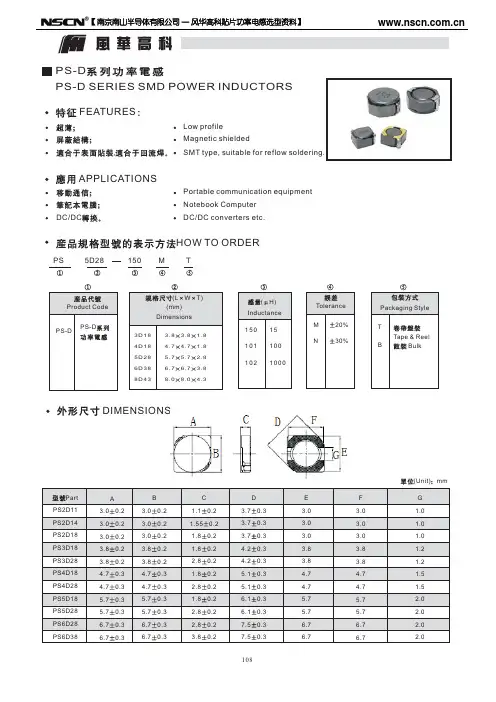
VE 3511/3516/3521/4532/5020/5835/5845/7835/7850/1040/1054TYPE● FEATURES:Various high power indrctors are superior To be high saturation for surface mounting ● 特性:具有高功率、强力高饱和电流、低阻抗、 小型化之特性。
● APPLICATIONS : Powder supply for VTR,OA equipmentDigital camera, LCD television set Notebook PC,portable communicationEquipments, DC/DC converters ,ect. ● 用途:录音机、OA 仪器、数码相机、液晶电视、 笔记型电脑、小型通信机器、DC/DC 变压器 之电源供应器等。
● PART NUMBERING SUSTEM(品名系统):● SHAPES AND DIMENSIONS(外形及尺寸):● SPECIFICATION (规格):mmTYPE(型式) A B C(max) D(ref)VE3511 3.0±0.3 1.15±0.3 3.5±0.31.0 VE3516 3.0±0.3 1.65±0.3 3.5±0.3 1.0 VE3521 3.0±0.32.1±0.33.5±0.3 1.0 VE45324.0±0.3 3.2±0.3 4.5±0.3 1.4 VE50205.2±0.3 2.1±0.3 5.8±0.3 1.6 VE5835 5.2±0.3 3.2±0.3 5.8±0.3 1.6 VE5845 5.2±0.3 4.5±0.3 5.8±0.3 1.6 VE7835 7.0±0.3 3.5±0.3 7.8±0.3 2.4 VE7850 7.0±0.3 5.0±0.3 7.8±0.3 2.4 VE10409.0±0.34.0±0.510.0±0.33.1VE3511-R47N 0.47 0.72 0.32 100KHzVE3511-R56N 0.56 0.85 0.20 100KHz VE3511-R68N 0.68 0.93 0.19 100KHzVE3511-R82N 0.82 1.02 0.185 100KHz VE3511-100K 10 1.15 0.18 100KHzVE3511-120K 12 1.28 0.175 100KHz VE3511-150K 15 1.32 0.172 100KHzVE3511-180K 18 1.45 0.17 100KHz VE3511-220K 22 1.55 0.162 100KHzVE3511-250K 25 1.62 0.160 100KHz VE3511-330K 33 1.70 0.150 100KHzVE3511-470K 47 1.75 0.150 100KHz VE3511-560K 56 1.82 0.145 100KHzVE3511-680K 68 1.88 0.142 100KHz VE3511-820K 82 1.92 0.140 100KHzVE3511-101K 100 2.00 0.138 100KHz VE3511-221K 220 2.10 0.136 100KHzVE3511-331K 330 2.18 0.132 100KHz VE3511-391K 390 2.45 0.130 100KHzVE3516 TYPEPART NUMBER.品名INDUCTANCE电感值(µH)DCR(max)直流电阻(Ω)IDC(max)定格电流(A)TEST FREQ.测试频率VE3516-2R2N2.2 0.10 1.8 100KHz VE3516-3R3N3.3 0.15 1.5 100KHzVE3516-4R7N4.7 0.12 1.2 100KHz VE3516-5R6N5.6 0.24 1.15 100KHzVE3516-6R8N6.8 0.26 1.1 100KHz VE3516-100K 10 0.38 0.8 100KHzVE3516-220K 22 0.65 0.6 100KHzVE3516-330K 33 0.85 0.45 100KHzVE3516-470K 47 1.20 0.35 100KHz This indicates the value of current when the inductance is 10% lower than its initial value at D.CVE3521-2R7M 2.7 0.100 1.90 100KHzVE3521-3R3M 3.3 0.120 1.80 100KHz VE3521-3R9M 3.9 0.130 1.70 100KHzVE3521-4R7M 4.7 0.150 1.40 100KHz VE3521-5R6M 5.6 0.180 1.30 100KHzVE3521-6R8M 6.8 0.190 1.20 100KHz VE3521-8R2M 8.2 0.215 1.10 100KHzVE3521-100K 10 0.23 0.76 100KHz VE3521-120K 12 0.27 0.685 100KHzVE3521-150K 15 0.31 0.635 100KHz VE3521-180K 18 0.41 0.525 100KHzVE3521-220K 22 0.47 0.500 100KHz VE3521-270K 27 0.66 0.405 100KHzVE3521-330K 33 0.76 0.380 100KHz VE3521-390K 39 0.85 0.355 100KHzVE3521-470K 47 0.97 0.330 100KHz VE3521-560K 56 1.25 0.290 100KHzVE3521-680K 68 1.45 0.275 100KHz VE3521-820K 82 1.85 0.235 100KHzVE3521-101K 100 2.20 0.220 100KHz VE3521-121K 120 2.90 0.185 100KHzVE3521-151K 150 3.40 0.170 100KHz VE3521-181K 180 3.90 0.165 100KHzVE3521-221K 220 4.50 0.155 100KHz VE3521-271K 270 6.00 0.135 100KHzVE3521-331K 330 7.00 0.125 100KHz VE3521-391K 390 7.80 0.115 100KHzThis indicates the value of current when the inductance is 10% lower than its initial value at D.C Superposition or D.C.current when at ⊿t=40℃ whichever is lower.直流重叠特性,规格内之IDC通过时电感值变化在初始值的-10%以内,温升40℃以内VE4532-1R4M 1.4 0.038 3.30 100KHz VE4532-1R8M 1.8 0.042 2.91 100KHz VE4532-2R2M 2.2 0.047 2.60 100KHz VE4532-2R7M 2.7 0.052 2.43 100KHz VE4532-3R3M 3.3 0.058 2.15 100KHz VE4532-3R9M 3.9 0.076 1.98 100KHz VE4532-4R7M 4.7 0.094 1.70 100KHz VE4532-5R6M 5.6 0.101 1.60 100KHz VE4532-6R8M 6.8 0.117 1.41 100KHz VE4532-8R2M 8.2 0.132 1.26 100KHz VE4532-100K 10 0.182 1.15 100KHz VE4532-120K 12 0.210 1.05 100KHz VE4532-150K 15 0.235 0.92 100KHz VE4532-180K 18 0.338 0.84 100KHz VE4532-220K 22 0.378 0.76 100KHz VE4532-270K 27 0.522 0.71 100KHz VE4532-330K 33 0.540 0.64 100KHz VE4532-390K 39 0.587 0.59 100KHz VE4532-470K 47 0.844 0.54 100KHz VE4532-560K 56 0.937 0.50 100KHz VE4532-680K 68 1.117 0.48 100KHz VE4532-820K 82 1.20 0.46 100KHz VE4532-121K 120 1.04 0.30 100KHz VE4532-152K 1500 15.0 0.05 100KHz VE4532-172K 1700 16.0 0.04 100KHz This indicates the value of current when the inductance is 10% lower than its initial value at D.C Superposition or D.C.current when at ⊿t=40℃ whichever is lower.直流重叠特性,规格内之IDC通过时电感值变化在初始值的-10%以内,温升40℃以内VE5020-2R2M 2.2 0.039 2.16 100KHz VE5020-2R7M 2.7 0.044 2.08 100KHz VE5020-3R3M 3.3 0.049 1.90 100KHz VE5020-3R9M 3.9 0.056 1.84 100KHz VE5020-4R7M 4.7 0.062 1.60 100KHz VE5020-5R6M 5.6 0.078 1.44 100KHz VE5020-6R8M 6.8 0.091 1.36 100KHz VE5020-8R2M 8.2 0.103 1.12 100KHz VE5020-100K 10 0.133 1.04 100KHz VE5020-120K 12 0.148 0.96 100KHz VE5020-150K 15 0.166 0.88 100KHz VE5020-180K 18 0.213 0.77 100KHz VE5020-220K 22 0.248 0.73 100KHz VE5020-270K 27 0.328 0.64 100KHz VE5020-330K 33 0.378 0.58 100KHz VE5020-390K 39 0.438 0.54 100KHz VE5020-470K 47 0.546 0.49 100KHz VE5020-560K 56 0.621 0.45 100KHz VE5020-680K 68 0.715 0.41 100KHz VE5020-820K 82 1.00 0.35 100KHz VE5020-101K 100 1.07 0.35 100KHz VE5020-121K 120 1.25 0.32 100KHz VE5020-151K 150 1.66 0.26 100KHz VE5020-181K 180 1.90 0.23 100KHz VE5020-221K 220 2.44 0.21 100KHz VE5020-271K 270 2.73 0.19 100KHz This indicates the value of current when the inductance is 10% lower than its initial value at D.C Superposition or D.C.current when at ⊿t=40℃ whichever is lower.直流重叠特性,规格内之IDC通过时电感值变化在初始值的-10%以内,温升40℃以内VE5835-1R0M 1.0 0.03 4.50 100KHz VE5835-1R2M 1.2 0.03 4.20 100KHz VE5835-1R5M 1.5 0.03 4.10 100KHz VE5835-1R8M 1.8 0.03 3.70 100KHz VE5835-2R2M 2.2 0.03 3.50 100KHz VE5835-2R7M 2.7 0.04 3.20 100KHz VE5835-3R3M 3.3 0.05 2.80 100KHz VE5835-3R9M 3.9 0.06 2.60 100KHz VE5835-4R7M 4.7 0.07 2.50 100KHz VE5835-5R6M 5.6 0.08 2.40 100KHz VE5835-6R8M 6.8 0.09 2.20 100KHz VE5835-8R2M 8.2 0.10 2.00 100KHz VE5835-100K 10 0.12 1.80 100KHz VE5835-120K 12 0.13 1.75 100KHz VE5835-150K 15 0.15 1.70 100KHz VE5835-180K 18 0.18 1.60 100KHz VE5835-220K 22 0.22 1.50 100KHz VE5835-270K 27 0.24 1.40 100KHz VE5835-330K 33 0.30 1.10 100KHz VE5835-390K 39 0.40 1.00 100KHz VE5835-470K 47 0.43 0.90 100KHz VE5835-560K 56 0.50 0.85 100KHz VE5835-680K 68 0.60 0.80 100KHz VE5835-820K 82 0.80 0.65 100KHz VE5835-101K 100 0.90 0.60 100KHz VE5835-121K 120 1.00 0.58 100KHz VE5835-151K 150 1.30 0.43 100KHz VE5835-181K 180 1.50 0.41 100KHz VE5835-221K 220 2.00 0.38 100KHz VE5835-271K 270 2.50 0.35 100KHz VE5835-331K 330 3.20 0.28 100KHz VE5835-391K 390 3.50 0.26 100KHz VE5835-471K 470 4.20 0.20 100KHz VE5835-561K 560 4.50 0.19 100KHz VE5835-681K 680 6.00 0.18 100KHz VE5835-821K 820 6.50 0.15 100KHz VE5835-102K 1000 8.00 0.13 100KHz This indicates the value of current when the inductance is 10% lower than its initial value at D.C Superposition or D.C.current when at ⊿t=40℃ whichever is lower.VE5845-1R0M 1.0 0.015 5.90 100KHz VE5845-1R2M 1.2 0.020 5.20 100KHzVE5845-1R5M 1.5 0.025 4.70 100KHzVE5845-1R8M 1.8 0.030 4.00 100KHzVE5845-2R2M 2.2 0.035 3.80 100KHzVE5845-2R7M 2.7 0.040 3.40 100KHzVE5845-3R3M 3.3 0.045 3.30 100KHzVE5845-3R9M 3.9 0.050 2.90 100KHzVE5845-4R7M 4.7 0.060 2.80 100KHzVE5845-5R6M 5.6 0.070 2.40 100KHzVE5845-6R8M 6.8 0.080 2.10 100KHzVE5845-8R2M 8.2 0.090 2.00 100KHzVE5845-100M 10 0.10 1.44 100KHzVE5845-120M 12 0.12 1.40 100KHzVE5845-150M 15 0.14 1.30 100KHzVE5845-180M 18 0.15 1.23 100KHzVE5845-220M 22 0.18 1.11 100KHzVE5845-270M 27 0.20 0.97 100KHzVE5845-330L 33 0.23 0.88 100KHzVE5845-390L 39 0.32 0.80 100KHzVE5845-470L 47 0.37 0.72 100KHzVE5845-560K 56 0.42 0.68 100KHzVE5845-680K 68 0.46 0.61 100KHzVE5845-820K 82 0.60 0.58 100KHzVE5845-101K 100 0.70 0.52 100KHzVE5845-121K 120 0.93 0.48 100KHzVE5845-151K 150 1.10 0.40 100KHzVE5845-181K 180 1.38 0.38 100KHzVE5845-221K 220 1.57 0.35 100KHzVE5845-271K 270 1.65 0.32 100KHzVE5845-331K 330 1.70 0.28 100KHzVE5845-391K 390 1.80 0.26 100KHzVE5845-471K 470 2.30 0.23 100KHzVE5845-561K 560 2.50 0.20 100KHzVE5845-681K 680 3.00 0.19 100KHzVE5845-821K 820 4.50 0.16 100KHzVE5845-102K 1000 4.80 0.14 100KHzThis indicates the value of current when the inductance is 10% lower than its initial value at D.C Superposition or D.C.current when at ⊿t=40℃ whichever is lower.VE7835-100K 10 0.080 1.44 100KHz VE7835-120K 12 0.090 1.39 100KHzVE7835-150K 15 0.100 1.24 100KHzVE7835-180K 18 0.110 1.12 100KHzVE7835-220K 22 0.130 1.07 100KHzVE7835-270K 27 0.150 0.94 100KHzVE7835-330K 33 0.170 0.85 100KHz VE7835-390K 39 0.220 0.74 100KHzVE7835-470K 47 0.250 0.68 100KHzVE7835-560K 56 0.280 0.64 100KHzVE7835-680K 68 0.330 0.59 100KHzVE7835-820K 82 0.410 0.54 100KHzVE7835-101K 100 0.480 0.51 100KHz VE7835-121K 120 0.540 0.49 100KHzVE7835-151K 150 0.750 0.40 100KHzVE7835-181K 180 1.020 0.36 100KHzVE7835-221K 220 1.200 0.31 100KHzVE7835-271K 270 1.310 0.29 100KHzVE7835-331K 330 1.500 0.28 100KHz This indicates the value of current when the inductance is 10% lower than its initial value at D.C Superposition or D.C.current when at ⊿t=40℃ whichever is lower.直流重叠特性,规格内之IDC通过时电感值变化在初始值的-10%以内,温升40℃以内VE7850-120M 12 0.080 2.00 100KHz VE7850-150M 15 0.090 1.80 100KHz VE7850-180M 18 0.100 1.60 100KHz VE7850-220M 22 0.110 1.50 100KHz VE7850-270M 27 0.120 1.30 100KHz VE7850-330M 33 0.130 1.20 100KHz VE7850-390M 39 0.160 1.10 100KHz VE7850-470M 47 0.180 1.10 100KHz VE7850-560K 56 0.240 0.94 100KHz VE7850-680K 68 0.280 0.85 100KHz VE7850-820K 82 0.370 0.78 100KHz VE7850-101K 100 0.430 0.72 100KHz VE7850-121K 120 0.470 0.66 100KHz VE7850-151K 150 0.640 0.58 100KHz VE7850-181K 180 0.710 0.51 100KHz VE7850-221K 220 0.960 0.49 100KHz VE7850-271K 270 1.110 0.42 100KHz VE7850-331K 330 1.260 0.40 100KHz VE7850-391K 390 1.770 0.36 100KHz VE7850-471K 470 1.960 0.34 100KHz This indicates the value of current when the inductance is 10% lower than its initial value at D.C Superposition or D.C.current when at ⊿t=40℃ whichever is lower.直流重叠特性,规格内之IDC通过时电感值变化在初始值的-10%以内,温升40℃以内VE1040-120K 12 0.061 2.13 100KHz VE1040-150K 15 0.070 1.87 100KHz VE1040-180K 18 0.081 1.73 100KHz VE1040-220K 22 0.088 1.60 100KHz VE1040-270K 27 0.100 1.44 100KHz VE1040-330K 33 0.120 1.26 100KHz VE1040-390K 39 0.151 1.20 100KHz VE1040-470K 47 0.170 1.10 100KHz VE1040-560K 56 0.199 1.01 100KHz VE1040-680K 68 0.223 0.91 100KHz VE1040-820K 82 0.252 0.85 100KHz VE1040-101K 100 0.344 0.74 100KHz VE1040-121K 120 0.396 0.69 100KHz VE1040-151K 150 0.544 0.61 100KHz VE1040-181K 180 0.621 0.56 100KHz VE1040-221K 220 0.721 0.53 100KHz VE1040-271K 270 0.949 0.45 100KHz VE1040-331K 330 1.100 0.42 100KHz VE1040-391K 390 1.245 0.38 100KHz VE1040-471K 470 1.526 0.35 100KHz VE1040-561K 560 1.904 0.32 100KHz This indicates the value of current when the inductance is 10% lower than its initial value at D.C Superposition or D.C.current when at ⊿t=40℃ whichever is lower.直流重叠特性,规格内之IDC通过时电感值变化在初始值的-10%以内,温升40℃以内VE1054 TYPEPART NUMBER.品名INDUCTANCE电感值(µH)DCR(max)直流电阻(Ω)IDC(max)定格电流(A)TEST FREQ.测试频率VE1054 -100M 10 0.060 2.60 100KHz VE1054-120M 12 0.070 2.45 100KHz VE1054-150M 15 0.080 2.27 100KHz VE1054-180M 18 0.090 2.15 100KHz VE1054-220M 22 0.100 1.95 100KHz VE1054-270M 27 0.110 1.76 100KHz VE1054-330L 33 0.120 1.50 100KHz VE1054-390L 39 0.140 1.37 100KHz VE1054-470L 47 0.170 1.28 100KHz VE1054-560K 56 0.190 1.17 100KHz VE1054-680K 68 0.220 1.11 100KHz VE1054-820K 82 0.250 1.00 100KHz VE1054-101K 100 0.350 0.97 100KHz VE1054-121K 120 0.400 0.89 100KHz VE1054-151K 150 0.470 0.78 100KHz VE1054-181K 180 0.630 0.72 100KHz VE1054-221K 220 0.730 0.66 100KHz VE1054-271K 270 0.970 0.57 100KHz VE1054-331K 330 1.150 0.52 100KHz VE1054-391K 390 1.300 0.48 100KHz VE1054-471K 470 1.480 0.42 100KHz VE1054-561K 560 1.900 0.33 100KHz VE1054-681K 680 2.250 0.28 100KHz VE1054-821K 820 2.550 0.24 100KHz This indicates the value of current when the inductance is 10% lower than its initial value at D.C Superposition or D.C.current when at ⊿t=40℃ whichever is lower.直流重叠特性,规格内之IDC通过时电感值变化在初始值的-10%以内,温升40℃以内卷轴尺寸 (REEL DIMENSIONS) 如下图:卷轮尺寸(REEL DIMENSIONS)一般公差±0.5mm型号unit ФA ФB ФC W Dmm 330 100 13.5 12.5 18.5 Φ13”REEL-12Ginch 13.0 3.94 0.482 0.492 0.728mm 330 100 13.5 16.5 22.5 Φ13”REEL-16Ginch 13.0 3.94 0.482 0.650 0.889mm 330 100 13.5 24.5 30.5 Φ13”REEL-24Ginch 13.0 3.94 0.482 0.965 1.201◆ 包装(Packing)品名规格卷轮型号每卷包装数量(PCS)每啤盒包装数量(PCS)(尺寸:338x338x78mm)每箱包装数量(PCS)(尺寸:350x350x170mm)VE3511 Φ13”REEL-12G 3000 12000 24000 VE3516 Φ13”REEL-12G 3000 12000 24000 VE3521 Φ13”REEL-12G 3000 12000 24000 VE4532 Φ13”REEL-12G 2000 8000 16000 VE5020 Φ13”REEL-12G 3000 12000 24000 VE5835 Φ13”REEL-12G 1500 6000 12000 VE5845 Φ13”REEL-12G 1500 6000 12000 VE7835 Φ13”REEL-16G 1000 3000 6000VE7850 Φ13”REEL-16G 1000 3000 6000 VE1040 Φ13”REEL-24G 1000 2000 4000VE1054 Φ13”REEL-24G 1000 2000 4000 Special inquiries besides the above common used types can be met on your requirement超出以上规格的特殊要求也可满足。
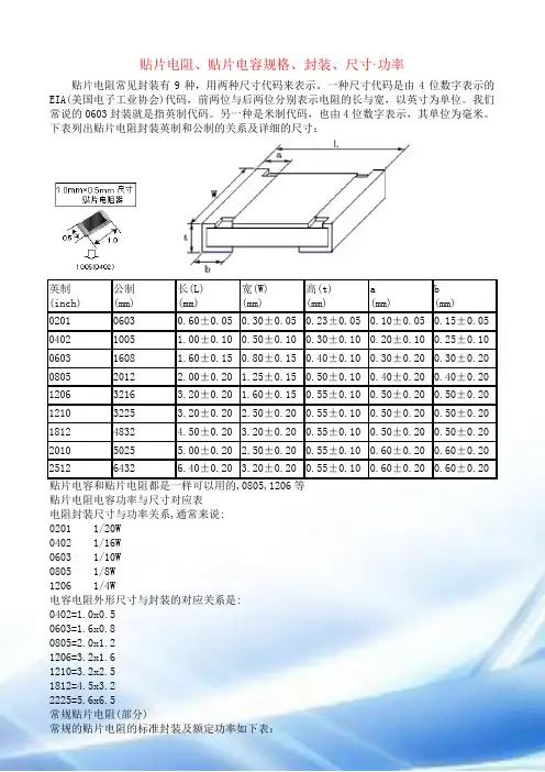
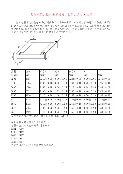
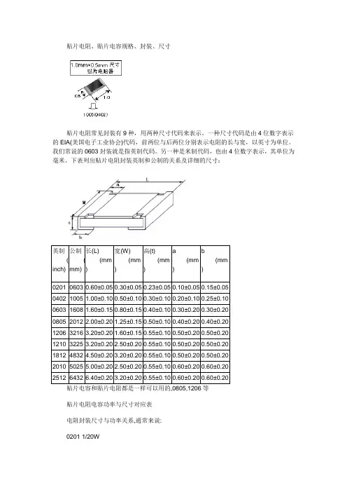
贴片电阻、贴片电容规格、封装、尺寸·功率贴片电阻常见封装有9种,用两种尺寸代码来表示。
一种尺寸代码是由4位数字表示的EIA(美国电子工业协会)代码,前两位与后两位分别表示电阻的长与宽,以英寸为单位。
我们常说的0603封装就是指英制代码。
另一种是米制代码,也由4位数字表示,其单位为毫米。
下表列出贴片电阻封装英制和公制的关系及详细的尺寸:英制(inch) 公制(mm)长(L)(mm)宽(W)(mm)高(t)(mm)a(mm)b(mm)0201 0603 0.60±0.050.30±0.050.23±0.050.10±0.050.15±0.05 0402 1005 1.00±0.100.50±0.100.30±0.100.20±0.100.25±0.10 0603 1608 1.60±0.150.80±0.150.40±0.100.30±0.200.30±0.20 0805 2012 2.00±0.20 1.25±0.150.50±0.100.40±0.200.40±0.20 1206 3216 3.20±0.20 1.60±0.150.55±0.100.50±0.200.50±0.20 1210 3225 3.20±0.20 2.50±0.200.55±0.100.50±0.200.50±0.20 1812 4832 4.50±0.20 3.20±0.200.55±0.100.50±0.200.50±0.20 2010 5025 5.00±0.20 2.50±0.200.55±0.100.60±0.200.60±0.20 2512 6432 6.40±0.20 3.20±0.200.55±0.100.60±0.200.60±0.20贴片电阻电容功率与尺寸对应表电阻封装尺寸与功率关系,通常来说:0201 1/20W0402 1/16W0603 1/10W0805 1/8W1206 1/4W电容电阻外形尺寸与封装的对应关系是:0402=1.0x0.50603=1.6x0.80805=2.0x1.21206=3.2x1.61210=3.2x2.51812=4.5x3.22225=5.6x6.5常规贴片电阻(部分)常规的贴片电阻的标准封装及额定功率如下表:英制(mil) 公制(mm) 额定功率(W)@ 70°C0201 0603 1/200402 1005 1/160603 1608 1/100805 2012 1/81206 3216 1/41210 3225 1/31812 4832 1/22010 5025 3/42512 6432 1国内贴片电阻的命名方法:1、5%精度的命名:RS-05K102JT2、1%精度的命名:RS-05K1002FTR -表示电阻S -表示功率0402是1/16W、0603是1/10W、0805是1/8W、1206是1/4W、 1210是1/3W、1812是1/2W、2010是3/4W、2512是1W。
贴片电阻规格、封装、尺寸ChipR Dimensions 、Footprint简述基本结构分类规格、封装、尺寸额定功率及工作电压阻值,标准阻值标识规格书、生产厂家命名方法价格、报价创建时间:2005-12-30 最后修改时间:2006-10-29贴片电阻套件为方便学生、研发人员试验和产品试制,特推出片式电阻系列套件。
简述我们常说的贴片电阻(SMD Resistor)叫"片式固定电阻器"(Chip Fixed Resistor),又叫"矩形片状电阻"(Rectangular Chip Resistors),是由ROHM公司发明并最早推出市场的。
特点是耐潮湿,耐高温,可靠度高,外观尺寸均匀,精确且温度系数与阻值公差小。
按生产工艺分厚膜(Thick Film Chip Resistors)、薄膜(Thin Film Chip Resistors )两种。
厚膜是采用丝网印刷将电阻性材料淀积在绝缘基体(例如玻璃或氧化铝陶瓷)上,然后烧结形成的。
我们通常所见的多为厚膜片式电阻,精度范围±0.5% ~ 10%,温度系数:±50PPM/℃~ ±400PPM/℃。
薄膜是在真空中采用蒸发和溅射等工艺将电阻性材料淀积在绝缘基体工艺(真空镀膜技术)制成,特点是低温度系数(±5PPM/℃),高精度(±0.01%~±1%)。
封装有:0201,0402,0603,0805,1206,1210,1812,2010,2512。
其常规系列的精度为5%,1%。
阻值范围从0.1欧姆到20M欧姆。
标准阻值有E24,E96系列。
功率有1/20W、1/16W、1/8W、1/10W、1/4W、1/2W、1W。
特性:•体积小,重量轻•适合波峰焊和回流焊•机械强度高,高频特性优越•常用规格价格比传统的引线电阻还便宜•生产成本低,配合自动贴片机,适合现代电子产品规模化生产使用状况:由于价格便宜,生产方便,能大面积减少PCB面积,减少产品外观尺寸,现在已取代绝大部分传统引线电阻。
贴片电阻、贴片电容规格、封装、尺寸·功率贴片电阻常见封装有9种,用两种尺寸代码来表示。
一种尺寸代码是由4位数字表示的EIA(美国电子工业协会)代码,前两位与后两位分别表示电阻的长与宽,以英寸为单位。
我们常说的0603封装就是指英制代码。
另一种是米制代码,也由4位数字表示,其单位为毫米。
下表列出贴片电阻封装英制和公制的关系与详细的尺寸:英制(inch) 公制(mm)长(L)(mm)宽(W)(mm)高(t)(mm)a(mm)b(mm)0201 0603 0.60±0.050.30±0.050.23±0.050.10±0.050.15±0.05 0402 1005 1.00±0.100.50±0.100.30±0.100.20±0.100.25±0.10 0603 1608 1.60±0.150.80±0.150.40±0.100.30±0.200.30±0.20 0805 2012 2.00±0.20 1.25±0.150.50±0.100.40±0.200.40±0.20 1206 3216 3.20±0.20 1.60±0.150.55±0.100.50±0.200.50±0.20 1210 3225 3.20±0.20 2.50±0.200.55±0.100.50±0.200.50±0.20 1812 4832 4.50±0.20 3.20±0.200.55±0.100.50±0.200.50±0.20 2010 5025 5.00±0.20 2.50±0.200.55±0.100.60±0.200.60±0.20 2512 6432 6.40±0.20 3.20±0.200.55±0.100.60±0.200.60±0.20贴片电阻电容功率与尺寸对应表电阻封装尺寸与功率关系,通常来说:0201 1/20W0402 1/16W0603 1/10W0805 1/8W1206 1/4W电容电阻外形尺寸与封装的对应关系是:常规贴片电阻(局部)常规的贴片电阻的标准封装与额定功率如下表:英制(mil) 公制(mm) 额定功率(W) 70°C0201 0603 1/2004021005 1/160603 1608 1/100805 2012 1/81206 3216 1/41210 3225 1/31812 4832 1/22010 5025 3/42512 6432 1国贴片电阻的命名方法:1、5%精度的命名:RS-05K102JT2、1%精度的命名:RS-05K1002FTR -表示电阻S -表示功率0402是1/16W、0603是1/10W、0805是1/8W、1206是1/4W、 1210是1/3W、1812是1/2W、2010是3/4W、2512是1W。
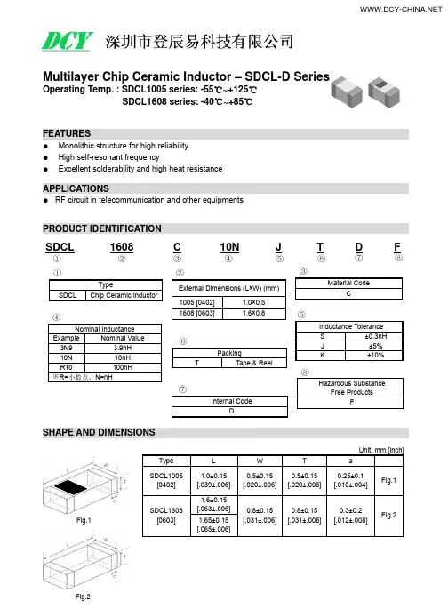
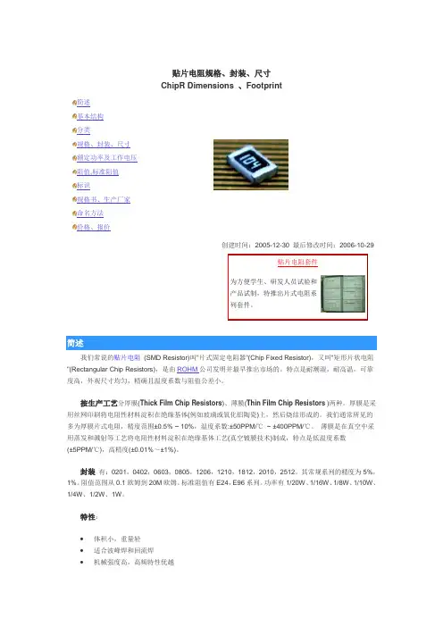
Multilayer Chip Ceramic Inductor – SDCL-D SeriesOperating Temp. : SDCL1005 series: -55℃~+125℃SDCL1608 series: -40℃~+85℃FEATURES●Monolithic structure for high reliability● High self-resonant frequency● Excellent solderability and high heat resistanceAPPLICATIONS●RF circuit in telecommunication and other equipmentsPRODUCT IDENTIFICATIONSHAPE AND DIMENSIONSUnit: mm [inch]Type L W T a SDCL1005[0402]1.0±0.15 [.039±.006]0.5±0.15 [.020±.006]0.5±0.15 [.020±.006]0.25±0.1 [.010±.004]Fig.1SDCL1608 [0603] 1.6±0.15 [.063±.006]0.8±0.15 [.031±.006]0.8±0.15 [.031±.006] 0.3±0.2 [.012±.008]Fig.21.65±0.15 [.065±.006]②External Dimensions (L×W) (mm)1005 [0402] 1.0×0.5 1608 [0603] 1.6×0.8 ① TypeSDCL Chip Ceramic Inductor③ Material Code C ④ Nominal InductanceExample Nominal Value 3N9 3.9nH 10N 10nH R10 100nH※R=小数点,N=nH ⑤Inductance Tolerance S ±0.3nH J ±5%K ±10% ⑥Packing T Tape & Reel⑧Hazardous Substance Free ProductsFSDCL ① 1608② C ③ 10N ④ J ⑤ T⑥ D ⑦ F ⑧ ⑦ Internal Code DFig.1Fig.2规格特性 SPECIFICATIONSSDCL1005-D SeriesPart NumberInductanceMin.QualityFactor L,Q Test Freq. L/Q Typical Q @ Freq. (MHz)Min.Self-resonantFrequency Max. DCResistanceMax. Rated Current1008001000Units nH - MHz - MHz Ω mA Symbol L Q Freq Q S.R.F DCR IrSDCL1005C1N0STDF 1.0±0.3 8 100 11 34 36 10000 0.10 400 SDCL1005C1N1STDF 1.1±0.3 8 100 11 34 36 10000 0.10 400 SDCL1005C1N2STDF 1.2±0.3 8 100 11 34 36 10000 0.10 400 SDCL1005C1N3STDF 1.3±0.3 8 100 11 34 36 10000 0.10 400 SDCL1005C1N5STDF 1.5±0.3 8 100 11 34 36 6000 0.10 300 SDCL1005C1N6STDF 1.6±0.3 8 100 11 32 35 6000 0.10 300 SDCL1005C1N8STDF 1.8±0.3 8 100 11 30 34 6000 0.10 300 SDCL1005C2N0STDF 2.0±0.3 8 100 10 29 33 6000 0.20 300 SDCL1005C2N2STDF 2.2±0.3 8 100 10 29 33 6000 0.20 300 SDCL1005C2N4STDF 2.4±0.3 8 100 10 29 32 6000 0.20 300 SDCL1005C2N7STDF 2.7±0.3 8 100 10 29 32 6000 0.20 300 SDCL1005C3N0STDF 3.0±0.3 8 100 10 29 32 6000 0.20 300 SDCL1005C3N3STDF 3.3±0.3 8 100 10 29 32 6000 0.20 300 SDCL1005C3N6STDF 3.6±0.3 8 100 10 28 31 4000 0.20 300 SDCL1005C3N9STDF 3.9±0.3 8 100 10 28 31 4000 0.20 300 SDCL1005C4N3STDF 4.3±0.3 8 100 10 28 31 4000 0.20 300 SDCL1005C4N7STDF 4.7±0.3 8 100 10 28 31 4000 0.20 300 SDCL1005C5N1STDF 5.1±0.3 8 100 10 28 30 4000 0.30 300 SDCL1005C5N6STDF 5.6±0.3 8 100 10 28 30 4000 0.30 300 SDCL1005C6N2STDF 6.2±0.3 8 100 10 27 30 3900 0.30 300 SDCL1005C6N8□TDF 6.8 8 100 10 27 30 3900 0.30 300 SDCL1005C7N5□TDF 7.5 8 100 10 27 30 3700 0.40 300 SDCL1005C8N2□TDF 8.2 8 100 10 27 30 3600 0.40 300 SDCL1005C9N1□TDF 9.1 8 100 10 27 30 3400 0.40 300 SDCL1005C10N □TDF 10 8 100 10 27 30 3200 0.40 300 SDCL1005C12N □TDF 12 8 100 10 26 29 2700 0.50 300 SDCL1005C15N □TDF 15 8 100 10 26 28 2300 0.50 300 SDCL1005C18N □TDF 18 8 100 10 25 27 2100 0.60 300 SDCL1005C20N □TDF 20 8 100 10 25 26 2000 0.60 300 SDCL1005C22N □TDF 22 8 100 10 25 25 1900 0.60 300 SDCL1005C27N □TDF 27 8 100 10 25 23 1600 0.70 300 SDCL1005C33N □TDF 33 8 100 10 22 22 1300 0.80 200 SDCL1005C39N □TDF 39 8 100 10 22 19 1200 1.00 200 SDCL1005C43N □TDF 43 8 100 10 21 16 1100 1.10 200 SDCL1005C47N □TDF 47 8 100 10 21 16 1000 1.10 200 SDCL1005C56N □TDF 56 8 100 10 18 13 750 1.20 200 SDCL1005C68N □TDF 68 8 100 10 18 9 750 1.40 180 SDCL1005C82N □TDF 82 8 100 10 13 - 750 2.40 150 SDCL1005CR10□TDF 100 8 100 10 12 - 700 2.60 150SDCL1005CR12□TDF 120 8 100 10 - - 600 2.80 150SDCL1005CR15□TDF 150 8 100 10 - - 550 3.20 100 SDCL1005CR18□TDF 180 8 100 10 - - 500 3.70 100 SDCL1005CR22□TDF 220 8 100 12 - - 450 4.00 100 SDCL1005CR27□TDF 270 8 100 12 - - 400 4.50 100 SDCL1005CR30□TDF 300 6 50 12 - - 350 7.00 50 SDCL1005CR33□TDF 330 6 50 8 - - 350 7.00 50 SDCL1005CR36□TDF 360 6 50 8 - - 300 7.50 50※□: Please specify the inductance tolerance code (J=±5%, K=±10%). The product with tolerance less than ±5%, ±10% is also available. Please contact your local sales.SPECIFICATIONS SDCL1608-D SeriesPart Number InductanceMin.QualityFactorL,Q TestFreq.L/Q Typical Q @ Freq. (MHz)Min.Self-resonantFrequencyMax. DCResistanceMax.RatedCurrent 100800 1000Units nH - MHz - MHz ΩmASymbol L Q Freq Q S.R.F DCR IrSDCL1608C1N0STDF 1.0±0.3 8 100 13 70 80 10000 0.05 500 SDCL1608C1N2STDF 1.2±0.3 8 100 13 60 70 10000 0.05 500 SDCL1608C1N5STDF 1.5±0.3 8 100 13 47 68 6000 0.10 500 SDCL1608C1N8STDF 1.8±0.3 8 100 13 45 61 6000 0.10 500 SDCL1608C2N2STDF 2.2±0.3 8 100 13 45 60 6000 0.10 500 SDCL1608C2N7STDF 2.7±0.3 10 100 13 44 55 6000 0.12 500 SDCL1608C3N3STDF 3.3±0.3 10 100 13 43 50 6000 0.15 500 SDCL1608C3N9STDF 3.9±0.3 10 100 13 43 50 6000 0.16 500 SDCL1608C4N7STDF 4.7±0.3 10 100 13 43 50 6000 0.20 500 SDCL1608C5N6STDF 5.6±0.3 10 100 14 42 48 5000 0.25 500 SDCL1608C6N8□TDF 6.8 10 100 1443 50 5000 0.30 500 SDCL1608C8N2□TDF 8.2 10 100 1443 48 4500 0.35 500 SDCL1608C10N□TDF 10 12 100154550 3500 0.40 300 SDCL1608C12N□TDF 12 12 100184850 3000 0.45 300 SDCL1608C15N□TDF 15 12 100184850 2300 0.50 300 SDCL1608C18N□TDF 18 12 100164851 2200 0.55 300 SDCL1608C22N□TDF 22 12 100164548 2000 0.60 300 SDCL1608C27N□TDF 27 12 100164545 1700 0.65 300 SDCL1608C33N□TDF 33 12 100164541 1500 0.70 300 SDCL1608C39N□TDF 39 12 100174048 1400 0.70 300 SDCL1608C47N□TDF 47 12 100173535 1200 0.70 300 SDCL1608C56N□TDF 56 12 100173530 1100 0.75 300 SDCL1608C68N□TDF 68 12 100173020 900 0.85 300 SDCL1608C82N□TDF 82 8 1001522 - 800 1.00 300 SDCL1608CR10□TDF 100 8 1001516 - 700 1.20 300 SDCL1608CR12□TDF* 120 8 50 15 - - 600 1.40 200 SDCL1608CR15□TDF* 150 8 50 15 - - 500 1.60 200 SDCL1608CR18□TDF* 180 8 50 15 - - 400 1.90 200 SDCL1608CR22□TDF* 220 8 50 15 - - 350 2.40 200 SDCL1608CR27□TDF* 270 8 50 16 - - 350 2.60 150 SDCL1608CR33□TDF* 330 8 50 16 - - 350 2.80 150 SDCL1608CR39□TDF* 390 8 50 16 - - 300 3.20 150 SDCL1608CR43□TDF* 430 8 50 16 - - 280 3.40 150 SDCL1608CR47□TDF* 470 8 50 15 - - 250 3.60 150 SDCL1608CR56□TDF* 560 8 50 15 - - 250 4.00 100 SDCL1608CR68□TDF* 680 8 50 15 - - 250 4.50 100※□: Please specify the inductance tolerance code (J=±5%, K=±10%). The product with tolerance less than ±5%, ±10% is also available. Please contact your local sales.※*: The length: 1.65±0.15mm, for others: 1.60±0.15mm.TYPICAL ELECTRICAL CHARACTERISTICSSDCL1005-D TYPE SDCL1005-D TYPEFrequency(MHz)110I n d u c t a n c e (n H )Frequency(MHz)QSDCL1608-D TYPE SDCL1608-D TYPEFrequency(MHz)110I n d u c t a n c e (n H )Frequency(MHz)Q。
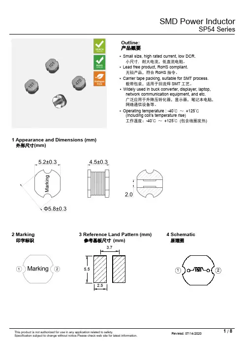
Outline:产品概要▪Small size,high rated current,low DCR.小尺寸,耐大电流,低直流电阻。
▪Lead free product,RoHS compliant.无铅产品,符合RoHS 指令。
▪Carrier tape packing,suitable for SMT process.载带包装,适用于回流焊SMT 工艺。
▪Widely used in buck converter,displayer,laptop,network communication equipment,and etc.广泛应用于升降压转化器,显示器,笔记本电脑,网络通信设备等。
▪Operating temperature :-40℃~+125℃(Including coil’s temperature rise)工作温度:-40℃~+125℃(包含线圈发热)1Appearance and Dimensions (mm)外形尺寸(mm)2Marking3Reference Land Pattern (mm)4Schematic印字标识参考基板尺寸(mm)原理图5.52.53.7215Electrical Characteristics电气特性Part No.Inductance (μH)D.C.R.(mΩ)Saturation current (A)Temperature rise current (A)■All data is tested based on 25℃ambient temperature.所有数据基于环境温度25℃条件下测试。
※1Inductance measure condition at 1kHz,0.25V.电感测试条件为1kHz,0.25V 。
※2Saturation current :the actual value of DC current when the inductance decrease 20%of its initial value.饱和电流:电感值下降其初始值的20%时所加载的实际直流电流值。
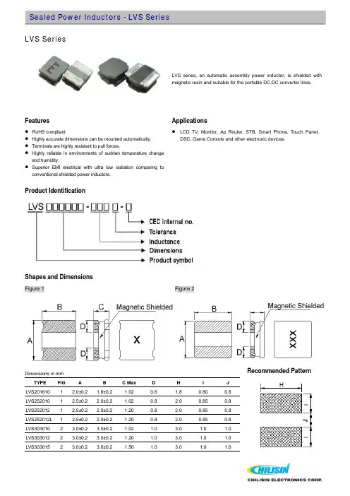
LVS SeriesLVS series, an automatic assembly power inductor, is shielded with magnetic resin and suitable for the portable DC-DC converter lines.Features Applications● RoHS compliant● Highly accurate dimensions can be mounted automatically. ● Terminals are highly resistant to pull forces.● Highly reliable in environments of sudden temperature change and humidity.● Superior EMI electrical with ultra low radiation comparing to conventional shielded power inductors.● LCD TV, Monitor, Ap Router, STB, Smart Phone, Touch Panel,DSC, Game Console and other electronic devices.Product IdentificationShapes and DimensionsFigure 1Figure 2Recommended PatternDimensions in mmTYPE FIG AB C Max DHIJLVS201610 1 2.0±0.2 1.6±0.2 1.02 0.6 1.8 0.80 0.8 LVS252010 1 2.5±0.2 2.0±0.2 1.02 0.8 2.0 0.85 0.8 LVS252012 1 2.5±0.2 2.0±0.2 1.20 0.8 2.0 0.85 0.8 LVS252012L 1 2.5±0.2 2.0±0.2 1.20 0.8 2.0 0.85 0.8 LVS303010 2 3.0±0.2 3.0±0.2 1.02 1.0 3.0 1.0 1.0 LVS303012 2 3.0±0.2 3.0±0.2 1.20 1.0 3.0 1.0 1.0 LVS3030152 3.0±0.23.0±0.21.50 1.0 3.0 1.0 1.0Shapes and DimensionsFigure 3 Figure 4Recommended Pattern Dimensions in mmMax D E H I J TYPE FIG A B CLVS404018 3 4.0±0.2 4.0±0.2 1.8±0.2 1.3±0.3 3.6 3.7 1.2 1.6LVS505020 4 5.0±0.2 5.0±0.2 2.0±0.2 1.8±0.3 4.0 4.0 1.5 2.1LVS505040 4 5.0±0.2 5.0±0.2 4.0±0.2 1.6±0.3 4.0 4.0 1.5 2.1LVS606020 4 6.0±0.2 6.0±0.2 2.0±0.2 1.7±0.3 5.0 5.7 1.6 3.1LVS606028 3 6.0±0.2 6.0±0.2 2.8±0.2 1.9±0.3 4.8 5.7 1.6 3.1LVS606045 4 6.0±0.2 6.0±0.2 4.5+0.2-0.30 1.8±0.3 5.0 5.7 1.6 3.1LVS808040 4 8.0±0.2 8.0±0.2 4.0±0.2 2.3±0.3 6.3 7.5 2.1 3.8Part NumberInductance(uH)Test Frequency (MHz) Tolerance (±%)RDC (Ω) ±30% Isat (mA)Typ Irms (mA)Typ MarkingLVS201610-1R0□-N 1.0 1 20, 30 0.17 1400 1600 A LVS201610-1R5□-N 1.5 1 20, 30 0.26 1100 1400 B LVS201610-2R2□-N 2.2120, 300.3210001200CLVS201610-3R3□-N 3.3 1 20, 30 0.51 820 900 D LVS201610-4R7□-N 4.7 1 20, 30 0.67 680 800 E LVS201610-5R6□-N 5.6 1 20, 30 0.72 650 800 F LVS201610-6R8□-N 6.8 1 20, 30 0.97 560 700 G LVS201610-100□-N 10 1 20, 30 1.45 470 580 H LVS201610-220□-N 22 1 20, 30 2.90 310 400 I● When ordering, please specify tolerance and packaging codes. ● Tolerance : T =±30% , M = ±20%● L : Agilent/HP4287A+ Agilent/HP16197A, 1MHz 200mV ● RDC : Digital Milliohm Meter Chroma 16502,or equivalent ● Isat & Irms : Agilent/HP4284A, 1MHz 200mV● Isat for Inductance drop 30% from its value without current. ● Irms for a 40℃ rise above 25℃ ambient.● Operating temperature range from -25℃ to 105℃.Test Instruments :HP4291A Material/Impedance AnalyzerInductance vs. DC Current05101520250200400600800100012001400160018002000DC Current(mA)L (u H )Temperature Change vs. DC Current10203040506070809010003006009001200150018002100DC Current(mA)△T (℃)Part NumberInductance(uH)Test Frequency (MHz) Tolerance (±%)RDC (Ω) ±30%Isat (mA)Typ Irms (mA)Typ MarkingLVS252010-1R0□-N 1.0 1 20, 30 0.093 2200 2200 A LVS252010-1R5□-N 1.5 1 20, 30 0.148 1900 1800 B LVS252010-2R2□-N 2.2 1 20, 30 0.178 **** **** C LVS252010-3R3□-N 3.3 1 20, 30 0.286 1220 1340 D LVS252010-4R7□-N 4.7120, 30 0.42110401020ELVS252010-5R6□-N 5.6 1 20, 30 0.481 920 840 F LVS252010-6R8□-N 6.8 1 20, 30 0.598 900 880 G LVS252010-100□-N 10 1 20, 30 0.797 740 820 H LVS252010-220□-N 22 1 20, 30 1.839 500 520 I● When ordering, please specify tolerance and packaging codes. ● Tolerance : T = ±30% , M = ±20% ● Packaging: Clear tape and reel {standard}.● L : Agilent/HP4287A+ Agilent/HP16197A, 1MHz 200mV ● RDC : Digital Milliohm Meter Chroma 16502,or equivalent ● Isat & Irms : Agilent/HP4284A, 1MHz 200mV● Isat for Inductance drop 30% from its value without current. ● Irms for a 40℃ rise above 25℃ ambient.● Operating temperature range from -25℃ to 105℃.Test Instruments :HP4291A Material/Impedance AnalyzerInductance vs. DC Current05101520250300600900120015001800210024002700DC Current(mA)L (u H )Temperature Change vs. DC Current10203040506070800300600900120015001800210024002700DC Current(mA)△T (℃)Part NumberInductance(uH)Test Frequency (MHz) Tolerance (±%)RDC (Ω) ±30%Isat (mA)Typ Irms (mA)Typ MarkingLVS252012-1R0□-N 1.0 1 20, 30 0.105 2800 2200 A LVS252012-1R5□-N 1.5 1 20, 30 0.153 **** **** B LVS252012-2R2□-N 2.2 1 20, 30 0.219 1800 1700 C LVS252012-3R3□-N 3.3 1 20, 30 0.349 1300 1200 D LVS252012-4R7□-N 4.7 1 20, 30 0.507 1100 1040 E LVS252012-5R6□-N 5.6120, 30 0.52511001000FLVS252012-6R8□-N 6.8 1 20, 30 0.760 940 940 G LVS252012-100□-N 10 1 20, 30 0.915 820 840 H LVS252012-220□-N 22 1 20, 30 2.110 550 540 I● When ordering, please specify tolerance and packaging codes. ● Tolerance : T = ±30% , M = ±20%● L : Agilent/HP4287A+ Agilent/HP16197A, 1MHz 200mV ● RDC : Digital Milliohm Meter Chroma 16502,or equivalent ● Isat & Irms : Agilent/HP4284A, 1MHz 200mV● Isat for Inductance drop 30% from its value without current. ● Irms for a 40℃ rise above 25℃ ambient.● Operating temperature range from -25℃ to 105℃.Test Instruments :HP4291A Material/Impedance AnalyzerInductance vs. DC Current051015202503006009001200150018002100240027003000DC Current(mA)L (u H )Temperature Change vs. DC Current01020304050607080030060090012001500180021002400DC Current(mA)△T (℃)Part NumberInductance(uH)Test Frequency (MHz) Tolerance (±%) RDC (Ω) ±30% Isat (mA)Typ Irms (mA)Typ MarkingLVS252012L-1R0□-N 1.0 1 20, 30 0.075 2300 2700 A LVS252012L-1R5□-N 1.5 1 20, 30 0.114 1900 2500 B LVS252012L-2R2□-N 2.2 1 20, 30 0.138 **** **** C LVS252012L-3R3□-N 3.3 1 20, 30 0.215 1300 1700 D LVS252012L-4R7□-N 4.7120, 300.31210001400ELVS252012L-5R6□-N 5.6 1 20, 30 0.393 920 990 F LVS252012L-6R8□-N 6.8 1 20, 30 0.466 890 960 G LVS252012L-100□-N 10 1 20, 30 0.702 730 820 H LVS252012L-220□-N 22 1 20, 30 1.470 490 540 I● When ordering, please specify tolerance and packaging codes. ● Tolerance : T = ±30% , M = ±20%● L : Agilent/HP4287A+ Agilent/HP16197A, 1MHz 200mV ● RDC : Digital Milliohm Meter Chroma 16502,or equivalent ● Isat & Irms : Agilent/HP4284A, 1MHz 200mV● Isat for Inductance drop 30% from its value without current. ● Irms for a 40℃ rise above 25℃ ambient.● Operating temperature range from -25℃ to 105℃.Test Instruments :HP4291A Material/Impedance AnalyzerInductance vs. DC Current051015202503006009001200150018002100240027003000DC Current(mA)L (u H )Temperature Change vs. DC Current0102030405060708003006009001200150018002100240027003000DC Current(mA)△T (℃)Part NumberInductance(uH)Test Frequency (MHz) Tolerance (±%)RDC (Ω) ±30%Isat (mA)Typ Irms (mA)Typ MarkingLVS303010-1R0□-N 1.0 1 20, 30 0.063 1300 2400 1R0 LVS303010-1R5□-N 1.5 1 20, 30 0.077 1100 2200 1R5 LVS303010-2R2□-N 2.2 1 20, 30 0.087 960 2000 2R2 LVS303010-3R3□-N 3.3 1 20, 30 0.127 780 1600 3R3 LVS303010-4R7□-N 4.7 1 20, 30 0.186 650 1300 4R7 LVS303010-6R8□-N 6.8120, 30 0.25356010006R8LVS303010-100□-N 10 1 20, 30 0.353 430 880 100 LVS303010-220□-N 22 1 20, 30 0.693 310 580 220● When ordering, please specify tolerance and packaging codes. ● Tolerance : T = ±30% , M = ±20%● L : Agilent/HP4287A+ Agilent/HP16197A, 1MHz 200mV ● RDC : Digital Milliohm Meter Chroma 16502,or equivalent ● Isat & Irms : Agilent/HP4284A, 1MHz 200mV● Isat for Inductance drop 30% from its value without current. ● Irms for a 40℃ rise above 25℃ ambient.● Operating temperature range from -25℃ to 105℃.Test Instruments :HP4291A Material/Impedance Analyzer0510*******20040060080010001200140016001800DC Current(mA )I n d u c t a n c e (u H )1020304050607080901004008001200160020002400280032003600DC Current(mA)△T (℃)Part NumberInductance(uH)Test Frequency (MHz) Tolerance (±%)RDC (Ω) ±30%Isat (mA)Typ Irms (mA)Typ MarkingLVS303012-1R0□-N 1.0 1 20, 30 0.048 1600 2500 1R0 LVS303012-1R5□-N 1.5 1 20, 30 0.063 1200 2300 1R5 LVS303012-2R2□-N 2.2 1 20, 30 0.076 1100 2000 2R2 LVS303012-3R3□-N 3.3 1 20, 30 0.102 900 1600 3R3 LVS303012-4R7□-N 4.7 1 20, 30 0.136 750 1500 4R7 LVS303012-6R8□-N 6.8 1 20, 30 0.182 630 1300 6R8 LVS303012-100□-N 10120, 30 0.2755201000100LVS303012-220□-N 22 1 20, 30 0.594 350 650 220● When ordering, please specify tolerance and packaging codes. ● Tolerance : T = ±30% , M = ±20%● L : Agilent/HP4287A+ Agilent/HP16197A, 1MHz 200mV ● RDC : Digital Milliohm Meter Chroma 16502,or equivalent ● Isat & Irms : Agilent/HP4284A, 1MHz 200mV● Isat for Inductance drop 30% from its value without current. ● Irms for a 40℃ rise above 25℃ ambient.● Operating temperature range from -25℃ to 105℃.Test Instruments :HP4291A Material/Impedance Analyzer051015202502004006008001000120014001600180020002200DC Current(mA )I n d u c t a n c e (u H )Temperature Change vs. DC Current1020304050607080901004008001200160020002400280032003600DC Current(mA)△T (℃)Part NumberInductance(uH)Test Frequency (MHz) Tolerance (±%)RDC (Ω) ±30%Isat (mA)Typ Irms (mA)Typ MarkingLVS303015-1R0□-N 1.0 1 20, 30 0.056 2000 2800 1R0 LVS303015-1R5□-N 1.5 1 20, 30 0.074 1600 2400 1R5 LVS303015-2R2□-N 2.2 1 20, 30 0.079 1200 2300 2R2 LVS303015-3R3□-N 3.3 1 20, 30 0.105 1000 1900 3R3 LVS303015-4R7□-N 4.7 1 20, 30 0.130 900 1600 4R7 LVS303015-6R8□-N 6.8 1 20, 30 0.165 730 1300 6R8 LVS303015-100□-N 10120, 30 0.2066001000100LVS303015-220□-N 22 1 20, 30 0.501 420 650 220● When ordering, please specify tolerance and packaging codes. ● Tolerance : T = ±30% , M = ±20%● L : Agilent/HP4287A+ Agilent/HP16197A, 1MHz 200mV ● RDC : Digital Milliohm Meter Chroma 16502,or equivalent ● Isat & Irms : Agilent/HP4284A, 1MHz 200mV● Isat for Inductance drop 30% from its value without current. ● Irms for a 40℃ rise above 25℃ ambient.● Operating temperature range from -25℃ to 105℃.Test Instruments :HP4291A Material/Impedance AnalyzerInductance vs. DC Current0510152025030060090012001500180021002400DC Current(mA)L (u H )1R01R52R23R34R76R8100220Temperature Change vs. DC Current1020304050607080901005001000150020002500300035004000DC Current(mA)△T (℃)Part NumberInductance(uH)Test Frequency (KHz) Tolerance (±%) RDC (m Ω) ±20%Isat (A)Typ. Irms (A)Typ. MarkingLVS404018-1R0□-N 1.0 100 30 32 4.10 2.80 1R0 LVS404018-2R2□-N 2.2 100 30 60 2.80 2.50 2R2 LVS404018-3R3□-N 3.3 100 30 70 2.20 2.10 3R3 LVS404018-4R7□-N 4.7 100 30 90 2.00 1.70 4R7 LVS404018-6R8□-N 6.8 10020, 301101.60 1.50 6R8 LVS404018-100□-N 10 100 20, 30 170 1.40 1.20 100 LVS404018-150□-N 15 100 20, 30 250 1.00 1.00 150 LVS404018-220□-N 22 100 20, 30 350 0.90 0.85 220 LVS404018-330□-N 33 100 20, 30 530 0.80 0.70 330 LVS404018-470□-N 47 100 20, 30 720 0.70 0.56 470 LVS404018-680□-N 68 100 20, 30 1000 0.56 0.45 680 LVS404018-101□-N 100 100 20, 30 1500 0.46 0.38 101 LVS404018-151□-N 150 100 20, 30 2500 0.35 0.30 151 LVS404018-221□-N 22010020, 30 40000.280.23221● When ordering, please specify tolerance and packaging codes. ● Tolerance : M = ±20% , T = ±30%● L : Agilent/HP 4284A + Agilent/HP 16334A ,100KHz with 1V. ● Isat & Irms : Agilent/HP 4284A , 100KHz with 1V. ● Rdc : Digital Milliohm Meter Chroma 16502,or equivalent● Isat for Inductance drop 30% from its value without current. ● Irms for a 40°C rise above 25°C ambient.● Operating temperature range from -25°C to 105°C.Test Instruments :HP4291A Material/Impedance AnalyzerInductance vs. DC Current05101520253002468DC Current(A)L (u H )Temperature Change vs. DC Current1020304050607001234DC Current(A)△T (℃)Part NumberInductance(uH)Test Frequency (KHz)Tolerance (±%)RDC (m Ω) ±20%Isat (A)Typ.Irms (A)Typ.MarkingLVS505020-1R0□-N 1.0 100 30 21 5.1 4.0 1R0 LVS505020-1R5□-N 1.5 100 30 26 4.2 3.5 1R5 LVS505020-2R2□-N 2.2 100 30 35 3.4 3.2 2R2 LVS505020-3R3□-N 3.3 100 30 48 3.0 2.8 3R3 LVS505020-4R7□-N 4.7 100 20, 30 60 2.2 2.2 4R7 LVS505020-6R8□-N 6.8 10020, 30902.0 1.8 6R8 LVS505020-100□-N 10 100 20, 30 120 1.6 1.6 100 LVS505020-150□-N 15 100 20, 30 190 1.3 1.2 150 LVS505020-220□-N 22100 20, 30 2601.01.0220● When ordering, please specify tolerance and packaging codes. ● Tolerance : M = ±20% , T = ±30%● L : Agilent/HP 4284A + Agilent/HP 16334A ,100KHz with 1V. ● Isat & Irms : Agilent/HP 4284A , 100KHz with 1V. ● Rdc : Digital Milliohm Meter Chroma 16502,or equivalent● Isat for Inductance drop 30% from its value without current. ● Irms for a 40°C rise above 25°C ambient.● Operating temperature range from -25°C to 105°C.Test Instruments :HP4291A Material/Impedance AnalyzerInductance vs. DC Current05101520250123456DC Current(A)L (u H )1R01006R84R73R32R21R5150220Temperature Change vs. DC Current102030405060012345DC Current(A)△T (℃)Part NumberInductance(uH)Test Frequency (KHz)Tolerance (±%)RDC (m Ω) ±30%Isat (A)Typ.Irms (A)Typ.MarkingLVS505040-1R5□-N 1.5 100 30 16 7.1 4.4 1R5 LVS505040-2R2□-N 2.2 100 30 21 5.7 3.7 2R2 LVS505040-3R3□-N 3.3 100 30 26 4.8 3.5 3R3 LVS505040-4R7□-N 4.7 100 20, 30 32 4.2 3.2 4R7 LVS505040-6R8□-N 6.8 100 20, 30 50 3.3 2.4 6R8 LVS505040-100□-N 10 100 20, 30 60 2.8 2.2 100 LVS505040-150□-N 15 100 20, 30 90 2.3 1.8 150 LVS505040-220□-N 22 100 20, 30 135 1.8 1.4 220 LVS505040-330□-N 33 100 20, 30 190 1.5 1.1 330 LVS505040-470□-N 47 100 20, 30 310 1.2 0.9 470● When ordering, please specify tolerance and packaging codes. ● Tolerance : M = ±20% , T = ±30%● L : Agilent/HP 4284A + Agilent/HP 16334A ,100KHz with 1V. ● Isat & Irms : Agilent/HP 4284A , 100KHz with 1V. ● Rdc : Digital Milliohm Meter Chroma 16502,or equivalent● Isat for Inductance drop 30% from its value without current. ● Irms for a 40°C rise above 25°C ambient.● Operating temperature range from -25°C to 105°C.Test Instruments :HP4291A Material/Impedance AnalyzerInductance v s. DC Current05101520250246810DC Current(A)L (u H )Temperature Change vs. DC Current0102030405060700123456DC Current(A)△T (℃)Part NumberInductance(uH)Test Frequency (KHz)Tolerance (±%)RDC (m Ω) ±30%Isat (A)Typ.Irms (A)Typ.MarkingLVS606020-R90□-N 0.9 100 30 18 6.3 4.2 R90 LVS606020-1R5□-N 1.5 100 30 26 5.0 3.6 1R5 LVS606020-2R2□-N 2.2 100 30 34 4.2 3.2 2R2 LVS606020-3R3□-N 3.3 100 30 40 3.2 2.7 3R3 LVS606020-4R7□-N 4.7 100 30 58 2.5 2.2 4R7 LVS606020-6R8□-N 6.8 10020, 30852.2 1.8 6R8 LVS606020-100□-N 10 100 20, 30 125 2.0 1.6 100 LVS606020-150□-N 15 100 20, 30 190 1.3 1.3 150 LVS606020-220□-N 22 100 20, 30 2601.11.1220● When ordering, please specify tolerance and packaging codes. ● Tolerance : M = ±20% , T = ±30%● L : Agilent/HP 4284A + Agilent/HP 16334A ,100KHz with 1V. ● Isat & Irms : Agilent/HP 4284A , 100KHz with 1V. ● Rdc : Digital Milliohm Meter Chroma 16502,or equivalent● Isat for Inductance drop 30% from its value without current. ● Irms for a 40°C rise above 25°C ambient.● Operating temperature range from -25°C to 105°C.Test Instruments :HP4291A Material/Impedance AnalyzerInductance vs. DC Current051015202502468DC Current(A)L (u H )Temperature Change vs. DC Current102030405060700123456DC Current(A)△T (℃)Part NumberInductance(uH)Test Frequency (KHz)Tolerance (±%)RDC (m Ω) ±30%Isat (A)Typ.Irms (A)Typ.MarkingLVS606028-1R0□-N 1.0 100 30 13 7.6 5.2 1R0 LVS606028-1R5□-N 1.5 100 30 16 6.3 4.8 1R5 LVS606028-2R2□-N 2.2 100 30 20 5.4 4.0 2R2 LVS606028-3R3□-N 3.3 100 30 28 4.3 3.5 3R3 LVS606028-4R7□-N 4.7 100 20, 30 38 3.7 3.2 4R7 LVS606028-6R0□-N 6.0 100 20, 30 45 3.3 2.8 6R0 LVS606028-6R8□-N 6.8 10020, 3050 3.1 2.7 6R8 LVS606028-100□-N 10 100 20, 30 65 2.5 2.3 100 LVS606028-150□-N 15 100 20, 30952.0 1.8 150 LVS606028-220□-N 22 100 20, 30 135 1.6 1.5 220 LVS606028-330□-N 33 100 20, 30 220 1.3 1.4 330 LVS606028-470□-N 47 100 20, 30 320 1.1 1.0 470 LVS606028-680□-N 68 100 20, 30 420 0.98 0.9 680 LVS606028-101□-N 100 10020, 306000.820.8101● When ordering, please specify tolerance and packaging codes. ● Tolerance : M = ±20% , T = ±30%● L : Agilent/HP 4284A + Agilent/HP 16334A ,100KHz with 1V. ● Isat & Irms : Agilent/HP 4284A , 100KHz with 1V. ● Rdc : Digital Milliohm Meter Chroma 16502,or equivalent● Isat for Inductance drop 30% from its value without current. ● Irms for a 40°C rise above 25°C ambient.● Operating temperature range from -25°C to 105°C.Test Instruments :HP4291A Material/Impedance AnalyzerInductance vs. DC Current05101520250246810DC Current(A)L (u H )Temperature Change vs. DC Current1020304050607001234567DC Current(A)△T (℃)Part NumberInductance(uH)Test Frequency (KHz) Tolerance (±%) RDC (m Ω) ±30%Isat (A)Typ. Irms (A)Typ. MarkingLVS606045-1R0□-N 1.0 100301212.26.51R0LVS606045-1R8□-N 1.8 100 30 17 9.6 5.6 1R8 LVS606045-2R3□-N 2.3 100 30 19 8.8 5.0 2R3 LVS606045-3R0□-N 3.0 100 30 22 7.8 4.4 3R0 LVS606045-4R5□-N 4.5 100 30 31 6.7 3.9 4R5 LVS606045-6R8□-N 6.8 10020, 3043 5.3 3.2 6R8 LVS606045-100□-N 10 100 20, 30 57 4.5 2.7 100 LVS606045-150□-N 15 100 20, 30803.4 2.2 150 LVS606045-220□-N 22 100 20, 30 125 3.0 1.9 220 LVS606045-330□-N 33 100 20, 30 165 2.3 1.4 330 LVS606045-470□-N 47 100 20, 30 245 1.9 1.2 470 LVS606045-680□-N 68 100 20, 30 330 1.6 1.0 680 LVS606045-101□-N 100 10020, 305001.30.8101● When ordering, please specify tolerance and packaging codes. ● Tolerance : M = ±20% , T = ±30%● L : Agilent/HP 4284A + Agilent/HP 16334A ,100KHz with 1V. ● Isat & Irms : Agilent/HP 4284A , 100KHz with 1V. ● Rdc : Digital Milliohm Meter Chroma 16502,or equivalent● Isat for Inductance drop 30% from its value without current. ● Irms for a 40°C rise above 25°C ambient.● Operating temperature range from -25°C to 105°C.Test Instruments :HP4291A Material/Impedance AnalyzerTemperature Change vs. DC Curent0102030405060708012345678DC Current (A)△T (℃)Part NumberInductance(uH)Test Frequency (KHz) Tolerance (±%) RDC (m Ω) ±30%Isat (A)Typ. Irms (A)Typ. MarkingLVS808040-R90□-N 0.9 100 30 7 13.8 8.05 R90 LVS808040-1R4□-N 1.410030910.87.81R4LVS808040-2R0□-N 2.0 100 30 11 9.6 7.4 2R0 LVS808040-3R3□-N 3.3 100 30 15 7.5 6.0 3R3 LVS808040-4R7□-N 4.7 100 30 18 6 5.5 4R7 LVS808040-6R8□-N 6.8 10020, 3025 5.4 5.1 6R8 LVS808040-100□-N 10 100 20, 30 38 4.3 3.8 100 LVS808040-150□-N 15 100 20, 30 50 3.6 3.2 150 LVS808040-220□-N 22 100 20, 30 80 2.8 2.6 220 LVS808040-330□-N 33 100 20, 301102.3 2.0 330 LVS808040-470□-N 47 100 20, 30 160 1.9 1.75 470 LVS808040-680□-N 68 100 20, 30 240 1.7 1.45 680 LVS808040-101□-N 100 10020, 303401.41.10101● When ordering, please specify tolerance and packaging codes.● Tolerance : T = ±30% , M = ±20%● L : Agilent/HP4284A+ Agilent/HP16334A, 100KHz ,1V. ● RDC : Digital Milliohm Meter Chroma 16502,or equivalent ● Isat & Irms : Agilent/HP4284A, 100KHz ,1V.● Isat for Inductance drop 30% from its value without current. ● Irms for a 40℃ rise above 25℃ ambient.● Operating temperature range from -25℃ to 105℃.Test Instruments :HP4291A Material/Impedance AnalyzerInductance vs. DC Current0510********354005101520DC Current(A)L (u H )Temperature Change vs. DC Current10203040506070800246810DC Current(A)△T (℃)Packaging SpecificationsTape DimensionsTape DimensionsFigure 1Figure 2Reel DimensionsReel DimensionsFigure 1Figure 2Dimensions in mmTape DimensionsReel Dimensions Quantity TYPE FigA0B0K0DEF W P P0P2AB CDEPCS / Reel LVS201610 1 1.80 2.20 1.15 1.55 1.75 3.58.1 4 4 2 1806013 14.4 8.4 2000 LVS252010 1 2.30 2.70 1.15 1.55 1.75 3.58.1 4 4 2 1806013 14.4 8.4 2000 LVS252012 1 2.30 2.70 1.30 1.55 1.75 3.58.1 4 4 2 1806013 14.4 8.4 2000 LVS252012L 1 2.30 2.70 1.30 1.55 1.75 3.58.1 4 4 2 1806013 14.4 8.4 2000 LVS303010 1 3.15 3.15 1.10 1.55 1.75 3.58.0 4 4 2 1806013 14.4 8.4 2000 LVS303012 1 3.15 3.15 1.30 1.55 1.75 3.58.0 4 4 2 1806013 14.4 8.4 2000 LVS303015 1 3.30 3.30 1.70 1.55 1.75 3.58.0 4 4 2 1806013 14.4 8.4 2000 LVS404018 2 4.25 4.25 2.10 1.55 1.75 5.5128 4 2 1786013 13.2 - 800 LVS505020 2 5.30 5.30 2.20 1.55 1.75 5.5128 4 2 33010013 17.4 - 2000 LVS505040 2 5.30 5.30 4.40 1.55 1.75 5.5128 4 2 33010013 17.4 - 1500 LVS606020 2 6.20 6.20 2.00 1.55 1.757.51612 4 2 33010013 17.4 - 2000 LVS606028 2 6.20 6.20 3.50 1.55 1.757.51612 4 2 33010013 17.4 - 1500 LVS606045 2 6.50 6.50 4.70 1.55 1.757.51612 4 2 33010013 17.4 - 1000 LVS808040 2 8.50 8.504.30 1.55 1.757.5161242 33010013 17.4 -1000。
贴片电阻、贴片电容规格、封装、尺寸对应表贴片电阻常见封装有9种,用两种尺寸代码来表示。
一种尺寸代码是由4位数字表示的EIA(美国电子工业协会)代码,前两位与后两位分别表示电阻的长与宽,以英寸为单位。
我们常说的0603封装就是指英制代码。
另一种是米制代码,也由4位数字表示,其单位为毫米。
贴片电容和贴片电阻都是一样可以用的,0805,1206等贴片电阻电容功率与尺寸对应表电阻封装尺寸与功率关系,通常来说:02011/20W04021/16W06031/10W08051/8W12061/4W电容电阻外形尺寸与封装的对应关系是:0402=1.0x0.50603=1.6x0.80805=2.0x1.21206=3.2x1.61210=3.2x2.51812=4.5x3.22225=5.6x6.5常规贴片电阻(部分)常规的贴片电阻的标准封装及额定功率如下表:英制(mil)公制(mm)额定功率(W)@70°C020106031/20040210051/16060316081/10080520121/8120632161/4121032251/3181248321/2201050253/4251264321国内贴片电阻的命名方法:1、5%精度的命名:RS-05K102JT2、1%精度的命名:RS-05K1002FTR-表示电阻S-表示功率0402是1/16W、0603是1/10W、0805是1/8W、1206是1/4W、1210是1/3W、1812是1/2W、2010是3/4W、2512是1W。
05-表示尺寸(英寸):02表示0402、03表示0603、05表示0805、06表示1206、1210表示1210、1812表示1812、10表示1210、12表示2512。
K-表示温度系数为100PPM,102-5%精度阻值表示法:前两位表示有效数字,第三位表示有多少个零,基本单位是Ω,102=10000Ω=1KΩ。
公制长(L) 宽(W) 高(t) a0402 1/16W0603 1/10W0805 1/8W1206 1/4W电容电阻外形尺寸与封装的对应关系是:0402=1.0x0.50603=1.6x0.80805=2.0x1.21206=3.2x1.61210=3.2x2.51812=4.5x3.22225=5.6x6.5常规贴片电阻(部分)常规的贴片电阻的标准封装及额定功率如下表:英制(mil) 公制(mm) 额定功率(W)@ 70°C 0201 0603 1/200402 1005 1/160603 1608 1/100805 2012 1/81206 3216 1/41210 3225 1/31812 4832 1/22010 5025 3/42512 6432 1国内贴片电阻的命名方法:2、1%精度的命名:RS-05K1002FTR -表示电阻S -表示功率0402是1/16W、0603是1/10W、0805是1/8W、1206是1/4W、1210是1/3W、1812是1/2W、2010是3/4W、2512是1W。
05 -表示尺寸(英寸):02表示0402、03表示0603、05表示0805、06表示1206、1210表示1210、1812表示1812、10表示1210、12表示2512。
K -表示温度系数为100PPM,102-5%精度阻值表示法:前两位表示有效数字,第三位表示有多少个零,基本单位是Ω,102=10000Ω=1KΩ。
1002是1%阻值表示法:前三位表示有效数字,第四位表示有多少个零,基本单位是Ω,1002=100000Ω=10KΩ。
J -表示精度为5%、F-表示精度为1%。
T -表示编带包装1:0402(1/16W) 2:0603(1/10W) 3:0805(1/8W) 4:1206(1/4W) 5:1210(1/3W)6:2010(1/2W) 7:2512(1W)1206 20欧1/4 *4 5欧1w120贴片电阻各参数说明国内贴片电阻的命名方法:1、5%精度的命名:RS-05K102JTR -表示电阻S -表示功率0402是1/16W、0603是1/10W、0805是1/8W、1206是1/4W、1210是1/3W、1812是1/2W、2010是3/4W、2512是1W。
LVS SeriesLVS series, an automatic assembly power inductor, is shielded with magnetic resin and suitable for the portable DC-DC converter lines.Features Applications● RoHS compliant● Highly accurate dimensions can be mounted automatically. ● Terminals are highly resistant to pull forces.● Highly reliable in environments of sudden temperature change and humidity.● Superior EMI electrical with ultra low radiation comparing to conventional shielded power inductors.● LCD TV, Monitor, Ap Router, STB, Smart Phone, Touch Panel,DSC, Game Console and other electronic devices.Product IdentificationShapes and DimensionsFigure 1Figure 2Recommended PatternDimensions in mmTYPE FIG AB C Max DHIJLVS201610 1 2.0±0.2 1.6±0.2 1.02 0.6 1.8 0.80 0.8 LVS252010 1 2.5±0.2 2.0±0.2 1.02 0.8 2.0 0.85 0.8 LVS252012 1 2.5±0.2 2.0±0.2 1.20 0.8 2.0 0.85 0.8 LVS252012L 1 2.5±0.2 2.0±0.2 1.20 0.8 2.0 0.85 0.8 LVS303010 2 3.0±0.2 3.0±0.2 1.02 1.0 3.0 1.0 1.0 LVS303012 2 3.0±0.2 3.0±0.2 1.20 1.0 3.0 1.0 1.0 LVS3030152 3.0±0.23.0±0.21.50 1.0 3.0 1.0 1.0Shapes and DimensionsFigure 3 Figure 4Recommended Pattern Dimensions in mmMax D E H I J TYPE FIG A B CLVS404018 3 4.0±0.2 4.0±0.2 1.8±0.2 1.3±0.3 3.6 3.7 1.2 1.6LVS505020 4 5.0±0.2 5.0±0.2 2.0±0.2 1.8±0.3 4.0 4.0 1.5 2.1LVS505040 4 5.0±0.2 5.0±0.2 4.0±0.2 1.6±0.3 4.0 4.0 1.5 2.1LVS606020 4 6.0±0.2 6.0±0.2 2.0±0.2 1.7±0.3 5.0 5.7 1.6 3.1LVS606028 3 6.0±0.2 6.0±0.2 2.8±0.2 1.9±0.3 4.8 5.7 1.6 3.1LVS606045 4 6.0±0.2 6.0±0.2 4.5+0.2-0.30 1.8±0.3 5.0 5.7 1.6 3.1LVS808040 4 8.0±0.2 8.0±0.2 4.0±0.2 2.3±0.3 6.3 7.5 2.1 3.8Part NumberInductance(uH)Test Frequency (MHz) Tolerance (±%)RDC (Ω) ±30% Isat (mA)Typ Irms (mA)Typ MarkingLVS201610-1R0□-N 1.0 1 20, 30 0.17 1400 1600 A LVS201610-1R5□-N 1.5 1 20, 30 0.26 1100 1400 B LVS201610-2R2□-N 2.2120, 300.3210001200CLVS201610-3R3□-N 3.3 1 20, 30 0.51 820 900 D LVS201610-4R7□-N 4.7 1 20, 30 0.67 680 800 E LVS201610-5R6□-N 5.6 1 20, 30 0.72 650 800 F LVS201610-6R8□-N 6.8 1 20, 30 0.97 560 700 G LVS201610-100□-N 10 1 20, 30 1.45 470 580 H LVS201610-220□-N 22 1 20, 30 2.90 310 400 I● When ordering, please specify tolerance and packaging codes. ● Tolerance : T =±30% , M = ±20%● L : Agilent/HP4287A+ Agilent/HP16197A, 1MHz 200mV ● RDC : Digital Milliohm Meter Chroma 16502,or equivalent ● Isat & Irms : Agilent/HP4284A, 1MHz 200mV● Isat for Inductance drop 30% from its value without current. ● Irms for a 40℃ rise above 25℃ ambient.● Operating temperature range from -25℃ to 105℃.Test Instruments :HP4291A Material/Impedance AnalyzerInductance vs. DC Current05101520250200400600800100012001400160018002000DC Current(mA)L (u H )Temperature Change vs. DC Current10203040506070809010003006009001200150018002100DC Current(mA)△T (℃)Part NumberInductance(uH)Test Frequency (MHz) Tolerance (±%)RDC (Ω) ±30%Isat (mA)Typ Irms (mA)Typ MarkingLVS252010-1R0□-N 1.0 1 20, 30 0.093 2200 2200 A LVS252010-1R5□-N 1.5 1 20, 30 0.148 1900 1800 B LVS252010-2R2□-N 2.2 1 20, 30 0.178 **** **** C LVS252010-3R3□-N 3.3 1 20, 30 0.286 1220 1340 D LVS252010-4R7□-N 4.7120, 30 0.42110401020ELVS252010-5R6□-N 5.6 1 20, 30 0.481 920 840 F LVS252010-6R8□-N 6.8 1 20, 30 0.598 900 880 G LVS252010-100□-N 10 1 20, 30 0.797 740 820 H LVS252010-220□-N 22 1 20, 30 1.839 500 520 I● When ordering, please specify tolerance and packaging codes. ● Tolerance : T = ±30% , M = ±20% ● Packaging: Clear tape and reel {standard}.● L : Agilent/HP4287A+ Agilent/HP16197A, 1MHz 200mV ● RDC : Digital Milliohm Meter Chroma 16502,or equivalent ● Isat & Irms : Agilent/HP4284A, 1MHz 200mV● Isat for Inductance drop 30% from its value without current. ● Irms for a 40℃ rise above 25℃ ambient.● Operating temperature range from -25℃ to 105℃.Test Instruments :HP4291A Material/Impedance AnalyzerInductance vs. DC Current05101520250300600900120015001800210024002700DC Current(mA)L (u H )Temperature Change vs. DC Current10203040506070800300600900120015001800210024002700DC Current(mA)△T (℃)Part NumberInductance(uH)Test Frequency (MHz) Tolerance (±%)RDC (Ω) ±30%Isat (mA)Typ Irms (mA)Typ MarkingLVS252012-1R0□-N 1.0 1 20, 30 0.105 2800 2200 A LVS252012-1R5□-N 1.5 1 20, 30 0.153 **** **** B LVS252012-2R2□-N 2.2 1 20, 30 0.219 1800 1700 C LVS252012-3R3□-N 3.3 1 20, 30 0.349 1300 1200 D LVS252012-4R7□-N 4.7 1 20, 30 0.507 1100 1040 E LVS252012-5R6□-N 5.6120, 30 0.52511001000FLVS252012-6R8□-N 6.8 1 20, 30 0.760 940 940 G LVS252012-100□-N 10 1 20, 30 0.915 820 840 H LVS252012-220□-N 22 1 20, 30 2.110 550 540 I● When ordering, please specify tolerance and packaging codes. ● Tolerance : T = ±30% , M = ±20%● L : Agilent/HP4287A+ Agilent/HP16197A, 1MHz 200mV ● RDC : Digital Milliohm Meter Chroma 16502,or equivalent ● Isat & Irms : Agilent/HP4284A, 1MHz 200mV● Isat for Inductance drop 30% from its value without current. ● Irms for a 40℃ rise above 25℃ ambient.● Operating temperature range from -25℃ to 105℃.Test Instruments :HP4291A Material/Impedance AnalyzerInductance vs. DC Current051015202503006009001200150018002100240027003000DC Current(mA)L (u H )Temperature Change vs. DC Current01020304050607080030060090012001500180021002400DC Current(mA)△T (℃)Part NumberInductance(uH)Test Frequency (MHz) Tolerance (±%) RDC (Ω) ±30% Isat (mA)Typ Irms (mA)Typ MarkingLVS252012L-1R0□-N 1.0 1 20, 30 0.075 2300 2700 A LVS252012L-1R5□-N 1.5 1 20, 30 0.114 1900 2500 B LVS252012L-2R2□-N 2.2 1 20, 30 0.138 **** **** C LVS252012L-3R3□-N 3.3 1 20, 30 0.215 1300 1700 D LVS252012L-4R7□-N 4.7120, 300.31210001400ELVS252012L-5R6□-N 5.6 1 20, 30 0.393 920 990 F LVS252012L-6R8□-N 6.8 1 20, 30 0.466 890 960 G LVS252012L-100□-N 10 1 20, 30 0.702 730 820 H LVS252012L-220□-N 22 1 20, 30 1.470 490 540 I● When ordering, please specify tolerance and packaging codes. ● Tolerance : T = ±30% , M = ±20%● L : Agilent/HP4287A+ Agilent/HP16197A, 1MHz 200mV ● RDC : Digital Milliohm Meter Chroma 16502,or equivalent ● Isat & Irms : Agilent/HP4284A, 1MHz 200mV● Isat for Inductance drop 30% from its value without current. ● Irms for a 40℃ rise above 25℃ ambient.● Operating temperature range from -25℃ to 105℃.Test Instruments :HP4291A Material/Impedance AnalyzerInductance vs. DC Current051015202503006009001200150018002100240027003000DC Current(mA)L (u H )Temperature Change vs. DC Current0102030405060708003006009001200150018002100240027003000DC Current(mA)△T (℃)Part NumberInductance(uH)Test Frequency (MHz) Tolerance (±%)RDC (Ω) ±30%Isat (mA)Typ Irms (mA)Typ MarkingLVS303010-1R0□-N 1.0 1 20, 30 0.063 1300 2400 1R0 LVS303010-1R5□-N 1.5 1 20, 30 0.077 1100 2200 1R5 LVS303010-2R2□-N 2.2 1 20, 30 0.087 960 2000 2R2 LVS303010-3R3□-N 3.3 1 20, 30 0.127 780 1600 3R3 LVS303010-4R7□-N 4.7 1 20, 30 0.186 650 1300 4R7 LVS303010-6R8□-N 6.8120, 30 0.25356010006R8LVS303010-100□-N 10 1 20, 30 0.353 430 880 100 LVS303010-220□-N 22 1 20, 30 0.693 310 580 220● When ordering, please specify tolerance and packaging codes. ● Tolerance : T = ±30% , M = ±20%● L : Agilent/HP4287A+ Agilent/HP16197A, 1MHz 200mV ● RDC : Digital Milliohm Meter Chroma 16502,or equivalent ● Isat & Irms : Agilent/HP4284A, 1MHz 200mV● Isat for Inductance drop 30% from its value without current. ● Irms for a 40℃ rise above 25℃ ambient.● Operating temperature range from -25℃ to 105℃.Test Instruments :HP4291A Material/Impedance Analyzer0510*******20040060080010001200140016001800DC Current(mA )I n d u c t a n c e (u H )1020304050607080901004008001200160020002400280032003600DC Current(mA)△T (℃)Part NumberInductance(uH)Test Frequency (MHz) Tolerance (±%)RDC (Ω) ±30%Isat (mA)Typ Irms (mA)Typ MarkingLVS303012-1R0□-N 1.0 1 20, 30 0.048 1600 2500 1R0 LVS303012-1R5□-N 1.5 1 20, 30 0.063 1200 2300 1R5 LVS303012-2R2□-N 2.2 1 20, 30 0.076 1100 2000 2R2 LVS303012-3R3□-N 3.3 1 20, 30 0.102 900 1600 3R3 LVS303012-4R7□-N 4.7 1 20, 30 0.136 750 1500 4R7 LVS303012-6R8□-N 6.8 1 20, 30 0.182 630 1300 6R8 LVS303012-100□-N 10120, 30 0.2755201000100LVS303012-220□-N 22 1 20, 30 0.594 350 650 220● When ordering, please specify tolerance and packaging codes. ● Tolerance : T = ±30% , M = ±20%● L : Agilent/HP4287A+ Agilent/HP16197A, 1MHz 200mV ● RDC : Digital Milliohm Meter Chroma 16502,or equivalent ● Isat & Irms : Agilent/HP4284A, 1MHz 200mV● Isat for Inductance drop 30% from its value without current. ● Irms for a 40℃ rise above 25℃ ambient.● Operating temperature range from -25℃ to 105℃.Test Instruments :HP4291A Material/Impedance Analyzer051015202502004006008001000120014001600180020002200DC Current(mA )I n d u c t a n c e (u H )Temperature Change vs. DC Current1020304050607080901004008001200160020002400280032003600DC Current(mA)△T (℃)Part NumberInductance(uH)Test Frequency (MHz) Tolerance (±%)RDC (Ω) ±30%Isat (mA)Typ Irms (mA)Typ MarkingLVS303015-1R0□-N 1.0 1 20, 30 0.056 2000 2800 1R0 LVS303015-1R5□-N 1.5 1 20, 30 0.074 1600 2400 1R5 LVS303015-2R2□-N 2.2 1 20, 30 0.079 1200 2300 2R2 LVS303015-3R3□-N 3.3 1 20, 30 0.105 1000 1900 3R3 LVS303015-4R7□-N 4.7 1 20, 30 0.130 900 1600 4R7 LVS303015-6R8□-N 6.8 1 20, 30 0.165 730 1300 6R8 LVS303015-100□-N 10120, 30 0.2066001000100LVS303015-220□-N 22 1 20, 30 0.501 420 650 220● When ordering, please specify tolerance and packaging codes. ● Tolerance : T = ±30% , M = ±20%● L : Agilent/HP4287A+ Agilent/HP16197A, 1MHz 200mV ● RDC : Digital Milliohm Meter Chroma 16502,or equivalent ● Isat & Irms : Agilent/HP4284A, 1MHz 200mV● Isat for Inductance drop 30% from its value without current. ● Irms for a 40℃ rise above 25℃ ambient.● Operating temperature range from -25℃ to 105℃.Test Instruments :HP4291A Material/Impedance AnalyzerInductance vs. DC Current0510152025030060090012001500180021002400DC Current(mA)L (u H )1R01R52R23R34R76R8100220Temperature Change vs. DC Current1020304050607080901005001000150020002500300035004000DC Current(mA)△T (℃)Part NumberInductance(uH)Test Frequency (KHz) Tolerance (±%) RDC (m Ω) ±20%Isat (A)Typ. Irms (A)Typ. MarkingLVS404018-1R0□-N 1.0 100 30 32 4.10 2.80 1R0 LVS404018-2R2□-N 2.2 100 30 60 2.80 2.50 2R2 LVS404018-3R3□-N 3.3 100 30 70 2.20 2.10 3R3 LVS404018-4R7□-N 4.7 100 30 90 2.00 1.70 4R7 LVS404018-6R8□-N 6.8 10020, 301101.60 1.50 6R8 LVS404018-100□-N 10 100 20, 30 170 1.40 1.20 100 LVS404018-150□-N 15 100 20, 30 250 1.00 1.00 150 LVS404018-220□-N 22 100 20, 30 350 0.90 0.85 220 LVS404018-330□-N 33 100 20, 30 530 0.80 0.70 330 LVS404018-470□-N 47 100 20, 30 720 0.70 0.56 470 LVS404018-680□-N 68 100 20, 30 1000 0.56 0.45 680 LVS404018-101□-N 100 100 20, 30 1500 0.46 0.38 101 LVS404018-151□-N 150 100 20, 30 2500 0.35 0.30 151 LVS404018-221□-N 22010020, 30 40000.280.23221● When ordering, please specify tolerance and packaging codes. ● Tolerance : M = ±20% , T = ±30%● L : Agilent/HP 4284A + Agilent/HP 16334A ,100KHz with 1V. ● Isat & Irms : Agilent/HP 4284A , 100KHz with 1V. ● Rdc : Digital Milliohm Meter Chroma 16502,or equivalent● Isat for Inductance drop 30% from its value without current. ● Irms for a 40°C rise above 25°C ambient.● Operating temperature range from -25°C to 105°C.Test Instruments :HP4291A Material/Impedance AnalyzerInductance vs. DC Current05101520253002468DC Current(A)L (u H )Temperature Change vs. DC Current1020304050607001234DC Current(A)△T (℃)Part NumberInductance(uH)Test Frequency (KHz)Tolerance (±%)RDC (m Ω) ±20%Isat (A)Typ.Irms (A)Typ.MarkingLVS505020-1R0□-N 1.0 100 30 21 5.1 4.0 1R0 LVS505020-1R5□-N 1.5 100 30 26 4.2 3.5 1R5 LVS505020-2R2□-N 2.2 100 30 35 3.4 3.2 2R2 LVS505020-3R3□-N 3.3 100 30 48 3.0 2.8 3R3 LVS505020-4R7□-N 4.7 100 20, 30 60 2.2 2.2 4R7 LVS505020-6R8□-N 6.8 10020, 30902.0 1.8 6R8 LVS505020-100□-N 10 100 20, 30 120 1.6 1.6 100 LVS505020-150□-N 15 100 20, 30 190 1.3 1.2 150 LVS505020-220□-N 22100 20, 30 2601.01.0220● When ordering, please specify tolerance and packaging codes. ● Tolerance : M = ±20% , T = ±30%● L : Agilent/HP 4284A + Agilent/HP 16334A ,100KHz with 1V. ● Isat & Irms : Agilent/HP 4284A , 100KHz with 1V. ● Rdc : Digital Milliohm Meter Chroma 16502,or equivalent● Isat for Inductance drop 30% from its value without current. ● Irms for a 40°C rise above 25°C ambient.● Operating temperature range from -25°C to 105°C.Test Instruments :HP4291A Material/Impedance AnalyzerInductance vs. DC Current05101520250123456DC Current(A)L (u H )1R01006R84R73R32R21R5150220Temperature Change vs. DC Current102030405060012345DC Current(A)△T (℃)Part NumberInductance(uH)Test Frequency (KHz)Tolerance (±%)RDC (m Ω) ±30%Isat (A)Typ.Irms (A)Typ.MarkingLVS505040-1R5□-N 1.5 100 30 16 7.1 4.4 1R5 LVS505040-2R2□-N 2.2 100 30 21 5.7 3.7 2R2 LVS505040-3R3□-N 3.3 100 30 26 4.8 3.5 3R3 LVS505040-4R7□-N 4.7 100 20, 30 32 4.2 3.2 4R7 LVS505040-6R8□-N 6.8 100 20, 30 50 3.3 2.4 6R8 LVS505040-100□-N 10 100 20, 30 60 2.8 2.2 100 LVS505040-150□-N 15 100 20, 30 90 2.3 1.8 150 LVS505040-220□-N 22 100 20, 30 135 1.8 1.4 220 LVS505040-330□-N 33 100 20, 30 190 1.5 1.1 330 LVS505040-470□-N 47 100 20, 30 310 1.2 0.9 470● When ordering, please specify tolerance and packaging codes. ● Tolerance : M = ±20% , T = ±30%● L : Agilent/HP 4284A + Agilent/HP 16334A ,100KHz with 1V. ● Isat & Irms : Agilent/HP 4284A , 100KHz with 1V. ● Rdc : Digital Milliohm Meter Chroma 16502,or equivalent● Isat for Inductance drop 30% from its value without current. ● Irms for a 40°C rise above 25°C ambient.● Operating temperature range from -25°C to 105°C.Test Instruments :HP4291A Material/Impedance AnalyzerInductance v s. DC Current05101520250246810DC Current(A)L (u H )Temperature Change vs. DC Current0102030405060700123456DC Current(A)△T (℃)Part NumberInductance(uH)Test Frequency (KHz)Tolerance (±%)RDC (m Ω) ±30%Isat (A)Typ.Irms (A)Typ.MarkingLVS606020-R90□-N 0.9 100 30 18 6.3 4.2 R90 LVS606020-1R5□-N 1.5 100 30 26 5.0 3.6 1R5 LVS606020-2R2□-N 2.2 100 30 34 4.2 3.2 2R2 LVS606020-3R3□-N 3.3 100 30 40 3.2 2.7 3R3 LVS606020-4R7□-N 4.7 100 30 58 2.5 2.2 4R7 LVS606020-6R8□-N 6.8 10020, 30852.2 1.8 6R8 LVS606020-100□-N 10 100 20, 30 125 2.0 1.6 100 LVS606020-150□-N 15 100 20, 30 190 1.3 1.3 150 LVS606020-220□-N 22 100 20, 30 2601.11.1220● When ordering, please specify tolerance and packaging codes. ● Tolerance : M = ±20% , T = ±30%● L : Agilent/HP 4284A + Agilent/HP 16334A ,100KHz with 1V. ● Isat & Irms : Agilent/HP 4284A , 100KHz with 1V. ● Rdc : Digital Milliohm Meter Chroma 16502,or equivalent● Isat for Inductance drop 30% from its value without current. ● Irms for a 40°C rise above 25°C ambient.● Operating temperature range from -25°C to 105°C.Test Instruments :HP4291A Material/Impedance AnalyzerInductance vs. DC Current051015202502468DC Current(A)L (u H )Temperature Change vs. DC Current102030405060700123456DC Current(A)△T (℃)Part NumberInductance(uH)Test Frequency (KHz)Tolerance (±%)RDC (m Ω) ±30%Isat (A)Typ.Irms (A)Typ.MarkingLVS606028-1R0□-N 1.0 100 30 13 7.6 5.2 1R0 LVS606028-1R5□-N 1.5 100 30 16 6.3 4.8 1R5 LVS606028-2R2□-N 2.2 100 30 20 5.4 4.0 2R2 LVS606028-3R3□-N 3.3 100 30 28 4.3 3.5 3R3 LVS606028-4R7□-N 4.7 100 20, 30 38 3.7 3.2 4R7 LVS606028-6R0□-N 6.0 100 20, 30 45 3.3 2.8 6R0 LVS606028-6R8□-N 6.8 10020, 3050 3.1 2.7 6R8 LVS606028-100□-N 10 100 20, 30 65 2.5 2.3 100 LVS606028-150□-N 15 100 20, 30952.0 1.8 150 LVS606028-220□-N 22 100 20, 30 135 1.6 1.5 220 LVS606028-330□-N 33 100 20, 30 220 1.3 1.4 330 LVS606028-470□-N 47 100 20, 30 320 1.1 1.0 470 LVS606028-680□-N 68 100 20, 30 420 0.98 0.9 680 LVS606028-101□-N 100 10020, 306000.820.8101● When ordering, please specify tolerance and packaging codes. ● Tolerance : M = ±20% , T = ±30%● L : Agilent/HP 4284A + Agilent/HP 16334A ,100KHz with 1V. ● Isat & Irms : Agilent/HP 4284A , 100KHz with 1V. ● Rdc : Digital Milliohm Meter Chroma 16502,or equivalent● Isat for Inductance drop 30% from its value without current. ● Irms for a 40°C rise above 25°C ambient.● Operating temperature range from -25°C to 105°C.Test Instruments :HP4291A Material/Impedance AnalyzerInductance vs. DC Current05101520250246810DC Current(A)L (u H )Temperature Change vs. DC Current1020304050607001234567DC Current(A)△T (℃)Part NumberInductance(uH)Test Frequency (KHz) Tolerance (±%) RDC (m Ω) ±30%Isat (A)Typ. Irms (A)Typ. MarkingLVS606045-1R0□-N 1.0 100301212.26.51R0LVS606045-1R8□-N 1.8 100 30 17 9.6 5.6 1R8 LVS606045-2R3□-N 2.3 100 30 19 8.8 5.0 2R3 LVS606045-3R0□-N 3.0 100 30 22 7.8 4.4 3R0 LVS606045-4R5□-N 4.5 100 30 31 6.7 3.9 4R5 LVS606045-6R8□-N 6.8 10020, 3043 5.3 3.2 6R8 LVS606045-100□-N 10 100 20, 30 57 4.5 2.7 100 LVS606045-150□-N 15 100 20, 30803.4 2.2 150 LVS606045-220□-N 22 100 20, 30 125 3.0 1.9 220 LVS606045-330□-N 33 100 20, 30 165 2.3 1.4 330 LVS606045-470□-N 47 100 20, 30 245 1.9 1.2 470 LVS606045-680□-N 68 100 20, 30 330 1.6 1.0 680 LVS606045-101□-N 100 10020, 305001.30.8101● When ordering, please specify tolerance and packaging codes. ● Tolerance : M = ±20% , T = ±30%● L : Agilent/HP 4284A + Agilent/HP 16334A ,100KHz with 1V. ● Isat & Irms : Agilent/HP 4284A , 100KHz with 1V. ● Rdc : Digital Milliohm Meter Chroma 16502,or equivalent● Isat for Inductance drop 30% from its value without current. ● Irms for a 40°C rise above 25°C ambient.● Operating temperature range from -25°C to 105°C.Test Instruments :HP4291A Material/Impedance AnalyzerTemperature Change vs. DC Curent0102030405060708012345678DC Current (A)△T (℃)Part NumberInductance(uH)Test Frequency (KHz) Tolerance (±%) RDC (m Ω) ±30%Isat (A)Typ. Irms (A)Typ. MarkingLVS808040-R90□-N 0.9 100 30 7 13.8 8.05 R90 LVS808040-1R4□-N 1.410030910.87.81R4LVS808040-2R0□-N 2.0 100 30 11 9.6 7.4 2R0 LVS808040-3R3□-N 3.3 100 30 15 7.5 6.0 3R3 LVS808040-4R7□-N 4.7 100 30 18 6 5.5 4R7 LVS808040-6R8□-N 6.8 10020, 3025 5.4 5.1 6R8 LVS808040-100□-N 10 100 20, 30 38 4.3 3.8 100 LVS808040-150□-N 15 100 20, 30 50 3.6 3.2 150 LVS808040-220□-N 22 100 20, 30 80 2.8 2.6 220 LVS808040-330□-N 33 100 20, 301102.3 2.0 330 LVS808040-470□-N 47 100 20, 30 160 1.9 1.75 470 LVS808040-680□-N 68 100 20, 30 240 1.7 1.45 680 LVS808040-101□-N 100 10020, 303401.41.10101● When ordering, please specify tolerance and packaging codes.● Tolerance : T = ±30% , M = ±20%● L : Agilent/HP4284A+ Agilent/HP16334A, 100KHz ,1V. ● RDC : Digital Milliohm Meter Chroma 16502,or equivalent ● Isat & Irms : Agilent/HP4284A, 100KHz ,1V.● Isat for Inductance drop 30% from its value without current. ● Irms for a 40℃ rise above 25℃ ambient.● Operating temperature range from -25℃ to 105℃.Test Instruments :HP4291A Material/Impedance AnalyzerInductance vs. DC Current0510********354005101520DC Current(A)L (u H )Temperature Change vs. DC Current10203040506070800246810DC Current(A)△T (℃)Packaging SpecificationsTape DimensionsTape DimensionsFigure 1Figure 2Reel DimensionsReel DimensionsFigure 1Figure 2Dimensions in mmTape DimensionsReel Dimensions Quantity TYPE FigA0B0K0DEF W P P0P2AB CDEPCS / Reel LVS201610 1 1.80 2.20 1.15 1.55 1.75 3.58.1 4 4 2 1806013 14.4 8.4 2000 LVS252010 1 2.30 2.70 1.15 1.55 1.75 3.58.1 4 4 2 1806013 14.4 8.4 2000 LVS252012 1 2.30 2.70 1.30 1.55 1.75 3.58.1 4 4 2 1806013 14.4 8.4 2000 LVS252012L 1 2.30 2.70 1.30 1.55 1.75 3.58.1 4 4 2 1806013 14.4 8.4 2000 LVS303010 1 3.15 3.15 1.10 1.55 1.75 3.58.0 4 4 2 1806013 14.4 8.4 2000 LVS303012 1 3.15 3.15 1.30 1.55 1.75 3.58.0 4 4 2 1806013 14.4 8.4 2000 LVS303015 1 3.30 3.30 1.70 1.55 1.75 3.58.0 4 4 2 1806013 14.4 8.4 2000 LVS404018 2 4.25 4.25 2.10 1.55 1.75 5.5128 4 2 1786013 13.2 - 800 LVS505020 2 5.30 5.30 2.20 1.55 1.75 5.5128 4 2 33010013 17.4 - 2000 LVS505040 2 5.30 5.30 4.40 1.55 1.75 5.5128 4 2 33010013 17.4 - 1500 LVS606020 2 6.20 6.20 2.00 1.55 1.757.51612 4 2 33010013 17.4 - 2000 LVS606028 2 6.20 6.20 3.50 1.55 1.757.51612 4 2 33010013 17.4 - 1500 LVS606045 2 6.50 6.50 4.70 1.55 1.757.51612 4 2 33010013 17.4 - 1000 LVS808040 2 8.50 8.504.30 1.55 1.757.5161242 33010013 17.4 -1000。
电阻、电容、电感规格、封装、尺寸、功率识别贴片电阻和贴片电容是电子元器件中常用的两种。
贴片电阻的封装有9种,分别用两种尺寸代码来表示,其中一种是由4位数字表示的EIA代码,另一种是米制代码。
常用的0603封装指的是英制代码。
下表列出了贴片电阻封装英制和公制的关系及详细尺寸。
电容和电阻的封装尺寸是一样的,如0805和1206等。
电阻封装尺寸与功率有对应关系,通常来说,0201对应1/20W,0402对应1/16W,0603对应1/10W,0805对应1/8W,1206对应1/4W。
电容电阻的外形尺寸和封装也有对应关系,如0402对应1.0x0.5,0603对应1.6x0.8,0805对应2.0x1.2,1206对应3.2x1.6,1210对应3.2x2.5,1812对应4.5x3.2,2225对应5.6x6.5.以上是常规贴片电阻的部分介绍。
102-5%精度阻值表示法是一种常用的电阻命名方法。
其中,前两位数字表示有效数字,第三位数字表示有多少个零,基本单位为___(Ω)。
例如,102表示1000Ω,即1KΩ。
另外,1002是1%阻值表示法,其中前三位数字表示有效数字,第四位数字表示有多少个零,基本单位同样为___。
例如,1002表示Ω,即10KΩ。
此外,J-和F-分别表示电阻的精度为5%和1%,而T-则表示编带包装。
贴片电阻的阻值表示也是数字与“R”组合表示的。
例如,3欧姆用3R0表示,10欧姆用100表示,100欧姆用101表示。
其中,“R”表示小数点的意思,而101后面个位数的“1”表示带有1个零。
另外,电阻上的数字和字母表示的就是阻值。
例如,R002表示0.002欧姆,180表示的是18欧姆。
此外,通过电阻的背景颜色和字体颜色可以区分电阻和电容。
电阻的背景颜色除了端角外应该是黑色的,而电容则没有字体表示和黑色背景颜色。
贴片电阻的命名中,阻值误差精度有±1%、±2%、±5%、±10%等不同精度。
产品名称:
CD贴片功率电感
产品特点:
产品图片
产品图片图型及尺寸
参考
类 型A B C D ref CD32 3.0±0.3 3.0±0.3 2.1±0.31CD43 4.5±0.3 4.0±0.3 3.2±0.31CD52 5.8±0.3 5.2±0.3 2.1±0.3 1.6CD53 5.8±0.3 5.2±0.3 3.2±0.3 1.6CD54 5.8±0.3 5.2±0.3 4.5±0.3 1.3CD737.8±0.37.0±0.3 3.5±0.3 2.1CD757.8±0.37.0±0.3 5.0±0.3 2.1CD10410.0±0.39.0±0.3 4.0±0.3 2.9CD105
10.0±0.3
9.0±0.3
5.4±0.3
2.9
L
TESTING DC RATED DC uH FREQ.RESISTANCE CURRENT (KHz).(Ω) MAX. A MAX CD32-100K 101000.230.76CD32-120K
12
100
0.27
0.685
CD32贴片功率电感参数
CD 75 - 221 K (1) (2) (3) (4)
编号CD贴片功率电感图型及尺寸( SHAPE AND SIZE) ( 单位 mm )
CD贴片功率电感编号表示
(1). 编号(Type) : CD32/43/52/53/54/73/75/104/105 ( CD )(2). 尺寸(Size) : 成品外型尺寸(According to size) ( 75 )
(3). 电感值(Inductance) : "221"表示220uH(Example: "221"for 220uH) ( 221 )(4). 电感公差(Tolerance) :"M:±20%, "K":±10% , "J":±5% ( K )/index.htm?spm=2013.1.w50
02-5830017747.2.EYY36c
CD贴片功率电感锰锌大功率电感 1、表面贴装小型功率电感。
2、体积小,薄型,高能量存储,低直流电阻。
3、具磁屏蔽耐大电流。
4、卷轴包装,易于自动化表贴装。
5、主要应用在掌上电脑,数码视听产品以及其它高精度工业设备
贴片功率电感尺寸参数表。