ETC-200温控器说明书
- 格式:pdf
- 大小:511.17 KB
- 文档页数:1

微电脑温控器(SLT-200)使用说明书本产品具有制冷、制热、报警输出模式转换功能,温度控制采用回差方式,用户参数和管理者参数分别设置,并具有压缩机延时可调,温度校正,故障报警,传感器故障后压缩机按预设程序运行等功能。
是一款通用性好,性价比高,适用于冷冻冷藏、海鲜机、热水器等设备和场所的简易控温和报警产品。
规格及技术参数:◆整机尺寸:77.0×34.5×65.5(单位:毫米)◆安装孔尺寸:70.5×28.5(单位:毫米)◆运行环境温度:-5℃~60℃◆贮存温度:-30℃~85℃◆相对湿度:20%~60%(不可结露)◆主要技术参数:电源电压:220VAC±10%(12V±10%可选)电源功耗:5W测温范围:-40℃~99℃控温范围:-40℃~70℃分辨率:1个单位测控温精度:±1℃继电器接点容量:7A/250VAC/30VDC◆主要功能:温度的测量、显示和控制。
温度设定采用回差方式设置。
压缩机延时保护。
故障报警。
制冷、制热、报警可选。
指示灯状态表:闪烁 压缩机延时状态指示灯亮 压缩机工作灭 压缩机停止亮 处于设置状态设置指示灯灭 正常工作参数查看与设置:◆参数查看非设置状态下按"▲"键显示温度设定值,2 秒后显示当前温度;按""键显示回差温度,2秒后显示当前温度。
◆参数设置☆进入用户设置状态:非设置状态下,按"SET"键5秒以上,进入用户设置状态,此时设置指示灯亮,数码管显示当前温度设定值。
☆温度设定:在用户设置状态下,按动"▲"或""键可以向上或向下调整温度设定值。
每按一下调整1℃,按住2秒以上,转为快速调整。
☆退出用户设置状态:用户设置状态下,按"SET"键5秒以上或者30秒内无按键操作,系统保存显示的温度设定值,并返回到正常工作状态。
温控器说明书【篇一:温控器说明书】安全指导在安装、操作和运行本温控器前,请仔细阅读本说明书,并妥善保管。
本温控器有危险电压,并监控电力变压器,如果不按照本说明书的规定操作可能会导致财产损失或人员严重受伤甚至死亡。
只有合格的技术人员才允许操作本温控器,在进行操作之前,要熟悉说明书中所有安全说明、安装、操作和维护规程。
本温控器的正常运行取决于正确的运输、安装、操作和维护。
1、温控器是电子计量产品,其使用寿命为五年,每年需进行周期检验。
2、本温控器只能按照本公司规定的目的和方法使用。
未经授权的修改和使用非本公司所出售或推荐的零配件都有可能导致本系统出现故障,甚至损坏。
3、使用前请您详细阅读该说明书。
设计部门的工作人员请重点参阅性能指标、外形尺寸、机械安装及电气连接;安装人员请重点参阅外形尺寸、机械安装、电气连接及异常现象处理;使用人员请重点参阅基本操作及异常现象处理。
4、每台温控器在使用前应进行功能测试,以保证使用的可靠性及测量、控制的精度。
5、温控器在运输时应采用原包装,以免造成机械损坏。
6、温控器不使用时,请进行防潮处理。
7、温控器使用时应注意电源等级(无特殊说明时,一般为ac220v)。
8、当您准备使用温控器时,请仔细阅读该说明书的电气连接部分,确认连接无误后再给温控器送电!9、为保证温控器输入信号质量,温控器正常运行前务必拧紧传感器插头。
10、在干式变压器进行耐压测试前,必须将传感器插头与温控器分离,以避免温控器被损坏。
11、切勿用打火机等明火对传感器探头进行模拟温升试验,否则会损坏pt100传感器。
12、避免在含有二氧化硫(so2)或其他腐蚀性气体的环境中使用本温控器,否则会使继电器的触点失效。
温控器属于电子精密仪表,请客户妥善保管和放置,如确有问题,本说明书上或温控器面膜上有我公司的服务电话,请客户与本公司联系,公司有专人负责处理,谢谢合作。
同时感谢您使用我公司的温控器产品,不足之处请您提出宝贵意见。

温湿度控制器一、产品概述温湿度控制器,主要应用于需要对被测环境进行自动温湿度调节的场合,用户可通过按键分别调整温湿度的上、下限值来控制加热或排风实现自动控制,显示方式为数码管显示。
二、基本功能:2.1 温度测量范围:-25℃~+80℃±1℃;2.2 湿度测量范围:相对湿度RH: 0%~99% 精度±3%RH;2.3 控制方式:温度采用上、下限和回差控制,湿度采用上、下限控制,所有参数均可设置;2.4 输出控制类型:两组继电器触点,分别为加热和排风,每路最大负载AC250V /3A,均为有源输出。
三、技术指标:3.1电源:AC 220V±20%3.2 工作环境:温度:-25℃~+55℃,相对湿度:<95%RH3.3控制设定范围:温度:0℃~80℃,相对湿度:50%RH~99%RH3.4 本机功耗:<3W3.5自检功能:若数码管显示“–––”,则为检测到传感器故障;若加热或排风运行过程中相应指示灯熄灭,则检测到加热或排风故障。
四、工作原理:4.1 温度控制:当被测环境温度低于设定温度下限时,本仪器启动电加热设备开始加温,此时加热指示灯亮,温度升至比下限温度设定值高回差值时,即:W测≥W下限+回差,停止加温。
当被测环境温度高于设定温度上限时,本仪器启动降温设备(如风机或空调)开始降温,此时排风指示灯亮,温度降至比上限温度设定值低回差值时,即:W测≤W上限-回差,停止降温。
4.2 湿度控制:当被测环境湿度超过设定湿度上限时。
如果当前温度较高,即:W测≥W下限+(W上限-W下限)×3÷4,采用降温(或排风,视具体地区采用不同设备)抽湿,此时排风指示灯亮;抽湿过程中,如果温度低于下限温度+2度后,自动转为加热降湿;当降湿过程中温度高于上限温度-2度后,自动转为降温抽湿,直至湿度低于设定下限值为止。
当被测环境湿度超过设定湿度上限时。
如果当前温度较低,即:W测<W下限+(W上限-W下限)×3÷4,采用加热降湿,此时加热指示灯亮,降湿过程中,如果温度高于上限温度-2度后,自动转为降温抽湿;当温度低于下限温度+2度后,自动转为加热降湿,直至湿度低于设定下限值为止。
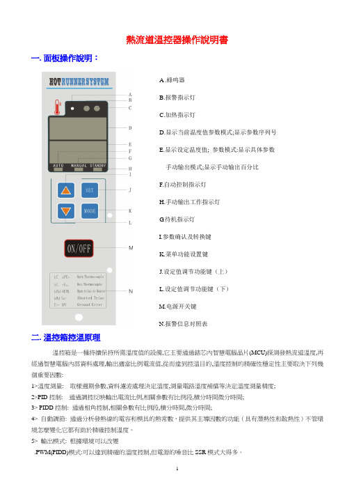
熱流道溫控器操作說明書一.面板操作說明:A .蜂鸣器B.报警指示灯C.加热指示灯D.显示当前温度值参数模式;显示参数序列号E.显示设定温度值; 参数模式:显示具体参数手动输出模式;显示手动输出百分比F.自动控制指示灯H.手动输出工作指示灯G.待机指示灯I.参数确认及转换键K.菜单功能设置键J.设定值调节功能键(上)L.设定值调节功能键(下)M.电源开关键N.报警信息对照表二.溫控箱控溫原理溫控箱是一種持續保持所需溫度值的設備,它主要通過錶芯內智慧電腦晶片(MCU)探測發熱流道溫度,再經過智慧電腦內部資料處理,輸出適當比例電流值,從而達到控溫目的,溫度控制的精確性穩定性主要取決下列幾個重要因數:1>溫度測量: 取樣週期參數,資料濾波處理決定溫度,測量電路溫度補償等決定溫度測量精度;2>PID控制: 通過調控反映輸出電流比例,相關參數有比例段,積分時間微分時間;3> PIDD控制: 通過相角控制,相關參數有比例段,積分時間,微分時間;4> 自動調節: 通過分析發熱線的電容和模具的熱常數,提供其主導因數的功能(具有潛熱性和散熱性)不管環境怎麼變化它都有助於精確控制溫度。
5> 輸出模式: 根據環境可以改變.PWM(PIDD)模式:可以達到精確的溫度控制,但電源的噪音比SSR模式大得多。
.SR(PID)模式:電流噪音小,但對特定溫度的控制能力比PWM模式差三.溫控箱錶芯規格.室內使用.電源輸入電壓:AC185V-245V,50/60HZ,15A.載荷:15A,100W-1650W;.輸出類型:PWM(移相脈寬調節).SSR(固態).感溫線類型:J或K型熱電偶.溫度控制範圍:50C-550C.溫度穩定性:+0.5%.溫度控制類型:FUZZY+PIDD人工智慧+移相控制.內部測量環路自動環境溫度補償.錶芯線電壓輸入保護功能.軟啟動消除因潮濕引起的模具漏電功能. F1,F2:250V-15A(特殊保險絲).F1A,F3:250-1A四.產品功能介紹1>採用FUZZY PIDD控制技術, 在沒有整定PID參數的情況下,它能自動適應任何發熱模型,極大提高了工作效率;2>380伏輸入保護, 避免由於電壓輸入錯誤造成控制器損壞;3>自動環境溫度線性補償,使該控制器溫度值更具有精確性;4>感應器錯誤監視:控制器能夠偵察到溫度感應器反向和溫度感應器開路,當感應器問題被偵察到時,控制器根據錯誤類型和控制器的模式進行動作;5>控制器內部測量環斷偵察(Loop Break Detection);6>加熱器電流監視;7>輸出中斷檢查(Output Interruption Check);8>漏電錯誤偵察電路(Ground Fault Detection Circuit);9>溫度偏離報警(Deviation Alarms);10>手動功率輸出模式;11>軟體鎖定功能;12>支援無碰傳輸;13>全面錯誤資訊指示輸出,使您輕鬆發現當前失效原因五.操作模式.1>自動模式: 正常的操作模式下,溫度可設定,能自動調節達到與設定溫度一致。
1、概述:ETC-60是适用于中、低温通风型制冷系统的温度控制器。
三路输出控制压缩机、风机及电气或热汽化霜;双传感器用于测量库温与蒸发器温度,NTC与PTC可互换;摄氏、华氏显示转换;显示分辨率可选择;三层菜单可避免用户不合理设置;支持各种数字量输入(门开关、外部报警、制冷/制热模式转换、压力开关保护等),并具备拷贝卡功能。
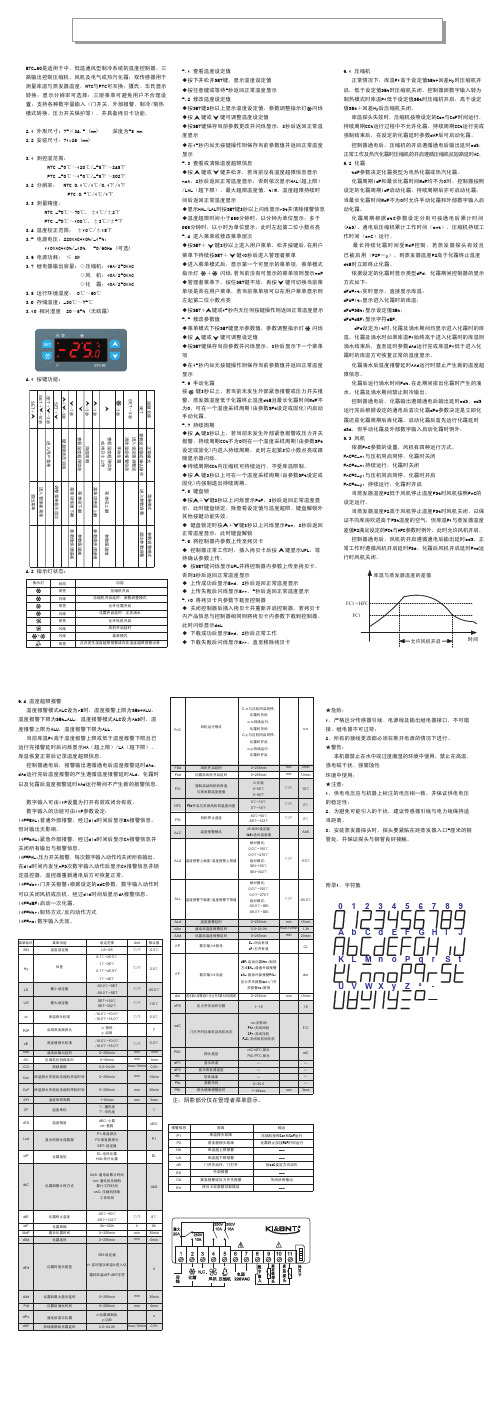
2、规格尺寸:2.1 外形尺寸: 75×34.5 (mm) 深度为58 mm2.2 安装尺寸:71x29 (mm)3、技术参数:3.1 测控温范围:NTC -50℃~120℃/-58℉~248℉PTC -50℃~150℃/-58℉~302℉3.2 分辨率: NTC 0.1℃/1℃/0.1℉/1℉PTC 0.5℃/1℃/1℉3.3 测量精度:NTC -50℃~70℃, ±1℃/±2℉PTC -50℃~100℃, ±3℃/±5℉3.4 温度校正范围: ±10℃/±18℉3.5 电源电压:220VAC+10%/-15%;110VAC+10%/-10%, 50/60Hz (可选)3.6 电源功耗: ≤ 3W3.7 继电器输出容量: ◇压缩机:16A/250VAC◇风 机:10A/250VAC◇化 霜:10A/250VAC3.8 运行环境温度: 0℃~60℃3.9 存储温度: -30℃~75℃3.10 相对湿度 20~85% (无结霜)4、控制器前面板:4.1 按键功能:4.2 指示灯状态:5、操作说明:5.1 查看温度设定值◆按下并松开SET键,显示温度设定值◆按任意键或等待5秒返回正常温度显示5.2 修改温度设定值◆按SET键3秒以上显示温度设定值,参数调整指示灯 闪烁◆按 键或 键可调整温度设定值◆按SET键保存当前参数更改并闪烁显示,3秒后返回正常温度显示◆在15秒内如无按键操作则保存当前参数值并返回正常温度显示5.3 查看或清除温度超限信息◆按 键或 键并松开,若当前没有温度超限信息显示noA,2秒后返回正常温度显示;否则依次显示HAL(超上限)/LAL(超下限)、最大超限温度值、tiM、温度超限持续时间后返回正常温度显示◆显示HAL/LAL时按SET键3秒以上闪烁显示rSt并清除报警信息◆温度超限时间小于999分钟时,以分钟为单位显示;多于999分钟时,以小时为单位显示,此时左起第二位小数点亮5.4 进入菜单或修改菜单层次◆按SET+ 键3秒以上进入用户菜单,松开按键后,在用户菜单下持续按SET+ 键10秒后进入管理者菜单◆进入菜单模式后,显示第一个可显示的菜单项,菜单模式指示灯 + 闪烁,若当前没有可显示的菜单项则显示noP◆管理者菜单下,按住SET键不放,再按 键可切换当前菜单项是否在用户菜单,若当前菜单项可以在用户菜单显示则左起第二位小数点亮◆按SET+ 键或15秒内无任何按键操作则返回正常温度显示5.5 修改参数值◆菜单模式下按SET键显示参数值,参数调整指示灯 闪烁◆按 键或 键可调整设定值◆按SET键保存当前参数并闪烁显示,3秒后显示下一个菜单项◆在15秒内如无按键操作则保存当前参数值并返回正常温度显示5.6 手动化霜按 键3秒以上,若当前未发生外部紧急报警或压力开关报警,蒸发器温度低于化霜终止温度dtE且最长化霜时间MdF不为0,可在一个温度采样周期(由参数SFt设定或固化)内启动手动化霜。
FTC200温度控制仪 用户手册■ 基本功能FTC200温度控制仪与油箱安装式温度传感器(FGW -100)配套使用,主要用于对无腐蚀性液态介质的温度进行测量、显示与控制等,也可向电气控制系统(如PLC 等)输出模拟信号。
特别适用于液压、润滑传动系统油液油温的测量与控制。
▲ 以℃或用户自定义显示当前测量温度 ▲ 四位LED 显示测量值▲ 四路开关量可根据当前温度、预设开关点、延滞、开启和关闭延时来进行切换 ▲ 0~10V 或4~20mA 标准模拟信号可根据用户要求进行切换 ▲ 可随时查看工作过程中最高温度▲ 可以锁定或隐藏基本菜单,以防止随意更改■ 薄膜键盘上的操作按键■ 启动界面接通电源后,先短暂显示“FTC ”字样,约2秒后显示当前实际测量温度。
注:1、在基本设置菜单中可以改变初始显示方式,这样接通电源后,先短暂显示“FTC ”字样,约2秒后显示相应设置值:SP1,SP2,SP3,SP4,MAX 。
2、若当前温度超过了正常范围,则无法显示实际值,此时显示屏会闪烁。
■ 开关量输出FTC200温度控制仪有四路开关量输出(继电器输出)。
每个继电器均可设置一个开关点、一个回复点或一个延滞。
当达到预设开关点时,相应的继电器切换动作,当温度降到回复点以下时,相应的继电器回复到初始状态。
■ 模拟量输出FTC200温度控制仪表可以输出一路4~20mA 或0~10V 标准模拟量信号(在基本设置菜单中可进行相应设置)。
■开关点设置如下图,按相应的键,显示开关点,回复点或延滞相应代码,如SP1,RSP1、HYS1等,2秒后显示相应设置,用“+”或“-”键来改变设置。
“S.P.1”-“S.P.4”=开关点1-4“HYS.1”-“HYS.4”=延滞1-4“R.S.P.1”-“R.S.P.4”=开关回复点1-4▲设置开关点▲设置延滞:只有当开关回复模式设置为“延滞”时才可进行设置。
▲设置回复点:只有当开关回复模式设置为“开关回复点”时才可进行设置。
Products Solutions Services TI01016T/09/EN/02.1371236165Technical InformationTC insertTPC200With ceramic isolatorFor installation in high temperature assembliesof TAF seriesThermocouple sensor types J, K, R, S, BApplication•Replaceable insert for installation inhigh temperature assemblies TAF11 and TAF16•Thermocouple sensors measuring range up to +1700°C (+3092 °F)Your benefits•Customized immersion length•Single or double measurement junction•Selection of different TC wire diametersTPC2002Endress+HauserFunction and system designMeasuring principleThermocouples are comparatively simple, robust temperature sensors which use the Seebeck effect for temperature measurement: If two electrical conductors made of different materials are connected at a point, a weak electrical voltage can be measured between the two open conductor ends if the conductors are subjected to a thermal gradient. This voltage is called thermoelectric voltage or electromotive force (emf.). Its magnitude depends on the type of conducting materials and the temperature difference between the "measuring point" (the junction of the two conductors) and the "cold junction" (the open conductor ends). Accordingly, thermocouples primarily only measuredifferences in temperature. The absolute temperature at the measuring point can be determined from these if the associated temperature at the cold junction is known or is measured separately and compensated for. The material combinations and associated thermoelectric voltage/temperature characteristics of the most common types of thermocouple are standardized in the IEC 60584 and ASTM E230/ANSI MC96.1 standards.Measuring range Performance characteristicsAccuracyPermissible deviation limits of thermoelectric voltages from standard characteristic for thermocouples as per IEC 60584 or ASTM E230/ANSI MC96.1:InputDesignationMeasuring range limitsThermocouples (TC)1) as per IEC 60584Type J (Fe-CuNi)Type K (NiCr-Ni)Type S (PtRh10-Pt)Type R (PtRh13-Pt)Type B (PtRh30-PtRh6)-210… +1200 °C (-346… +2192 °F), typical sensitivity ≈ 55 μV/K -270… +1372 °C (-454… +2502 °F), typical sensitivity ≈ 40 μV/K -50… +1768 °C (-58… +3214 °F), typical sensitivity ≈ 11 μV/K -50… +1768 °C (-58… +3214 °F), typical sensitivity ≈ 13 μV/K 0…+1820 °C (+32... + 3308 °F), typical sensitivity ≈ 9 μV/K1) Typical sensitivity above 0 °C (+32 °F)StandardTypeStandard tolerance Special tolerance IEC 60584ClassDeviationClass DeviationJ (Fe-CuNi)2±2.5 °C (-40...333 °C)±0.0075 |t|1) (333...750 °C)1 ±1.5 °C (-40...375 °C)±0.004 |t|1) (375...750 °C)K (NiCr-Ni)2±2.5 °C (-40...333 °C)±0.0075 |t|1) (333...1200 °C)1 ±1.5 °C (-40...375 °C)±0.004 |t|1) (375...1000 °C)R (PtRh13-Pt) and S (PtRh10-Pt)2±1.5 °C (0...600 °C)±0.0025 |t|1) (600...1600 °C)1±1 °C (0...1100 °C)±[1 + 0.003(|t|1)-1100)] (1100 °C...1600 °C)S (PtRh13-Pt)21B (PtRh30-PtRh6)2±1.5 °C or±0.0025 |t|1) (600...1700 °C)--1) |t| = Absolute temperature value in °CTPC200Endress+Hauser 3Calibration specificationsEndress+Hauser provides comparison temperature calibration from -80 to +1400 °C (-110 °F to 2552°F) based on the International Temperature Scale (ITS90). Calibrations are traceable tonational and international standards. The calibration report is referenced to the serial number of the insert.MaterialSheath materials.The temperatures for continuous operation specified in the following table are only intended asreference values for use of the various materials in air and without any significant compressive load. The maximum operation temperatures are reduced considerably in some cases where abnormal conditions such as high mechanical load occur or in aggressive media.Standard Type Standard toleranceSpecial toleranceASTM E230/ANSI MC96.1Deviation, the larger respective value appliesJ (Fe-CuNi)±2.2 K or ±0.0075 |t|1)(0...760 °C)±1.1 K or ±0.004 |t|1) (0...760 °C)K (NiCr-Ni)±2.2 K or ±0.02 |t|1) (-200 ... 0 °C)±2.2 K or ±0.0075 |t|1)(0...1260 °C)±1.1 K or ±0.004 |t|1) (0...1260 °C)R (PtRh13-Pt) and S (PtRh10-Pt)±1.5 K or ±0.0025 |t|1)(0...1480 °C)±0.6 K or ±0.001 |t|1)(0...1480 °C)S (PtRh13-Pt)B (PtRh30-PtRh6)±0.005 |t|1) (870...1700 °C)±0.0025 |t|1) (870...1700 °C)1)|t| = absolute temperature value in °CIn order to obtain the maximum tolerances in °F, the results in °C must be multiplied by a factor of 1.8.Temperature rangeMinimum insertion length IL in mm (in)-80 °C to -40 °C (-110 °F to -40 °F)200 (7.87)-40 °C to 0 °C (-40 °F to 32 °F)160 (6.3)0 °C to 250 °C (32 °F to 480 °F)120 (4.72)250 °C to 550 °C (480 °F to 1020 °F)300 (11.81)550 °C to 1400 °C (1020 °F to 2552 °F)450 (17.75)Material nameShort formRecommended max. temperature for continuous use in airPropertiesCeramic material types according to DIN VDE0335C6101500 °C (2732 °F)•Al 2O 3-content approx. 60 %, alkali-content 3 %•The most economic non porous ceramic material•Highly resistant to hydrogen fluoride, temperature shocks and mechanical influences, normally used for internal and external thermowells as well as insulators C7991800 °C (3272 °F)•Al 2O 3-content approx. 99.7 %•Can be used for both internal and external thermowells and insulators•Resistance to hydrogen fluoride gases and alkaline vapors, to oxydizing, reducing and neutral atmospheres as well as temperature changes•This material is very pure and has a very low porosity (gas tight) compared to all other types of ceramicsTPC2004Endress+HauserMechanical constructionDesign, dimensionsFig.1:All dimensions in mm (in).The measuring point of the thermocouple is located close to the tip of the insert. The operatingtemperature ranges (→ä2) and permissible deviation limits of the thermoelectric voltages from the standard characteristic (→ä2) vary according to the type of thermocouple used. The thermocouple wires are inserted in appropriate high-temperature-resistant ceramic isolators.ABMeasuring insert with TC type J or K,ceramic segment isolator and mounted terminal block (DIN B)Measuring insert with TC type R, S or B,with external ceramic sheath and mounted terminal block (DIN B)Lg X He Di Immersion length of the assemblies thermowell Additional length, see table below Insert length (He = Lg + X)Diameter insertInsert length He calculation rules (He = Lg + X) TPC200Material high temperature assembly Terminal head DIN B Terminal head DIN A TAF11 thermowell:•C610 + sleeve•Sinterized silicon carbide SIC + sleeve•Special silicon nitride ceramic SiN + sleeveHe = Lg + 15 mm (0.6 in)He = Lg + 5 mm (0.2 in)He = Lg + 10 mm (0.4 in)He = Lg + 30 mm (1.2 in)He = Lg + 20 mm (0.8 in)He = Lg + 25 mm (1.0 in)TAF16 thermowell:•NiCo special nickel/cobalt alloy (metal cap)•All metal thermowells, e. g. 310, 446, 316, etc.•Bar stock tip thermowells NiCo and INCOLOY800HT •Kanthal Super•SiN (special silicon nitride ceramic)•Kanthal AFHe = Lg + 5 mm (0.2 in)He = Lg + 15 mm (0.6 in)He = Lg + 10 mm (0.4 in)He = Lg + 10 mm (0.4 in)He = Lg + 10 mm (0.4 in)He = Lg + 10 mm (0.4 in)He = Lg + 20 mm (0.8 in)He = Lg + 30 mm (1.2 in)He = Lg + 25 mm (1.0 in)He = Lg + 25 mm (1.0 in)He = Lg + 25 mm (1.0 in)He = Lg + 25 mm (1.0 in)When configuring the high temperature assemblies of the TAF family the thermocouple wire diameter also needs to be defined. The higher the temperature the larger the wire diameter needs to be selected. A large wire diameter will also increase the lifetime of the sensor.TPC200Endress+Hauser5WeightDepending on length and diameter, e. g. 0.1 kg ( 3.53 oz) for Lg = 580 mm (22.8 in) and diameter 8 mm (0.3 in).WiringWiring diagramsThermocouple wire colorsType of insert Wire diameter in mm (in)Insert diameter in mm (in)1x K, 2x K, 1x J, 2x J 1.63 (0.06)8 (0.31)1x K, 2x K, 1x J, 2x J 2.3 (0.09)8 (0.31)1x K, 1x J 3.26 (0.13)12 (0.47), 14 (0.55)2x K, 2x J 3.26 (0.13)12 (0.47), 14 (0.55)1x S, 2x S0.35 (0.014) 6 (0.24)1x S, 2x S, 1x R, 2x R, 1x B, 2x B0.5 (0.02)6 (0.24)As per IEC 60584•Type J: black (+), white (-)•Type K: green (+), white (-)•Type B: grey (+), white (-)•Type R: orange (+), white (-)•Type S: orange (+), white (-)TPC2006Endress+HauserInstallation conditionsOrientationNo restrictions.Installation instructionsCertificates and approvalsCE MarkThe device meets the legal requirements of the EC directives if applicable. Endress+Hauser confirms that the device has been successfully tested by applying the CE mark.Other standards and guidelines•IEC 60584:Thermocouples •DIN EN 50446:Straight thermocouple assembly with metal or ceramic protection tube and accessories, including terminal headsTest report and calibrationThe "Factory calibration" is carried out according to an internal procedure in a laboratory ofEndress+Hauser accredited by the European Accreditation Organization (EA) to ISO/IEC 17025.A calibration which is performed according to EA guidelines (SIT/Accredia or DKD/DAkks calibration) may be requested separately. The calibration is performed on the replaceable insert of thethermometer. In the case of thermometers without a replaceable insert, the entire thermometer - from the process connection to the tip of the thermometer - is calibrated.Observe the insert length calculation rules. →ä4Fig.2: Insert installationThe TPC200 insert is mounted in high temperatureassemblies of the TAF1x series with a flat face terminal head as per DIN EN 50446.TPC200Endress+Hauser 7Ordering informationDetailed ordering information is available from the following sources:•In the Product Configurator on the Endress+Hauser website: È Select country È Instruments È Select device È Product page function: Configure this product•From your Endress+Hauser Sales Center:/worldwideDocumentationTechnical information:High temperature assembliesOmnigrad S TAF11, TAF12x, TAF16 (TI00251T/09/en)Product Configurator - the tool for individual product configuration:•Up-to-the-minute configuration data•Depending on the device: Direct input of measuring point-specific information such as measuring range or operating language •Automatic verification of exclusion criteria•Automatic creation of the order code and its breakdown in PDF or Excel output format •Ability to order directly in the Endress+Hauser Online Shop。