电气工程毕业设计外文资料翻译
- 格式:doc
- 大小:1.07 MB
- 文档页数:18

本科毕业设计(论文)外文资料翻译系别:电气工程系专业:建筑电气与智能化班级:姓名:学号: 2007318230外文出处:《Electricity》附件:1、外文原文;2、外文资料翻译译文。
weak electricity engineeringSystem functionThe in common use building weak electricity system mainly has a few kinds as follows: (1)The telephone corresponds by letter systemCarry out telephone(include three types of facsimile machines, can see a telephone...etc.) correspondence function The star type To rushes toward structure; Use 3 types(or above) don't shield a double to wring line, deliver the frequency of signal within the scope of audio frequency.(2)Area net system in calculator bureauIs a realization to transact to automate and various data delivers of network foundation The star type to rushes toward structure Use 5 types(or above) don't shield a double to wring line, deliver number signal, the baud rate can reach to a 100 mbs the s is above.(3)Music| broadcast systemThe loudspeaker passed to install on the spot(is like places, such as market, restaurant, guest room and hallway...etc.) broadcasts music, and can pass to transmit sound machine to carry on a broadcasting to the spot Many road total line structure Deliver is certainly pressed a 120 Vs by the power enlarger output's| the audio frequency signal of 120 Ωs with drive the spot loudspeaker phonation, deliver the line use copper Xin to insulate to lead line.(4)The cabled T.V. signal assigns systemEvenly assign the cabled T.V. signal to each customer inside the building to order ;Adopt branch and assign a machine to carry on a signal allotment, for letting up signal to lose to really reduce and make each customer order the request that the signal quality attains norm rules with , its cloth line is tree type structure, and order to distribute with the form of building and the customer of dissimilarity but dissimilarity Use 75 Ω radio frequency coaxial cable, deliver many road radio frequencies signal.(5)The public security supervises and controls systemThe camera passed to install on the spot, guard against theft equipment like carry on surveillance and excrescent circumstance to report to the police to each exit and entrance and some important places of building etc. ;The video frequency signal delivers to adopt star type structure, use video frequency coaxial cable ;Control delivering of signal to adopt total line structure, the use copper insulates a cable.(6)The fire fight reports to the police systemThe system is reported to the police by a fire and the fire fight is allied the broadcasting system, fire alarm moving system, fire fight to constitute towards speaking 3 parts like telephone system.A fire reports to the police and the fire fight is allied and move system to pass constitution in the building everywhere of a fire locator, hand move to report to the police device etc. to the spot the circumstance carry on a monitor, be have already reported to the police signal, according to receiving of signal, according to in advance setting of procedure, unite the homologous equipments spreads by control fire, its signal delivers to adopt total line structure of many roads, but for important fire fight equipments(if fire fight pump, spray to sprinkle a pump, is pressing breeze machine and line up smoke breeze machine etc.) of allied move to control delivering of signal, sometimes adopt star type structure, the delivering of signal uses copper to insulate a cable.(the product having asks use double to wring line)The fire fight broadcasting system is used for to direct the spot while taking place a fire a personnel safety evacuation, adopt total line structure of many roads, the signal delivers to use copper to insulate to lead line.(the system can and music broadcasting system suitable for use) The fire alarm is two kinds of structure towards speaking that the telephone system is used for in command of spot fire fighter to carry on extinguishing fire a work, adopt star type and total line type, the signal delivers uses to shield line.(7)The exit and entrance controls systemUse calculator, intelligence Carmen equipment, such as lock and card reader...etc., carry on constitution, surveillance, control and record etc. to each exit and entrance status, carry out unify a management to each exit and entrance of building, promise mansion safety, its Tuo rushes toward structure and delivers to lie quality because of product but difference.(8)The parking lot charge manages systemPass to install under the exit and entrance ground of respond coil, respond the discrepancy of vehicle, pass artificial half auto the full-automatic charge management system, carry out a charge and control the Qi of dynamoelectric railing to shut... The system cloth's line is only limited by the exit and entrance of car field in the mansion, each exit and entrance from one set controller control, the controller can independently work as well as manage a calculator allied net with place of honor, its cloth line structure and deliver to lie quality because of product but difference.(9)Building Yu from control systemThe various examination and performance spare part passed to connect with each other with the spot controller, to mansion inside outside of the work status of various equipments(is like air condition, to the catchment, lighting, is provided to go together with equipment, such as electricity and elevator...etc.) inside various environment parameter and building carry on examination, surveillance and control, and link through a calculator network each the spot controller, carry on reasonable allotment and management to the resources and the equipments in the building, attain a comfortable, convenient, economical and dependable purpose .So far, building Yu from control system didn't yet international standard, the correspondence adopted by the product of different factory house negotiates each not same, it the spot total line and control the of total line to rush toward structure and deliver to lie quality also dissimilarity The underneath will make simple introduction towards being wide spread accepted by the international society currently and Works technique and technique for adopting.Also have the television meeting the system, expand a system and cruise more in addition system and building Yu to speak system, three forms(water, electricity, annoy form) automatically and copy form system The weak electricity system that the building of different function needs to be established is each not same.3 systems are integratedIn the middle of physically working, the design should integrate 3 aspects: etc. to consider an integrated problem between the systems of each weak electricity from the network integration, function integration and software interface.3.1 networks are integratedThe network integrates mainly on-line come to consider from the cloth of each system, make the weak electricity system of different function able to work the platform is at an unified cloth line up, so, on the other hand easy to also make on the other hand each weak electricity system to the management of clothes line systems on the spot the decoration of equipments up have larger vivid.At in common use building weak electricity system in, the telephone corresponds by letter system and the function of area net in the calculator bureau system and the hardware equipments of the use each not same, but it the network rush toward the decoration principle that the structure, information orders homology, and can use homology of delivering and lying quality and connect a plug-in, so can synthesize two cloth lines of systems as a cloth linesystem Thus, two systems can be an exploitation, the information orders of the function can change with each other and make two systems all have larger vivid, this is also we say of synthesize cloth line system(PDS).Remaining as to it's is a few systems, in the comprehensive consideration technique and economic possibility, current product because of being rushed toward by system Tuo the structure, signal deliver to lie quality and double wring line to synthesize PDS towards delivering power signal of limiting etc., its cloth line system temporarily canning not returning But, along with the continuously developing of the number signal processing theory and application technique and calculator technique, and correspondence technique...etc., future PDS will definitely develop to become the cloth line that includes more different function weak electricity systems platform.3.2 functions are integratedThe function integration includes a following both side contents:(1) the function merge Main consideration will some on the function and hardware equipments up repeated of the system merge and make to merge the system of the empress before having merger all functions of each system, with decrease equipments redundancy, avoid repeated investment In the above-mentioned system, music broadcasting system and fire fight report to the police and allied move the fire fight within system broadcasting system and then can be a system to design, but the system has to satisfy the rules of 《the fire fight automatically reports to the police a system design norm (GBJ 50116-98)》.(2) the function repair with each other See from the function, each sub- systems in the building Yu automation all have its particular function and rule over scope and respectively and independently work at ordinary times, but while taking place some and special affairs, usually needing an of each system can be in conjunction with a work, the whole system carries out overall control and management the exaltation to the processing ability that bursts affairs, exaltation building of the intelligence turn degree Is concrete of allied move to respond to include a few systems as follows:The fire fight reports to the police system →music broadcasting system When occurrence fire fight reported to the police, correspond the public broadcasting system of floor will drive strong line of cut over into an urgent broadcasting of fire fight;The fire fight reports to the police system →the public security supervise and control system When occurrence fire fight reported to the police, the public security supervised and control system to automatically be like the shooting of camera of fire alarm close by district theappearance sliced to hold to lord surveillance in the public security center and laid equal stress on some to record these shooting of cameras to be like contents with provide whether the confirmation has fire alarm occurrence to analyze with the after the event trouble reason etc.; The fire fight reports to the police system →the exit and entrance control system While confirming to take place fire fight to report to the police exit and entrance's control the each control door(the control door of important core part can establish alone) having something to do with fire alarm part in the system should automatically be placed in to open status, for the purpose of internal personnel evacuate to withdraw to get into with fire fighter;The fire fight reports to the police system →the gara ge manage system The garage management system should control garage while confirming fire fight to report to the police occurrence at the first floor or the underground layer the gateway place in open status, so that the vehicle inside the garage quickly withdraw a fire field;(at this time garage relevant of the camera should be placed in a work and record image status)The fire fight reports to the police system →the speech correspond by letter system After the fire fight reports to the police the system auto confirmation fire fight to report to the police occurrence, immediately pass the speech in the mansion correspondence system reports to the police to the fire fight bureau and deliver concerning the information, report to the police to supervisor's section in the mansion at the same time;Building Yu from control system →the public security supervise and control system When building Yu from control system to have difference to report to the police or trouble, the public security supervision system can automatically will report to the police the shooting of camera of close by district to be like appearance to slice to hold to lord surveillance in the public security center and lay equal stress on some to record these shooting of cameras to be like contents to provide after the event analysis the reason etc.;The public security supervises and controls system →building Yu from control system When the public security system reports to the police, can unite elevator control system, the elevator doesn't stop to depend to report to the police a layer, or stop to depend a public security member appointed layer;The exit and entrance controls system →the public security supervise and control system When control door at not work when someone hold card into or take place illegal incursion the public security supervises and controls a system auto will get into of control door or report to the police a shooting of the camera of ordering the close by district to be like appearance toslice toward the public security center lord surveillance hold, lay equal stress on some to record these shooting of cameras to be like contents to check when it's necessary by providing; The garage manages system →the public security supervise and control system When the garage has vehicle discrepancy, the public security supervises and controls a system auto to be like the shooting of camera of garage door appearance to slice to hold to lord surveillance in the public security center and lay equal stress on some to record these shooting of cameras to be like contents to check when it's necessary by providing.In fact, the function between each system is integrated and allied to move to respond to have no one mode of unified or fix, can establish according to the effective demand.The function integrates a purpose just, in fact existing two kinds of modes, 1 kind is at each statures system on build up higher and first-degree management and control network, another is with building Yu from control system for center of integrated mode No matter choose which integrated mode, key techniques' all wanting to work out a correspondence problem between each system , while making sure a solution, must adopt theory forerunner and technique maturity and wide spread accept for industry and the correspondence adopting negotiate.The building Yu been widespread accepted by the international society currently from control correspondence agreement of realm, is provided heat by the United States and make cold regulate the association establishment of engineer with air, and become standard ANSI of of ASCII|ASHRAE Standard 135-1995), it matches ISO(international standardizing organization) OSI(open system with each other connect)7 F model, forgiving 5 kinds already mature network correspondence agreement, including correspondences such as ether net and Long Talk etc. agreement Among them, the ether net correspondence agreement is an OA system to widespread use of a kind of correspondence agreement, majority of network operate systems all support this correspondence agreement But the Works technique is the new generation that the United States' Echelon company develops the spot total line technique, its outstanding advantage is to support arbitrarily to rush toward structure and support variety's delivering to lie quality(include a double to wring line, electric power line, wireless electric wave, infrared ray, coaxial cable and fiber optic), and variety lie quality can mix to use in the same network, as a result consumedly simplified engineering construction and system to be finished after of change to set up, extension and maintenance work Therefore, building Yu according to standard from control system, can a little bit easily carry out at the its control total line class and the integration of OA system, again because it forgives of the correspondence negotiatesupport double to wring line and star type to rush toward structure, as a result can use PDS as its signal to deliver path.弱电工程弱电系统功能常用的建筑弱电系统主要有以下几种:(1) 电话通信系统实现电话(包括三类传真机、可视电话等)通信功能;星型拓扑结构;使用三类(或以上)非屏蔽双绞线,传输信号的频率在音频范围内。
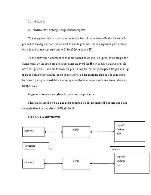
1、外文原文A: Fundamentals of Single-chip MicrocomputerTh e si ng le -c hi p m ic ro co mp ut er i s t he c ul mi na ti on of both t h e de ve lo pm en t of the dig it al com pu te r an d th e in te gr at ed c i rc ui t arg ua bl y t h e tow m os t s ig ni f ic an t i nv en ti on s o f t he 20th c e nt ur y [1].Th es e tow type s of arch it ec tu re are foun d in sin g le -ch i p m i cr oc om pu te r. Som e empl oy the spli t prog ra m/da ta me mo ry of the H a rv ar d ar ch it ect u re , sh ow n in Fig.3-5A -1, oth ers fo ll ow the p h il os op hy , wi del y ada pt ed for gen er al -p ur po se com pu te rs and m i cr op ro ce ss o r s, o f ma ki ng no log i ca l di st in ct ion be tw ee n p r og ra m and dat a me mo ry as in the Pr in ce to n arch ite c tu re , show n i n Fig.3-5A-2.In gen er al ter ms a sin gl e -chi p mic ro co mp ut er i sc h ar ac te ri zed b y t he i nc or po ra ti on of a ll t he un it s of a co mp uter i n to a sin gl e d ev i ce , as sho wn inFi g3-5A -3.Fig.3-5A-1 A Harvard typeFig.3-5A-2. A conventional Princeton computerFig3-5A-3. Principal features of a microcomputerRead only memory (ROM.R OM is usua ll y for the pe rm an ent,n o n-vo la ti le stor a ge of an app lic a ti on s pr og ra m .M an ym i cr oc om pu te rs and m are inte nd e d for high -v ol um e ap pl ic at ions a n d he nc e t h e eco n om ic al man uf act u re of th e de vic e s re qu ir es t h at t he cont en t s o f t he prog ra m me m or y be co mm it t ed perm a ne ntly d u ri ng the man ufa c tu re of ch ip s .Cl ea rl y, thi s im pl ie s a r i go ro us app ro ach to ROM cod e deve l op me nt sin ce cha ng es can not b e mad e afte r manu f a c tu re .Th is dev e lo pm en t proc ess may invo lv e e m ul at io n us in g aso ph is ti ca te d de ve lo pm en t sy ste m wit h a h a rd wa re emu la tio n cap ab il it y as w el l as the use o f po we rf ul s o ft wa re too ls.So me man uf act u re rs pro vi de add it io na l RO M opt i on s by i n cl ud in g in their ra n ge dev ic es wit h (or int en de d fo r use wit h u s er pro gr am ma ble me mo ry. Th e sim p le st of th es e is usu al ly d e vi ce whi ch can op er at e in a micro p ro ce ssor mod e by usi ng som e o f the inp ut /outp u t li ne s as an ad dr es s an d da ta b us fora c ce ss in g ex te rna l mem or y. Thi s t y pe of de vi ce can beh av ef u nc ti on al ly as th e sing le chip mi cr oc om pu te r from whi ch it is d e ri ve d al be it wit h re st ri ct ed I/O and a mod if ied ex te rn al c i rc ui t. The use of thes e d ev ic es is com mo n eve n in prod uc ti on c i rc ui ts wher e t he vo lu me does no tj us ti f y t h e d ev el o pm en t c osts o f c us to m o n -ch i p R OM [2];t he re c a n s ti ll bea s ignif i ca nt saving i n I /O and o th er c h ip s com pa re d to a conv en ti on al mi c ro pr oc es sor b a se d ci rc ui t. Mor e ex ac t re pl ace m en t fo r RO M dev i ce s ca n be o b ta in ed in th e fo rm of va ri an ts w it h 'p ig gy -b ack 'E P RO M(Er as ab le pro gr am ma bl e ROM s oc ke ts or dev ic e s with EPROM i n st ea d o f RO M 。
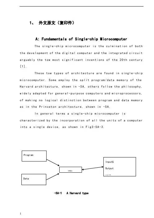
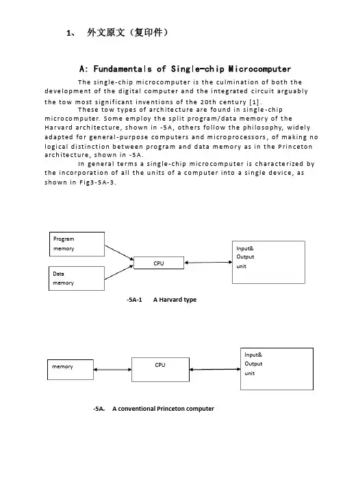
1、外文原文(复印件)A: Fundamentals of Single-chip MicrocomputerTh e si ng le-ch i p mi cr oc om pu ter is t he c ul mi nat i on o f bo th t h e d ev el op me nt o f th e d ig it al com p ut er an d t he int e gr at ed ci rc ui ta r gu ab ly th e t ow m os t s i gn if ic ant i nv en ti on s o f t h e 20t h c en tu ry[1].Th es e to w typ e s of a rc hi te ctu r e ar e fo un d i n s in gl e-ch ip m i cr oc om pu te r. So m e em pl oy t he sp l it p ro gr am/d ata me mo ry o f th e H a rv ar d ar ch it ect u re, sh ow n i n -5A, ot he rs fo ll ow th e ph i lo so ph y, w i de ly a da pt ed fo r g en er al-p ur pos e c om pu te rs an d m i cr op ro ce ss or s, o f m a ki ng no lo gi c al di st in ct io n b e tw ee n p ro gr am a n d da t a m em ory a s i n th e Pr in cet o n ar ch it ec tu re,sh ow n in-5A.In g en er al te r ms a s in gl e-chi p m ic ro co mp ut er i sc h ar ac te ri zed b y the i nc or po ra tio n of al l t he uni t s o f a co mp ut er i n to a s in gl e dev i ce, as s ho wn in Fi g3-5A-3.-5A-1 A Harvard type-5A. A conventional Princeton computerFig3-5A-3. Principal features of a microcomputerRead only memory (ROM).R OM i s u su al ly f or th e p er ma ne nt, n o n-vo la ti le s tor a ge o f an a pp lic a ti on s pr og ra m .M an ym i cr oc om pu te rs an d mi cr oc on tr ol le r s a re in t en de d fo r h ig h-v ol ume a p pl ic at io ns a nd h en ce t he e co nom i ca l ma nu fa ct ure of t he d ev ic es r e qu ir es t ha t the co nt en ts o f the pr og ra m me mo ry b e co mm it te dp e rm an en tl y d ur in g th e m an uf ac tu re o f c hi ps . Cl ear l y, th is im pl ie sa ri g or ou s a pp roa c h t o R OM co de d e ve lo pm en t s in ce c ha ng es ca nn otb e m ad e af te r man u fa ct ur e .T hi s d e ve lo pm en t pr oce s s ma y in vo lv e e m ul at io n us in g a s op hi st ic at ed deve lo pm en t sy st em w i th a ha rd wa re e m ul at io n ca pa bil i ty a s we ll a s th e u se of po we rf ul so ft wa re t oo ls.So me m an uf act u re rs p ro vi de ad d it io na l RO M opt i on s byi n cl ud in g i n th ei r ra ng e de vi ce s wi th (or i nt en de d fo r us e wi th) u s er pr og ra mm ab le m em or y. Th e s im p le st of th es e i s us ua ll y d ev ice w h ic h ca n op er ate in a m ic ro pr oce s so r mo de b y usi n g so me o f th e i n pu t/ou tp ut li ne s as a n ad dr es s an d da ta b us f or acc e ss in g e xt er na l m e mo ry. T hi s t ype o f d ev ic e c an b e ha ve fu nc ti on al l y a s t he si ng le c h ip mi cr oc om pu te r fr om wh ic h i t i s de ri ve d a lb eit w it h r es tr ic ted I/O an d a mo di fie d e xt er na l ci rcu i t. T he u se o f t h es e RO Ml es sd e vi ce s is c om mo n e ve n in p ro du ct io n c ir cu it s wh er e t he v ol um e do es n o t ju st if y th e d e ve lo pm en t co sts of c us to m on-ch i p RO M[2];t he re c a n st il l b e a si g ni fi ca nt s a vi ng in I/O a nd ot he r c hi ps co mp ar ed t o a c on ve nt io nal mi cr op ro ce ss or b as ed c ir cu it. M o re e xa ctr e pl ac em en t fo r RO M d ev ic es c an b e o bt ai ne d in t he f o rm o f va ri an ts w i th 'pi gg y-ba ck'EP RO M(Er as ab le p ro gr am ma bl e ROM)s oc ke ts o rd e vi ce s w it h EP ROM i ns te ad o f R OM 。
1、 外文原文(复印件)A: Fundamentals of Single-chip MicrocomputerT h e sin gle -ch ip mi c ro co m p u t e r is t h e cu lm in at io n of b ot h t h e d e ve lo p me nt of t h e d ig ita l co m p u t e r a n d t h e i nte g rated c ircu it a rgu ab l y t h e to w mo st s ign if i cant i nve nt i o n s of t h e 20t h c e nt u ry [1].T h ese to w t yp e s of arch ite ct u re are fo u n d in s in gle -ch ip m i cro co m p u te r. S o m e e mp l oy t h e sp l it p ro gra m /d at a m e m o r y of t h e H a r va rd arch ite ct u re , s h o wn in -5A , ot h e rs fo l lo w t h e p h i lo so p hy, wid e l y ad a p ted fo r ge n e ral -p u rp o se co m p u te rs an d m i cro p ro ce ss o rs , of m a kin g n o l o g i ca l d i st in ct i o n b et we e n p ro gra m an d d ata m e m o r y as in t h e P rin c eto n a rch ite ct u re , sh o wn in -5A.In ge n e ra l te r m s a s in g le -ch ip m ic ro co m p u t e r is ch a ra cte r ized b y t h e in co r p o rat io n of all t h e u n its of a co mp u te r into a s in gle d e vi ce , as s h o w n in F i g3-5A-3.-5A-1A Harvard type-5A. A conventional Princeton computerProgrammemory Datamemory CPU Input& Output unitmemoryCPU Input& Output unitResetInterruptsPowerFig3-5A-3. Principal features of a microcomputerRead only memory (ROM).RO M is u su a l l y fo r t h e p e r m an e nt , n o n -vo lat i le sto rage of an ap p l i cat io n s p ro g ram .M a ny m i c ro co m p u te rs a n d m i cro co nt ro l le rs are inte n d ed fo r h i gh -vo lu m e ap p l i cat io n s a n d h e n ce t h e e co n o m i cal man u fa c t u re of t h e d e vi ces re q u ires t h at t h e co nt e nts of t h e p ro gra m me mo r y b e co mm i ed p e r m a n e nt l y d u r in g t h e m a n u fa ct u re of c h ip s . C lea rl y, t h i s imp l ies a r i go ro u s ap p ro a ch to ROM co d e d e ve lo p m e nt s in ce ch an ges can n o t b e mad e af te r m an u fa ct u re .T h i s d e ve l o p m e nt p ro ces s m ay i nvo l ve e mu l at i o n u sin g a so p h ist icated d e ve lo p m e nt syste m wit h a h ard wa re e mu l at i o n capab i l it y as we ll as t h e u s e of p o we rf u l sof t war e to o l s.So m e m an u fa ct u re rs p ro vi d e ad d it i o n a l ROM o p t io n s b y in clu d in g in t h e i r ran ge d e v ic es w it h (o r inte n d ed fo r u s e wit h ) u se r p ro g ram m a b le m e mo r y. T h e s im p lest of t h e se i s u su a l l y d e v i ce wh i ch can o p e rat e in a m i cro p ro ce s so r mo d e b y u s in g s o m e of t h e in p u t /o u t p u t l in es as an ad d res s a n d d ata b u s fo r a cc es sin g exte rn a l m e m o r y. T h is t yp e o f d e vi ce can b e h ave f u n ct i o n al l y as t h e s in gle ch ip m i cro co m p u t e r f ro m wh i ch it i s d e ri ved a lb e it wit h re st r icted I/O an d a m o d if ied exte rn a l c ircu it. T h e u s e of t h e se RO M le ss d e vi ces i s co mmo n e ve n in p ro d u ct io n circu i ts wh e re t h e vo lu m e d o e s n ot ju st if y t h e d e ve lo p m e nt co sts of cu sto m o n -ch ip ROM [2];t h e re ca n st i ll b e a si gn if i cant sav in g in I/O an d o t h e r ch ip s co m pared to a External Timing components System clock Timer/ Counter Serial I/O Prarallel I/O RAM ROMCPUco nve nt io n al m i c ro p ro ces so r b ased circ u it. M o re exa ct re p l a ce m e nt fo rRO M d e v ice s can b e o b tain ed in t h e fo rm of va ria nts w it h 'p i g g y-b a c k'E P ROM(E rasab le p ro gramm ab le ROM )s o cket s o r d e v ice s w it h E P ROMin stead of ROM 。

毕业设计(论文)外文参考资料及译文译文题目:Kangle community Power Of Distribution in Yandu Of yancheng盐城市盐都区康乐小区配电设计学生姓名:学号: 0804110437 专业:电气工程及其自动化所在学院:机电工程学院指导教师:职称:讲师2012 年 3 月 3日Power Of community Distribution To DesignABSTRACT:The basic function of the electric power system is to transport the electric power towards customers. The l0kV electric distribution net is a key point that connects the power supply with the electricity using on the industry, business and daily-life. For the electric power, allcostumers expect to pay the lowest price for the highest reliability, but don't consider that it's self-contradictory in the co-existence of economy and reliable.To improve the reliability of the power supply network, we must increase the investment cost of the network construction But, if the cost that improve the reliability of the network construction, but the investment on this kind of construction would be worthless if the reducing loss is on the power-off is less than the increasing investment on improving the reliability .Thus we find out a balance point to make the most economic,between the investment and the loss by calculating the investment on power net and the loss brought from power-off.KEYWORDS:power supply and distribution, power distribution reliability,reactive compensation, load distributionThe revolution of electric power system has brought a new big round construction,which is pushing the greater revolution of electric power technique along with the application of new technique and advanced equipment. Especially, the combination of the information technique and electric power technique, to great ex- tent, has improved reliability on electric quality and electric supply. The technical development decreases the cost on electric construction and drives innovation of electric network. On the basis of national and internatio- nal advanced electric knowledge, the dissertation introduces the research hotspot for present electric power sy- etem as following.Firstly, This dissertation introduces the building condition of distribution automation(DA), and brings forward two typical construction modes on DA construction, integrative mode and fission mode .It emphasize the DA structure under the condition of the fission mode and presents the system configuration, the main station scheme, the feeder scheme, the optimized communication scheme etc., which is for DA research reference.Secondly, as for the (DA) trouble measurement, position, isolation and resume, This dissertation analyzes the changes of pressure and current for line problem, gets math equation by educing phase short circuit and problem position under the condition of single-phase and works out equation and several parameter s U& , s I& and e I& table on problem . It brings out optimized isolation and resume plan, realizes auto isolation and network reconstruction, reduces the power off range and time and improves the reliability of electric power supply through problem self- diagnoses and self-analysis. It also introduces software flow and use for problem judgement andsets a model on network reconstruction and computer flow.Thirdly, electricity system state is estimated to be one of the key techniques in DA realization. The dissertation recommends the resolvent of bad measurement data and structure mistake on the ground of describing state estimate way. It also advances a practical test and judging way on topology mistake in state estimate about bad data test and abnormity in state estimate as well as the problem and effect on bad data from state measure to state estimate .As for real time monitor and control problem, the dissertation introduces a new way to solve them by electricity break and exceptional analysis, and the way has been tested in Weifang DA.Fourthly, about the difficulty for building the model of load forecasting, big parameter scatter limit and something concerned, the dissertation introduces some parameters, eg. weather factor, date type and social environment effect based on analysis of routine load forecasting and means. It presents the way for electricity load forecasting founded on neural network(ANN),which has been tested it’s validity by example and made to be good practical effect.Fifthly, concerning the lack of concordant wave on preve nting concordant wave and non-power compensation and non-continuity on compensation, there is a topology structure of PWM main circuit and nonpower theory on active filter the waves technique and builds flat proof on the ground of Saber Designer and proves to be practical. Meanwhile, it analyzes and designs the way of non-power need of electric network tre- nds and decreasing line loss combined with DA, which have been tested its objective economic benefit throu- gh counting example.Sixthly, not only do the dissertation design a way founded on the magrginal electric price fitted to our present national electric power market with regards to future trends of electric power market in China and fair trade under the government surveillance, that is group competitio n in short-term trade under the way of grouped price and quantity harmony, but also puts forward combination arithmetic, math model of trading plan and safty economical restriction. It can solve the original contradiction between medium and long term contract price and short term competitive price with improvement on competitive percentage and cut down the unfair income difference of electric factory, at the same time, it can optimize the electric limit for all electric factories and reduce the total purchase charge of electric power from burthen curve of whole electric market network.The distribution network is an important link among the power system. Its neutral grounding mode and operation connects security and stability of the power system directly. At the same time, the problem about neutral grounding is associated with national conditions, natural environment, device fabrication and operation. For example, the activity situation of the thunder and lightning, insulating structure and the peripheral interference will influence the choice of neutral groundingmode Conversely, neutral grounding mode affects design, operation, debugs and developing. Generally in the system higher in grade in the voltage, the insulating expenses account for more sizable proportion at the total price of the equipment. It is very remarkable to bring the economic benefits by reducing the insulating level. Usually such system adopt the neutral directly grounding and adopt the autoreclosing to guarantee power supply reliability. On the contrary, the system which is lower in the voltage adopts neutral none grounding to raise power supply reliability. So it is an important subject to make use of new- type earth device to apply to the distribution network under considering the situation in such factors of various fields as power supply reliability, safety factor, over-voltage factor, the choice of relay protection, investment cost, etc.The main work of this paper is to research and choice the neutral grounding mode of the l0kV distribution network. The neutral grounding mode of the l0kV network mainly adopts none grounding, grounding by arc suppressing coil, grounding by reactance grounding and directly grounding. The best grounding mode is confirmed through the technology comparison. It can help the network run in safety and limit the earth electric arc by using auto-tracking compensate device and using the line protection with the detection of the sensitive small ground current. The paper introduces and analyzes the characteristic of all kind of grounding modes about l0kV network at first. With the comparison with technological and economy, the conclusion is drawn that the improved arc suppressing coil grounding mode shows a very big development potential.Then, this paper researches and introduces some operation characteristics of the arc suppressing coil grounding mode of the l0kV distribution network. And then the paper put emphasis on how to extinguish the earth electric arc effectively by utilizing the resonance principle. This paper combines the development of domestic and international technology and innovative achievement, and introduces the computer earth protection and autotracking compensate device. It proves that the improved arc suppressing coil grounding mode have better operation characteristics in power supply reliability, personal security, security of equipment and interference of communication. The application of the arc suppressing coil grounding mode is also researched in this paper.Finally, the paper summarizes this topic research. As a result of the domination of the arc suppressing coil grounding mode, it should be more popularized and applied in the distribution network in the future.The way of thinking, project and conclusions in this thesis have effect on the research to choose the neutral grounding mode not only in I0kV distribution network but also in other power system..The basic function of the electric power system is to transport the electric power towards customers. The l0kV electric distribution net is a key point that connects the power supply withthe electricity using on the industry, business and daily-life. For the electric power, all costumers expect to pay the lowest price for the highest reliability, but don't consider that it's self-contradictory in the co-existence of economy and reliable. To improve the reliability of the power supply network, we must increase the investment cost of the network con- struction But, if the cost that improve the reliability of the network construction, but the investment on this kind of construction would be worthless if the reducing loss is on the power-off is less than the increasing investment on improving the reliability .Thus we find out a balance point to make the most economic, between the investment and the loss by calculating the investment on power net and the loss brought from power-off. The thesis analyses on the economic and the reliable of the various line modes, according to the characteristics various line modes existed in the electric distribution net in foshan..First, the thesis introduces as the different line modes in the l0kV electric distribution net and in some foreign countries. Making it clear tow to conduct analyzing on the line mode of the electric distribution net, and telling us how important and necessary that analyses are.Second, it turns to the necessity of calculating the number of optimization subsection, elaborating how it influences on the economy and reliability. Then by building up the calculation mode of the number of optimization subsection it introduces different power supply projects on the different line modes in brief. Third, it carries on the calculation and analyses towards the reliability and economy of the different line modes of electric distribution net, describing drafts according by the calculation. Then it makes analysis and discussion on the number of optimization subsection.At last, the article make conclusion on the economy and reliability of different line modes, as well as, its application situation. Accordion to the actual circumstance, the thesis puts forward the beneficial suggestion on the programming and construction of the l0kV electric distribution net in all areas in foshan. Providing the basic theories and beneficial guideline for the programming design of the lOkV electric distribution net and building up a solid net, reasonable layout, qualified safe and efficiently-worked electric distribution net.References[1] Wencheng Su. Factories power supply [M]. Machinery Industry Publishing House. 1999.9[2] Jiecai Liu. Factories power supply design guidance [M]. Machinery Industry Publishing House.1999.12[3] Power supply and distribution system design specifications[S].China plans Press. 1996[4] Low-voltage distribution design specifications [S].China plans Press.1996.6译文:小区配电设计摘要:电力系统的基本功能是向用户输送电能。
本科毕业设计(论文)中英文对照翻译院(系部)电气工程与自动化学院专业名称电气工程及其自动化年级班级03级2班学生姓名指导老师电力系统1 电力的技术特点电力具有独特的技术特点,这使得电力工业具有独特的行业特点。
1.无形性。
用户不能用人体感官直接察觉千瓦时的用电量。
2.质量。
供电质量可由供电连续性或供电可靠性、在标准电压等级下的电压均等性、交流电压频率的正确不变性来度量。
3.电力的贮存。
与大多数行业不同,电力部门必须随时根据用电的需求生产出电力来,因为电能无法贮存。
4.对供电负责。
电由电力部门输送到用户,因此必须对安全、可靠供电负责。
5.对公众的安全。
电力部门须对公众及其技术人员提供稳妥的保护。
2 电力系统的规划预期到电力部门的供电负荷将持续增长,电力系统的容量也持续增大。
远期规划主要是保证这种扩建在技术上是适宜的,在造价上是合理的,与增长模式是相符的。
远期规划者碰到的困难包括:不同地域和不同时间负荷增长的不确定性、新发明新技术发展的可能性。
优异的系统规划要努力做到全系统设计的最优化,而不能为了系统某部分造价的最小化而不顾其它部分的影响。
近年来,已经强调了规划和运行的经济性。
现在则越来越强调可靠性和环境方面的因素。
在作出规划前,须要仔细考虑许多因素:(1)设备的决策具有远期效应,这需要15—25年的预期和研究。
(2)有许多发电途径可选择:核电、基荷火电、中等规模燃气轮机发电或水电,以及大型、中型、小型电厂和各种形式的蓄能。
(3)有多种送电途径可选择,例如由交流或直流,架空线或地下电缆送电并有各种电压等级。
(4)规划决策受负荷管理技术和负荷模式的影响。
(5)有关因素存在不确定性。
如将来燃料价格货币的利率资金的来源设备的强迫停运率新技术环境的要求。
3 电力分配3.1 最初的分配系统发电厂和最后的各支路之间的分配线路叫做最初的分配系统。
在这两个电力系统之间传输有多种方法. 其中最常见的两种方法是辐射式和环绕式。
电气工程的外文文献(及翻译)文献一:Electric power consumption prediction model based on grey theory optimized by genetic algorithms本文介绍了一种基于混合灰色理论与遗传算法优化的电力消耗预测模型。
该模型使用时间序列数据来建立模型,并使用灰色理论来解决数据的不确定性问题。
通过遗传算法的优化,模型能够更好地预测电力消耗,并取得了优异的预测结果。
此模型可以在大规模电力网络中使用,并具有较高的可行性和可靠性。
文献二:Intelligent control for energy-efficient operation of electric motors本文研究了一种智能控制方法,用于电动机的节能运行。
该方法提供了一种更高效的控制策略,使电动机能够在不同负载条件下以较低的功率运行。
该智能控制使用模糊逻辑方法来确定最佳的控制参数,并使用遗传算法来优化参数。
实验结果表明,该智能控制方法可以显著降低电动机的能耗,节省电能。
文献三:Fault diagnosis system for power transformers based on dissolved gas analysis本文介绍了一种基于溶解气体分析的电力变压器故障诊断系统。
通过对变压器油中的气体样品进行分析,可以检测和诊断变压器内部存在的故障类型。
该系统使用人工神经网络模型来对气体分析数据进行处理和分类。
实验结果表明,该系统可以准确地检测和诊断变压器的故障,并有助于实现有效的维护和管理。
文献四:Power quality improvement using series active filter based on iterative learning control technique本文研究了一种基于迭代研究控制技术的串联有源滤波器用于电能质量改善的方法。
毕业设计(论文)外文文献翻译文献、资料中文题目:AT89S52单片机应用文献、资料英文题目: AT89S52 MCU Applications文献、资料来源:文献、资料发表(出版)日期:院(部):专业:电气工程及其自动化班级:姓名:学号:指导教师:翻译日期: 2017.02.14本科毕业设计(论文)AT89S52单片机应用中英文翻译专业名称:电气工程及其自动化年级班级:学生姓名:指导老师:AT89S52 MCU ApplicationsFunction Characteristic DescriptionThe AT89S52 is a low-power, high-performance CMOS 8-bit microcontroller with 8K bytes of in-syste m programmable Flash memory. The device is manufactured using Atmel’s high-density nonvolatile memory technology and is compatible with the indus-try-standard 80C51 instruction set and pinout. The on-chip Flash allows the program memory to be reprogrammed in-system or by a conventional nonvolatile memory pro-grammer. By combining a versatile 8-bit CPU with in-system programmable Flash on a monolithic chip, the Atmel AT89S52 is a powerful microcontroller which provides a highly-flexible and cost-effective solution to many embedded control applications.The AT89S52 provides the following standard features: 8K bytes of Flash, 256 bytes of RAM, 32 I/O lines, Watchdog timer, two data pointers, three 16-bit timer/counters, a six-vector two-level interrupt architecture, a full duplex serial port, on-chip oscillator, and clock circuitry. In addition, the AT89S52 is designed with static logic for operation down to zero frequency and supports two software selectable power saving modes. The Idle Mode stops the CPU while allowing the RAM, timer/counters, serial port, and interrupt system to continue functioning. The Power-down mode saves the RAM con-tents but freezes the oscillator, disabling all other chip functions until the next interrupt or hardware reset.Pin DescriptionVCC :Supply voltage.GND :Ground.Port 0:Port 0 is an 8-bit open drain bidirectional I/O port. As an output port, each pin can sink eight TTL inputs. When 1s are written to port 0 pins, the pins can be used as high-impedance inputs. Port 0 can also be configured to be the multiplexed low-order address/data bus during accesses to external program and data memory. In this mode, P0 has internal pull-ups. Port 0 also receives the code bytes during Flash programming and outputs the code bytes dur-ing program verification. External pull-ups are required during program verification.Port 1:Port 1 is an 8-bit bidirectional I/O port with internal pull-ups. The Port 1 outputbuffers can sink/source four TTL inputs. When 1s are written to Port 1 pins, they are pulled high by the inter-nal pull-ups and can be used as inputs. As inputs, Port 1 pins that are externally being pulled low will source current (IIL) because of the internal pull-ups. In addition, P1.0 and P1.1 can be configured to be the timer/counter 2 external count input (P1.0/T2) and the timer/counter 2 trigger input (P1.1/T2EX), respectively, as shown in the follow-ing table 1. Port 1 also receives the low-order address bytes during Flash programming and verification.Port 2:Port 2 is an 8-bit bidirectional I/O port with internal pull-ups. The Port 2 output buffers can sink/source four TTL inputs. When 1s are written to Port 2 pins, they are pulled high by the inter-nal pull-ups and can be used as inputs. As inputs, Port 2 pins that are externally being pulled low will source current (IIL) because of the internal pull-ups. Port 2 emits the high-order address byte during fetches from external program memory and dur-ing accesses to external data memory that use 16-bit addresses (MOVX @ DPTR). In this application, Port 2 uses strong internal pull-ups when emitting 1s. During accesses to external data memory that use 8-bit addresses (MOVX @ RI), Port 2 emits the contents of the P2 Special Function Register. Port 2 also receives the high-order address bits and some control signals during Flash program-ming and verification.Port 3:Port 3 is an 8-bit bidirectional I/O port with internal pull-ups. The Port 3 output buffers can sink/source four TTL inputs. When 1s are written to Port 3 pins, they are pulled high by the inter-nal pull-ups and can be used as inputs. As inputs, Port 3 pins that areexternally being pulled low will source current (IIL) because of the pull-ups. Port 3 receives some control signals for Flash programming and verification. Port 3 also serves the functions of various special features of the AT89S52, as shown in the fol-lowing table 2.RST:Reset input. A high on this pin for two machine cycles while the oscillator is running resets the device. This pin drives high for 98 oscillator periods after the Watchdog times out. The DISRTO bit in SFR AUXR (address 8EH) can be used to disable this feature. In the default state of bit DISRTO, the RESET HIGH out feature is enabled.ALE/PROG:Address Latch Enable (ALE) is an output pulse for latching the low byte of the address during accesses to external memory. This pin is also the program pulse input (PROG) during Flash programming. In normal operation, ALE is emitted at a constant rate of 1/6 the oscillator frequency and may be used for external timing or clocking purposes. Note, however, that one ALE pulse is skipped dur-ing each access to external data memory. If desired, ALE operation can be disabled by setting bit 0 of SFR location 8EH. With the bit set, ALE is active only during a MOVX or MOVC instruction. Otherwise, the pin is weakly pulled high. Setting the ALE-disable bit has no effect if the microcontroller is in external execution mode.PSEN:Program Store Enable (PSEN) is the read strobe to external program memory. When the AT89S52 is executing code from external program memory, PSEN is activated twice each machine cycle, except that two PSEN activations are skipped during eachaccess to exter-nal data memory.EA/VPP:External Access Enable. EA must be strapped to GND in order to enable the device to fetch code from external program memory locations starting at 0000H up to FFFFH. Note, however, that if lock bit 1 is programmed, EA will be internally latched on reset. EA should be strapped to VCC for internal program executions. This pin also receives the 12-volt programming enable voltage (VPP) during Flash programming.XTAL1:Input to the inverting oscillator amplifier and input to the internal clock operating circuit.XTAL2:Output from the inverting oscillator amplifier.Program MemoryIf the EA pin is connected to GND, all program fetches are directed to external memory. On the AT89S52, if EA is connected to VCC, program fetches to addresses 0000H through 1FFFH are directed to internal memory and fetches to addresses 2000H through FFFFH are to external memory.Data MemoryThe AT89S52 implements 256 bytes of on-chip RAM. The upper 128 bytes occupy a parallel address space to the Special Function Registers. This means that the upper 128 bytes have the same addresses as the SFR space but are physically separate from SFR space. When an instruction accesses an internal location above address 7FH, the address mode used in the instruction specifies whether the CPU accesses the upper 128 bytes of RAM or the SFR space. Instructions which use direct addressing access the SFR space. For example, the following direct addressing instruction accesses the SFR at location 0A0H (which is P2). MOV 0A0H, #data. Instructions that use indirect addressing access the upper 128 bytes of RAM. For example, the following indirect addressing instruction, where R0 contains 0A0H, accesses the data byte at address 0A0H, rather than P2 (whose address is 0A0H).MOV @R0, #data. Note that stack operations are examples of indirect addressing, so the upper 128 bytes of data RAM are available as stack space.。
毕业设计外文资料翻译Graduation design foreign language translation学院:电气工程与自动化学院专业班级:电子信息科学与技术三班学生姓名:学号:指导教师:外文资料:Microcomputer SystemsElectronic systems are used for handing information in the most general sense; this information may be telephone conversation, instrument read or a company‟s accounts, but in each case the same main type of operation are involved: the processing, storage and transmission of information. in conventional electronic design these operations are combined at the function level; for example a counter, whether electronic or mechanical, stores the current and increments it by one as required. A system such as an electronic clock which employs counters has its storage and processing capabilities spread throughout the system because each counter is able to store and process numbers.Present day microprocessor based systems depart from this conventional approach by separating the three functions of processing, storage, and transmission into different section of the system. This partitioning into three main functions was devised by V on Neumann during the 1940s, and was not conceived especially for microcomputers. Almost every computer ever made has been designed with this structure, and despite the enormous range in their physical forms, they have all been of essentially the same basic design.In a microprocessor based system the processing will be performed in the microprocessor itself. The storage will be by means of memory circuits and the communication of information into and out of the system will be by means of special input/output(I/O) circuits. It would be impossible to identify a particular piece of hardware which performed the counting in a microprocessor based clock because the time would be stored in the memory and incremented at regular intervals but the microprocessor. However, the software which defined the system‟s behavior would contain sections th at performed as counters. The apparently rather abstract approach to the architecture of the microprocessor and its associated circuits allows it to be very flexible in use, since the system is defined almost entirely software. The design process is largely one of software engineering, and the similar problems of construction and maintenance which occur inconventional engineering are encountered when producing software.The figure1-1 illustrates how these three sections within a microcomputer are connected in terms of the communication of information within the machine. The system is controlled by the microprocessor which supervises the transfer of information between itself and the memory and input/output sections. The external connections relate to the rest (that is, the non-computer part) of the engineering system.Fig.1-1 Three Sections of a Typical Microcomputer Although only one storage section has been shown in the diagram, in practice two distinct types of memory RAM and ROM are used. In each case, the word …memory‟ is rather inappropriate since a computers memory is more like a filing cabinet in concept; information is stored in a set of numbered …boxes‟ and it is referenced by the serial number of the …box‟ in question.Microcomputers use RAM (Random Access Memory) into which data can be written and from which data can be read again when needed. This data can be read back from the memory in any sequence desired, and not necessarily the same order in which it was written, hence the expres sion …random‟ access memory. Another type of ROM (Read Only Memory) is used to hold fixed patterns of information which cannot be affected by the microprocessor; these patterns are not lost when power is removed and are normally used to hold the program which defines the behavior of a microprocessor based system. ROMs can be read like RAMs, but unlike RAMs they cannot be used to store variable information. Some ROMs have their data patterns put in during manufacture, while others are programmable by the user by means of special equipment and are called programmable ROMs. The widely used programmable ROMs are erasable by means of special ultraviolet lamps and are referred to as EPROMs, short for Erasable Programmable Read Only Memories. Other new types of device can be erased electrically without the need for ultraviolet light, which are called Electrically Erasable Programmable Read OnlyMemories, EEPROMs.The microprocessor processes data under the control of the program, controlling the flow of information to and from memory and input/output devices. Some input/output devices are general-purpose types while others are designed for controlling special hardware such as disc drives or controlling information transmission to other computers. Most types of I/O devices are programmable to some extent, allowing different modes of operation, while some actually contain special-purpose microprocessors to permit quite complex operations to be carried out without directly involving the main microprocessor.The microprocessor processes data under the control of the program, controlling the flow of information to and from memory and input/output devices. Some input/output devices are general-purpose types while others are designed for controlling special hardware such as disc drives or controlling information transmission to other computers. Most types of I/O devices are programmable to some extent, allowing different modes of operation, while some actually contain special-purpose microprocessors to permit quite complex operations to be carried out without directly involving the main microprocessor.The microprocessor , memory and input/output circuit may all be contained on the same integrated circuit provided that the application does not require too much program or data storage . This is usually the case in low-cost application such as the controllers used in microwave ovens and automatic washing machines . The use of single package allows considerable cost savings to e made when articles are manufactured in large quantities . As technology develops , more and more powerful processors and larger and larger amounts of memory are being incorporated into single chip microcomputers with resulting saving in assembly costs in the final products . For the foreseeable future , however , it will continue to be necessary to interconnect a number of integrated circuits to make a microcomputer whenever larger amounts of storage or input/output are required.Another major engineering application of microcomputers is in process control. Here the presence of the microcomputer is usually more apparent to the user because provision is normally made for programming the microcomputer for the particular application. In process control applications the benefits lf fitting the entire system on to single chip are usually outweighed by the high design cost involved, because this sort lf equipment is produced in smaller quantities. Moreover, process controllers are usually more complicatedso that it is more difficult to make them as single integrated circuits. Two approaches are possible; the controller can be implemented as a general-purpose microcomputer rather like a more robust version lf a hobby computer, or as a …packaged‟ system, signed for replacing controllers based on older technologies such as electromagnetic relays. In the former case the system would probably be programmed in conventional programming languages such as the ones to9 be introduced later, while in the other case a special-purpose language might be used, for example one which allowed the function of the controller to be described in terms of relay interconnections, In either case programs can be stored in RAM, which allows them to be altered to suit changes in application, but this makes the overall system vulnerable to loss lf power unless batteries are used to ensure continuity of supply. Alternatively programs can be stored in ROM, in which case they virtually become part of the electronic …hardware‟ and are often referred to as firmware. More sophisticated process controllers require minicomputers for their implementation, although the use lf large scale integrated circuits …the distinction between mini and microcomputers, Products and process controllers of various kinds represent the majority of present-day micro computer applications, the exact figures depending on one‟s interpretation of the word …product‟. Virtually all engineering and scientific uses of microcomputers can be assigned to one or other of these categories. But in the system we most study Pressure and Pressure Transmitters. Pressure arises when a force is applied over an area. Provided the force is one Newton and uniformly over the area of one square meters, the pressure has been designated one Pascal. Pressure is a universal processing condition. It is also a condition of life on the planet: we live at the bottom of an atmospheric ocean that extends upward for many miles. This mass of air has weight, and this weight pressing downward causes atmospheric pressure. Water, a fundamental necessity of life, is supplied to most of us under pressure. In the typical process plant, pressure influences boiling point temperatures, condensing point temperatures, process efficiency, costs, and other important factors. The measurement and control of pressure or lack of it-vacuum-in the typical process plant is critical.The working instruments in the plant usually include simple pressure gauges, precision recorders and indicators, and pneumatic and electronic pressure transmitters. A pressure transmitter makes a pressure measurement and generates either a pneumatic orelectrical signal output that is proportional to the pressure being sensed.In the process plant, it is impractical to locate the control instruments out in the place near the process. It is also true that most measurements are not easily transmitted from some remote location. Pressure measurement is an exception, but if a high pressure of some dangerous chemical is to be indicated or recorded several hundred feet from the point of measurement, a hazard may be from the pressure or from the chemical carried.To eliminate this problem, a signal transmission system was developed. This system is usually either pneumatic or electrical. And control instruments in one location. This makes it practical for a minimum number of operators to run the plant efficiently.When a pneumatic transmission system is employed, the measurement signal is converted into pneumatic signal by the transmitter scaled from 0 to 100 percent of the measurement value. This transmitter is mounted close to the point of measurement in the process. The transmitter output-air pressure for a pneumatic transmitter-is piped to the recording or control instrument. The standard output range for a pneumatic transmitter is 20 to 100kPa, which is almost universally used.When an electronic pressure transmitter is used, the pressure is converted to electrical signal that may be current or voltage. Its standard range is from 4 to 20mA DC for current signal or from 1 to 5V DC for voltage signal. Nowadays, another type of electrical signal, which is becoming common, is the digital or discrete signal. The use of instruments and control systems based on computer or forcing increased use of this type of signal.Sometimes it is important for analysis to obtain the parameters that describe the sensor/transmitter behavior. The gain is fairly simple to obtain once the span is known. Consider an electronic pressure transmitter with a range of 0~600kPa.The gain isdefined as the change in output divided by the change in input. In this case, the output is electrical signal (4~20mA DC) and the input is process pressure (0~600kPa). Thus the gain. Beside we must measure Temperature Temperature measurement is important in industrial control, as direct indications of system or product state and as indirect indications of such factors as reaction rates, energy flow, turbine efficiency, and lubricant quality. Present temperature scales have been in use for about 200 years, the earliestkPamA kPa mA kPa kPa mA mA Kr 027.0600160600420==--=instruments were based on the thermal expansion of gases and liquids. Such filled systems are still employed, although many other types of instruments are available. Representative temperature sensors include: filled thermal systems, liquid-in-glass thermometers, thermocouples, resistance temperature detectors, thermostats, bimetallic devices, optical and radiation pyrometers and temperature-sensitive paints.Advantages of electrical systems include high accuracy and sensitivity, practicality of switching or scanning several measurements points, larger distances possible between measuring elements and controllers, replacement of components(rather than complete system), fast response, and ability to measure higher temperature. Among the electrical temperature sensors, thermocouples and resistance temperature detectors are most widely used.DescriptionThe AT89C51 is a low-power, high-performance CMOS 8-bit microcomputer with 4K bytes of Flash programmable and erasable read only memory (PEROM). The device is manufactured using Atmel‟s high-density nonvolatile memory technology and is compatible with the industry-standard MCS-51 instruction set and pinout. The on-chip Flash allows the program memory to be reprogrammed in-system or by a conventional nonvolatile memory programmer. By combining a versatile 8-bit CPU with Flash on a monolithic chip, the Atmel AT89C51 is a powerful microcomputer which provides a highly-flexible and cost-effective solution to many embedded control applications. Function characteristicThe AT89C51 provides the following standard features: 4K bytes of Flash, 128 bytes of RAM, 32 I/O lines, two 16-bit timer/counters, a five vector two-level interrupt architecture, a full duplex serial port, on-chip oscillator and clock circuitry. In addition, the AT89C51 is designed with static logic for operation down to zero frequency and supports two software selectable power saving modes. The Idle Mode stops the CPU while allowing the RAM, timer/counters, serial port and interrupt system to continue functioning. The Power-down Mode saves the RAM contents but freezes the oscillator disabling all other chip functions until the next hardware reset.Pin DescriptionVCC:Supply voltage.GND:Ground.Port 0:Port 0 is an 8-bit open-drain bi-directional I/O port. As an output port, each pin can sink eight TTL inputs. When 1s are written to port 0 pins, the pins can be used as highimpedance inputs.Port 0 may also be configured to be the multiplexed loworder address/data bus during accesses to external program and data memory. In this mode P0 has internal pullups.Port 0 also receives the code bytes during Flash programming,and outputs the code bytes during programverification. External pullups are required during programverification.Port 1Port 1 is an 8-bit bi-directional I/O port with internal pullups.The Port 1 output buffers can sink/source four TTL inputs.When 1s are written to Port 1 pins they are pulled high by the internal pullups and can be used as inputs. As inputs,Port 1 pins that are externally being pulled low will source current (IIL) because of the internal pullups.Port 1 also receives the low-order address bytes during Flash programming and verification.Port 2Port 2 is an 8-bit bi-directional I/O port with internal pullups.The Port 2 output buffers can sink/source four TTL inputs.When 1s are written to Port 2 pins they are pulled high by the internal pullups and can be used as inputs. As inputs,Port 2 pins that are externally being pulled low will source current, because of the internal pullups.Port 2 emits the high-order address byte during fetches from external program memory and during accesses to external data memory that use 16-bit addresses. In this application, it uses strong internal pullupswhen emitting 1s. During accesses to external data memory that use 8-bit addresses, Port 2 emits the contents of the P2 Special Function Register.Port 2 also receives the high-order address bits and some control signals during Flash programming and verification.Port 3Port 3 is an 8-bit bi-directional I/O port with internal pullups.The Port 3 output buffers can sink/source four TTL inputs.When 1s are written to Port 3 pins they are pulled high by the internal pullups and can be used as inputs. As inputs,Port 3 pins that are externally being pulled low will source current (IIL) because of the pullups.Port 3 also serves the functionsof various special features of the AT89C51 as listed below:Port 3 also receives some control signals for Flash programming and verification.RSTReset input. A high on this pin for two machine cycles while the oscillator is running resets the device.ALE/PROGAddress Latch Enable output pulse for latching the low byte of the address during accesses to external memory. This pin is also the program pulse input (PROG) during Flash programming.In normal operation ALE is emitted at a constant rate of 1/6 the oscillator frequency, and may be used for external timing or clocking purposes. Note, however, that one ALE pulse is skipped during each access to external Data Memory.If desired, ALE operation can be disabled by setting bit 0 of SFR location 8EH. With the bit set, ALE is active only during a MOVX or MOVC instruction. Otherwise, the pin is weakly pulled high. Setting the ALE-disable bit has no effect if the microcontroller is in external execution mode.PSENProgram Store Enable is the read strobe to external program memory.When the AT89C51 is executing code from external program memory, PSEN is activated twice each machine cycle, except that two PSEN activations are skipped during each access to external data memory.EA/VPPExternal Access Enable. EA must be strapped to GND in order to enable the device to fetch code from external program memory locations starting at 0000H up to FFFFH. Note, however, that if lock bit 1 is programmed, EA will be internally latched on reset.EA should be strapped to VCC for internal program executions.This pin also receives the 12-volt programming enable voltage(VPP) during Flash programming, for parts that require12-volt VPP.XTAL1Input to the inverting oscillator amplifier and input to the internal clock operating circuit. XTAL2Output from the inverting oscillator amplifier.Oscillator CharacteristicsXTAL1 and XTAL2 are the input and output, respectively,of an inverting amplifier which can be configured for use as an on-chip oscillator, as shown in Figure 1.Either a quartz crystal or ceramic resonator may be used. To drive the device from an external clock source, XTAL2 should be left unconnected while XTAL1 is driven as shown in Figure 2.There are no requirements on the duty cycle of the external clock signal, since the input to the internal clocking circuitry is through a divide-by-two flip-flop, but minimum and maximum voltage high and low time specifications must be observed.中文翻译:微型计算机控制系统(单片机控制系统)广义地说,微型计算机控制系统(单片机控制系统)是用于处理信息的,这种被用于处理的信息可以是电话交谈,也可以是仪器的读数或者是一个企业的帐户,但是各种情况下都涉及到相同的主要操作:信息的处理、信息的存储和信息的传递。

毕业设计(论文)外文参考资料及译文译文题目:洗衣机学生姓名:宋峰学号: 0821113516 专业:电气工程及其自动化所在学院:龙蟠学院指导教师:杭阿芳职称:讲师年月日Washing machinesHousehold washing machine from invention to now has experienced more than a century, through the following stages of development:The world's first washing machine is the United States in 1874 by Bill Blackstone ( Bill. Blackstone ) successfully developed. Around 1910, a first horizontal shaft drum type electric washing machine, marking the housework automatic start. Nineteen twenties, the firs t vertical shaft stirring type washing machine to the United States of America trial-produce is successful, the washing machine, started the" vertical" and" horizontal " cent. The mid 50's, Japan's Sanyo company launched Dan Tongbo wheel type washing machine. Starts with the identification of a drum type, mixing type and the wave wheel three working modes. In 60, the Japanese launched with flings the dry barrel semi-automatic washing machine, and a large number of applications of plastic, so that the washing machine 's development into a new stage. In 70, the Japanese launched a wave wheel sets of barrels of fully automatic washing machine, began with" automatic" washing machine concept. In the late 70, the Japanese launched a microcomputer controlled full a utomatic washing machine. Completed by the mechanical and electric program control computer control transition, started the computer control era. Then, the washing machine in the developed countries have entered the period of saturation, while in Asia Pacific developing countries began to enter the period of popularization. The late 80's," fuzzy control washing machine" began to appear, to achieve the home electric appliance control method on the high automation. " White goods " concept. In 90's, with the development of inverter technology, Japan launched the first of up motor direct driven washing machine washing machine driving mode, realized the revolution.The washing machine will be of high reliability, perfect function, water saving and power saving, time saving and noise reduction of specifications varieties diversification for the direction of development.Let’s look inside one of today’s fully automatic washing machines that use swirling water to clean the clothes. There are many types of washing machines but this Figure shows you what most of them are basically made up of.。

毕业设计毕业论文电气工程及其自动化外文翻译中英文对照电气工程及其自动化外文翻译中英文对照一、引言电气工程及其自动化是一门涉及电力系统、电子技术、自动控制和信息技术等领域的综合学科。
本文将翻译一篇关于电气工程及其自动化的外文文献,并提供中英文对照。
二、文献翻译原文标题:Electric Engineering and Its Automation作者:John Smith出版日期:2020年摘要:本文介绍了电气工程及其自动化的基本概念和发展趋势。
首先,介绍了电气工程的定义和范围。
其次,探讨了电气工程在能源领域的应用,包括电力系统的设计和运行。
然后,介绍了电气工程在电子技术领域的重要性,包括电子设备的设计和制造。
最后,讨论了电气工程与自动控制和信息技术的结合,以及其在工业自动化和智能化领域的应用。
1. 介绍电气工程是一门研究电力系统和电子技术的学科,涉及发电、输电、配电和用电等方面。
电气工程的发展与电力工业的发展密切相关。
随着电力需求的增长和电子技术的进步,电气工程的重要性日益凸显。
2. 电气工程在能源领域的应用电气工程在能源领域的应用主要包括电力系统的设计和运行。
电力系统是由发电厂、输电线路、变电站和配电网络等组成的。
电气工程师负责设计和维护这些设施,以确保电力的可靠供应。
3. 电气工程在电子技术领域的重要性电气工程在电子技术领域的重要性体现在电子设备的设计和制造上。
电子设备包括电脑、手机、电视等消费电子产品,以及工业自动化设备等。
电气工程师需要掌握电子电路设计和数字信号处理等技术,以开发出高性能的电子设备。
4. 电气工程与自动控制和信息技术的结合电气工程与自动控制和信息技术的结合是电气工程及其自动化的核心内容。
自动控制技术可以应用于电力系统的运行和电子设备的控制,以提高系统的稳定性和效率。
信息技术则可以用于数据采集、处理和传输,实现对电力系统和电子设备的远程监控和管理。
5. 电气工程在工业自动化和智能化领域的应用电气工程在工业自动化和智能化领域的应用越来越广泛。
《毕业设计》文献翻译院系:电子电气工程学院学号:021309208姓名:吴骁奕指导教师:曾国辉完成时间:2013/2/15文献翻译021309208 吴骁奕A Flexible LED Driver for Automotive Lighting Applications: IC Design and E xperimental Characterization一个灵活的LED驱动汽车照明应用:集成电路设计和实验特征Abstract—This letter presents a smart driver for LEDs, particularly摘要:这文章提出了一个智能驱动发光二极管,for automotive lighting applications, which avoid ringing尤其是用于避免振荡和超调现象的汽车照明应用上,and overshoot phenomena. To this aim, advanced Soft Start and为了这个目的,在芯片上集成了优化软启动和电流升降控制技术。
Current Slope Control techniques are integrated on-chip. This letter这篇文章讨论了设计于集合于高电压的互补金属氧化半导体上的驱动技术,discusses the driver design integrating in high voltage CMOStechnology, the digital circuitry for programming and electronic用于编程和电子控制单元连接的数字电路以及功率元件提高到10瓦特。
control units interfacing, and the power devices up to 10W. Experimental同时也展示了不同功率等级使用的发光二极管和与不同类型的连接时的实验特征。
1、外文原文A: Fundamentals of Single-chip MicrocomputerTh e si ng le -c hi p mic ro co mput er i s t he c ul mi na ti on of both t h e de ve lo pmen t o f t he d ig it al co m pu te r an d th e i n te gr at ed c i rc ui t a rg ua bl y t h e to w mos t s ig ni f ic an t i nv en ti on s of t he 20th c e nt ur y [1].Th es e t ow ty pe s of ar ch it ec tu re a re fo un d i n s in gle -ch i p m i cr oc ompu te r. So me em pl oy t he spl i t pr og ra m/da ta memory o f th e Ha rv ar d ar ch it ect ure , sh own in Fi g.3-5A-1, o th ers fo ll ow t he ph il os op hy , wi del y a da pt ed f or ge ner al -pur po se co m pu te rs a nd m i cr op ro ce ss or s, o f maki ng n o log i ca l di st in ct ion be tw ee n pr og ra m an d d at a memory a s i n t he P r in ce to n ar ch ite c tu re , sh own i n F ig.3-5A-2.In g en er al te r ms a s in gl e -chi p m ic ro co mput er i sc h ar ac te ri zed by t he i nc or po ra ti on of a ll t he un it s of a co mputer i n to a s in gl e d ev i ce , as s ho wn in Fi g3-5A-3.Fig.3-5A-1 A Harvard typeProgrammemory DatamemoryCPU Input&Outputunitmemory CPU Input&OutputunitFig.3-5A-2. A conventional Princeton computerReset Interrupts PowerFig3-5A-3. Principal features of a microcomputerRead only memory (ROM).R OM i s us ua ll y f or th e p erm an ent, no n-vo la ti le s tor age o f an a pp lic ati on s pr og ra m .Man ym i cr oc ompu te rs an d m ar e in te nd e d f or hi gh -v ol ume a ppl ic at ions an d he nc e t he eco nomic al m an uf act ure o f th e de vic es re qu ir es t h at t he co nt en t s of t he pr og ra m mem or y b e co mm it t ed pe rm ane ntly du ri ng t he m an ufa c tu re o f ch ip s .Cl ea rl y, t hi s i mpl ie s a r i go ro us a pp ro ach to R OM c od e de ve l op ment s in ce ch ang es c an not be mad e af te r manu f ac tu re .Th is d ev elo pmen t pr oc ess ma y in vo lv e emul at io n us in g a so ph is ti ca te d d eve lo pmen t sy ste m w it h a ha rd ware e mula tio n c ap ab il it y as wel l as t he u se o f po werf ul s o ft ware t oo ls.Some m an uf act ure rs p ro vi de ad d it io na l ROM opt i on s byi n cl ud in g i n th eir r ange d ev ic es wi t h (or i nt en de d f or u se wit h)us er p ro gr ammable memory. Th e sim ple st o f th es e i s u su al lyde vi ce w hi ch c an o per at e in a mi cro pro ce ss or mod e b y u si ng s ome of t he i np ut /o utp ut li ne s as a n a ddr es s an d da ta b us f or ac ce ss in g ex te rna l m emor y. T hi s t y pe o f de vi ce ca n b eh av eExternalTimingcomponents System clock Timer/ CounterSerial I/OPrarallelI/ORAMROMCPUf u nc ti on al ly a s t he si ng le ch ip mi cr oc ompu te r fro m w hi ch it is de ri ve d al be it wi t h re st ri ct ed I/O a nd a m od if ied ex te rn alc i rc ui t. Th e u se o f th es e dev ic es i s c ommon e ve n i n pr od uc ti on c i rc ui ts wh ere t he vo lu me do es no t j us tif y t h e dev el opmen t costsof c us to m o n-ch i p ROM[2];t he re c a n s ti ll be a s ig nif i ca nt sa vingi n I/O an d o th er c hip s c ompa re d t o a co nv en ti on al mi c ro pr oc es sor ba se d ci rc ui t. Mo r e ex ac t re pl ace m en t fo r RO M dev i ce s ca n be ob ta in ed i n th e f orm o f va ri an ts wit h 'p ig gy-b ack'EPRO M(Er as ab le pr o gr ammabl e RO M )s oc ke ts o r d ev ic e s wi th EP ROM i n st ea d of ROM 。
3-电气工程及其自动化专业外文文献英文文献外文翻译1、外文原文(复印件)A: Fundamentals of Single-chip MicrocomputerThe single-chip microcomputer is the culmination of both the development of the digital computer and the integrated circuit arguably the tow most significant inventions of the 20th century [1].These tow types of architecture are found in single-chip microcomputer. Some employ the split program/data memory of the Harvard architecture, shown in Fig.3-5A-1, others follow the philosophy, widely adapted for general-purpose computers and microprocessors, of making no logical distinction between program and data memory as in the Princeton architecture, shown in Fig.3-5A-2.In general terms a single-chip microcomputer is characterized by the incorporation of all the units of a computer into a single device, as shown in Fig3-5A-3.ProgramInput& memoryOutputCPU unitDatamemoryFig.3-5A-1 A Harvard typeInput&Output CPU memoryunitFig.3-5A-2. A conventional Princeton computerExternal Timer/ System Timing Counter clock componentsSerial I/OReset ROMPrarallelI/OInterrupts RAMCPUPowerFig3-5A-3. Principal features of a microcomputerRead only memory (ROM).ROM is usually for the permanent,non-volatile storage of an applications program .Many microcomputers and microcontrollers are intended for high-volume applications and hence the economical manufacture of the devices requires that the contents of the program memory be committed permanently during the manufacture of chips . Clearly, this implies a rigorous approach to ROM code development since changes cannot be made after manufacture .This development process may involve emulation using a sophisticated development system with a hardware emulation capability as well as the use of powerful software tools.Some manufacturers provide additional ROM options by including in their range devices with (or intended for use with) user programmablememory. The simplest of these is usually device which can operate in a microprocessor mode by using some of the input/output lines as an address and data bus for accessing external memory. This type of device can behave functionally as the single chip microcomputer from which itis derived albeit with restricted I/O and a modified external circuit. The use of these ROMlessdevices is common even in production circuits where the volume does not justify the development costs of custom on-chip ROM[2];there canstill be a significant saving in I/O and other chips compared to a conventional microprocessor based circuit. More exact replacement for ROM devices can be obtained in the form of variants with 'piggy-back' EPROM(Erasable programmable ROM )sockets or devices with EPROM instead of ROM 。
中文6710字毕业设计(论文)外文翻译On the use of continuous-wavelet transform for fault location in distributiong power systems使用连续小波变换在配电系统中故障定位出处:International Journal of Electrical Power & Energy Systems, 2006, 28(9): 608-617使用连续小波变换在配电系统中故障定位a a a ab a R L M A C S A 蒂纳雷利布莱特保罗努奇科希博尔盖蒂.,.,.,..,.,.,*a 意大利波洛尼亚viale Risorgimento 2,40136波洛尼亚大学电气工程系,b 意大利 米兰 CESI收于2006年3月31日;接受2006年3月31日摘要该论文说明了连续小波变换(CWT )为分析由于线路故障引起电压瞬变得基本步骤并讨论了其应用于配电系统故障定位。
所进行的分析实现在网络中显示存在相关典型频率的连续小波变换转换信号和特殊路径代替转换小波引起的故障。
本文提出了一种在MV 离散系统中利用以上所提到的相关性确定MV 配电系统故障定位的步骤。
在本文中分析MV 离散系统是准确地以EMPT 模型为代表,以及研究各种故障类型和网络特点。
本文介绍了一些也基本测量概念和故障定位标准系统的分布式结构。
2006年Elsevier 公司有限公司,版权所有。
关键词:故障测距;配电系统;连续小波变换;电磁暂态;分布式测控系统1. 导言近年来中压配电网络的故障定位是一个日益受到重视研究话题, 由于既要最严的质量的要 求并要提供改进测量和监测系统。
此外,在网络需检修的传统程序的基础上增加的安装分布式发电资源自动开关系统。
最有前途的解决这个大家关注问题的方法似乎是在离散系统中运用适当的信号处理技术引起电压/电流瞬变产生的短路事件并记录在一个或更多的位置。
实用资料:电气工程专业课(电力类)翻译参考专业外语:Professional English电路(上)electrical circuit (I)电路(下)electrical circuit (II)金工实习machinery practice电机(上)electrical machinery (I)电工实验与测试electrical experiment & test电子综合实践integrated electronic practice信号与系统signal & system电子技术基础(模拟)fundamentals of electronic (analog)电磁场electromagnetic field电子技术实验electronic experiment(I)电子辅助设计EDA Electronic Design Automatic(I)发电厂动力工程基础Heat power engineering in generating plant企业管理enterprise management电气主系统electrical system principle电力系统稳态/暂态分析Steady-State/ Transient-State Analysis of Power System 电力系统继电保护Power System Relaying Protection电力系统潮流计算机分析:Computer Analysis of Power Flow数字电子技术Digital Electrical Technique微机原理microcomputer principle电子技术基础(数字)fundamentals of electronic (digital)自动控制automatic control theory电力系统分析electric power system analysis电子技术基础实验electronic experiment(II)电气主系统课程设计electrical system principle-course design电子辅助设计EDA Electronic Design Automatic(II)通信与计算机网络communication & computer networks电力系统继电保护electric power system relaying电力系统继电保护Power System Protective Relaying电力系统远动技术electric power system remote protocol生产实习productive practice Technology继电保护课程设计electric power system relaying-course design电力电子技术power electronics电力电子技术基础:Fundamentals of Electronics Power Technology电力电子课程设计Power electronics course design电力系统自动控制electric power system control & automation高电压技术High voltage engineering Technology变电站自动化substation automation电力经济electric power system economics电能质量控制electric power quality control配电网自动化distribution system automation电力系统新技术new techniques on electric power system控制电机electrical machine control调度自动化与能量管理energy management & automation灵活交流输电系统flexible AC transmission system计算机保护computer protection电力系统电磁兼容EMC in electric power system毕业实习graduation practice毕业设计graduation dissertation数字信号处理:Digital Signal Processing自动控制理论:Automatic Control Theory电气工程基础:Fundamentals of Electrical Engineering电磁场概论:Introduction to Electro-Magnetic Field计算机继电保护:Microcomputer-Based Relaying Protection电气设备的绝缘检测与故障诊断:Insulation Diagnostics and Troubl-Shooting for Electrical Installations电网规划:Power System Planning可编程控制器原理及应用:Principles of PLC (Programmable logic Controller) And Application电磁场数值计算:Numerical Computation of Electro-Magnetic Field电力系统继电保护:Relay Protection of Power System电力系统自动装置原理The Principle of Electric Power System Automatic Equipment电力通信系统及调度自动化:Power System Communication and Dispatching Automatic专业方向电气工程Electrical Engineering电机与电器Electric Machines and Electric Apparatus电力系统及其自动化Power System and its Automation高电压与绝缘技术High Voltage and Insulation Technology电力电子与电力传动Power Electronics and Power Drives电工理论与新技术Theory and New Technology of Electrical Engineering电子科学与技术Electronics Science and Technology。
中英文资料外文翻译文献原文:A SPECIAL PROTECTION SCHEME FOR VOLTAGESTABILITY PREVENTIONAbstractVoltage instability is closely related to the maximum load-ability of a transmission network. The energy flows on the transmission system depend on the network topology, generation and loads, and on the availability of sources that can generate reactive power. One of the methods used for this purpose is the Voltage Instability Predictor (VIP). This relay measures voltages at a substation bus and currents in the circuit connected to the bus. From these measurements, it estimates the Thévenin’s equivalent of the network feeding the substation and the impedance of the load being supplied from the substation. This paper describes an extension to the VIP technique in which measurements from adjoining system buses and anticipated change of load are taken into consideration as well.Keywords: Maximum load ability; Voltage instability; VIP algorithm.1.IntroductionDeregulation has forced electric utilities to make better use of the available transmission facilities of their power system. This has resulted in increased power transfers, reduced transmission margins and diminished voltage security margins.To operate a power system with an adequate security margin, it is essential to estimate the maximum permissible loading of the system using information about the current operation point. The maximum loading of a system is not a fixed quantity but depends on various factors, such as network topology, availability of reactive power reserves and their location etc. Determining the maximum permissible loading, within the voltage stability limit, has become a very important issue in power system operation and planning studies. The conventional P-V or V- Q curves are usually used as a tool for assessing voltage stability and hence for finding the maximum loading at the verge of voltage collapse [1]. These curves are generated by running a large number of load flow cases using, conventional methods. While such procedures can be automated, they are time-consuming and do not readily provide information useful in gaining insight into the cause of stability problems [2].To overcome the above disadvantages several techniques have been proposed in the literature, such as bifurication theory [3], energy method [4], eigen value method [5],multiple load flow solutions method [6] etc.Reference [7] proposed a simple method, which does not require off-line simulation and training. The Voltage Indicator Predictor (VIP) method in [7] is based on local measurements (voltage and current) and produces an estimate of the strength / weakness of the transmission system connected to the bus, and compares it with the local demand. The closer the local demand is to the estimated transmission capacity, the more imminent is the voltage instability. The main disadvantage of this method is in the estimation of the Thévenin’s equivalent, which is obtained from two measurements at different times. For a more exact estimation, one requires two different load measurements.This paper proposes an algorithm to improve the robustness of the VIP algorithm by including additional measurements from surrounding load buses and also taking into consideration local load changes at neighboring buses.2. Proposed MethodologyThe VIP algorithm proposed in this paper uses voltage and current measurements on the load buses and assumes that the impedance of interconnecting lines (12Z ,13Z ) are known, as shown in (Figure 1). The current flowing from the generator bus to the load bus is used to estimate Thévenin’s equivalent for the system in that direction. Similarly the current flowing from other load bus (Figure 2) is used to estimate Thévenin’s equivalent from other direction. This results in following equations (Figure 3). Note that the current coming from the second load bus over the transmission line was kept out of estimation in original (VIP) algorithm.)()()(111112211111----=-+th th th L Z E Z V Z Z V [1] )()()(122112112122----=-+th th th L Z E Z V Z Z V [2] 1111111)()(E th th th I Z V Z E =--- [3] 2122122)()(E th th th I Z V Z E =--- [4] Where 1E I and 2E I are currents coming from Th évenin buses no.1 and 2. Equation (1)-(4) can be combined into a matrix form:⎥⎥⎥⎥⎥⎦⎤⎢⎢⎢⎢⎢⎣⎡---++---++-------------121211111212112121-12111121111211000000th th th th th th L th th L Z Z Z Z Z Z Z Z Z Z Z Z Z Z *=⎥⎥⎥⎥⎦⎤⎢⎢⎢⎢⎣⎡2121th th E E V V ⎥⎥⎥⎥⎦⎤⎢⎢⎢⎢⎣⎡2100E E I I [5] Using the first 2 rows in the system Equations (1)-(4), the voltage on buses number 1 and 2 can be found as shown in Equation (6) below. From Equation (6) wecan see that the voltage is a function of impedances. Note that the method assumes that all Thévenin’s parameters are constant at the time of estimation.⎥⎥⎦⎤⎢⎢⎣⎡⎥⎥⎦⎤⎢⎢⎣⎡++--++=⎥⎦⎤⎢⎣⎡-----------12211111121212112112112111121*th th th th th L th L Z E Z E Z Z Z Z Z Z Z Z V V [6] Where, 111-=L Z y 11212-=Z y and 122-=L Z yThe system equivalent seen from bus no.1 is shown in Figure 3. Figure 4(a) shows the relationship between load admittances (1y and 2y ) and voltage at bus no.1. Power delivered to bus no.1 is (1S ) and it is a function of (1L Z ,2L Z ).1211*L y V S = [7]Equation 7 is plotted in figure 4 (b) as a ‘landscape’ and the maximum loading point depends on where the system trajectory ‘goes over the hill’.Fig. 1. 3-Bus system connections Fig. 2. 1-Bus modelFig. 3. System equivalent as seen by the proposed VIP relay on bus #1 (2-bus model)(a)Voltage Profile (b) Power ProfileFig. 4. Voltage and power profiles for bus #12.1. On-Line Tracking of Thévenin’s ParametersThévenin’s parameters are the main factors that decide the maximum loading of the load bus and hence we can detect the voltage collapse. In Figure3, th E can be expressed by the following equation:I Z V E th load th += [8]V and I are directly available from measurements at the local bus. Equation (8) can be expressed in the matrix form as shown below.⎥⎥⎥⎥⎦⎤⎢⎢⎢⎢⎣⎡--⎥⎥⎥⎥⎦⎤⎢⎢⎢⎢⎣⎡=⎥⎥⎥⎥⎦⎤⎢⎢⎢⎢⎣⎡000010000001)()(00..r i i r th th th th i r I I I I X R i E r E V V [9] B= A X [10] The unknown parameters can be estimated from the following equation:B A AX A T T = [11] Note that all of the above quantities are functions of time and are calculated on a sliding window of discrete data samples of finite, preferably short length. There are additional requirements to make the estimation feasible:• There must be a significant change in load impedance in the data window of at least two set of Measurements.• For small changes in Thévenin’s parameters within a particular data window, the algorithm can estimate properly but if a sudden large change occurs then the process of estimation is postponed until the next data window comes in.• The monitoring device based on the above principle can be used to impose a limit on the loading at each bus, and sheds load when the limit is exceeded. It can also be used to enhance existing voltage controllers. Coordinated control canalso be obtained if communication is available.Once we have the time sequence of voltage and current we can estimate unknowns by using parameter estimation algorithms, such as Ka lm an Filtering approach described [6].stability margin (VSM) due to impedances can be expressed as (Z VSM ); where subscript z denotes the impedance.Therefore we have: Load thev Load Z Z Z Z VSM -= [12] The above equation assumes that both load impedances (1Z , 2Z ) are decreasing at a steady rate, so the power delivered to bus 1 will increase according to Equation(7). However once it reaches the point of collapse power starts to decrease again.Now assume that both loads are functions of time. The maximum critical loading point is then given by Equation(13):011==dtds S Critical [13] Expressing voltage stability margin due to load apparent power as ( S VSM ), we have:Critical Load Critical S SS S VSM -= [14] Note that both Z VSM and S VSM are normalized quantities and their values decrease as the load increases.At the voltage collapse point, both the margins reduce to zero and the corresponding load is considered as the maximum permissible loading.Fig. 5. VIP algorithm2.2. Voltage Stability Margins and the Maximum Permissible LoadingSystem reaches the maximum load point when the condition: thev load Z Z =is satisfied (Figure5).Therefore the voltage stability boundary can be defined by a circlewith a radius of the Thévenin’s impedance. For normal operation the thev Z is smaller than load Z (i.e. it is outside the circle) and the system operates on the upper part (or the stable region) of a conventional P-V curve [2].However, when thev Z exceeds load Z the system operates on the lower part (or unstable region) of the P-V curve, indicating that voltage collapse has already occurred. At the maximum power point, the load impedance becomes same as the Thévenin’s (thev L Z Z ). Therefore, for a given load impedance (load Z ), the difference between thev Z and load Z can be considered as a safety margin. Hence the voltage as given in an IEEE survey, which described (111) schemes from (17) different countries [8].Fig. 6. Load actions to prevent from voltage instability2.3. Advantages of the proposed VIP algorithmBy incorporating the measurements from other load buses (Figure 3), the proposed VIP algorithm achieves a more accurate value of load Z . The on-line tracking of thev Z is used to track system changes.The proposed improvements in the VIP algorithm will result in better control action for power system voltage stability enhancement. The control measures are normally shunt reactor disconnection, shunt capacitor connection, shunt V ARcompensation by means of SVC’s and synchrouns condensers, starting of gas turbines, low priority load disconnection, and shedding of low-priority load [8]. Figure 6 shows the most commonly used remedial actions .3. ConclusionsAn improved V oltage Instability Predictor (VIP) algorithm for improving the voltage stability is proposed in this paper. The previous VIP method [7] used measurements only from the bus where the relay is connected. The new method uses measurements from other load buses as well. The voltage instability margin not only depends on the present state of the system but also on future changes.Therefore, the proposed algorithm uses an on-line tracking Thévenin’s equivalent for tracking the system trajectory. The algorithm is simple and easy to implement in a numerical relay. The information obtained by the relay can be used for load shedding activation at the bus or V AR compensation. In addition, the signal may be transmitted to the control centre,where coordinated system-wide control action can be undertaken. The algorithm is currently being investigated on an IEEE 30 bus system and results using the improved VIP algorithm will be reported in a future publication. References[1] M.H.Haque, “On line monitoring of maximum permissible loading of a power system within voltage stability limits”, IEE proc. Gener. Transms. Distrib.,V ol. 150, No. 1, PP. 107-112, January, 2003[2] V. Balamourougan, T.S. Sidhu and M.S. Sachdev, “Technique for online prediction of voltage collapse”, IEE Proc.Gener.Transm. Distrib., V ol.151, No. 4, PP. 453-460, July, 2004[3] C.A. Anizares, “On bifurcations voltage collapse and load modeling “IEEE Trans. Power System, V ol. 10, No. 1, PP. 512-522, February, 1995[4] T.J Overbye and S.J Demarco, “Improved Technique for Power System voltage stability assessment using energy methods“, IEEE Trans. Power Syst., Vol. 6, No. 4, PP. 1446-1452, November, 1991[5] P.A Smed Loof. T. Andersson, G. Hill and D.J,”Fast calculation of voltage stability index”, IEEE Trans. Power Syst. V ol. 7, No. 1, PP. 54-64, February, 1992[6] K. Ohtsuka ,” An equivalent of multi- machine power system and its identification for on-line application to decentralized stabilizers”, IEEE Trans. Power Syst., V ol. 4 No. 2, PP. 687-693, May, 1989[7] Khoi Vu, Miroslav M Begovic, Damir Novosel, Murari Mohan Saha, “ Use of local Measurements to estimate voltage –stability margin “ IEEE Trans. Power syst. Vol. 14, No. 3, PP. 1029-1035, August, 1999[8] G.V erbic and F. Gubina “Fast voltage-collapse line protection algorithm based on local phasors”, IEE Proc.Gener.Transm. Distrib., V ol. 150, No. 4, PP. 482-486, July, 2003译文:一种特殊的预防电压波动的保护方案摘要电压的波动与输电线路的最大负载能力密切相关。
西华大学毕业设计外文资料翻译附录:外文资料翻译外文资料原文:A Virtual Environment for Protective Relaying Evaluation and TestingA. P. Sakis Meliopoulos and George J. CokkinidesAbstract—Protective relaying is a fundamental discipline of power system engineering. At Georgia Tech, we offer three courses that cover protective relaying: an undergraduate course that devotes one-third of the semester on relaying, a graduate courseentitled “Power System Protection,” and a three-and-a-half-day short course for practicing engineers. To maximize student understanding and training on the concepts,theory, and technology associated with protective relaying, we have developed a number of educational tools, all wrapped in a virtual environment. The virtual environment includes a) a power system simulator, b) a simulator of instrumentation for protective relaying with visualization and animation modules, c) specific protective relay models with visualization and animation modules, and d) interfaces to hardware so that testing of actual relaying equipment can be per formed. We refer to this set of software as the “virtual power system.” The virtual power system permits the in-depth coverage of the protective relaying concepts in minimum time and maximizes student understanding. The tool is not used in a passive way. Indeed, the students actively participate with well-designed projects such as a) design and implementation of multifunctional relays, b) relay testing for specific disturbances, etc. The paper describes the virtual power system organization and “engines,” s uch as solver, visualization, and animation of protective relays, etc. It also discusses the utilization of this tool in the courses via specific application examples and student assignments.Index Terms—Algebraic companion form, animation, relaying,time-domain simulation, visualization.I. INTRODUCTIONR ELAYING has always played a very important role in the security and reliability of electric power systems. As the technology advances, relaying has become more sophisticated with many different options for improved protection of the system. It is indisputable that relaying has made significant advances with dramatic beneficial effects on the safety of systems and protection of equipment. Yet, because of the complexity of the system and multiplicity of competing factors, relaying is a challenging discipline.Despite all of the advances in the field, unintended relay operations (misoperations) do occur. Many events of outages and blackouts can be attributed to inappropriate relayingsettings, unanticipated system conditions, and inappropriate selection of instrument transformers. Design of relaying schemes strives to anticipate all possible conditions for the purpose of avoiding undesirable operations. Practicing relay engineers utilize a two-step procedure to minimize the possibility of such events. First, in the design phase, comprehensive analyses are utilized to determine the best relaying schemes and settings. Second, if such an event occurs, an exhaustive post-mortem analysis is performed to reveal the roo t cause of the event and what “was missed” in the design phase. The post-mortem analysis of these events is facilitated with the existing technology of disturbance recordings (via fault disturbance recorders or embedded in numerical relays). This process results in accumulation of experience that passes from one generation of engineers to the next.An important challenge for educators is the training of students to become effective protective relaying engineers. Students must be provided with an understanding of relaying technology that encompasses the multiplicity of the relaying functions, communications, protocols, and automation. In addition, a deep understanding of power system operation and behavior during disturbances is necessary for correct relayin g applications. In today’s crowded curricula, the challenge is to achieve this training within a very short period of time, for example, one semester. This paper presents an approach to meet this challenge. Specifically, we propose the concept of the virtual power system for the purpose of teaching students the complex topic of protective relaying within a short period of time.The virtual power system approach is possible because of two factors: a) recent developments in software engineering and visualization of power system dynamic responses, and b) the new generation of power system digital-object-oriented relays. Specifically, it is possible to integrate simulation of the power system, visualization, and animation of relay response and relay testing within a virtual environment. This approach permits students to study complex operation of power systems and simultaneously observe relay response with precision and in a short time.The paper is organized as follows: First, a brief description of the virtual power system is provided. Next, the mathematical models to enable the features of the virtual power system are presented together with the modeling approach for relays and relay instrumentation. Finally, few samples of applications of this tool for educational purposes are presented.II. VIRTUAL POWER SYSTEMThe virtual power system integrates a number of application software in a multitasking environment via a unified graphical user interface. The application software includes a) a dynamic power system simulator, b) relay objects, c) relay instrumentation objects, and d)animation and visualization objects. The virtual power system has the following features:1) continuous time-domain simulation of the system under study;2) ability to modify (or fault) the system under study during the simulation, and immediately observe the effects of thechanges;3) advanced output data visualization options such as animated 2-D or 3-D displays that illustrate the operation of any device in the system under study.The above properties are fundamental for a virtual environment intended for the study of protective relaying. The first property guarantees the uninterrupted operation of the system under study in the same way as in a physical laboratory: once a system has been assembled, it will continue to operate. The second property guarantees the ability to connect and disconnect devices into the system without interrupting the simulation of the system or to apply disturbances such as a fault. This property duplicates the capability of physical laboratories where one can connect a component to the physical system and observe the reaction immediately (e.g., connecting a new relay to the system and observing the operation of the protective relaying logic, applying a disturbance and observing the transients as well as the relay logic transients, etc.). The third property duplicates the ability to observe the simulated system operation, in a similar way as in a physical laboratory. Unlike the physical laboratory where one cannot observe the internal operation of a relay, motor, etc., the virtual power system has the capability to provide a visualization and animation of the internal “workings” of a relay, motor, etc. This capability to animate and visualize the internal “workings” o f a relay, an instrumentation channel, or any other device has substantial educational value.The virtual power system implementation is based on the MS Windows multidocument-viewarchitecture. Each document object constructs a single solver object, which handles the simulation computations. The simulated system is represented by a set of objects—one for each system device (i.e. generators, motors, transmission lines, relays, etc). The document object can generate any number of view window objects. Two basic view classes are available: a) schematic views and b) result visualization views. Schematic view objects allow the user to define the simulated system connectivity graphically, by manipulating a single line diagram using the mouse. Result visualization views allow the user to observe calculated results in a variety of ways. Several types of result visualization views are supported and will be discussed later.Fig. 1 illustrates the organization of device objects, network solver, and view objects and their interactions. The network solver object is the basic engine that provides the time-domain solution of the device operating conditions. To maintain object orientation, each device isrepresented with a generalized mathematical model of a specific structure, the algebraic companion form (ACF). The mathematics of the algebraic companion form are described in the next section. Implementationwise, the network solver is an independent background computational thread, allowing both schematic editor and visualization views to be active during the simulation. The network solver continuously updates the operating states of the devices and “feeds” all other applications, such as visualization views,etc.The network solver speed is user selected, thus allowing speeding-up or slowing-down the visualization and animation speed. The multitasking environment permits system topology changes, device parameter changes, or connection of new devices (motors, faults) to the system during the simulation. In this way, the user can immediately observe the system response in the visualization views.The network solver interfaces with the device objects. This interface requires at minimum three virtual functions:Initialization: The solver calls this function once before the simulation starts. It initializes all device-dependent parameters and models needed during the simulation.Reinitialization: The solver calls this function any time the user modifies any device parameter. Its function is similar to the initialization virtual function.Time step: The solver calls this function at every time step of the time-domain simulation. It transfers the solution from the previous time step to the device object and updates the algebraic companion form of the device for the next time step (see next section “network solver.”)In addition to the above functions, a device object has a set of virtual functions comprising the schematic module interface. These functions allow the user to manipulate the device within the schematic editor graphical user interface. Specifically,the device diagram can be moved, resized, and copied using the mouse. Also, a function is included in this set, which implements a device parameter editing dialog window which “pops-up” by double clicking on the device icon. Furthermore,the schematic module interface allows for device icons that reflect the device status. For example, a breaker schematic icon can be implemented to indicate the breaker status.Finally, each device class (or a group of device classes) may optionally include a visualization module, consisting of a set of virtual functions that handle the visualization and animation output. The visualization module interface allows for both two-dimensional (2-D) and three-dimensional (3-D) graphics. Presently, 2-D output is implemented via the Windows graphical device interface (GDI) standard. The 3-D output is implemented using the opengraphics library (OpenGL). Both 2-D and 3-D outputs generate animated displays, which are dynamically updated by the network solver to reflect the latest device state. The potential applications of 2-D or 3-D animated visualization objects are only limited by the imagination of the developer. These objects can generate photorealistic renderings of electromechanical components that clearly illustrate their internal operation and can be viewed from any desired perspective,slowed down, or paused for better observation.III. NETWORK SOLVERAny power system device is described with a set of algebraicdifferential-integral equations. These equations are obtained directlyfrom the physical construction of the device. It is alwayspossible to cast these equations in the following general formNote that this form includes two sets of equations, which arenamed external equations and internal equations, respectively.The terminal currents appear only in the external equations.Similarly, the device states consist of two sets: external states[i.e., terminal voltages, v(t)] and internal states [i.e. y(t)]. Theset of (1) is consistent in the sense that the number of externalstates and the number of internal states equals the number of externaland internal equations, respectively.Note that (1) may contain linear and nonlinear terms. Equation(1) is quadratized (i.e., it is converted into a set of quadraticequations by introducing a series of intermediate variables and expressing the nonlinear components in terms of a series of quadratic terms). The resulting equations are integrated using a suitable numerical integration method. Assuming an integration time step h, the result of the integration is given with a second-order equation of the formwhere , are past history functions.Equation (2) is referred to as the algebraic companion form (ACF) of the device model. Note that this form is a generalizationof the resistive companion form (RCF) that is used by the EMTP [3]. The difference is that the RCF is a linear model that represents a linearized equivalent of the device while the ACF is quadratic and represents the detailed model of the device.The network solution is ob tained by application of Kirchoff’s current law at each node of the system (connectivity constraints). This procedure results in the set of (3). To these equations, the internal equations are appended resulting to the following set of equations:(3)internal equations of all devices (4)where is a component incidence matrix withif node of component is connected to node otherwise is the vector of terminal currents of component k.Note that (3) correspond one-to-one with the external system states while (4) correspond one-to-one with the internal system states. The vector of component k terminal voltages is related to the nodal voltage vector by(5)Upon substitution of device (2), the set of (3) and (4)become a set of quadratic equations (6)where x(t) is the vector of all external and internal system states.These equations are solved using Newton’s method. Specifically,the solution is given by the following expression(7)where is the Jacobian matrix of (6) and are the values ofthe state variables at the previous iteration.IV. RELAY INSTRUMENTATION MODELINGRelays and, in general, IEDs use a system of instrument transformers to scale the power system voltages and currents into instrumentation level voltages and currents. Standard instrumentation level voltages and currents are 67 V or 115 V and 5 A, respectively. These standards were established many years ago to accommodate the electromechanical relays. Today, the instrument transformers are still in use but because modern relays (and IEDs) operate at much lower voltages, it is necessary to apply an additional transformation to the new standard voltages of 10 or 2 V. This means that the modern instrumentation channel consists of typically two transformations and additional wiring and possibly burdens. Fig. 2 illustrates typical instrumentation channels, a voltage channel and a current channel. Note that each component of the instrumentation channel will introduce an error. Of importance is the net error introduced by all of the components of the instrumentation channel. The overallerror can be defined as follows. Let the voltage or current at the power system be and , respectively. An ideal instrumentation channel will generate a waveform at the output of the channel that will be an exact replica of the waveform at the power system. If the nominal transformation ratio is and for the voltage and current instrumentation channels, respectively, then the output of an “ideal” system and the instrumentation channel error will bewhere the subscript “out” refers to the actual output of the instrumentation channel. The error waveforms can be analyzed to provide the rms value of the error, the phase error, etc.Any relaying course should include the study of instrumentation channels. The virtual power system is used to study the instrumentation error by including an appropriate model of the entire instrumentation channel. It is important to model the saturation characteristics of CTs and PTs, resonant circuits of CCVTs, etc. (see [6]). In the virtual power system, models of instrumentation channel components have been developed. The resulting integrated model provides, with precision, the instrumentation channel error.With the use of animation methods, one can study the evolution of instrumentation errors during transients as well as normal operation.V. PROTECTIVE RELAY MODELINGToday, all new relays are numerical relays. These types of relays can be easily modeled within the virtual power system. Consider, for example, a directional relay. The operation ofthis relay is based on the phase angle between the polarizing voltage and the current. Modeling of this relay then requires that the phase angle between the polarizing voltage and the current be computed. For this purpose, as the power system simulation progresses, the relay model retrieves the instantaneous values of the polarizing voltage and the current. A Fourier transform is applied to the retrieved data (a running time Fourier transform over a user-specified time window). The result will be the phasors of the polarizing voltage and current from which the phase angles are retrieved. The directional element of the relay will trip if the phase angle difference is within the operating region. It should be also self understood that if the relay to be modeled has filters, these filters can be also included in the model.It is important that students be also involved in the design of numerical relays. A typical semester project is to define the functionality of a specific relay and a set of test cases. The student assignment is to develop the code that will mimic the operation of the relay and demonstrate its correct operation for the test cases.The new technology of the virtual power system offers another more practical way to model relays. The virtual power system uses object-oriented programming. As such, it is an open architecture and can accept dynamic link libraries of third parties. A natural extension of the work reported in this paper is to use this feature to interface with commercially available digital “relays.” The word “relay” is in quotation marks to indicate that the relay is simply a digital program that takes inputs of voltages and currents, performs an analysis of these data, applies logic, and issues a decision. This program is an object and can be converted into a dynamic link library. If this DLL is “linked” with the virtual power system, in the sense that the inputs come from the virtual power system, then the specific relay can be evaluated within the virtual environment. The technology for this approach is presently available. Yet, our experience is that relay manufacturers are not presently perceptive in making their “relay” objects available as DLLs that can be interfaced with third-party software.VI. APPLICATIONSThe described virtual environment has been used in a variety of educational assignments. The possible uses are only limited by the imagination of the educator. In this section, we describe a small number of educational application examples.Figs. 3 and 4 illustrate an exercise of studying instrumentation channel performance. Fig. 3 illustrates an example integrated model of a simple power system and the model of an instrumentation channel (voltage). The instrumentation channel consists of a PT, a length of control cable, an attenuator, and an A/D converter (Fig. 3 illustrates the icons of thesecomponents and their interconnection). Fig. 4 illustrates two waveforms: the voltage of phase A of the power system when it is experiencing a fault and the error of the instrumentation channel. The upper part of the figure illustrates the actual voltage of Phase A and the output of the instrumentation channel (multiplied by the nominal transformation ratio). The two traces are quite close. The lower part of the figure illustrates the error between the two waveforms of the upper part of the figure. The two curves illustrate the normalized error at the input of the A/D converter and at the output of the A/D converter. The figure is self-explanatory and a substantial error occurs during the transient of the fault. When the transients subside, the error of the instrumentation channel is relatively small. The intention of this exercise is to study the effects of different parameters of the instrumentation channel.For example, the students can change the length of the control cable and observe the impact on the error. Or in case of a current channel, they can observe the effects of CT saturation on the error of the instrumentation channel, etc.Fig. 5 illustrates the basics of an example application of the virtual power system for visualization and animation of a modified impedance relay. The example system consists of a generator, a transmission line, a step-down transformer, a passive electric load (constant impedance load), an induction motor, and a mechanical load of the motor (fan). A modified distance relay (mho relay) monitors the transmission line. The operation of this relay is based on the apparent impedance that the relay “sees” and the trajectory of this impedance.The visualization object of this relay displays what the relay “sees” during a disturbance in the system and superimposes this information on the relay settings. Typical examples are illustrated in Figs. 6 and 7. The relay monitors the three-phase voltages and currents at the point of its application. The animation model retrieves the information that the relay monitors from the simulator at each time step. Subsequently, it computes the phasors of the voltages and currents as well as the sequence components of these voltages and currents. Fig. 6 illustrates a 2-D visualization of the operation of this relay over a period that encompasses a combined event of an induction motor startup followed by a single-phase fault on the high-voltage side of the transformer. (This example demonstrates the flexibility of the tool to generate composite events that may lead to very interesting responses of the protective relays). The left-hand side of the 2-Dvisualization shows the voltages and currents “seen” by the relay(the snapshot is after the fault has been cleared). The graph also shows the trajectory (history) of the impedance “seen” by the relay. The graph shows the trajectory “seen” over a user-specified time interval preceding present time. The impedance trajectory is superimposed on the trip characteristics of this relay. In this case, the impedance trajectory does not visit thetrip “region” of the relay.Fig. 7 provides the recorded impedance trajectory for the combined event of an induction motor startup followed by a three-phase fault near the low-voltage bus of the transformer. The impedance trajectory is superimposed on the trip characteristics of this relay. In this case, the impedance trajectory does visit the trip “region” of the relay. This example can be extended to more advanced topics. For example, the animated display may also include stability limits for the “swing” of the generator. For this purpose, the stability limits for the particular condition must be computed and displayed.This exercise can be the topic of a term project.Another important protective relaying example is the differential relay. In this example, we present the animated operation of a differential relay scheme for a delta-wye connected transformer with tap changing under load. The example system is shown in Fig. 8. It consists of an equivalent source, a transmission line, a 30-MVA delta-wye connected transformer, a distribution line, and an electric load. A transformer differential relay Fig. 7. Animation of a mho relay for a three phase fault on the 13.8-kV bus. is protecting the transformer. The differential relay has as inputs the transformer terminal currents. A specific implementation of a differential relay visualization is shown in Fig. 9 based on the electromechanical equivalent relay. Note that the 2-D visualization shows t he “operating” coils and “restraining” coils and the currents that flow in these coils at any instant of time. Instantaneous values, rms values, and phasor displays are displayed. Fig. 9 illustrates one snapshot of the system. In reality, as the system operation progresses, this figure is continuously updated, providing an animation effect. The system may operate under steady-state or under transient conditions. The effects of tap changing on the operation of the relay are demonstrated. The importance of this animation module is that one can study the effects of various parameters and phenomena on the operation of the relay. Examples are: a) effects of tap setting. The differential relay settings are typically selected for the nominal tap setting. As the tap setting changes under load, the current in the operating coil changes and may be nonzero even under normal operating conditions. It is very easy to change the tap setting andobserve the operation of the relay in an animated fashion. It is also easy to observe the operation of the relay during a through fault for different values of tap settings. Thus, this tool is very useful in determining the optimal level of percent restraint for the relay. b) effects of inrush currents. One can perform energization simulations of the transformer by various types of breaker-closing schemes. Since the transformer model includes the nonlinear magnetization model of the transformer core, the magnetization inrush currents will appear in the terminals of the transformer and, therefore, in the differential relay. The display of Fig. 9 provides a full picture of the evolutionof the electric currents. One can study the effects of inrush currents by bypassing the even harmonic filters as well as by implementing a number of harmonic filters and observing the effectiveness of the filters. It is important to note that the phenomena involved are very complex, yet a student can study these phenomena indepth and in very short time with the aid of animation and visualization methods.The virtual power system has been also used for testing of physical relays. This application is quite simple. The virtual power system has the capability to export voltage and current waveforms of any event and for any user-selected time period in COMTRADE format. Then, the COMTRADE file is fed into commercial equipment that generates the actual voltages and currents and feeds them into the physical relays. The actual response of the relays is then observed. This application was performed on the premises of a utility with limited access to students.Recently, a major relay manufacturer (SEL) has donated equipment to Georgia Tech and we are in the process of setting up the laboratory for routine use of this function by students. There are numerous other applications of the proposed virtual power system. The pedagogical objective is to instill a deep understanding of protective relaying concepts and problems in the very short time of one semester. The effectiveness of the proposed approach increases as new examples are generated and stored in the database.Aclassical example that demonstrates the effectiveness of the virtual power system is the issue of sympathetic tripping. Usually, this topic requires several lectures and long examples. With the virtual power system, one can very thoroughly teach the concept of sympathetic tripping within onelecture. For example, a simple system with mutually coupled lines can be prepared, with relays at the ends of all lines. Then with a fault in one line, the relays of the healthy line can be visualized and animated. The students can observe that the relays of the healthy line “see” zero-sequence current induced by the fault on another line. And more important, the students can make changes to the designs of the lines and observe the relative effect of design parameters on induced voltages and currents, etc.VII. CONCLUSIONThis paper has discussed and presented the virtual power system and its application for visualization and animation of protective relaying. The virtual power system has proved to be a valuable tool in the instruction of protective relaying courses. It is also an excellent tool for assigning term projects on various aspects of protective relaying. One important feature of the tool is that the user can apply disturbances to the system while the system operates (i.e., faults, load shedding, motor start-up, etc.). The response of the relays is instantaneously observed.。