HT45FH4M_双节移动电源说明页20121015A(繁体中文版)
- 格式:pdf
- 大小:407.93 KB
- 文档页数:4

移动电源商品说明书解读移动电源是一种便携式充电设备,可以为我们的手机、平板电脑和其他电子设备提供电力支持。
本文将对移动电源商品说明书进行解读,帮助用户更好地理解和使用移动电源。
1. 产品介绍移动电源是一种以锂电池为能量储存单元的充电设备,具有便携性和高容量的特点。
它采用先进的充电和放电技术,可为各类数码产品提供稳定、可靠的电力支持。
同时,移动电源还配备了多个充电接口,兼容不同品牌和型号的设备,为用户提供更加便捷的充电体验。
2. 使用注意事项(1)在初次使用移动电源之前,请先阅读本说明书并仔细阅读产品标签上的警告和提示信息。
(2)请勿将移动电源暴露在高温环境中,例如阳光直射或火源附近。
(3)请勿将移动电源投入水中或进行湿手操作,以免发生短路等安全问题。
(4)请使用原配充电器或通过合适的接口进行充电,避免使用低质量或不合适的充电设备,以免损坏移动电源。
(5)请勿将移动电源长时间连续充电或放电,以免对电池寿命产生不良影响。
建议定期进行充放电循环,保持电池性能。
(6)使用移动电源时,请勿任意拆卸或修改设备,以免导致安全隐患。
3. 充电说明(1)使用标配充电器或合适的充电线将移动电源连接到电源插座,待指示灯亮起表示充电开始。
(2)充电过程中,指示灯将保持稳定亮起,当电池充满时,指示灯将熄灭或变为绿色。
(3)充电过程中,移动电源可能会有轻微的发热现象,属于正常现象,无需过分担忧。
4. 输出电流和充电速度移动电源的输出电流和充电速度将取决于接入设备的功率需求和接口规格。
为了最大程度地满足用户需求,我们的移动电源在设计上做了充分考虑,提供了不同输出端口和相应的最大输出电流。
例如,对于普通手机充电,我们的移动电源通常支持至少2.4A的输出电流,以确保快速而稳定的充电效果。
5. 多重保护措施为了确保用户的安全和移动电源的正常工作,我们的产品内置了多种保护机制,包括过压保护、过流保护、短路保护和温度保护等。
当移动电源检测到异常情况时,会自动切断供电,以保护用户设备和电池的安全。

Dell PH45W17-CA Hybrid Adapter + Power Bank USB-CUser’s GuideRegulatory model: PHA45W17-CACopyright © 2017 Dell Inc. All rights reserved. This product is protected by U.S. and international copyright and intellectual property laws.Dell™ and the Dell logo are trademarks of Dell Inc. in the United States and/or other jurisdictions. All other marks and names mentioned herein may be trademarks of their respective companies.2017 – 01 Rev. A00Notes, Cautions, and WarningsNOTE: A NOTE indicates important information that helps you make better use of your power hub.CAUTION: A CAUTION indicates potential damage to hardware or loss of data if instructions are not followed.WARNING: A WARNING indicates a potential for property damage,personal injury, or death.ContentsAbout your power hub (5)Product features . . . . . . . . . . . . . . . . . . . . . . . . . 5 What’s in the box (6)Features (7)Power adapter (7)Power bank . . . . . . . . . . . . . . . . . . . . . . . . . . . . 7 Charging your power hub (8)Charging your device (9)Charging your laptop . . . . . . . . . . . . . . . . . . . . . . 9 Charging your mobile devices . . . . . . . . . . . . . . . . 10 Disconnecting the power adapter from your power hub (11)Alternative charging methods (12)Charging your laptop using the power adapter (12)Charging your laptop using the power bank . . . . . . . 13 Charging your devices using the power hub (14)Cable management (15)Cable management on Power Bank (15)Cable management on Power Adapter . . . . . . . . . . . 15│ 3Checking the battery (16)Checking battery charge status . . . . . . . . . . . . . . . 16 Checking battery health (17)Error status (17)Attaching the Ferrite Core (18)Troubleshooting (19)Common symptoms . . . . . . . . . . . . . . . . . . . . . . 19 Specifications (20)General . . . . . . . . . . . . . . . . . . . . . . . . . . . . . . 20 Physical characteristics . . . . . . . . . . . . . . . . . . . . 20 Interfaces/Ports (20)Environmental (20)Statutory information (21)Warranty (21)Limited warranty and return policies . . . . . . . . . . . . . . . . . 21 For U.S. customers: . . . . . . . . . . . . . . . . . . . . . . . . . . . . 21 For European, Middle Eastern and African customers: . . . . . . . 21 For non-U.S. customers: . . . . . . . . . . . . . . . . . . . . . . . . . 224 │About your power hubProduct featuresThe features of the Dell Power Hub PHA45W17-CA include:PortabilityYou could use your power hub to charge your Dell laptop or mobile devices while on-the-go.ComplianceSuitable for devices compliant with USB battery charging specification, Revision 1.2 (BC1.2).Compact designSmall in size and ideal to be placed in pockets/bags.About your power hub │ 5What’s in the box12451Power hub2Documents3Power cord4Power-out cable 5Ferrite core6 │What’s in the boxFeatures Power adapterPower bank21Power-out port (to power bank)2Power button/Battery-status button3Battery-status lights (5)4USB-out port5Power-out port (to laptop)Features │ 78 │ Charging your power hubCharging your power hubWARNING: To avoid injury and damaging your device, only use the power adapter shipped with your power bank.Before first use, charge the power hub using the power cord.NOTE: It takes approximately 3 hours to fully charge the power hub.NOTE: You can charge your devices through the power hub while the power hub is getting charged.NOTE:The power adapter is shipped with the power bank.Holding onto Adapter whileremoving Power Supply Cable1. Ensure the power adapter is fully attached to your power bank.2. Connect the power adapter to an electrical outlet.• The battery-status light turns on (flashing white) indicating the battery is getting charged. Refer to “Checking battery charge status” section for details.• The battery-status lights turn off when the battery is fully charged or when the power adapter is disconnected.NOTE: If the amber battery-status light lights up and flashes while the battery is charging, this indicates a charging error. Check if you have firmly attached the power adapter with power bank.NOTE: For more information on battery-status lights, see “Checking battery charge status”.Charging your deviceCharging your laptop1. Connect the power adapter to an electrical outlet.2. Connect one end of the power-out cable to the power-out port on thepower hub.3. Connect the other end of the power-out cable to the power-adapter porton your laptop.Charging your device │ 910 │ Charging your device Charging your mobile devicesUsing the power hub, you can charge up to two portable devicessimultaneously.1. Connect the power adapter to an electrical outlet.2. Connect one end of the USB cable to the USB port on the power hub.3. Connect the other end of the USB cable to the charging port on your mobile device.NOTE:The USB cable is not shipped with the power hub.Disconnecting the power adapter from your power hub │ 11Disconnecting the power adapter from your power hubThe power bank and power adapter of your power hub can work independently to charge your device.To disconnect the power adapter from your power hub, perform the following:1. Press firmly both latches on the power adapter.Power Adapter Pressing beforeAdapter Removal2. While holding onto the latches, pull the power adapter away from the power bank. The power bank and power adapter are now ready to be used separately.Alternative charging methodsYou can also charge your device either using the power bank or power adapter independently. Using the power hub, you can charge up to two devices simultaneously.Charging your laptop using the power adapter1. Connect the power adapter to an electrical outlet.2. Connect one end of the power-out cable to the power-out port on thepower adapter.3. Connect the other end of the power-out cable to the power-adapter porton your laptop.12 │Alternative charging methodsCharging your laptop using the power bank1. Connect one end of the power-out cable to the power-out port on thepower bank.2. Connect the other end of the power-out cable to the power-adapter porton your laptop.3. Press the power button to start charging your laptop.NOTE: The battery-status light lights up amber when the power bankbattery is low.Alternative charging methods │ 13Charging your devices using the power hub1. Connect the power adapter to an electrical outlet.2. Connect one end of the power-out cable to the power-out port on thepower hub.3. Connect the other end of the power-out cable to the power-adapter porton your laptop.4. Connect one end of the USB cable to the USB port on the power hub.5. Connect the other end of the USB cable to the charging port on yourmobile device.14 │Alternative charging methodsCable management │ 15Cable managementThe power hub has two cable clips:• Cable clip 1 is adjacent on the plug.• Cable clip 2 is 300mm apart.When cable is routed on the body, the USB cable (USB Type-C capsule) will stay within the power adapter and power bank body.Cable management on Power BankBy uncoupling cable clip 1, users have a cleaner on-desk charging solution by using only a fraction of the cable. The rest of the cable and USB-Ccapsule are held by the cable clip 2.Cable management on Power AdapterSince the power adapter has a smaller body, the cable clip 2 will be hold thecable and USB-C capsule in cases that the cable is detached accidentally.16 │ Checking the batteryChecking the batteryChecking battery charge statusYou can check the battery-charge status by pressing the power button. The battery-status lights turn on indicating the battery-charge status of the power hub.NOTE: The battery-status lights remain illuminated for 5 seconds afteryou release the power button.Battery-status light LED color & behaviorBattery capacity status All 5 battery-statusOff100%All 5 battery-status White (solid)81% – 99%1st -4th battery-statusWhite (solid)61% – 80%1st -3rd battery-statusWhite (solid)41% – 60%1st -2nd battery-statusWhite (solid)21% – 40%1st battery-status light White (solid)11% – 20% 1st battery-status lightAmber (solid)1-10%(battery low state)NOTE: All five battery-status lights turn off when the battery is fullycharged.Checking the battery │ 17Checking battery healthBattery health is a measurement reflecting the general condition of the battery. It indicates how much battery life remains before the power hub must be replaced.NOTE: The units of SOH (State Of Health) are percentage (%) points.A battery’s SOH is 100% at the time of manufacture and will deteriorate gradually with usage.Press and hold the power button for 5 seconds to turn on the power hub and check the battery health status.Battery-status light Battery health status5thbattery-status light is on 81% – 100%4th & 5th battery-status lights areon61% – 80%3rd ~5th battery-status lights areon41% – 60%2nd ~5th battery-status lights are on21% – 40%All 5 battery-status lights are on1% – 20%Error statusThe type of error condition table is shown below.EventBattery-status light color & behaviorStatusAll modes One second flash ON/OFF interchangably on the 1st battery-status light (amber) and 2nd battery-status light (white) Over temperaturePSID Fail or Daisy ChainFlashing amber Error caused byimproper connection or damage of poweradapter.Attaching the Ferrite CoreIn order to reduce electromagnetic interference, attach the supplied ferrite core on the power-output cable connected to your laptop.1. Open the two halves of the ferrite core.2. Clamp the core around the power-output cable as shown in theillustration.3. Fold over the ferrite core, snapping the small latches back together.18 │Attaching the Ferrite CoreTroubleshootingCommon symptomsThe following table contains information about common issues you might encounter and the possible solutions.Common symptoms Possible solutionsThe power hub gets unusually hot when placed inside the pocket/bag.• Unplug the power output cable immediately.• Take the power hub out of your pocket/ bag immediately. Then let it cool down.The power hub battery power gets drained too fast.When connecting to a mobile device, close applications you are not using or set the device to airplane mode.The battery-status light does not turn on.• Check if the power hub is out of battery power. Charge the power hub.• If the problem persists, contact Dell or your dealer for technical assistance.Troubleshooting │ 19SpecificationsGeneralModel number PHA45W17-CA (4-cell, 43Wh)Supported output19.5 V; 2.3 A5 V, 1.5 AUSB output 5 V, up to 2.1 ALED 5 battery-status lightsPhysical characteristicsWeight425g (0.93lb)Dimension (L x W x H)173 x 78 x 22.5 mm(6.81 x 3.07 x 0.88in)Cord length914 mm (35.98in) (Power cord)1250 mm (49.21in) (Power-out cable) Interfaces/PortsInput One Power-in port (male)Output One Dell proprietary connector (female)One USB port (battery charging 1.2 compliant) EnvironmentalTemperature Operating: 0°C to 40°C (32°F to 104°F)Storage:–20°C to 60°C (-4°F to 140°F) Humidity90% maximum relative humidity;non-condensing20 │ SpecificationsStatutory informationWarrantyLimited warranty and return policiesDell-branded products carry a 1-year limited hardware warranty.WARNINGIMPORTANT SAFETY INSTRUCTIONSINSTRUCTIONS PERTAINING TO RISK OF FIRE OR INJURY TO PERSONS • Do not expose to moisture or hot climates for extended periods or time.• Do not operate in an enclosed environment (e.g. bag or area with poor ventilation).• Do not dissamble, puncture, drop or submerge in liquids.• If bulging or bubbling develops, discountinue use immediately.• Not for children under 3 years old.FOLLOW AND SAVE THE INSTRUCTIONS!For U.S. customers:This purchase and your use of this product are subject to Dell’s enduser agreement, which you can find at /terms. This document contains a binding arbitration clause.For European, Middle Eastern and African customers:Dell-branded products that are sold and used are subject to applicable national consumer legal rights, the terms of any retailer sale agreement that you have entered into (which will apply between you and the retailer) and Dell’s end user contract terms.Dell may also provide an additional hardware warranty – full details of the Dell end user contract and warranty terms can be found by going to, selecting your country from the list at the bottom of the “home” page and then clicking the “terms and conditions” link for the end user terms or the “support” link for the warranty terms.Statutory information │ 21For non-U.S. customers:Dell-branded products that are sold and used are subject to applicable national consumer legal rights, the terms of any retailer sale agreement that you have entered into (which will apply between you and the retailer) and Dell’s warranty terms. Dell may also provide an additional hardware warranty – full details of Dell’s warranty terms can be found by going to, selecting your country from the list at the bottom of the “home” page and then clicking the “terms and conditions” link or the “support” link for the warranty terms.22 │ Statutory information。


Installation Manual and Operating InstructionsTA102 SeriesDual USB Charging PortTrue Blue Power® a division ofMid-Continent Instrument Co., Inc.Mid-Continent Instrument Co., Inc.dba Mid-Continent Instruments and Avionics9400 E. 34th Street N.Wichita, KS 67226 Manual number 9017942FOREWORDThis manual provides information intended for use by persons who, in accordance with current regulatory requirements, are qualified to install this equipment. If further information is required, please contact:True Blue Powerc/o Mid-Continent Instrument Co., Inc.Attn: Customer Service Dept.9400 E. 34th Street N.Wichita, KS 67226 USAPH (316) 630-0101FX (316) 630-0723We welcome your comments concerning this manual. Although every effort has been made to keep it free of errors, some may occur. When reporting a specific problem, please describe it briefly and include the manual part number, the paragraph/figure/table reference and the page number. Send your comments to:True Blue Powerc/o Mid-Continent Instrument Co., Inc.Attn: Technical Publications9400 E. 34th Street N.Wichita, KS 67226 USAPH (316) 630-0101FX (316) 630-0723All products produced by Mid-Continent Instrument, Co., Inc., including those identified as Mid-Continent Instruments and Avionics or True Blue Power, are designed and manufactured in Wichita, KS, USA.©Copyright 2017Mid-Continent Instrument Co., Inc.REVISION HISTORYRev. Date Approved Detailrelease.A 04/19/13 BAW InitialB 05/30/13 BMC Updates driven by internal review.C 08/22/13 TKV Added Circular Rear Mount option and kit details, addedconfigurations -2, -3, and -4.D 11/1/13 TKV Added two additional pins to installation kit and informationregarding a recommended crimp tool.E 11/14/13 TKV Added information about adhesive for Front Mount Kit.Added information about ETSO certification.F 06/10/14 TKV Changed information about mounting screws. (PT+0.285”was PT+0.312”)G 02/26/15 TKV Added Modification Information, Added Mod 1H 09/12/16 CAS Changed the weight in ‘1.2.2 Physical Attributes’ to 0.13pounds.J 01/04/17 BAW Updated to include new mounting option. Added 1.2.4.TABLE OF CONTENTS SECTION 1 GENERAL DESCRIPTION1.1 INTRODUCTIONSPECIFICATIONS1.2 TECHNICAL1.2.1 ELECTRICAL ATTRIBUTES1.2.2 PHYSICAL ATTRIBUTES1.2.3 QUALIFICATIONS1.2.4 CONFIGURATIONSSECTION 2 PRE-INSTALLATION CONSIDERATIONS2.1 COOLINGLOCATION2.2 EQUIPMENTCABLES2.3 ROUTINGOF2.4 LIMITATIONS2.5 MODIFICATIONSSECTION 3 INSTALLATION PROCEDURESINFORMATION3.1 GENERAL3.2 UNPACKING AND INSPECTINGHARNESS3.3 CABLE3.3.1 WIRE GAUGE SELECTION3.3.2 PIN ASSIGNMENT INFORMATION3.3.3 HARNESS VERIFICATION3.4 MOUNTINGCOMPLETION3.5 INSTALLATIONSECTION 4 OPERATION4.1 ELECTRICALPERFORMANCEFEATURES4.2 PROTECTIVE4.2.1 SHORT CIRCUIT PROTECTION4.2.2 OVER-CURRENT PROTECTION4.2.3 LOW INPUT VOLTAGE SHUTDOWN4.2.4 OVER-TEMPERATURESECTION 5 CONFORMANCE5.1 CONTINUED AIRWORTHINESS STATEMENT5.2 ENVIRONMENTAL QUALIFICATION STATEMENTSECTION 1 GENERAL DESCRIPTION1.1 INTRODUCTIONThe TA102 Series Dual USB Charging Port is a certified accessory that converts 10 to 32 volts of DC electrical input from the aircraft to standard 5V power for any electronic product that charges using a USB connector. The TA102 provides two Universal Serial Bus-A (USB-A) ports and can be rear mounted or front mounted in a variety of locations throughout the aircraft. The unit is certified to FAA TSO C71 and qualified to multiple RTCA DO-160 requirements, providing confidence and convenience to be mounted in either the cabin or cockpit.This Dual USB Charging Port is designed as a DCP (Dedicated Charging Port) to industry-standard protocol per the USB Battery Charging 1.2 Compliance Plan. Early-generation or smaller consumer electronics typically accept one (1.0) amp of power during charging. However, newer electronics, such as the Apple iPad®, other tablets and larger devices can accept and, in some cases, require up to 2.1 amps of power to charge and operate. As a high power DCP, the TA102 can provide up to 2.1 amps of power to charge any USB device, including the higher demand products. Unlike most dual USB chargers which provide one (1.0) amp on one port and 2.1 amps on the second port, the TA102 can provide 2.1 amps of power to both ports simultaneously. With features like short circuit protection, over-current protection, low voltage shut-down and temperature monitoring, it can handle unforeseen conditions safely.Small, compact and powerful, with plenty of installation flexibility, the TA102 is an ideal choice when selecting a highly useful and effective addition for any aircraft.1.2 TECHNICALSPECIFICATIONS1.2.1 Electrical AttributesInput Voltage: 10-32 VDCInput Power: 24 watts max; 1.7 amps @ 14 VDC / 0.85 amps @ 28 VDC Output Voltage: 5 VDC ±0.25 per portOutput Power: 2.1 amps max per portEfficiency: ~85%nominalTable 1.11.2.2 Physical AttributesWeight: 0.13poundsDimensions: (not including connector) 1.50 inches wide X 1.50 inches high X 0.96 inches deep Charging Ports Type: USB Standard-AMounting: Panel mount; rear or frontTable 1.21.2.3 QualificationsCertification: FAATSO-C71EASA ETSO-C71Environmental Qualification: (see section 5.2) RTCA DO-160G Environmental CategoryF1S2BB[(RCC1)(UG)]XXXXXXY[B(XX)]BRXXMXXXAX Table 1.31.2.4 ConfigurationsPart Number Power Input USB Connector6430102-1 Rear Sealed6430102-2 Bottom Sealed6430102-3 Rear Lighted6430102-4 Bottom LightedTable 1.4SECTION 2 PRE-INSTALLATION CONSIDERATIONS2.1 COOLINGNo external cooling is required. The unit will become warm when in use. This is normal and within operational parameters. No special mounting considerations are required; however, mounting to a metal surface can help dissipate any heat generated and extend the life of the product.LOCATION2.2 EQUIPMENTThe TA102 Dual USB Charging Port is designed for mounting flexibility, allowing for installation in the cockpit or in the cabin. It is designed for panel mounting and can be installed in a rectangular or circular rear mount configuration or, with an available installation kit, can be front mounted with a cosmetic cover plate. An instrument mounting adapter bracket is also available to easily mount the unit in a standard 2-inch round instrument opening that may already exist in the cockpit panel. There are two versions to choose from which allow the input connector to be located either on the rear of the unit or from the bottom.The unit can be mounted in any orientation. Clearance should be provided for the mating connector which may require an additional inch beyond the rear of the unit.OFCABLES2.3 ROUTINGAvoid sharp bends in cabling and routing near aircraft control cables. Avoid close proximity and contact with aircraft structures, avionics equipment or other obstructions that could chafe wires during flight and cause undesirable effects.2.4 LIMITATIONSEnvironmental qualifications were verified per RTCA DO-160, Revision G in lieu of those identified within the minimum performance standards (MPS) of the TSO.The conditions and tests for TSO approval of this article are minimum performance standards. Those installing this article, on or in a specific type or class of aircraft, must determine that the aircraft installation conditions are within the TSO standards, specification of the article and deviations as listed above. TSO articles must have separate approval for installation in an aircraft. The article may be installed only according to 14 CFR part 43 or the applicable airworthiness requirements.2.5 MODIFICATIONSEach model TA102 (part number 6430102-( )) has a nameplate that identifies the manufacturer, part number, description, certifications and technical specifications of the unit. It also includes the “MOD” or modification number representing notable changes in the hardware design of the unit. The following are descriptions of the current modification releases of the TA102 Dual USB Charging Port.MOD 0Modification (MOD) 0 is identified on the nameplate by the lack of marking on the MOD numbers 1 through 9 (i.e. 1-9 are visible).Mod 0 is the initial release of the TA102 Dual USB Charging Port.MOD 1Modification (MOD) 1 is identified on the nameplate by the marking/blacking out of MOD number 1 (i.e. 1 is not visible and 2-9 are visible see Figure 2.2 below for example).Mod 1 of the TA102 Dual USB Charging Port contains the following changes from MOD 0: -Main PC Board Thickness Changed to 0.062” (was 0.031”)MOD 0 MOD 1FIGURE 2.2Modification Nameplate ExamplesSECTION 3 INSTALLATION PROCEDURESINFORMATION3.1 GENERALThis section contains interconnect diagrams, mounting dimensions and other information pertaining to the installation of the TA102 Dual USB Charging Port. After installation of cabling and before installation of the equipment, ensure that power and ground are applied to the proper pins specified in Section 3.3.2, Pin Assignment Information.3.2 UNPACKING AND INSPECTING EQUIPMENTWhen unpacking this equipment, make a visual inspection for evidence of any damage that may have occurred during shipment. The following parts should be included:a. Dual USB Charging Port MCIA P/N 6430102-( )b. Installation Manual MCIA P/N 9017942c. Connector Kit MCIA P/N 9017960i. Mating Connector, 2-pinii. Pins (4) (2 required, 2 spares)iii. Screws, #4-40 x 1/4 flat-head (2)iv. Screws, #4-40 x 5/16 flat-head (2)Optional Equipment Available:a. Circular Rear Mount Installation Kit MCIA P/N 9017945b. Front Mount Installation Kit MCIA P/N 9017946c. Instrument Mount Adapter Kit MCIA P/N 9017947d. Rear Mount Installation Kit MCIA P/N 9017957Equipment Not Provided:a. Cable Harness Wire See Section 3.3.1 for specificationsb. Circuit Breaker Recommendation 2 amp (1 amp may be sufficient for 28V aircraft)(as needed per system requirements)HARNESS3.3 CABLEConstruct the cable harness following the instructions outlined below and per Figure 3.1.Refer to Section 2: Pre-Installation Considerations, for routing precautions.3.3.1 Wire Gauge SelectionUse of PTFE, ETFE, TFE, Teflon or Tefzel insulated wire is recommended for aircraft use.The wire harness should utilize 20-24 AWG stranded wire. Refer to table 3.1 below.Wire Gauge Wire Length20 AWG stranded wire 35 ft22 AWG stranded wire 22 ft24 AWG stranded wire 14 ftTable 3.1Wire Gauge and LengthNote: Pins should be crimped using Molex Hand Crimp Tool 63819-0000 (Preferred), 63811-2800 (obsolete) or 11-01-0200 (obsolete). See the Molex Hand Crimp Tool User Manual for crimpprocedures.3.3.2 Pin Assignment InformationINPUT POWER:Pin A (keyed) – Positive DC input +10 to 32 VDC powerPin B – Negative DC input / ground3.3.3 Harness VerificationWARNING:Failure to install aircraft power and ground wires in the propermating connector locations will permanently damage the unit.Once the cable harness is prepared, prior to connecting the TA102, activate the aircraft power bus and use a multimeter to verify that aircraft power and ground is supplied with appropriate voltage on the proper pins within the mating harness.3.4 MOUNTINGThe TA102 can be installed in one of four ways:∙ rear mount, rectangular ∙ rear mount, circular * ∙ instrument mount *∙ front mount, decorative bezel * ∙ rear mount, decorative bezel ** installation kit required. See Section 3.2, Optional Equipment Available for part number referencePrepare the panel cutout as shown in Figures 3.3, 3.4, 3.5 or 3.6 per the selected mounting option.∙ For Rectangular Rear Mount, Circular Rear Mount and Instrument Mount Installations countersinksin the panel for flat head screws are optional. However, flat head screws are provided for flush appearance. For Front and Rear Decorative Bezel Installations, countersinks in the panel are required.∙ For Rear Mount Installations:Mounting screws length MUST be between (PT + 0.150”) and (PT +0.260”). [PT = panel thickness] Mounting screws provided with the unit are 0.24” and 0.31” (accommodates 0.020” to 0.160” PT). For PT greater than 0.125, the USB connector will be below the surface of the panel (below flush). ∙ For Circular Rear Mount Installations:Mounting screws length MUST be between (PT + 0.200”) and (PT + 0.375”). [PT = panel thickness] Mounting screws provided with the Circular Rear Mount Install Kit are 0.438”. ∙ For Front Mount Installation: Maximum panel thickness is 0.25”.∙ For Rear Mount Installation with Decorative Bezel: Panel thickness greater than 0.065 will cause theUSB connector to be below the surface of the bezel (below flush).Figure 3.1Power InputPin A(6430102-2, -4)Pin BPin B Pin A(6430102-1, -3)2 plcs3.5 INSTALLATION COMPLETIONPrior to operating the unit in the aircraft, it is recommended to verify the output and functionality of the unit. In order to prevent accidental damage to other systems, it is not recommended to attach the output to other equipment prior to verification. Verify the output of the unit at the terminating end of the cable with a multimeter to ensure proper voltage and polarity. Once verified, installation can be completed and functionality should be checked.Figure 3.3Rear Mount InstallationPanel Cutout DetailFigure 3.5Instrument Mount InstallationStep 1: attach adapterplate to unitStep 2: attach adapter plate topanelFigure 3.4Circular Rear Mount InstallationFigure 3.6Front Mount InstallationStep 4: place unit throughpanel cutout. Tightenpawl screws (x2)Step 5: Peel adhesive backing, align pins onrear of cover plate into holes onmounting plate and press firmlyStep 1: installgrommetsStep 2: place screw throughmounting plate and into pawl latch (x2)Step 3: attach mountingplate to unitStep 2: attach unit to panelwith screws (x2)Step 1: installgrommetsStep 3: place adhesive (x2) on panel inlocations shown, and peel backingoff adhesiveStep 4: align pins on rear of cover plate intoholes in panel and press firmly.Figure 3.7Rear Mount Installation with CoverSECTION 4 OPERATIONPERFORMANCE4.1 ELECTRICALThe TA102 Series Dual USB Charging Port converts an aircraft (DC) input voltage within the range specified to a 5V (DC) output. This output power is applied to a dual USB-A connector in accordance with the USB Implementers Forum.The USB D+ and D- data lines communicate with the USB portable device to tell the device it is a dedicated charging port (DCP), capable of a higher current than a standard USB port. This allows the USB portable device to draw up to 2.1 Amps.The unit is designed as a DC-to-DC converter with a series switch on each output to regulate current applied to that output. Each series switch independently reduces the output current to a safe level if the USB portable device draws excess current, is shorted or has a fault.If the temperature of the TA102 becomes elevated due to a fault or excessive load, the device will seamlessly communicate with the USB portable device to lower the charge current. This allows the device to continue charging while the unit returns to a temperature within designed limits. When the temperature returns to a safe level the TA102 will automatically reestablish the higher charge current level with the device and continue charging.FEATURES4.2 PROTECTIVE4.2.1 Short Circuit ProtectionThe TA102 is capable of surviving a short circuit event without permanent damage. The unitgoes into an over-current condition so that the average current is significantly reduced andthe device is protected.4.2.2 Over-Current ProtectionThe TA102 monitors the current draw individually on each port. During an over-currentcondition the voltage is reduced. If the voltage falls below 3.8 VDC the output is turned off fora period of 12 seconds. The output is then checked for continued over-current conditionsevery 16 milliseconds. This condition is referred to as a hiccup mode. The device stays in thismode until the over-current condition is removed, then returns to normal operation.4.2.3 Low Input Voltage ShutdownIf the input voltage applied to the TA102 drops below 10 VDC the unit will shut down until theapplied voltage returns to a level within range.4.2.4 Over-TemperatureWhen the temperature of the TA102 becomes elevated, the unit communicates with the USBportable device to reduce the charge current output (1 amp limit). When the temperaturereturns to an acceptable level the unit automatically returns to a higher charge current asrequired (up to 2.1 amps).SECTION 5 CONFORMANCE5.1 CONTINUED AIRWORTHINESS STATEMENTNo periodic scheduled maintenance or calibration is necessary for continued airworthiness of the TA102 series Dual USB Charging Port. If the unit fails to perform to specifications, the unit must be removed and serviced by Mid-Continent Instruments and Avionics or their authorized designee.5.2 ENVIRONMENTALQUALIFICATIONSTATEMENTMODEL NUMBER: TA102 Series PART NUMBER: 6430102-( ) NOMENCLATURE: Dual USB Charging PortCERTIFICATION: FAA TSO-C71MANUFACTURER:True Blue Power, a division of Mid-Continent Instrument Co., Inc.ADDRESS:9400 E. 34th St. North, Wichita, KS 67226, USA.MANUFACTURERS SPECIFICATIONS:Minimum Performance Specifications: TS102 (03/2013), TDS102 (03/2013)___________________ Qualification Test Reports: QTR1401-1402, QTR1404-1408, QTR1415-1416_______________________ RTCA DO-160: Rev G, dtd 12/08/10 DATES TESTED: 03/2013-04/2013CONDITIONS SECTIONDESCRIPTION OF TESTTemperature and Altitude Low TemperatureHigh Temperature High Temperature Altitude44.5.14.5.34.5.44.6.1Category F1Operating Low Temp = -40°CShort Time Operating High Temp = +70°CNormal Operating High Temp = +55°CAltitude = 55K feetTemperature Variation 5 Category S2Humidity 6CategoryB Operational Shock and Crash Safety 7 Category BVibration 8FixedWing:Category R, Curves C, C1Helicopter: Category U, Curve G[(RCC1)(UG)]Explosion 9CategoryX Waterproofness 10CategoryXFluids 11CategoryX Sand and Dust 12 Category XFungus 13CategoryX Salt Spray 14 Category XMagnetic Effect 15 Category YPower Input 16 Category B(XX)Voltage Spike 17 Category BAudio Freq Conducted Susceptibility 18 CategoryRInduced Signal Susceptibility 19 Category XRadio Frequency Susceptibility 20 CategoryXEmission of Radio Frequency Energy 21 Category MLightning Induced Transient Susceptibility 22 Category XLightning Direct Effects 23 Category XIcing 24CategoryX ESD 25CategoryA Fire, Flammability 26 Category CREMARKS:Sections 4: Category F1 Continuous Operating Low Temperature (-20°C) performed at Short-time Low temperature (-40°C).。
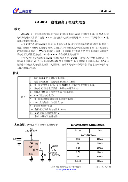
GC4054 线性锂离子电池充电器描述GC4054 是一款完整的单节锂离子电池采用恒定电流/恒定电压线性充电器。
其 S OT 封装与较少的外部元件数目使得 GC4054 成为便携式应用的理想选择。
GC4054 可以适合 USB 电源和适配器电源工作。
由于采用了内部 P MOSFET 架构,加上防倒充电路,所以不需要外部检测电阻器和 隔离二极管。
热反馈可对充电电流进行调节,以便在大功率操作或高环境温度条件下对 芯片温度加以限制。
充电电压固定于 4.2V ,而充电电流可通过一个电阻器进行外部设置 当充电电流在达到最终浮充电压之后降至设定值 1/10 时,GC4054 将自动终止充电循环。
当输入电压(交流适配器或 U SB 电源)被拿掉时,GC4054 自动进入一个低电流状态,将电池漏电流降至 2uA 以下。
也可将 G C4054 置于停机模式,以而将供电电流降至45uA 。
GC4054 的其他特点包括充电电流监控器、欠压闭锁、自动再充电和一个用于指 示充电结束和输入电压接入的状态引脚。
特点特点1:高达 800mA 的可编程充电电流;2:无需 MOSFET 、检测电阻器或隔离二极管;3:用于单节锂离子电池、采用 SOT23-5 封装的完整线性充电器; 4:恒定电流/恒定电压操作,并具有热调节功能; 5:直接从 USB 端口给单节锂离子电池充电;6:4.2V 预设充电电压;7:用于电池电量检测的充电电流监控器输出; 8:C/10 充电终止;自动再充电; 9:充电状态输出引脚10:待机模式下的供电电流为 45uA; 11:2.9V 涓流充电器件版本; 12:软启动限制了浪涌电流;典型应用:500mA 单节锂离子电池充电器 Rprog电阻和充电电流Ibat对应表RprogIbatI bat =1000/R prog 10K 100mA 5K 200mA 3.3K 300mA 2.5K 400mA 2K500mA 1.65K600mA引脚分布引脚功能绝对最大额定值输入电源电压4.5V~6V PROG -0.3V~VCC+0.3VBAT -0.3V~7V CHRG-0.3V~10VBAT 短路持续时间 连续 BAT 引脚电流 800mA PROG 引脚电流800uA 最大结温 145℃ 工作环境温度范围 -20℃~85℃ 贮存温度范围 -65℃~125℃引脚温度(焊接时间10s)260℃CHRG(引脚1)漏极开路充电状态输出。

应急灯8-Bit Flash单片机HT45FH4J2014-12-03版本: V1.00 日期: 2014-12-03Rev. 1.00 22014-12-03HT45FH4J应急灯8-Bit Flash 单片机目 录特性 (6)CPU 特性 (6)周边特性 (6)应急灯应用特性 (6)概述 (7)方框图 (7)引脚图 (8)引脚说明 (9)极限参数 (11)直流电气特性 (11)交流电气特性 (13)LVD & LVR 电气特性 (14)ADC 电气特性 (15)LDO 稳压器电气特性 (15)过电流保护电气特性 (16)上电复位特性 (16)系统结构 (17)时序和流水线结构 (17)程序计数器 (18)堆栈 (18)算术逻辑单元 – ALU (19)Flash 程序存储器 (19)结构 (19)特殊向量 (19)查表 (20)查表范例 (20)在线烧录 (21)片上调试 (22)数据存储器 (23)结构 (23)特殊功能寄存器 (25)间接寻址寄存器 – IAR0, IAR1 (25)间接寻址指针 – MP0, MP1 (25)存储区指针 – BP (26)累加器 – ACC (26)程序计数器低字节寄存器 – PCL (26)表格寄存器 – TBLP, TBHP, TBLH (26)状态寄存器 – STATUS (27)HT45FH4J应急灯8-Bit Flash 单片机Rev. 1.00 32014-12-03EEPROM 数据存储器 ..................................................................................................29EEPROM 数据存储器结构 .. (29)EEPROM 寄存器 (29)从 EEPROM 中读取数据 (31)写数据到 EEPROM (31)写保护 (31)EEPROM 中断 (31)编程注意事项 (32)振荡器 (33)振荡器概述 (33)系统时钟配置 (33)内部RC 振荡器 – HIRC (33)内部32kHz 振荡器 – LIRC .................................................................................................34工作模式和系统时钟 . (34)系统时钟 (34)系统工作模式 (35)控制寄存器 (36)工作模式切换 (37)待机电流的注意事项 (40)唤醒 (40)看门狗定时器 (41)看门狗定时器时钟源 (41)看门狗定时器控制寄存器 (41)看门狗定时器操作 (42)复位和初始化 (43)复位功能 (43)复位初始状态 (45)输入/输出端口 (49)上拉电阻 (49)PA 口唤醒 (50)输入/输出端口控制寄存器 (50)引脚共用功能 (51)引脚共用寄存器 (51)输入/输出引脚结构 (52)编程注意事项 (53)定时器模块 – TM (54)简介 (54)TM 操作 (54)TM 时钟源 (54)TM 中断 (54)TM 外部引脚 (55)TM 输入/输出引脚控制 (55)编程注意事项 (56)Rev. 1.00 42014-12-03HT45FH4J应急灯8-Bit Flash 单片机周期型TM – PTM (57)周期型 TM 操作 (57)周期型 TM 寄存器介绍 (57)周期型 TM 工作模式 (61)A/D 转换器.....................................................................................................................69A/D 简介 . (69)A/D 转换寄存器介绍 (69)A/D 转换器数据寄存器 – SADOL, SADOH (70)A/D 转换控制寄存器 – SADC0, SADC1 (70)A/D 操作 (72)A/D 输入引脚 (73)A/D 转换率及时序图 (73)A/D 转换步骤 (74)编程注意事项 (75)A/D 转换功能 (75)A/D 转换应用范例 (76)互补式 PWM 输出 (78)过电流保护 (80)过电流保护操作 (80)过流保护控制寄存器 (81)输入电压范围 (84)失调电压校准 (84)应急灯应用说明 (86)市电正常,进行充电 (86)市电正常,模拟电池升压供电照明 (86)蜂鸣器驱动方式 (86)LED 照明驱动方式 (86)高压MOS (87)控制寄存器 (89)中断 (91)中断寄存器 (91)中断操作 (96)外部中断 (97)OCP 中断 (97)多功能中断 (97)A/D 转换器中断 (97)时基中断 (98)EEPROM 中断 (99)LVD 中断 (99)TM 中断 (99)中断唤醒功能 .......................................................................................................................99编程注意事项 (100)HT45FH4J应急灯8-Bit Flash 单片机Rev. 1.00 52014-12-03低电压检测 – LVD (101)LVD 寄存器 ........................................................................................................................101LVD 操作 ............................................................................................................................102配置选择项 ..................................................................................................................102应用电路 . (103)应急灯应用电路(LED 功率低于0.6W ) .......................................................................103应急灯应用电路(LED 功率高于1W ) ..........................................................................104指令集 .. (105)简介 .....................................................................................................................................105指令周期 .............................................................................................................................105数据的传送 .........................................................................................................................105算术运算 .............................................................................................................................105逻辑和移位运算 .................................................................................................................105分支和控制转换 .................................................................................................................106位运算 .................................................................................................................................106查表运算 .............................................................................................................................106其它运算 .............................................................................................................................106指令集概要 (107)惯例 .....................................................................................................................................107指令定义 ......................................................................................................................110封装信息 . (122)16-pin NSOP (150mil) 外形尺寸 ........................................................................................12320-pin SSOP (150mil) 外形尺寸 . (124)Rev. 1.00 62014-12-03HT45FH4J应急灯8-Bit Flash 单片机特性CPU 特性●内建LDO ,高压输入高达12V ,输出5V 作为单片机工作电压●V DD =5V ,系统时钟为20MHz 时,指令周期为0.2μs●提供暂停和唤醒功能,以降低功耗●振荡器类型: ♦内部12/16/20MHz 高速RC – HIRC ♦内部低速32kHz RC – LIRC●多种工作模式:正常、低速、空闲和休眠●所有指令都可在1或2个指令周期内完成●查表指令●63条指令●4层堆栈●位操作指令周边特性●Fla s h 程序存储器:2K ×16●RAM 数据存储:128×8●EEPROM 存储器:64×8●看门狗定时器●12个双向I/O 口●2个引脚与外部中断口共用●多个定时器模块用于时间测量、捕捉输入、比较匹配输出、PWM 输出及单脉冲输出●2对带死区时间控制的互补PWM 输出●1个带中断的过电流保护功能●双时基功能用以产生固定的中断信号●6个外部通道的12-bit A/D 转换器●低电压复位功能●低电压检测功能●封装类型:16-pin NSOP ,20-pin SSOP应急灯应用特性●内建一个5V LDO 供应单片机、LED 指示灯以及其它电路●读取内建电阻分压可用于DC/DC 升压闭环控制●内建PMOS 元件以及驱动外接NMOS 用于DC/DC 升降压控制●内建0.6W LED 照明驱动电路●支持外接NMOS 驱动高功率LED●Buzzer 高压驱动输出●内建开关可完成产品电池及LED 照明自检要求HT45FH4J应急灯8-Bit Flash 单片机Rev. 1.00 72014-12-03概述HT45FH4J 是一款应急灯专用ASSP Fla s h 单片机。
PHOENIX ELITE PORTABLE SOLAR GENERATOREN01 USER GUIDE驭光者·火鸟ELITE太阳能手提式移动电源箱CN18PHOENIX ELITE PORTABLE SOLAR GENERATORUser GuideIMPORTANT SAFETY INSTRUCTIONS PACKAGE CONTENTS FEATURESRECHARGING PHOENIX ELITE LCD SCREENPRODUCT OVERVIEW SPECIFICATIONS TROUBLESHOOTINGFREQUENTLY ASKED QUESTIONS WARRANTYOPERATING PHOENIX ELITE MAINTENANCE 171613131108070604030302Please read the User Guide carefully before recharging or operating your PHOENIX Elite.IMPORTANT SYMBOLSIndicates potentially dangerous conditions that could result in personal injury Indicates conditions or practices that could result in damages to the unit or other equipmentIndicates procedures or functions that are important for proper and safe operation of the unit and/or other equipmentCAUTIONCAUTION CAUTION CAUTIONWARNINGWARNINGWARNINGWARNINGWARNINGWARNINGNOTEDO NOT submerge the unit in water or operate the unit in the rain. Doing so may cause short-circuits, electric shocks, and/or fire.DO NOT place the unit near fire and/or heat the unit. Doing so may cause irreversible damages to the unit and/or battery explosion.DO NOT overload the unit. Please check the specifications of output ports and devices before operation.Please turn off the output ports when no devices are connected to the unit to prevent electric shocks.DO NOT dismantle or modify the unit. Doing so may cause irreversible damages to the unit and void warranty.CAUTIONDO NOT place the unit in high-temperature situations. Doing so may cause unit malfunction or component degradation.CAUTIONDO NOT expose the unit to strong electrostatic fields, strong magnetic fields, and/or radiation.CAUTIONPlease check the unit before each use. Stop using the unit if you notice unusual smells, heating, distortion, or any other abnormalities.DO NOT drop or strike the unit. Doing so may cause circuit failures and cracks in the casing.Please dispose of the product according to the local recycling and environmental regulations.Keep the unit out of the reach of young children.PORTABLE DESIGNFeaturing a portable briefcase design with a sturdy carrying handle, the PHOENIX Elite is the top choice for a weekend trip or an emergency.RENEWABLE ENERGYDesigned for off-grid applications, the PHOENIX Elite combines two highly efficient 10W monocrystalline solar panels for effortless battery replenishment.DIVERSE RECHARGING OPTIONSEngineered with convenience and versatility in mind, the PHOENIX Elite supports recharging from car sockets, AC adapters, USB-C wall chargers, and external solar panels.RELIABLE POWER SOURCEEquipped with a 300Wh rechargeable lithium-ion battery pack and multiple output ports, the PHOENIX Elite is ready to provide long-lasting power for a wide range of mobile devices and small appliances.1 x Renogy PHOENIX Elite Portable Solar Generator1 x AC/DC Adapter1 x Cigarette Lighter Plug to 5.5mm DC Adapter Cable1 x Solar Panel Connectors to 5.5mm DC Adapter Cable1 x USB-C to USB-C Cable1 x User Guide76 12345891011121314CIG Port Output Side DoorDC Output Ports QC USB-A Port USB-A Ports Hinges Input Side Door 15DC Input Port 16USB-C PD Port 17LED Flashlight 18Carrying Handle1914131211109Flashlight On/Off Button Main Power ButtonAC Output Mode On/Off Button DC Output Mode On/Off Button LCD Screen Built-in Solar Panels Latches AC Outlet 876543211516171819InputBatteryGeneralLithium-ion 14.4V20800mAh / 299.5Wh Battery Type Battery Voltage Battery CapacityBuilt-in Solar Panel DC Input Port USB-C PD Port Total9.8V / 2.04A, 20W Max 9-16.8V, 55W Max 16.8-30V, 100W Max5V / 3A, 9V / 3A, 12V / 3A, 15V / 3A, 20V / 3A, 60W Max 180W Max 413 x 308 x 100 mm / 16.3 x 12.1 x 3.9 inch 5.3 kg / 11.7 lb.ABS + PC 3W LED0-45 ℃ / 32-113 ℉-10-60 ℃ / 14-140℉20-90%Dimension Weight Material FlashlightNormal Operating Temperature Storage Temperature Operating / Storage HumidityOutputUSB-A Port (2)QC USB-A Port USB-C PD Port CIG PortDC Output Port (2)AC OutletTotal5V / 2.4A Max5V / 3A, 9V / 2A, 12V / 1.5A, 18W Max5V / 3A, 9V / 3A, 12V / 3A, 15V / 3A, 20V / 3A, 60W Max 13.6V / 9A Max 13.6V / 4.5A Max 110V / 60Hz (US, JP, CA)220V / 50Hz (AU, EU, CN)200W Rated, 300W Surge Pure Sine Wave300W MaxThe LCD Screen will be lit when the PHOENIX Elite is being recharged or turned on to display the recharging and operating status of the PHOENIX Elite. Please refer to the following table to interpret the information displayed on the LCD Screen.The Battery Level is displayed as a ring composed of 10 segments with a percentage in the center. The ring and percentage appear when the PHOENIX Elite is being recharged or is turned on. When recharging the PHOENIX Elite, a lightning bolt will appear above the percentage. The ring will be lit segment by segment with the increasing percentage until the PHOENIX Elite has been fully recharged. As the PHOENIX Elite is used to power other devices, the ring segments will go out one by one with the decreasing percentage. When the battery level is lower than 10%, the last ring segment and the percentage will flash.IconNameDescriptionBattery LevelThe AC Output Mode is displayed as a rectangle with the words ‘AC Output’ inside. The rectangle appears when the AC output mode is activated with the AC Outlet turned on. The rectangle disappears when the AC output mode is deactivated with the AC Outlet turned off.AC Output ModeAC Output The DC Output Mode is displayed as a rectangle with the words ‘DC Output’ inside. The rectangle appears when the DC output mode is activated with the USB-A Ports, QC USB-A Port, USB-C PD Port, CIG Port, and DC Output Ports turned on. The rectangle disappears when the DC output mode is deactivated with the USB-A Ports, QC USB-A Port, USB-C PD Port, CIG Port, and DC Output Ports turned off.DC Output ModeThe Built-in Solar Panel Input is displayed as a sun with 5 bars below it. The sun and bars appear when the PHOENIX Elite detects input power from the Built-in Solar Panel. The number of bars demonstrates the strength of solar irradiance.Built-in Solar Panel InputThe Input Power is displayed as a wattage with the word ‘Input’ above it. The wattage appears when the PHOENIX Elite is being recharged.Input PowerThe Output Power is displayed as a wattage with the word ‘Output’ above it. The wattage appears when the AC output mode or the DC output mode is activated.Output PowerThe Error Code is displayed as a 3-digit code starting with the letter ‘E’. The code appears when the PHOENIX Elite encounters abnormal conditions.Error CodeDC OutputIf the [Error Code] icon appears, the PHOENIX Elite may need special attention. Please refer to the TROUBLESHOOTING section for help.CAUTIONTo maximize the battery life, please ensure that the PHOENIX Elite is fully recharged before operating or storing.To shorten the recharge time, it is highly recommended to disconnect all loads while recharging the PHOENIX Elite.CAUTIONNOTEThe above recharge times are based on conditions when the PHOENIX Elite is recharged at full speed with no loads connected to it.NOTEThe LCD Screen will go out if the input power of the Built-in Solar Panels is lower than 5W and no operations are made within 60 seconds. Press the AC Output Mode On/Off Button or DC Output Mode On/Off Button to relight the LCD Screen.NOTEThe recharge time via the Built-in Solar Panels is highly dependent on solar irradiance and ambient temperature.NOTERecharge TimeRecharge via Built-in Solar Panel: 20 Hours Recharging via Built-in Solar PanelFor optimal recharging performance, it is highly recommended to recharge the PHOENIX Elite using the Built-in Solar Panels on bright sunny days free of scattered clouds.Recharging via External Solar PanelFor optimal recharging performance, it is highly recommended to recharge the PHOENIX Elite using an external solar panel (not included) on bright sunny days free of scattered clouds.Place the external solar panel under direct sunlight. Steer clear of trees or branches that can shade the external solar panel and slow down the recharging process.Place the PHOENIX Elite in an open area. Open the Latches and adjust the angle of the Hinges to expose the Built-in Solar Panels to direct sunlight. Steer clear of trees or branches that can shade the Built-in Solar Panel and slow down the recharging process.The PHOENIX Elite will begin to recharge automatically. The LCD Screen will be lit with the [Battery Level] icon, [Built-in Solar Panel Input] icon, and [Input Power] icon appearing.Recharge via External Solar Panel: 4 HoursRecharge via both Built-in Solar Panel and External Solar Panel: 3.5 Hours Recharge via AC/DC Adapter: 6 Hours Recharge via Car Socket: 6 HoursRecharge via USB-C PD Wall Charger: 6 HoursRecharge via both AC/DC Adapter and USB-C PD Wall Charger: 3 HoursUse the included Solar Panel Connectors to 5.5mm DC Adapter cable to connect the external solar panel to the DC Input Port of the PHOENIX Elite. Place the PHOENIX Elite in the shade to prevent it from overheating.The PHOENIX Elite will begin to recharge automatically. The LCD Screen will be lit with the [Battery Level]icon and [Input Power] icon appearing.Compatible External Solar Panels:Renogy Monocrystalline Solar Panel: 50W, 80W, 100W, 160WRecharging via AC/DC Adapter Plug the PHOENIX Elite into a wall outlet through the DC Input Port using the included AC/DC Adapter.Renogy Polycrystalline Solar Panel: 50W, 100WRenogy ECLIPSE Series Solar Panel: 100WRenogy Monocrystalline Foldable Solar Suitcase w/o Controller: 100WRenogy ECLIPSE Series Foldable Solar Panel w/o Controller: 100W, 200WRenogy Flexible Solar Panel: 50W, 100W, 160W, 175WRenogy E.FLEX Series Portable Solar Panel: 50W, 100W, 120W CAUTION WARNING NOTEElectrical shock can occur if the Solar Panel Connectors to 5.5mm DC Adapter Cable isdamaged or frayed. DO NOT use a damaged or frayed cable to recharge the PHOENIX Elite.Please ensure that the open circuit voltage of the external solar panel does not exceed 30V orfall short of 9V.The recharge time via the external solar panel is highly dependent on solar irradiance andambient temperature.The PHOENIX Elite will begin to recharge automatically. The LCD Screen will be lit with the [Battery Level] icon and [Input Power] icon appearing.Recharging via Car SocketPlug the PHOENIX Elite into a car socket through the DC Input Port using the included Cigarette Lighter Plug to 5.5mm DC Adapter Cable.The PHOENIX Elite will begin to recharge automatically. The LCD Screen will be lit with the [Battery Level] icon and [Input Power] icon appearing.WARNINGElectrical shock can occur if the AC/DC Adapter is damaged. DO NOT use a damaged AC/DC Adapter to recharge the PHOENIX Elite.WARNING DO NOT use a third-party AC/DC adapter to charge the PHOENIX Elite. Doing so may cause the AC/DC adapter to overheat and/or fire.WARNING Electrical shock can occur if the Cigarette Lighter Plug to 5.5mm DC Adapter Cable is damaged or frayed. DO NOT use a damaged or frayed cable to recharge the PHOENIX Elite.CAUTIONPlease disconnect the PHOENIX Elite from the car socket when starting the engine. Electricalsurges from the alternator when starting may damage the PHOENIX EliteRecharging via USB-C PD Wall ChargerFor optimal recharging performance, it is highly recommended to recharge the PHOENIX Elite using a USB-C PD wall charger (not included) with a high power rating.Plug the PHOENIX Elite into a wall outlet through the USB-C PD Port using the USB-C PD wall charger and the included USB-C to USB-C Cable.The PHOENIX Elite will begin to recharge automatically. The LCD Screen will be lit with the [Battery Level] icon and [Input Power] icon appearing.WARNINGElectrical shock can occur if the USB-C PD wall charger is damaged. DO NOT use a damagedUSB-C PD wall charger to recharge the PHOENIX Elite.Recommended USB-C PD Wall Chargers:Apple USB-C Power Adapter: 30W, 61W, 87W, 96WOperation Time Battery Powered Devices:Google USB-C Power Adapter: 45WOperating the PHOENIX Elite at high temperature above 113℉ (45℃) or at low temperatures below 32℉ (0℃) can result in battery performance degradation and service life shortening. Foroptimal battery performance and maximum battery life, it is highly recommended to operate the PHOENIX Elite at room temperatures. CAUTION OPERATING PHOENIX ELITENumber of Full Charges =Device Battery Capacity (Wh)299.5Wh x 70%Powering DevicesPress the Main Power Button to turn on the PHOENIX Elite. The LCD Screen will be lit with the [Battery Level] icon appearing.Compatible DevicesUSB-A Ports / QC USB-A Ports: Smart Watch, Electronic Book, Smart Phone, Tablet, Action Camera, Digital Camera, Bluetooth Speaker, Wireless Headphone, Drone, and other USB-A enabled devicesUSB-C PD Ports: Smart Phone, Tablet, Laptop, Handheld Game Console, DSLR Camera, and other USB-C enabled devicesCIG Port: Portable Refrigerator, Car Vacuum, Car Air Fan, CPAP Machine, and other car powered devices DC Output Ports: LED Strip Light, Modem, Router, Motor, and other DC powered devicesAC Outlet: Laptop, Monitor, TV, Game Console, Inkjet Printer, Portable Projector, Light Bulb, and other AC Powered DevicesTo use the USB-A Ports, QC USB-A Port, USB-C PD Port, CIG Port, or DC Output Ports, first press the DC Output Mode On/Off Button to activate the DC output mode. The [DC Output Mode] icon and [Output Power] icon will appear. Then, connect the device(s) to the port(s) for power. The [Output Power] icon will show the real-time output power. When not using the port(s), long press the DC Output Mode On/Off Button to deactivate the DC output mode. The [DC Output Mode] icon and [Output Power] icon will disappear.To use the AC Outlet, first press the AC Output Mode On/Off Button to activate the AC output mode. The [AC Output Mode] icon and [Output Power] icon will appear. Then, connect the device to the outlet for power. The[Output Power] icon will show the real-time output power. When not using the outlet, long press the AC Output Mode On/Off Button to deactivate the AC output mode. The [AC Output Mode] icon and [Output Power] icon will disappear.When no device is connected to the PHOENIX Elite, press the Main Power Button again to turn it off.DC Powered Devices:Working Hours =Device Power Rating (W )299.5Wh x 95%AC Powered Devices:Working Hours =Device Power Rating (W )299.5Wh x 85%NOTE The above estimation formulas only apply when the PHOENIX Elite has been fully recharged and the device does not draw too much power.NOTEActual number of full charges and working hours may vary due to different powering methods and device operation status.WARNINGThe PHOENIX Elite can provide up to 300W total output power. Allocate the total output powerrationally and follow the specifications of each output port. DO NOT overload the PHOENIXElite. If the total output power should exceed 300W, the AC Outlet will be shut off.Using LED FlashlightPress the Main Power Button to turn on the PHOENIX Elite. The LCD Screen will be lit with the [Battery Level] icon appearing.When not using the LED Flashlight, press the Main Power Button to turn off the PHOENIX Elite.The LED Flashlight has three lighting modes: bright (100% brightness), dim (50% brightness), and SOS. Press the Flashlight On/Off Button to turn on the LED Flashlight, switch lighting modes, and turn off the LED Flashlight. Long press the Flashlight On/Off Button to turn off the LED Flashlight no matter what lighting mode it is on.To prolong the service life of the PHOENIX Elite, keep it away from water, dust, and dirt. DO NOT leave the PHOENIX Elite in harsh environments.Keep the PHOENIX Elite away from corrosives, fire, and heat sources.Keep the PHOENIX Elite recharged when not in use and avoid connecting devices with high power ratings when the battery level is low.If the PHOENIX Elite does not operate normally, please refer to the following table for possible causes and corrective steps.If the following corrective steps do not work, please contact the Renogy technical support team for help. Refer to the last page of the User Guide for contact information.If the PHOENIX Elite is not used frequently, keep its battery level at around 50%. Store the PHOENIX Elite in a clean, dry, and well-ventilated environment with a temperature around 77℉ (25℃) and a humidity no higher than 75%. Recharge the PHOENIX Elite at least once every two months.NOTE The PHOENIX Elite may not be compatible with the devices that require high current impulses despite their conformity with the output ports specifications.NOTEThe PHOENIX Elite may not be able to deliver exactly 299.5Wh of energy when poweringdevices with high power ratings. Battery high temperature protection may be triggered when the PHOENIX Elite is operating at full load. Cool down the PHOENIX Elite before resuming operation. CAUTIONWhen using the AC Outlet, keep 4 inches of space on either side of the PHOENIX Elite to guarantee efficient heat dissipation.CAUTION When the battery level drops to 0%, the PHOENIX Elite will turn off automatically. Please recharge the PHOENIX Elite as soon as possible to avoid permanent damage to the battery.CAUTION When the battery level drops below 10%, use of the AC Outlet will be disabled. If the total outputpower still exceeds 200W, use of the CIG Port and DC Output Ports will be subsequentlydisabled. DO NOT connect devices with high power ratings to the PHOENIX Elite when the battery level is low. CAUTIONDisconnect all the power source(s). Discharge the unit untilthe [Error Code] icon disappears.Error CodePossible Causes Corrective Steps E01Battery Over-voltage Disconnect all the electrical load(s). Recharge the unit untilthe [Error Code] icon disappears.E02Battery Under-voltage Stop using the unit. Contact the Renogy technical supportteam for help.E03Battery Cell Imbalance Stop using the unit. Contact the Renogy technical supportteam for help.E04BMS Communication Failure Disconnect all the power source(s) and electrical load(s).Cool down the unit until the [Error Code] icon disappears.E05Battery High Temperature (Charge)Disconnect all the power source(s) and electrical load(s).Warm up the unit until the [Error Code] icon disappears.E06Battery Low Temperature (Charge)Disconnect the power source. Check the voltage rating ofthe power source. Connect only the power source withcompliant voltage rating to the unit.E07DC Input Port Over-voltage Disconnect the power source. Check the voltage rating ofthe power source. Connect only the power source withcompliant voltage rating to the unit.E08DC Input Port Under-voltage Disconnect the power source. Check the voltage rating ofthe power source. Connect only the power source withcompliant voltage rating to the unit.E09USB-C PD Port Input Over-voltage Disconnect the power source. Check the voltage rating ofthe power source. Connect only the power source withcompliant voltage rating to the unit.E10USB-C PD Port Input Under-voltage Reconnect all the power source(s). If the [Error Code] iconpersists, stop using the unit. Contact the Renogy technicalsupport team for help.E11Charge Over-current Disconnect all power source(s) and electrical load(s). Cooldown the unit until the [Error Code] icon disappears.E12Battery High Temperature (Discharge)Disconnect all power source(s) and electrical load(s). Warmup the unit until the [Error Code] icon disappears.E13Battery Low Temperature (Discharge)Disconnect the electrical load(s). Reactivate the DC outputmode. If the [Error Code] icon persists, stop using the unit.Contact the Renogy technical support team for help.E14USB-A Ports Output Over-voltageContact the Renogy technical support team for help.Under-voltage Disconnect the electrical load(s). Remove the shortcircuit(s). Press the DC Output Mode On/Off Button to clearthe [Error Code] icon. Connect only the electrical load(s)with compliant current ratings to the unit.E16USB-A Ports Output Over-current/Short-circuit Disconnect the electrical load(s). Reactivate the DC outputmode. If the [Error Code] icon persists, stop using the unit.Contact the Renogy technical support team for help.E17DC Output Ports/CIG Port Output Over-voltage Disconnect the electrical load(s). Reactivate the DC outputmode. If the [Error Code] icon persists, stop using the unit.Contact the Renogy technical support team for help.E18DC Output Ports/CIG Port Output Under-voltage Disconnect the electrical load(s). Remove the shortcircuit(s). Press the DC Output Mode On/Off Button to clearthe [Error Code] icon. Connect only the electrical load(s)with compliant current ratings to the unit.E19DC Output Ports/CIG Port Output Over-cur-rent/Short-circuit Disconnect the electrical load. Reactivate the DC outputmode. If the [Error Code] icon persists, stop using the unit.Contact the Renogy technical support team for help.E20QC USB-A Port Output Over-voltage Disconnect the electrical load. Reactivate the DC outputmode. If the [Error Code] icon persists, stop using the unit.Contact the Renogy technical support team for help.E21QC USB-A Port Output Under-voltage Disconnect the electrical load. Remove the short circuit.Press the DC Output Mode On/Off Button to clear the [ErrorCode] icon. Connect only the electrical load with compliantcurrent ratings to the unit.E22QC USB-A Port Output Over-current/Short-circuit Disconnect the electrical load. Reactivate the DC outputmode. If the [Error Code] icon persists, stop using the unit.Contact the Renogy technical support team for help.E23USB-C PD Port Output Over-voltage Disconnect the electrical load. Reactivate the DC outputmode. If the [Error Code] icon persists, stop using the unit.Contact the Renogy technical support team for help.E24USB-C PD Port Output Under-voltage Disconnect the electrical load. Remove the short circuit.Press the DC Output Mode On/Off Button to clear the [ErrorCode] icon. Connect only the electrical load with compliantcurrent ratings to the unit.E25USB-C PD Port Output Over-current/Short-circuit Disconnect the electrical load. Remove the short circuit. Letthe unit stand for 10 seconds. Press the AC Output ModeOn/Off Button to clear the [Error Code] icon. Connect onlythe electrical load with compliant power ratings to the unit.E26AC Outlet Output Overload/Short-circuitFirst, make sure that the unit has been turned on by pressing the Main Power Button. If the LCD Screen does not light up after pressing the Main Power Button, please recharge the unit as soon as possible. Then, make sure that the output ports have been turned on by pressing the AC Output Mode On/Off Button and/or DC Output Mode On/Off Button. Finally, make sure that the connected devices conform to the specifications of the output ports. If the [Error Code] icon appears, please see the TROUBLESHOOTING section or contact the Renogy technical support team for help. Refer to the last page of the User Guide for contact information.Contact the Renogy technical support team for help.Over-voltageDisconnect the electrical load. Reactivate the AC output mode. If the [Error Code] icon persists, stop using the unit.Contact the Renogy technical support team for help.E28AC Outlet OutputUnder-voltage Disconnect all the power source(s) and electrical load(s).Cool down the unit to the room temperature. Press the ACOutput Mode On/Off Button to clear the [Error Code] icon.E29Inverter High Temperature Disconnect all the electrical load(s). Press the AC OutputMode On/Off Button to clear the [Error Code] icon.Reallocate the total output power. E30Total Output Overload1. Why doesn't the PHOENIX Elite power external devices?No, the battery in PHOENIX Elite is not replaceable. Do not try to dismantle the PHOENIX Elite and replace the battery by yourself. Doing so may cause irreversible damages to the unit and/or battery explosion.2. Can I replace the battery in the PHOENIX Elite?No, the PHOENIX Elite cannot be chained together or with other rechargeable AC power supplies. If you are looking for a rechargeable AC power supply with a large capacity,, please visit our website or contact us for more options. Refer to the last page of the User Guide for contact information.3. Is the PHOENIX Elite chainable?No, the PHOENIX Elite is not waterproof. Please keep the unit away from moisture. Do not submerge the unit into water or operate the unit in the rain. Doing so may cause short-circuit, electric shocks, and fire.4. Is the PHOENIX Elite waterproof?The battery capacity of the PHOENIX Elite is rated at 0.2C. When the PHOENIX Elite is powering devices with high power ratings, the internal resistance of the battery will turn more energy into heat and lower the energy conversion efficiency. As a result, you may not get exactly 299.5Wh of energy.5. Why doesn't the PHOENIX Elite last as long as I expect?RENOGY products are covered by a 12-month limited warranty from the original purchase date. If any problems occur, please contact us for assistance. Refer to the last page of the User Guide for contact informa-tion.We only provide after-sales services for products that are sold by RENOGY or retailers and distributors authorized by RENOGY. If you have purchased your unit from other channels, please contact your seller for more information about return and warranty.Please register your purchase(s) directly at /support/tickets/new or your region’s corresponding website so that we can stay in touch and contact you in the unlikely event that a safety recall is required.驭光者·火鸟ELITE太阳能手提式移动电源箱用户指南安全操作准则产品配件产品特性为火鸟Elite充电LCD 屏幕产品概况产品参数故障排除常见问题售后质保使用火鸟Elite 维护343331312926252422212120请在为本机充电或使用本机前仔细阅读用户指南。
FLUKE 45 用户手册1.1一般性技术指标1.1.1检定周期为一年;1.1.2工作环境温度为18℃-28℃;1.1.3工作环境相对湿度不超过90%(非结露),电阻档1000kΩ以上量程相对湿度不超过70%。
精度表达形式为:±(读数%+字)2.1直流电压:2.2真有效值交流电压:2.3直流电流:2.4交流电流:2.5电阻:2.6频率:3 FLUKE-45 数字式多用表操作规范3.1使用多用表前的准备:3.1.1连接电源线,并按下电源开关,此时数表开机自检,前面板的显示器点亮,开机后,多用表将自动处于直流电压测试功能状态,自动量程有效。
3.1.2多用表使用前应预热,从开机到测试至少预热30分钟,以使内部各零件处于稳定状态,关机后重新开机需再预热,时间应大于两倍关机时间(最多30分钟)。
3.2用多用表进行测量:FLUKE-45数字式多用表进行电压、电流、电阻、频率等参数测量的步骤、方法及操作参见《FLUKE-45使用说明》。
测量中一般选用数表的自动量程转换功能,以免应误操作而损坏设备。
3.3使用后的注意事项:3.3.1测量结束应拔下测试线(表笔)妥善放置,以免下次测量时,因测量功能与输入插孔不对应而烧毁仪表。
3.3.2测量结束后关闭电源开关并拔去电源线,以防意外造成损坏。
4功能操作详解5使用比较功能比较功能(COMP)提供了一条简而易行的方法判别测量值是否超出了确定范围。
在比较模式下,仪器在主显示显示测量值,而在第二显示指示该值是高(HI),低(LO),抑或正好(PASS)落在确定范围内。
比较功能可用在很多测量功能中,例如:REL、MN MX、HOLD、和dB。
在使用该功能前,先要设定好用于比较的允许范围的最高和最低点数值,方法有三:* 可通过按下"2ND"键后,按"/\" (HI)或"\/" (LO)键来确定比较范围,此时显示的值将成为高(低)点界限值。
HOT充电器使用说明HOT充电器使用说明5iMX.c一,充电器参数:-电压值:DC11.0-18.0V AC100-240, -50/60HZ-最大充电功率50W4h5S!g8K#l9U.Y*U-最大放电功率5W-充电电流值:0.1-5.0A-放电电流值:0.1-1.0A%z7/~*o&C5}.c2G-单个电池的电流:300mah/cell /doc/286193461.html,,A8y,N'N:g'` J"d4Z -镍氢/镍镉电池个数:1-15cell-锂离子/聚合物级数:1-6节(注:支持Li-Fe电池,即A123)2}(d6i4d4o9f-PB电池电压:2-20V-重量:580g-尺寸:133*87*33mm二,如何外接电源?将跟充电器的的夹子夹到大功率的稳压电源或者开关电源上面,红色为正极,黑色为负极,电压允许范围:11~18v,电流要求5A以上,官方要求最低12v5a不要问12v10a会不会烧坏充电器,答案是肯定不会的,就像你200W的主机用500W的电源不会因为电源功率大而烧掉一样道理:?1E/n/\:L&B-B/X原配一堆充电线材,充电前,先将长的那根蕉插(公)以及T插(公)线接到充电器右侧的母蕉插里面(红正黑负),然后根据自己要冲的电池类型选择合适的适配线,再将适配线的T插(母)插到刚才那根长线的T插(母)上,最好接上要充的电池上面就可以了。
'R2O2S"b%三,使用方法简易说明(只讲解充镍氢以及锂电的流程):1;按键功能+z9~$@'c T9g5G+yBatt. Type%K)y8O5r:@;T)@Stop按钮:电池种类以及停止按钮,接电后即可使用该按钮在主菜单中进行切换,充电时可随时按此键停止;5e+A-h$L/m*Q0p Dec. / Inc.!{*Z'b&T,V+a< Status >按钮:减小以及增加按钮,设置各种数值时Dec.是减小,Inc.是增加,充电时按这两个按钮以浏览电池不同信息;!Q'C+v7J/@(I/doc/286193461.html,我爱模Enter按钮:开始以及确定按钮。
HT45FH4M 雙節移動電源解決方案
主要特徵
1. 電氣電氣規格規格
鋰電池容量為7.4V/3000mAh
輸入5.0V / USB Mini-B 輸出5.1V / 2.1A(Max) / USB A 靜態電流12 uA
放電效率最高92.31% (5V/900mA) 輸出ripple:100 mV
2. 充電特性
PWM 頻率為300kHz,Duty 為100階 充電效率約85% 自動偵測充電器接上
自動偵測充電器最大供電流能力 三階段充電特性
◆
涓電流充電(電池電壓<6V / 定電流100mA)
◆
定電流充電(6V<電池電壓<8.4V / 最大定電流1500mA) ◆
定電壓充電(電池電壓8.4V / 充電電流<50mA 停止充電)
3. 放電特性
PWM 頻率為300kHz, Duty 為100階 放電效率最高92.31% (5V/900mA) 自動偵測負載接上 定電壓輸出(5.1V) 最大輸出電流2.1A 電池電壓低於6V 停止輸出
4. 安全機制
充電時輸入端過電壓保護 充電時電池溫度保護0~ +40°C 放電時輸出端過電壓保護 放電時輸出端短路保護 放電時電池端過電流保護 放電時電池溫度保護-20~ +60°C
操作說明
1. 按鍵
按鍵按下:電量顯示2 sec
按鍵按下>3 sec: 打開手電筒照明功能開啟與關閉
2. LED顯示
藍LED: 電量顯示
黃LED: 使用中指示
紅LED: 充電中指示
LED顯示對應功能
黃色Led: 亮, 紅色LED: 不亮
電池電量低於25%
藍色: Led 1 亮, Led 2 & Led 3 & Led 4不亮
黃色Led: 亮, 紅色LED: 不亮
電池電量25%~50%
藍色: Led 1 & Led 2 亮, Led 3 & Led 4不亮
黃色Led: 亮, 紅色LED: 不亮
電池電量50%~75%
藍色: Led 1 & Led 2 & Led 3亮, Led 4不亮
黃色Led: 亮, 紅色LED: 不亮
電池電量75%~100%
藍色: Led 1 & Led 2 & Led 3 & Led 4亮
黃色Led: 3Hz閃爍, 紅色LED: 3Hz閃爍
過電壓/過電流/溫度保護中藍色: Led 1 & Led 2 & Led 3 & Led 4: 3Hz閃爍
黃色Led: 亮, 紅色LED: 不亮
正在對內部電池充電, 電池電量低於25% 藍色: Led 1 以1Hz閃爍, Led 2 & Led 3 & Led 4不亮
黃色Led: 亮, 紅色LED: 不亮
正在對內部電池充電, 電池電量25%~50% 藍色: Led 1亮, Led 2 以1Hz閃爍, Led 3 & Led 4不亮
黃色Led: 亮, 紅色LED: 不亮
正在對內部電池充電, 電池電量50%~75% 藍色: Led 1 & Led 2 亮, Led 3以1Hz閃爍, Led 4不亮
黃色Led: 亮, 紅色LED: 不亮
對內部電池充電, 電池電量75%~100% 藍色: Led 1 & Led 2 & Led 3亮,Led4以1Hz閃爍
黃色Led: 亮, 紅色LED: 亮
已充飽電, 電池電量100% 藍色: Led 1 & Led 2 & Led 3 & Led 4亮
黃色Led: 亮, 紅色LED: 不亮
內部電池電壓小於截止電壓, 停止放電藍色: Led 1 以3Hz閃爍, Led 2 & Led 3 & Led 4不亮
黃色Led: 亮, 紅色LED: 不亮
USB_OUT正在輸出5V
藍色: Led 4 & Led 3 & Led 2 & Led 1依序跑馬燈
硬體電路架構
Discharge: Bulk
Charge: Boost
Battery Voltage
detect Input / Output
Voltage detect
Battery current
detect
Precision Voltage Temp.
sensor
放電轉換效率曲線圖
註:輸出電流0.1A與0.2A時由於MCU與LED耗電導致轉換功率降低
轉換效率公式: 轉換效率= (Vout * Iout / V_battery * I_battery) * 100%
HT45FH4M 競爭優勢
Flash MCU, 提供在線仿真, 加快開發流程
內建5V LDO與2組Level shift
PWM frequency 線性調整, PWM frequency達300 kHz (Duty為100階), 互補式輸出with dead time
抗干擾能力佳
可實現同步整流(效率高, 92.31% @ 輸出5V / 900mA )
待機電流低, Demo board 實測為12uA (一般傳統方案只做到100uA 以下)
外部零件少
提供有競爭力價格及BOM cost 較好
使用HT45FH4M開發的移動電源可依照軟體修改各項充放電參數, 不僅成本較低, 針對不同需求的產品支援度也遠高於傳統方案。