移动电源说明书翻译
- 格式:doc
- 大小:2.68 MB
- 文档页数:12
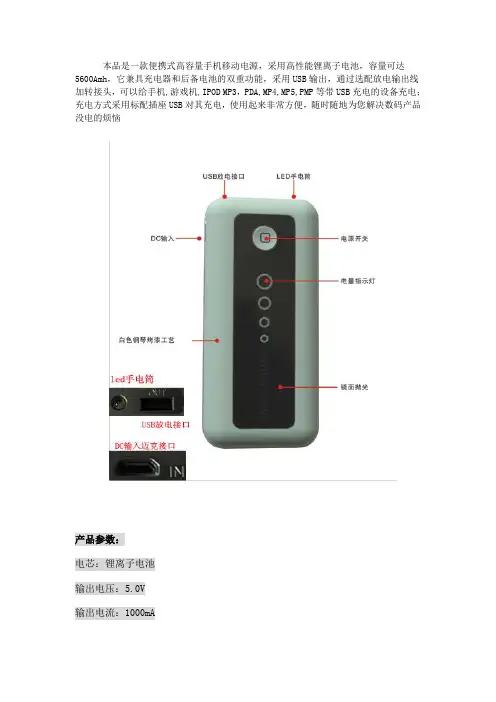
本品是一款便携式高容量手机移动电源,采用高性能锂离子电池,容量可达5600Amh,它兼具充电器和后备电池的双重功能,采用USB输出,通过选配放电输出线加转接头,可以给手机,游戏机,IPOD MP3,PDA,MP4,MP5,PMP等带USB充电的设备充电;充电方式采用标配插座USB对其充电,使用起来非常方便,随时随地为您解决数码产品没电的烦恼产品参数:电芯:锂离子电池输出电压:5.0V输出电流:1000mA输入电压:5.0V输入电流:1000mA容量:5600mAh充电时间:5-6.5小时(根据电池所“盛”电量)运行时间:5小时左右(依据市场上不同品牌,型号和操作模式而定)循环寿命:>400次工作温度:-10℃-40℃储存,运输温度:-20℃-50℃体积:90*57*20mm重量:120克携带方式:放在口袋,旅行背包,电脑包里或放在车里等电量显示:四灯指示,按下电源健,指示灯根据电量显示,第一(最大)指示灯表示剩余电量约为100%--75%,第二指示灯75%--50%,第三指示灯50%--25--%,第四指示灯25%--0。
给本移动电源充电显示:充电时从第四灯到第一灯按顺序亮,四灯都亮表示充电到100%充电方法:使用原装的电源适配器加上标配的充电转接头对本产品直接充电适用设备:适用于所有带USB充电的设备使用,如手机,PSP,IPOD,MP3,MP4,PMP,GPS,蓝牙,数码相机等。
思展宏都可以兼容3个数码充电接口一般都是常用型接口迈克接口迷你接口和iphone,ipad专用接口注意事项1.首先请检查被充电设备是否和该产品电压相兼容2.首次使用请确保产品充电时间为8小时以上3.请勿将输出电压调整到高于设备电压,否则有可能引起设备损坏,请在使用前一定确认清楚4.请使用指定充电器5.禁止短路,分解和抛入火中6.不得擅自拆卸充电器和电池对其进行改造7.注意防潮防水声明:擅自拆开产品,人为损坏,和超过保修期的产品,不在免费保修范围内。
规格说明1.容量:5200mAh2.输出电压:DC 5V3.输出电流:1000mA4.输入电压:DC 5.3V5.输入电流:1000mA操作1.按开关一下F 显示电量2.按开关两下F LED灯开3.按开关两下F LED等关4.插上USB按一下F电压输出5.充电指示当电量充满一格长亮二格灯闪当电量充满二格长亮三格灯闪当电量充满三格长亮四格灯闪当电量充满四格长亮充电结束6.放电指示当轻按开关电量显示四格当电量小于一格时再放电电量灯闪代表电量不足Specification1. capacity:5200mAh2. output voltage:DC 5V3. output current:1000mA4. input voltage:DC5.3V5. input current:1000mA1. Press the power switch F to indicate the battery level.2. Press the power switch F two times, the LED light on.3. Press the power switch F two times again, the LED light off.4. This Case can be charged by connected with the iPhone USB port. 5.Indication of chargingPress Switch F, one indicator light indicates 25% of the battery level;two indicator lights indicates 50%;three lights indicates 75%,and four lights indicates the case has been full charged.7.Indication of dischargingWhen the indicator light less than one the battery case is not enough power to use, you should charge it.。
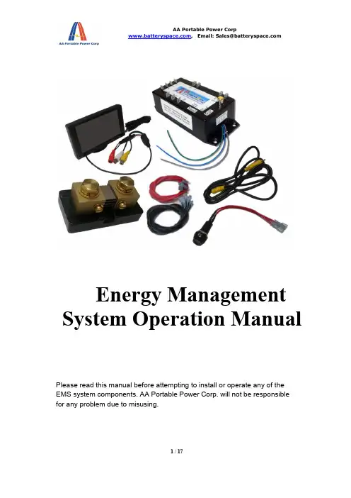
Energy Management System Operation ManualPlease read this manual before attempting to install or operate any of theEMS system components. AA Portable Power Corp. will not be responsiblefor any problem due to misusing.Catalogue1Introduction: (3)2Specification (3)3Typical diagram: (4)4Heart Beat LED (5)5Isolate Battery & Shunt connection: (6)612V Power: (6)7Monitor Page select switch: (7)8Sense Board Wiring: (7)9Battery balancing (9)10Video Output (10)11Can Bus Output (Optional) (10)12Main Screen: (11)13Individual Cell Page (12)14Alarms: (13)15Controlling Devices with Alarm Outputs (14)16Capacity Algorithm (14)17Ground Fault Detection (15)18Trouble Shooting (16)1Introduction:Thank you for purchasing Energy Management System (EMS). This manual covers the operating and installation information for this systemThe EMS system has everything needed to display the condition and maintain the health of lithium ion batteries and is specifically designed to work with GBS Lithium Ion batteries.The system consists of two major components, the computer Master (MASTER) and the cell sense boards. The MASTER shows details about the condition of the battery pack, such as current, voltage, state of charge and individual cell details, via its video output display. The sense boards form a simple daisy chain by mounting on each cell to read voltage and temperature; they also perform battery balancing during recharging to equalize the charge within the battery pack. Two alarm outputs, one for over voltage and one for under voltage, provide automatic shut off signals to prevent overcharging or over discharging of the battery pack. A unique feature of the EMS system is ground fault detection. High voltage systems should be floating relative to the chassis for safety. If an inadvertent path to the chassis ground is made the system will detect it and display a warning for this unsafe condition. The EMS outputs composite video to display battery pack information. A CAN (controller area network) interface option is available to output the information from the EMS to other systems.2Specificationoutputs3Typical diagram:The EMS is designed to make installation as easy as possible. All of the connections to it are made with convenient pluggable ¼” quick disconnect terminals. The EMS Master should be installed as close to the shunt as possible. The shunt sense wires should be less than 1’ long. A mounting template for the computer is shown in Appendix A. After the installation is complete, the battery pack must be completely charged before the capacity will read correctly (see Section 7.Capacity Algorithm for more details).Note: The EMS system components utilize either a conformal coating or rubberized coating on all components to allow them to perform in high humidity environments. They are not however water proof. All components must be installed inside water resistant containers.4Heart Beat LEDWhen the EMS is correctly connected to 12V, the heartbeat indicator will blink once per second5Isolate Battery & Shunt connection:The Terminals on the left side of the Master are used for making the High-Voltage and shunt connections. Refer to the figure below for these connections. The connections between the battery pack, shunt and high voltage loads are usually large wire (e.g. 2/0 depending on the max current of the system).The connections to the EMS from the battery and the shunt can be smaller gauge (e.g. 18 or 20 Awg).Note: Please use extreme caution when making these connections as the full battery pack potential will be present between the shunt and battery pack positive pins. Connecting these wires incorrectly can cause damage to the EMS MASTER which will not be covered under warranty.The wires connecting to the shunt should be a twisted pair or wires with as short of a distance from the MASTER as possible to achieve accurate measurements.612V Power:The MASTER is powered by 12 volt s, which is connected to the terminals marked “12V”and “GND”. This should be connected to a power source through a 5A fuse. The power can either be always on, or can be switched off to conserve power. 12 volt power must besupplied at any time when the battery pack is being charged or discharged. When 12 volt power is applied the red heartbeat LED will blink.If the battery pack is more than a 12 volt battery, and the MASTER is to be powered off of it,a DC/DC converter must be used so that the battery pack is discharged equally. Under nocircumstances can four cells within the battery pack be tapped for 12 volt power for the MASTER as this will cause an imbalance within the battery pack.Note: T here are three pins marked “GND” for ground on the MASTER. These three pins are common together. Only one of these pins needs to be connected, the other two are located for convenient connection options. It is not chassis.7Monitor Page select switch:To change the display on the MASTER to the individual cell screen(s) a normally open momentary switch is used to short the pins marked (MDE) to (GND). There is no polarity to the switch and the connection can be small gauge wire (e.g. 18 Awg). In applications where the 12 volt power is grounded to a vehicle chassis only one wire needs to be ran from the MDE pin and can be grounded to the chassis through the momentary switch.8Sense Board Wiring:The sense boards are connected to the MASTER via a cable with five pins. Depending on which sense board version the system was supplied with this cable will have either four or five wires connected to it. This connector has a retention mechanism. If removal of this cable is needed never pull in the wires, always pull up on the connector, to avoid damage to the wire harnessThe MASTER will automatically index the sense boards based on their position in the daisy chain of sense boards. The first sense board connected to the MASTER will be cell number one and will count up from there. It is recommended that the negative most cell in the pack be made cell number one and have the daisy chain move toward the most positive cell in the pack. This will aide in troubleshooting if needed; however, the sense boards can be connected in any order.Before installing sense boards, install all cell jumpers first with the outer two screws tightened. Never install sense boards underneath jumpers as this will cause current to flow through the screws, which is a poor connection. Never slide a jumper underneath a sense board while installing as this may cause a short with components which are located on the back of the sense board.When installing sense boards, keep cell covers installed on all cells except the cell where the sense board is being installed. Do not allow sense boards to lie on battery terminals. This will help prevent accidental damage to sense boards during installation.The sense boards have an input and an output connector. Before installing, ensure that they are oriented in the appropriate direction. The male connector is the input; the female connector is the output.The sense boards have battery positive and negative indicated on them. Ensure that the polarity is correct before installing. The boards will not be damaged by a reverse polarity; however, they will not function. When a sense board is installed correctly the green LED will light up. There is also a red LED on the sense board, which indicates cell balancing is occurring.This led will light up any time the cell voltage is 3.55V or higher.Note: The sense boards, like the cells they attach to, alternate + and – for the series connection. The last string in the daisy chain is not terminated and will have its output connector not connected to anything. Should the installation have less than an even multiple of 4 cells, the cable may be cut close to the last sense board used. Be sure to cut the cable cleanly with no wires left exposed. Do not cut the cable with 12V power applied to the MASTER! The resulting short circuit may damage the EMS computer.9Battery balancingWhen the battery voltage rises during charging to 3.55V or above the red balancing LED will light on the sense board to indicate the cell is balancing. The sense boards will draw 0.5A until the voltage has dropped below 3.55V. It is normal for some cells to balancemore than others and some cells to rarely balance.10 Video OutputThe EMS MASTER outputs composite video output through a common RCA type jack. This can be connected to the optional LCD screen EPS provides or any other display which will accept this type of input (e.g. in dash DVD). The video cable is not provided as length requirements vary. A shielded cable is recommended if there is snow or static in the video signal11 Can Bus Output (Optional)If your MASTER has the optional CAN bus interface this connector will be on the side of the MASTER.12 Main Screen:When properly installed, the EMS system will display the Voltage, current, capacity and alarm status of a Lithium Ion battery pack. This is an example of what the main screendisplays:Number of Cells is indicated at the top of the screen as “E.M.S –x” where x is the number of sense boards the MASTER has been programmed to manage. If the system detects a value other than this it will trigger an unmanaged cell alarm.Battery Pack Voltage is the total battery pack voltage. This updates in real time and the numerical value is displayed below the bar. This bar will be green whenever voltage is between 3.0V x N (the number of cells in the pack). When the voltage drops below 3.0V x N the bar will turn red to indicate low voltage. The bar will also turn red when the voltage rises over 3.4V x N to indicate that the target charging voltage range has been attained. If the voltage goes outside of the range of the bar and off scale message will appear.Battery Pack Current is the current either being drawn from the battery or being recharged into it. Like the voltage bar this is indicated in real time and the numerical value is displayed below the bar. This bar will be green and will turn red when current is above 200A. When current is negative and the battery is being charged this bar will turn white and “Charging” will be displayed.Battery Pack Capacity is the battery state of charge. It works by tracking the amount of charge that goes in and out of the battery pack. It will reset to 100% during charging when the current is within a normal charging range for a battery charger and the total battery pack voltage reaches 3.52 x N (the number of cells). When the system is powered up for the first time this value will read 50%. The battery will have to be charged to full in order to reset the capacity reading correctly to 100% the first time.Min/Max Cell Voltage provides a quick overview of the maximum and minimum cell voltages within the battery pack. Depending on the number of cells within the battery pack, these values update every 1 -2 seconds.Alarms and Warnings are displayed at the bottom of the screen after the word “Pack:”.There are seven alarms:- Over voltage (highest cell is over 3.8V after a 3 second delay)- Under voltage (lowest cell is below 2.8V after a 30 second delay)- Over current (current exceeds 10C for 10 seconds)- Over temperature (highest cell exceeds 150°F or 65°C)- Under temperature (lowest cell is below 32°F or 0°C, charging is not allowed)- Ground fault (There is a high voltage leakage greater than 2mA to the chassis pin)- Unmanaged cells (The programmed number of cells does not equal the number of cells read)13Individual Cell PageTo access the individual cell detail page(s) refer to section 7, Page Select Switch Input.When momentary switch is pressed and released it will change the display to show the first20 cells in the pack with details of voltage and temperature of each cell as shown below:If there are more than 20 cells in the pack pressing the button again will advance tothe next 20 cells until the last cell page is reached, then pressing the button againwill return to the main screen.Cell (number) is the location of the sense board relative to the daisy chain of sense boards. The cell connected to the MASTER first is number one.Volts is the actual cell voltage. This updates every 1-2 seconds, depending onthe number of cells in the pack.Temp is the temperature reading. This updates every 1-2 seconds, depending on the number of cells in the pack. The number will turn red if the cell exceeds the upper temperature limit. Readings are in °F by default; however, upon request, this can be set to read in °C.The cell temperature is measured at the positive terminal of each sense board. If a single cell has noticeably higher temperature during use than other cells, but the temperature goes back down quickly this may be an indication of a poor connection where there is high contact impedance. Also, during balancing the temperature will temporarily rise due to the energy being converted to heat.Note that this screen will not automatically update if more or less cells are connected during installation. To update the screen the Page Select buttonmust be pressed until it has cycled back through the main screen, then back tothe individual cell detail screens in order to update the view. Cell voltage and temperatures are updated in real time on these screens.14Alarms:In order to protect the battery pack there are a number of alarms, which are based on cell voltage, temperature and pack current and fault conditions. The MASTER contains two alarm output pins, UV for under voltage and OV for over voltage. When any of the alarm conditions are met for a specified duration of time they will activate their respective action listed in the table below:The alarm limit values may vary with special request configurations.The same delay time must elapse once an alarm condition is cleared to deactivatethe alarm.15Controlling Devices with Alarm OutputsThe alarm outputs on the MASTER output 12 volts and can drive continuously 2A with up to a 4A surge. Exceeding these limits or short circuiting these pins may cause damage to the MASTER. The alarms act according to the above table. It is very important that these alarm outputs be able to disconnect the battery pack from loads and charging sources when they activate; this must be a no parasitic load condition to fully protect the battery. Ensure that items such as controller pre- charge resistors, DC/DC converters, lights, etc. are all disconnected in the event that the low voltage alarm triggers. Failure to properly implement these alarm interlocks may void the warranty on the battery.When all parameters are within normal ranges these alarm outputs will be 12 volts. They will drop to 0 volts during an alarm condition. When power to the MASTER is removed these outputs will not supply power. Systems should be designed such that they require power from the alarm outputs from the MASTER in order to function.16Capacity AlgorithmThe EMS MASTER keeps track of the capacity of the battery pack by tracking current in and out of the battery (coulomb counting). There are however several corrections built in to the software to ensure that the capacity stays accurate over time.The capacity will reset to 100% if the following conditions are met:- Total pack voltage measures 3.52V x N (N being the number of cells) when being charged by a battery charger.The capacity will reset to 100% if the following conditions are met:- The over voltage alarm is triggered when being charged by a battery charger, see default alarm table for set points.The capacity will reset to 0% if the following conditions are met:- The under voltage alarm is triggered and discharging current is not excessive, see default alarm table for set points.When the EMS is powered up the first time the capacity will read 50%, which is approximately the state of charge that the batteries ship at when new. To sync the capacity the first time the battery pack must be charged full, which will trigger a reset to 100%.The capacity measurement is done based on the programming in the MASTER. MASTER’s cannot be interchanged with one which has been programmed for a different battery pack configuration.Upon special request the MASTER can be programmed to extend battery life by limiting the depth of discharge to 80%. This will scale the capacity bar such that 100% of the scale is 80% of the battery capacity. Once the capacity reaches 0%, which is 20% of the actual capacity remaining, the under voltage (UV) output will automatically shut off.17Ground Fault DetectionThe pin marked “Chassis” is used for the ground fault detection circuitry integrated in to the EMS MASTER. This should be connected to its own dedicated chassisground point. When this is done and the shunt and battery positive wires areconnected properly the system will be able to detect a ground fault anywhere within the battery pack. This feature will display an alarm message on the screen if there is a fault condition, but will not cause any alarm actions to be taken. If this message appears there is a potentially dangerous ground fault condition which should be corrected.The alarm will be triggered any time a current of 2mA or greater is detected from the battery pack to the chassis pin.If the EMS system is being used on a lower voltage system (<50 volts) where the battery pack is grounded to the chassis, this wire should not be installed to disable this feature. EPS does not recommend grounding battery packs in excess of 12 cells in series for safety.When performing work on a high voltage battery pack, the Chassis pin should temporarily be disconnected as it will induce a very small, non-dangerous, current to the chassis which could cause small electrical shocks.18Trouble ShootingA sense board is reporting a temperature above the spec limit and is shutting down the system to protect the batteryCheck for loose connectionsA sense board is reporting a temperature below the spec limit for charging and has shut off charging equipment to protect the battery packA potentially dangerous leakage current to the chassis has occurred. Find the source of this leakage and remove it.For low voltage systems where the battery pack is grounded to the chassis disconnect this pin to eliminate this feature.。
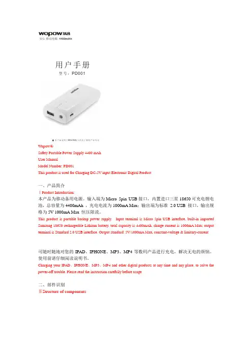
型号:PD001用户手册DC 5V 本产品适用于-输入的电子数码产品充电00mAh安心 移动电源 44Wopow ○R Safety Portable Power Supply 4400 mAhUser ManualModel Number: PD001This product is used for Charging DC-5V input Electronic Digital Product一、产品简介ⅠProduct Introduction:本产品为移动备用电源。
输入端为Micro 5pin USB 接口,内置进口三星18650可充电锂电池,总容量为4400mAh ,充电电流为1000mA Max ;输出端为标准 2.0 USB 接口,输出规格为5V 1000mA Max 恒压限流。
This product is portable backup power supply. Input termianl is Micro 5pin USB interface, built-in imported Samsung 18650 rechargeable Lithium battery, total capacity is 4400mAh, charge current is 1000mA Max; output terminal is Standard 2.0 USB interface. Output standard: 5V/1000mA Max, constant-voltage & limitary-current可随时随地对您的IPAD 、IPHONE 、MP3、MP4等数码产品进行充电,解决无电的烦恼。
使用前请仔细阅读说明书。
Charging your IPAD 、IPHONE 、MP3、MP4 and other digital products at any time and any place, to solve the power-off trouble. Please read the instruction carefully before usage二、部件识别ⅡStructure of componentsUSB 输出小电筒4档电量1. 4 level indicator light2. Power Indicator Light button3. LED flashlight4. USB output interface5. Micro Input Interface三、使用说明Ⅲ Usage instruction1.LED 小电筒使用:长按按键2秒,LED 小电筒打开;再长按按键2秒, LED 小电筒关闭.满电状态,使用LED 小电筒照明可长达100H 以上。
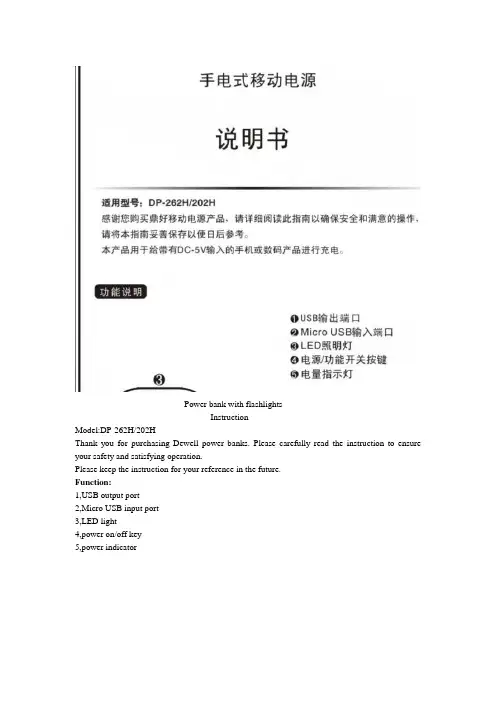
Power bank with flashlightsInstructionModel:DP-262H/202HThank you for purchasing Dewell power banks. Please carefully read the instruction to ensure your safety and satisfying operation.Please keep the instruction for your reference in the future.Function:1,USB output port2,Micro USB input port3,LED light4,power on/off key5,power indicatorTechnical specificationName : power bank with flashlightModel: DP-262H/DP-202HInput: 5V-1000mAOutput: USB5V-1000mAVolume: 105*47*31mmWeight: 156gCapacity range: 2600mAh*2/2000mAh*2Temperature range:Time to fully charge the cell: It costs 10 hours when in 5V--0.5AIt costs 8 hours when in 5V--1ARemark:1,Because of the conversion rate of the power bank, the real capacity of the power bank isn’t equal to the charging capacity.2, The specification and outer appearance of our product can change at anytime because of improvement.3, Power bank with flashlight all uses high capacity Li-ion cell, you can safely use it with its high quality.Instruction1,Please use the USB cable and charger that matches your phone or other digital products. (Remark: If you don’t use the cable or charger as the instruction indicated, we won’t take the responsibility for any possible deletion of the telephony information store, when you are using our power bank with flashlight.)2, To ensure the stability, please use the standard 5V1A charger.3, This product use Micro USb input port to charge itself and use the USB output port to charge the devices that is connected to the product.4,Electric energy will be consumed during charging/discharging. Slight heating is normal.5,Please store the product in a cool and day place. If it is not to be used in a long time, please fully charge the power bank once every six months.6,One Micro USB cable is attached inside. I t can charge oover 95%of the phones in the market. (Note: some products are not applicable.)Output interface Output current Applicable devices USB 1A Most mobile phones includingSamsung,HTC,Huawei,ZTE,Nokia, MOTO and full-seriesApple devices like iPhone,iPadand iPod or devices requringDC 5V o.5A-1A input.(Note:Samsung PPC and certainSamsung models requireexternal adapters beforeconnecting.)Instruction:1,Charge your power bankUse Micro USB cable to charge your power bank with flashlightUse computer to charge the power bank with flashlight 2 Charge your electronic devicesUse power bank with flashlight to charge your phoneUse power bank with flashlight to charge your tablet PC.Charge and discharge instructionFirst, Charge the built in battery of the power bank1,When the built in battery power is less than 25%, one of the light on the LED will flash, while the other three are still closed.2,25%《battery power <50%, the first light of the LED will open, while the second light will flash, and the rest remain closed.3,50%《battery power<70%;the first and the second light will open ,while the third will flash,and the rest remain closed.4,75%《battery power; the first three lights will open, the forth light will flash.5, when the built in battery is fully charged, all of the LED lights will open. Please stop charging.If in the course of charging, you connect your phone or digital products ,it will first charge your devices and the all of the LED lights will open. When your devices are fully charged, it will charge for the power bank itself and the LED lights display the built in battery power.Second, when in standby, the power bank will be in sleeping mode. When you connect your phone or digital products, the USB will automatically recognize and output. At this time, the power bank can charge your phone or digital products and the LED lights will display the rest power of the power bank.1, the rest power》75% , three of the LED lights will open, and the forth will flash.2,50%《the rest power<75%, two of the LED lights will open,while the third will flash, and the forth is closed.3,25%《the rest power<50%, the first LED light will open, while the second flashes and the rest are closed.4, the rest power<25%, the first LED light will flash, and the rest are closed.5, When all of the power are off, all the LED lights are closed and stop charging.(Note: The above number are only for you to refer)LED flashlight function instructionA, When in standby mode, long press the LED flashlight switch for 2 seconds, it will enter into strong light mode.1,press the button again,it will enter into flash exposure mode.2,Press the button again, it will enter into SOS mode.3,press the button again, the LED flashlight will close.B When the LED flashlight is at work, long pressing the switch button can directly close the LED flashlight.Customer service informationAbove are the malfunction and methods to resolve the malfunction. If the above operation can not resolve the product malfunction, please stop using the product immediately and contact the distributor or the Dewell official customer service line.TroubleshootingWhen the power bank malfunctions for some reason, you can resolve the malfuctions yourself. Fault content Failure prediction Trouble shootingCharging indicator Unqualified or incompatiblecharger is used for chargingPlease choose qualified,qualityassurance chargerMicro/USB input interfacepoor contact USB outputinterfacePlease check whether theinput/output interface is ingood connection Unqualified or incompatiblecable is used for chargingPlease use the attached ororiginal cableCharging is not automatically identified Built-in circuit protectiondosen’t match the active cable1,please original cable tocharge.2,first connect the power bankthen connect the phoneheat The battery itself will slightlyheat up when at work Please pay attention to whether the power bank is working at normal environmentThe lifetime of the power bank is too short The service life of the battery isto endPlease replace the power bank,if it cannot work any more.Precautions*please keep the product in a cool and dry place*please do not touch the product when your body is wet.*please don’t place the product in high temperature or high humidity or exposure to direct sunlight.*Please don’t place the product on the carpet, heater, fabrics or expose it in the direct sunlight. *Please keep the charging temperature around .*Please do not put the product on combustible material*It may explode if you remove or disassemble the built in battery.*Please do not put the product in the fire, river or corrosive liquid.*Please do not smash, squeeze of disassemble the product yourself.*If the product is found to have swelling or other malfunctions, please immediately stop using it and contact your dealer.*Unless there are professionals supervising or instructing, the following people are not supposed to use the product: people in degradation of mind or body, people who know little about the product. Please supervise children to ensure safety.Guarantee cardWarranty period:12months (it starts when the day you buy the product)Free service:During the warranty period, for all malfunction caused by the quality of the product itself, the customer can contact the dealer and enjoy free repair.The following situations cannot enjoy free repair:1,Damage caused by dis-assembly of yourself2,No guarantee card or the label has been damaged3,Damage caused by force majeure4,Damage caused by falling into water or man-made mechanical damageCustomer nameaddressProduct modeldealerTel:Product namePurchasing date。

WelcomeThank you for purchasing the mophie powerstation mini, powerstation, powerstation XL or powerstation XXL battery. Your powerstation battery is a compact yet powerful mobile charging solution for your tablet, smartphone, wearables and other USB devices. Now you will be able to travel great distances and be the master of your own destiny, no longer bound by the limitations of your device’s internal battery! Package Contains• powerstation mini, powerstation, powerstation XL or powerstation XXL portable battery• USB-A to USB-C cable• Quick-start guideFeaturesHere’s a rundown of why your powerstation mini, powerstation, powerstation XL or powerstation XXL battery is so great:• High-density, high-output portable battery charges devices at fast speeds—up to 3 ampsvia the USB-C port (up to 2.4 amps for thepowerstation mini).• Additional USB-A output ports let you charge multiple devices at the same time.• USB-C input/output port recharges the portable battery at fast speeds—up to 3A with acompatible wall adapter (up to 2.4 amps for thepowerstation mini).• Track battery power at a glance with the integrated four-light LED status indicator. Youcan keep tabs on charging status and currentbattery life. Know before you go!• mophie’s smart adaptive charging technology identifies your connected device and alwaysdelivers the fastest, most efficient chargingspeeds available.• Digital Power Management circuitry provides built-in short-circuit, overcharge and temperatureprotection. Safety first!CompatibilityThe mophie powerstation mini, powerstation, powerstation XL and powerstation XXL batteries are designed to work with most popular USB devices and wearables.• If you experience any issues with charging your device, ensure that the powerstation batteryis fully charged and check the FAQ section onthis website.No matter what device you have, carefully read through the Warning section in this manual and in the quick-start guide included with your battery before using it.Charging your powerstation battery IMPORTANT: Before using your powerstation mini, powerstation, powerstation XL or powerstation XXL battery for the first time, fully charge it (so that pressing the charge status button lights all four status LEDs).To charge your battery, use the supplied cable to connect the battery’s USB-C input/output port to a power source with a USB output, such as the wall adapter included with your smartphone or other device.powerstation mini;powerstation:powerstation XL;XXL:powerstationCharging your deviceConnect the cable that came with your device to one of the powerstation mini, powerstation, powerstation XL or powerstation XXL battery’s ports and to your device. All of the battery’s ports are available simultaneously, so you can charge multiple devices at the same time. Press the status button for 3 seconds to begin charging.powerstation mini;powerstation:If you have USB-C devices, connect them to the powerstation, powerstation XL or powerstation XXL battery’s USB-C connector for faster charging (up to 3 amps).Priority+ chargingWhen you’re recharging your powerstation mini, powerstation, powerstation XL or powerstation XXLpowerstation XL; powerstationXXL:battery, Priority+ charging provides power to a connected device first before the battery starts to recharge. Priority+ charging is available at the USB-A port that is marked with the following icon:powerstation mini; powerstation :powerstation XL; powerstation XXL:Checking your battery’s charging statusPress the status button on your powerstation mini, powerstation, powerstation XL or powerstation XXL battery and the status LEDs will indicate its charge level. Four LEDs means that the battery is fully charged, while one LED means that it’s almost empty. Know before you go!Taking care of your powerstation battery• Keep your battery dry and away from moisture and corrosive materials.• Do not clean your battery with harsh chemicals, soaps or detergents. Just wipe the case with asoft, water-dampened cloth.• Make sure the battery’s charging ports do not become contaminated with lint or other debris.Use a canned-air type of product periodically toensure that the port openings are clear.• Recharge your battery once every three months when not in use. If you plan on putting it away,fully charge it first (so that pressing the statusbutton lights all four charge status LEDs). WarrantyAt mophie, we are dedicated to making the best quality products. To back this up, this product is warranted for 2 years. For full details regarding warranty terms and exclusions, please visit: /warranty. This warranty does not affect any statutory rights that you may be entitled to. Keep a copy of your purchase receipt as proof of purchase. Be sure to register your product at .Exclusions & LimitationsExcept for the limited warranty expressly set forth or to the extent restricted or prohibited by applicable law, mophie expressly disclaims any and all other warranties express or implied, including any warranty of quality, merchantability, or fitness for a particular purpose, and you specifically agree that mophie shall not be liable for any special, incidental, indirect, punitive, or consequential damages for breach of any warranty of any type on any mophie product. In addition to and without limiting the generality of the foregoing disclaimers, the limited warranty does not, under any circumstances, cover the replacement or cost of any electronic deviceor personal property inside or outside of the mophie product.You may have additional warranty rights depending on your country, state, or province. Further, some countries, states, and provinces do not allow the exclusion or limitation of incidental or consequential damages or exclusions or limitations on the duration of implied warranties, so the above may not apply to you. If any provision of the warranty is found unlawful, void, or unenforceable, that provision shall be deemed severable and shall not affect any remaining provision.Customer ServiceTelephone: 1-888-8mophie (1-888-866-7443) International: +1 (269) 743-1340Web: /csIMPORTANT SAFETY INSTRUCTIONSWarningRead all instructions and warnings prior to using this product. Improper use of this product may result in product damage, excess heat, toxic fumes, fire or explosion, for which damages you (“Purchaser”), and not mophie llc (“Manufacturer”) are responsible.N Before using your powerstation battery for the first time, fully charge it (so that pressing thecharge status button lights all 4 status LEDs).N Do not store device in high-temperature environment, including heat caused by intense sunlight or other forms of heat. Do notplace device in fire or other excessively hotenvironments. Exposure to fire or temperatureabove 212°F (100°C) may cause explosion.N This product should be operated only in open-air conditions. It should not be operated in anenclosed, unventilated space such as a carryingbag, pocket, purse or bedding. Failure to followthese instructions may damage the productby overheating.N Be cautious of drops, bumps, abrasions, or other impacts to this product. If there is any damageto the product such as dents, punctures, tears,deformities, or corrosion due to any cause,discontinue use. Contact Manufacturer or dispose of it in an appropriate manner at yourlocal battery-recycling center.N Do not expose the portable battery to rain or snow.N Do not use the portable battery in excess of its output rating. Overloading outputs aboverating may result in a risk of fire or injuryto persons.N Do not disassemble this product or attempt to re-purpose or modify it in any manner.N Do not attempt to replace any part of this device. N For questions or instructions for the various ways to charge this device, refer to the Charging yourpowerstation battery section of this user manual. N Use of a power supply or charger not recommended by mophie may result in a risk offire or injury to persons.N If this device is accessible to or may be used by a minor, purchasing adult agrees to besolely responsible for providing supervision,instruction, and warnings. Purchaser agreesto defend, indemnify, and hold Manufacturerharmless for any claims or damages arisingfrom unintended use or misuse by a minor.N All products have gone through a thorough quality assurance inspection. If you find thatyour device is excessively hot, is emitting odor,is deformed, abraded, cut, or is experiencingor demonstrating an abnormal phenomenon,immediately stop all product use and contact Manufacturer.N Never dispose of batteries in the garbage.Disposal of batteries in the garbage is unlawfulunder state and federal environmental laws andregulations. Always take used batteries to yourlocal battery-recycling center.N Switch off the portable battery when not in use.The portable battery will automatically switchoff when disconnected from a device.LegalThis product is meant for use only in conjunction with the appropriate device. Please consult your device packaging to determine whether this product is compatible with your particular device. Manufacturer is not responsible for any damages to any device incurred through the use of this product. Manufacturer shall not in any way be liable to you or to any third party for any damages you or any third party may suffer as a result of use, intended or unintended, or misuse of this product in conjunction with any device or accessory other than the appropriate device for which this product is designed. Manufacturer will not be responsible for any damages you or any third party may suffer as a result of misuse of this product as outlined above. If you are responsible for product use with an unintended device and damages result from such use, you agree to indemnify Manufacturer for any resulting injuries to any third part(ies).mophie, powerstation, Priority+, Stay Powerful, mophie loves you, the five-circles design, and the mophie logo are trademarks of mophie inc.Lightning is a trademark of Apple Inc. USB-C is a trademark of USB Implementers Forum. All rights reserved. Patents: /patents.This device complies with part 15 of the FCC Rules and RSS-Gen of IC Rules. Operation is subject to the following two conditions: (1) This device may not cause harmful interference, and (2) this device must accept any interference received, including interference that may cause undesired operation. NOTE: This equipment has been tested and found to comply with the limits for a Class B digital device, pursuant to part 15 of the FCC Rules. These limits are designed to provide reasonable protection against harmful interference in a residential installation. This equipment generates, uses, and can radiate radio frequency energy and, if not installed and used in accordance with the instructions, may cause harmful interference to radio communications. However, there is no guarantee that interference will not occur in a particular installation.If this equipment does cause harmful interference to radio or television reception, which can be determined by turning the equipment off and on, the user is encouraged to try to correct the interference by one or more of the following measures:• Reorient or relocate the receiving antenna.• Increase the separation between the equipment and receiver.• Connect the equipment into an outlet on a circuit different from that to which the receiveris connected.• Consult the dealer or an experienced technician for help.CAUTION: To comply with the limits of the Class B digital device, pursuant to Part 15 of the FCC Rules, this device must be used with certified peripherals and shielded cables. All peripherals must be shielded and grounded. Operation with non-certified peripherals or non-shielded cables may result in interference to radio or reception. MODIFICATION: Any changes or modifications of this device could void the warranty.WEEE DECLARATION:All of our products are marked with the WEEE symbol; this indicates that this product must NOT be disposed of with other waste. Instead it is the user’s responsibility to dispose of their waste electricaland electronic equipment by handing it over to an approved re-processor, or by returning it to mophie, inc. for reprocessing. For more information about where you can send your waste equipment for recycling, please contact mophie, inc. or one of your local distributors.THIS DEVICE CONFORMS TO UL STD. 60950-1. CERTIFIED TO CSA STD. C22.2 NO. 60950-1. CONFORMS TO UL SUBJECT STD. 2056.。
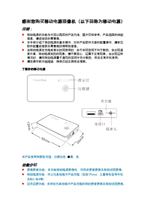
感谢您购买移动电源摄像机(以下简称为移动电源)说明:●移动电源的功能与外观以购买的产品为准,图片仅供参考。
产品选择的详细信息,请咨询您的零售商。
●本手册介绍了移动电源的基本操作,对本产品软件方面的配置操作,请参见软件配置或者联系零售商获得帮助信息。
●当移动电源在充电或者长时间使用时,由于封闭空间不利于散热,会出现温度升高,移动电源发热的现象。
请不要担心,这属于正常现象。
当出现这种情况时,请将移动电源置于通风的空间中充分散热,然后正常开机使用。
●请在操作前仔细阅读,确保已经正确完全理解。
了解你的移动电源本产品有两种颜色可选:◎银白色●黑色功能介绍●录像录音功能:多功能移动电源录像机,可同步录音录像及移动侦测录像。
●移动电源功能:可以为其他电子产品充电(包括iPhone,三星等各型号手机及Mp3,Mp4等)●边充边录功能:支持在为其他电子产品充电的同时录音录像及移动侦测录像。
特点:●隐蔽性很强●一键操作简单方便●大容量电池支持长时间录像●HD 720p和H.264压缩,节省内存●方便携带,也可做家庭安防使用●支持移动侦测录像及边为其他产品充电边录像安装Micro SD卡和镜面按照图示方向将有芯片的一侧朝左下方,将内存卡放在入口处,然后滑入卡槽内存卡安装完毕后开机录像测试工作正常后,将外壳的后镜面粘贴上去。
体验您的移动电源1.修改时间●首先关机●将设备用USB线连接到电脑●在我的电脑里打开可移动磁盘(TF卡)●创建txt文件并命名为time.txt●按照下面格式修改时间:2013.01.01 01:01:01●保存并退出●与电脑断开,开机完成设定2.开机长按功能键3秒钟直至红灯亮后松手3.录像红灯亮待机状态下短按功能键一次红灯闪2次并熄灭开始录像4.保存录像在录像状态下短按功能键一次,红灯亮保存录像并进入待机模式5.移动侦测模式在待机模式下长按功能键3秒钟松手,此时蓝灯闪2次熄灭,同时红灯也会熄灭进入移动侦测模式。

ENTINO™英迪诺100S锂离子备用电源产品说明书适用型号 ENTINO 100S英迪诺100S技术参数额定输出电压:5V(DC)额定输出电流: 2.1A(DC)最大输出电流: 2.3A(DC)额定电池容量:≥10000mAh充电输入电压:5V(DC)充电输入电流:0.7A(DC)完整充电时间:≤22h整机静态功耗:≤15μA循环工作寿命:>1200工作温度范围:-25℃~45℃配用电池类型:镍钴锰三元正极体系聚合物锂离子电池整机重量:≤?配用充电电源:计算机USB接口;输出电压为5V,输出电流大于0.7A的手机、平板电脑、数码相机等设备配用的充电适配器。
英迪诺100S产品装箱单1.英迪诺100S备用电源1台2.充放电连接线缆1条3.产品说明书1本4.产品检验合格证1张12英迪诺100S 技术特点1. 英迪诺100S 采用高压实密度镍钴锰三元正极锂离子电池,具有循环工作寿命长、无记忆效应、安全性好、比能量高等优点;2. 英迪诺100S 设有锂离子电池过放电保护、过充电保护、过温保护、输出过载保护电路,对锂离子电池提供完善的工作保护;3. 英迪诺100S 的最大稳压输出电流可达2.3A ,可用于对ipad 等配置大容量锂离子电池的用电装置快速充电;4. 英迪诺100S 的DC-DC 变换工作效率最高可达90%,可有效降低放电工作损耗、节能环保;5. 英迪诺100S 的静态功耗小于15微安,相当于在静置存储状态每天仅消耗电池电量的0.004%。
英迪诺100S 操控及显示装置英迪诺100S可用作为iphone ,ipad, ipod系列产品及市面所售几乎全部手机、平板电脑、数码相机、无线座机、MP3、MP4等数码电子产品的充电电源。
英迪诺100S可用于对满足下列充电适配条件的设备充电:充电电压:5V(DC)充电电流:≤2.3A(DC)1.英迪诺100S与被充电设备连接使用英迪诺100S为手机、平板电脑等产品充电时,将被充电设备配用3的充电线缆的USB插头插入英迪诺100S的电能输出接口,另一端连接被充电设备的充电接口。
产品说明书便携式充电宝使用说明产品说明书 - 便携式充电宝使用说明首部分:产品概述本产品是一款便携式充电宝,为用户提供便捷、高效且可靠的移动设备充电解决方案。
本说明书将详细介绍产品的特性、使用方法以及注意事项。
第一部分:产品特性1.1 充电容量本充电宝内置高性能锂电池,容量为XXXXmAh,能够满足用户全天候使用的充电需求。
1.2 多功能接口本产品配备多种接口,以满足不同设备的充电需求。
包括XXXX、XXXX等接口,用户只需携带一款充电宝即可同时为各种移动设备充电。
1.3 便携轻巧本充电宝采用轻量化设计,重量不超过XXX克,方便用户随身携带。
其紧凑的外形设计使其更易于放入口袋或背包中。
第二部分:使用方法2.1 充电前准备在使用本充电宝之前,请确保其已充满电或电量足够以供充电。
可以通过连接标准充电器或电脑USB接口进行充电。
2.2 连接设备将设备的充电线缆与充电宝相应的接口连接,确保连接牢固可靠。
2.3 开始充电连接完毕后,按下充电宝上的电源开关。
充电宝将开始为设备充电。
充电过程中,可以通过观察充电宝上的充电指示灯来判断充电状态。
2.4 充电完成与断电当设备充电完成后,可以通过断开充电线缆来停止充电。
此时,及时关闭充电宝上的电源开关,以节约电量和减少能源浪费。
第三部分:注意事项3.1 温度环境请避免将充电宝暴露在过高温度或极低温度的环境中,以免影响充电宝的性能和使用寿命。
3.2 防水防潮充电宝应避免与水或湿度过高的环境接触,以免导致设备失效或损坏。
3.3 防止过充与过放请注意不要将充电宝长时间连接电源进行充电,以防止电池过充。
同时,也要避免将充电宝完全耗尽电量,以免影响电池寿命和性能。
3.4 避免剧烈震动请避免将充电宝遭受剧烈震动或摔落,以免对其内部电路和电池造成损坏。
结尾部分:本产品为用户提供了一种快速、高效的移动设备充电解决方案。
通过阅读并按照本说明书正确使用充电宝,用户将获得更好的使用体验。
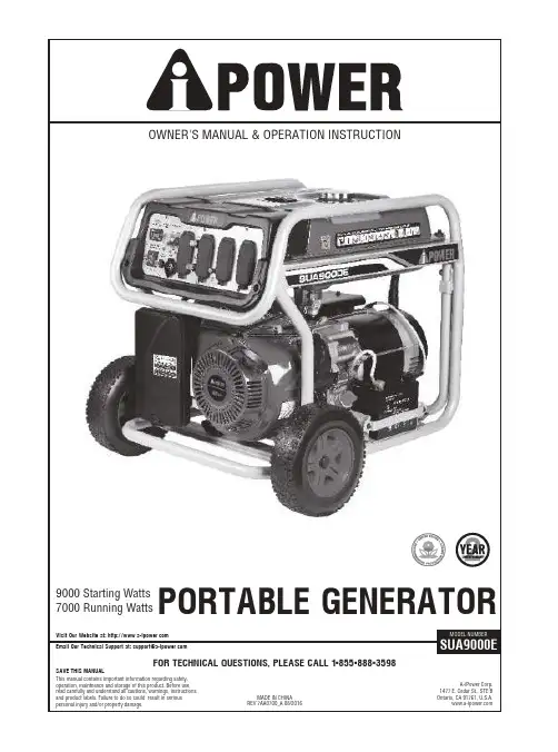
WARNINGThe Engine Exhaust from this product contains chemicals known to the State of California to cause cancer or birth defects and other reproductive harm.36791066999104.4Wattage Reference Guide10121212121516181920241313131313131414141415Parts list and Diagram2A-iPower.A-iPowerPlease call our Customer Service at 1-855-888-3598for starting, operating and servicing procedures. We also strongly recommend you to instruct any other users who may operate the generator in an emergency.Failure to followinstructions could result in serious injury or death.SECTION 1 SAFETY RULES34please call our Customer Service at 1-855-888-3598.5SECTION 2 SET UPINSTALL THE SUPPORT LEGINSTALL THE WHEEL KIT2.2.3 ADJUST SHOCK-ABSORBING SEAT(M8) 62- 9.5 in wheel2 -axle pin2- pin4- washer1- support leg2-flange bolt (M8x16) 2- nut (M8)1- engine oil 1.0 Quart 1- DC charge cable1- spark torch1- extension bar1- high altitude kitWheel kitSupport LegOtherThe above mentioned parts are packed in one box. Ensure you have all included items prior to assembly. If items are damaged or missing, call 1-855-888-3598.GENERATOR1. Fuel Tank - 7 gallon (25 L) capacity fuel tank.2. Choke Lever - Controls choke valve. Used when starting a cold engine.3. Air Filter - Protects the engine by filtering dust and debris from the intake air.4. Fuel Valve - Used to turn fuel supply on and off to engine.5. Recoil Starter - Used to manally start the engine.6. Oil Filler Cap - Check and fill engine oil level.7. Control Panel - See "Power Panel" section on Page 8.We are always working to improve our products. Therefore, final product may vary from images shown. A-iPower reserves the right to change features, specifications without notice for further improvements of products.75. Engine Switch - Set this switch to ON before starting engine. Set switch to OFF to shut off engine.1. Hour Meter - Monitor run time and schedule maintenance intervals 2. Low Oil Alarm - Alarm when low oil is detected8. GFCI 120V 20A 5-20R - Used to supply electrical power for the operation of 120V AC, 20A,single phase 60HZ electrical loads.4. 120V AC 30A L5-30R - Used to supply electrical power for the operation of 120V AC, 20A, single phase 60HZ electrical loads.10. 120/240 VAC 30A L14-30R Twist-lock Receptacle - Used to supply electrical power for theoperation of 120V AC and/or 240VAC, 30A, single phase 60Hz electrical loads.3. Circuit Breaker - The circuit breadker protects the generator against electrical overloads. The rating ofthe breaker and the load it protects are marked near the breaker. Should any of the Circuit Breakers trip, the generator will stop the electricity output. If this happens, unplug all loads from the generator. Allow the generator to cool down. Then, press the tripped Circuit Breaker, restart the engine, and re-attach loads.9. Ground Terminal - Prior to each use, set up the ground wire (not included) connection to theGrounding Terminal to properly ground the Generator.CONTROL PANEL138456279107. 12V DC OUTPUT – used for battery charging.6. DC Circuit Breaker –protect DC output, turn off automatically if the current exceeds 8A.8The SAE Viscosity Chart94.4 WATTAGE REFERENCE GUIDESTARTTurn Fuel Valve to ON position. 10startsPush the switch to “START” position, hold instart position until generator start.Caution: to prolong the life of starter components,DO NOT hold for more than 10 seconds. Pauseand retry as necessary. After generator starts,release switch and it will return to the “ON”position automatically.START11turnDO NOT overload Generator CapacityVolts x Amps = Watts:The “W A TTAGE REFERENCE GUIDE”on Page 10 helps to determine how many items the generator can operate at one time.EngineAt high altitudes over 3,000 feet, the engine carburetor and any other parts that control thefuel-air ratio will be affected, which will decrease performance, increase fuel consumption and increase emission. Proper operation can be ensured by installing an altitude kit by a qualified mechanic when use at altitude higher than 3,000 feet. Refer to the altitude kit and operation instruction (provided) when needed.HIGH ALTITUDE OPERATION12“MAINTENANCE”section13If running this unit under dirty or dusty conditions,or in extremely hot weather, to change the oil more often.CHANGING ENGINE OILSPARK PLUG MAINTENANCEAIR FILTER MAINTENANCEengine14Valve Clearance- Intake: 0.10-0.15mm(0.004-0.006 in)- Exhaust: 0.15-0.20mm(0.006-0.008 in)15ProblemPossible CausesProbable SolutionsEngine will not startFUEL RELATED:1.No fuel in tank or fuel valve is in “OFF” position.3.Choke not in START position, cold engine.2.Low quality, stale, dirty or deteriorated gasoline.4.Carburetor not primed.5.Dirty fuel passageways.6.Carburetor needle stuck.Fuel can be smelled in the air.7.Too much fuel in chamber. This can be causedby the carburetor needle sticking.9.Clogged Fuel Filter.FUEL RELATED:1.Fill fuel tank with fresh 87+ octane unleadedstabilizer-treated gasoline and turn fuel valve to “ON” position.Do not use gasoline with more than 10% ethanol (E15, E20, E85, etc.).3.Move Choke to START position.2.4.Pull on Starter Handle to prime.5.Clean out passageways using fuel additive.Heavy deposits may require further cleaning.6.Gently tap side of carburetor floatchamber with screwdriver handle.7.Turn Choke to RUN position. Removespark plug and pull the start handle several times to air out the chamber. Reinstallspark plug and set Choke to START position.9.Replace Fuel Filter.8.Intake valve stuck open or closed.8.Call customer servise: 1-855-888-3598.Drain fuel tank and carburetor; fill with freshfuel.IGNITION (SPARK) RELATED:1.Spark plug cap not connected securely.2.Spark plug electrode wet or dirty.3.Incorrect spark plug gap.4.Spark plug cap broken.5.Incorrect spark timing or faulty ignition system.IGNITION (SPARK) RELATED:1.Connect spark plug cap properly.2.Clean spark plug.3.Correct spark plug gap.4.Replace spark plug cap.5.Have qualified technician diagnose/repair ignition PRESSION RELATED:1.Cylinder not lubricated.Problem after long storage periods.2.Loose or broken spark plug.(Hissing noise will occur when trying to start.)3.Loose cylinder head or damaged head gasket. (Hissing noise will occur when trying to start.)4.Engine valves or tappets mis-adjusted or stuck.ENGINE OIL RELATED:1.Low engine oil.2.Engine mounted on slope,triggering low oil shutdown.COMPRESSION RELATED:1.Pour tablespoon of oil into spark plughole. Crank engine a few times and try to start again.2.Tighten spark plug.If that does not work, replace spark plug. If problem persists, may have head gasket problem, see #3.3.Tighten head.If that does not remedy problem, replace head gasket.4.Have qualified technician adjust/repair valves and tappets.ENGINE OIL RELATED:1.Fill engine oil to proper level.Check engine oil before EVERY use.2.Operate engine on level surface.Check engine oil level.Engine lacks powerEngine "hunts" or falters1.Carburetor is running too rich or too lean.2.Clogged or dirty fuel filter.1.Cylinder pressure is low. 1.Call Customer Service: 1-855-888-3598.2.Clean or replace fuel filter.1.Call Customer Service: 1-855-888-3598.2.Dirty air filter.2.Clean or replace fuel filter.16ProblemPossible CausesProbable SolutionsEngine misfires1.Spark plug cap loose.2.Incorrect spark plug gap or damaged spark plug.3.Defective spark plug cap.4.Old or low quality gasoline.5.Incorrect compression.1.Check wire connections.2.Re-gap or replace spark plug.3.Replace spark plug cap.e only fresh 87+ octane stabilizer-treatedunleaded gasoline.Do not use gasoline with more than 10% ethanol (E15, E20, E85, etc.).5.Diagnose and repair compression.(Use Engine will not start:COMPRESSION RELATED section.)Engine stops suddenly 1.Fuel tank empty or full of impure or low quality gasoline.2.Low oil shutdown.3.Defective fuel tank cap creating vacuum, preventing proper fuel flow.4.Faulty magneto.5.Disconnected or improperly connected spark plug cap.1.Fill fuel tank with fresh 87+ octane stabilizer-treated unleaded gasoline.Do not use gasoline with more than 10% ethanol (E15, E20, E85, etc.).2.Fill engine oil to proper level.Check engine oil before EVERY use.3.Test/replace fuel tank cap.4.Have qualified technician service magneto.5.Secure spark plug cap.Engine stops when under heavy load 1.Dirty air filter2.Engine running cold. 1.Clean or replace element.2.Allow engine to warm up priorto operating equipment.Engine knocks1.Old or low quality gasoline.2.Engine overloaded.3.Incorrect spark timing, deposit buildup,worn engine, or other mechanical problems.1.Fill fuel tank with fresh 87+ octane stabilizer-treated unleaded gasoline.Do not use gasoline with more than 10% ethanol (E15, E20, E85, etc.).2.Do not exceed equipment’s load rating.3.Have qualified technician diagnose and serviceEngine backfires1.Impure or low quality gasoline.2.Engine too cold.3.Intake valve stuck or overheated engine.4.Incorrect timing.1.Fill fuel tank with fresh 87+ octane stabilizer-treated unleaded gasoline.Do not use gasoline with more than 10% ethanol (E15, E20, E85, etc.)e cold weather fuel and oil additivesto prevent backfiring.3.Have qualified technician diagnoseand service engine.4.Check engine timing.Generator shuts down during operationNo AC outputGenerator gallops Repeated circuit breaker trippingGenerator cannot supply enough power or overheating 1. Out of fuel.2. Low oil level.1. Generator is overloaded.2. Insufficient ventilation.1. Cable not properly connected.2. Circuit breaker is open.3. Faulty brush assembly.4. Faulty AVR.5. Loose wiring.6. Other.1. Engine governor defective.1. Overload.2. Faulty cords or device.1. Fill fuel tank.2. Fill crankcase to the proper level. Place generator on a flat, level surface.1. Review load and adjust, see“xx”.2. Check for air restriction. Move to a well ventilated area.1. Check all connections.2. Reset circuit breaker.3. Replace brush assembly.4. Replace AVR.5. Inspect and tighten wiring connections.6. Contact Customer Service at 1-855-888-3598.1. Contact Customer Service at 1-855-888-3598.1. Review load and adjust. See“Wattage Reference Guide” on Page 10.2. Check for damaged, bare or frayed wires. Replace defective device.engine.1718SECTION 10 DIAGRAMS U A 9000E19SECTION 11 PARTS LIST AND DIAGRAM GENERAL PARTS LIST20GENERAL DIAGRAM21ENGINE PARTS LISTPart Discription Qty Part Discription Qty 1Bolt146Bearing2 2Cylinder Head Cover Assy147Crankshaft Assy1 3Exhaust Pipe148Gasket, Crankcase Cover1 4Gasket, Cylinder Cap149Dowel Pin2 5Bolt,Flange1250Crankcase Cover Assy1 6Air Deflector151Bolt,Flange7 7Regulating Nut, Rockshaft252Oil Seal2 8Rockshaft253Bearing1 9Rocker Arm254Dipstick1 10Bolt, Rockshaft255Bolt,Flange2 11Rotor, Exhaust Valve156Engine Oil Sensor1 12Spring Retainer, Exhaust Valve157Gestket, Rod1 13Spring Retainer, Intake Valve158Oil Seal1 14Valve Spring259Clip,Dowel Pin1 15Oil Shield160Regulating Gear Assy1 16Spring Retainer, Exhaust Valve261Washer, Plain1 17Plate, Push Rod Guide162Cam Shaft Assy1 18Cylinder Head Assy163Balance Shaft1 19Bolt,Stud,Intake264Rubber Seat1 20Gasket, Intake Valve165Clamp1 21Connector, Carburetor166Oil Alarming1 22Gasket, Carburetor167Adjusting Rod1 23Carburetor Assy168Regulating Control Assy1 24Gasket, Air Cleaner169Regulating Rocker Rod1 25Nut,Flange370Adjusting Spring1 26Clamp271Reset Spring1 27Fuel Tube0.4472Adjusting Arm1 28Protective Sleeve 173Starting Motor Assy1 29Bracket,Air Cleaner174Wire Cover1 30Air Cleaner Assy175Bolt,Flange2 31Bolt,Flange476Wire Pressing Plate1 32Bolt,Stud,Exhaust277Aluminum Gesket2 33Sparking Plug178Drain Bolt2 34Gasket, Cylinder Head179Charge Coil1 35Dowel Pin280Bolt,Flange2 36Push Rod281Ignition Coil Assy1 37Valve Lifter282Bolt,Flange2 38Intake Valve183Flywheel Assy1 39Exhaust Valve184Cooling Fan1 40Ring Set, Piston185Starting Cup1 41Piston186Nut,Flange1 42Clip, Piston Pin287Starter Assy, Recoil1 43Piston Pin188Clamp1 44Connector Rod Assy189Clamp1 45Crankcase Assy122ENGINE DIAGRAM231220162017 2425A-iPowerA-iPower's only liability shall be the repairor replacement of part(s) as stated above inno event shall A-iPower be liable for anyincidental or consequential damages.26A-iPower Limited Warranty PolicyThank You For Choosing A-iPower Generator!Our WarrantyA-iPower will, at its position, free of charge, repair or replace any part(s) which, upon examination, inspection and testing by A-iPower or an A-iPower authorized warranty service dealer that is defective in material or workmanship or both. Transportation charges on product submitted for repair or replacement under this warranty must be borne by purchaser. Retain your proof-of-purchase receipt. If you do not provide proof of the initial purchase date, the manufacturer’s shipping date of the product will be used to determine the warranty period starting. Customer is responsible for taking the unit to & from the “pre-approved” warranty center if there is an issue with the unit that needs mechanical work.Warranty TermAny new A-iPower generator purchased for non-commercial use from an authorized A-iPower generator dealer in the continental North America will be warranted against defects in material or workmanship for a period of one years, from date of purchase, subject to exclusions noted herein. The warranty period begins on the date of purchase by the first retail end-user, and continues for the period of warranty time. A-iPower customer service will keep on supplying spare parts per request after warranty period with cost charge. “Comsumer Use” means residential household using by a retail consumer. “Commercial Use” means all other uses, including used for commercial, industrial or business or rental purposes. Once equipment has experienced commercial use, it shall thereafter be considered as commercial use for purposes of this warranty. Warranty ExclusionsMost warranty repairs are handled routinely, but sometimes requests for warranty service may not be appropriate. This warranty will not cover the following:REGULAR WEARING: Outdoor Power Equipment, as with all mechanical devices, need periodic parts(s) service and replacement to perform as designed. This warranty will not cover repair when normal use has exhausted the lifetime of any part. INSTALLTION AND MAINTENANCE: This warranty does not cover the generator or its parts what have been subjected to improper or unauthorized accident, over-speeding, improper maintenance, repair or storage so as, in our judgment, to adversely affect its performance and reliability. This warranty also does not cover regular maintenance and parts such as air filters, adjustments, fuel system cleaning and obstruction (due to chemical, dirt, carbon lime, and so forth).OTHER: This warranty excludes wearing parts such as oil seal, etc. or malfunction resulting from accidents, abuse, modifications, alterations, or improper servicing or freezing or chemical deterioration; damaged related to rodent and/or insect infestation. This warranty excludes used, reconditioned and demonstration equipment, equipment used for prime power in place of utility power, equipment used in life support applications, and failures due to acts of God and other force majeure events beyond the manufacturers control, such as collision, theft, vandalism, riot or wars, nuclear holocaust, fire, freezing, lightning, earth-quake, windstorm, hail, volcanic eruption, water or flood, tornado or hurricane.How To Obtain Warranty ServicePleasecallourcustomerservicenumber1-855-888-3598,***************************************** support team at first in case of a service needed. Please prepare and provide the model number, serial number and the proof of purchase while contacting us or mail a request to:A-iPower Corp.1477 E. Cedar St. STE B, Ontario, CA 91761, U.S.A.27855-888-3598,626-225-8930。
HALO POWERGLOWThank you for choosing HALO. The HALO POWERGLOW is a portable charger with sophisticated motion sensor that lights up using illuminating white LED ring system. This is a perfect ashlight guide for inside any bag or backpack. The HALO POWERGLOW charges any USB compatible small electronic devices. Comes with strap and clip for easy attachment.Please read the operating instructions carefully before using the HALO POWERGLOW.CONTENTSIncluded ItemsOperating Instructions Maintenance and CareSafety PrecautionsSpeci cationsWarranty and Contact Information 1 3 4 5 6 81 | POWER YOUR LIFEINCLUDED ITEMS - HALO POWERGLOW - Micro-USB Cable - Operating InstructionsLOCATION OF CONTROLS 1 | Leather Strap/Carabiner 2 | Motion Sensor Light 3 | LED Battery Indicator Lights 4 | Power ON Button 5 | Micro-USB input port 6 | USB Output Port56124 | 2One solid lightTwo solid lightsThree solid lightsFour solid lights 0%-25%26%-50%51%-75%76%-100%First light blinking0%-25%26%-50%51%-75%76%-99%100% fully chargedIndicator Lights How to ReadAmount of Charge Indicator Lights How to ReadAmount of Charge HALO POWERGLOW POWER LEVEL INDICATORS HALO POWERGLOW POWER LEVEL INDICATORS:WHILE CHARGINGFirst light solid,second light blinkingFirst two lights solid,third light blinkingFirst three lights solid,fourth blinkingAll four lights solidOPERATING INSTRUCTIONSPrior to rst use, it is recommended to fully charge the HALO POWERGLOW.Press the Power ON Button to display the power level on the HALO POWERGLOW. The LED battery indicator will display four solid blue lights when fully charged.CHARGING THE HALO POWERGLOW Using the supplied Micro-USB cable, plug the micro-USB end of the cable into the micro-USB input port of the HALO POWERGLOW and plug the other USB connector into a computer or an AC adapter with a USB 5V output. CHARGING YOUR PERSONAL ELECTRONIC DEVICEUsing the Micro-USB cable, plug the standard end of the USB connector into the USB output port of the HALO POWERGLOW. You may also use your own USB cable that was supplied with your personal electronic device. The HALO POWERGLOW will automatically begin charging your electronic device. TURNING ON/OFF YOURHALO POWERGLOWThe HALO POWERGLOW will automatically turn on and begin charging as soon as it is plugged into your personal electronic device. To preserve the battery, the HALO POWERGLOW will automatically turn o if the electronic device is fully charged and no longer drawing power. When the HALO POWERGLOW 3 | POWER YOUR LIFEis manually unplugged from your device it will automatically turn o after 25 seconds.MOTION SENSOR LIGHT OPERATION The HALO POWERGLOW will light up when motion is detected within 5 inches. Simply reaching past the HALO POWERGLOW or hovering above the HALO POWERGLOW will activate the light. To preserve battery, the HALO POWERGLOW light will automatically turn o after 25 seconds.NOTE: Press the Power ON Button twice to disable the motion sensor lights. When the motion sensor lights are disabled, press the Power ON Button once to enable.MAINTENANCE AND CAREAfter prolonged use, the internal battery will become weak and the operation may become intermittent. When the battery is very low, the rst battery indicator will ash to alert you to recharge the internal battery as soon as possible.To maximize battery life: once the battery is fully discharged, immediately recharge (regardless of whether you plan to use this unit or not). If you do not plan to use the battery for an extended period of time (one week or longer), we recommend that you fully charge the battery. For longer periods of storage, please recharge the battery at least every two months to maintain the battery in optimum condition. | 4SAFETY PRECAUTIONSThis HALO POWERGLOW has been designed and manufac-tured to ensure your personal safety when used in the directed manner. Improper use can result in potential hazard.Please read all safety and operating instructions carefully before installation and use. Keep these instructions handy for future reference.- The HALO POWERGLOW should not be used near water or wet areas such as bathtubs, showers, bathrooms, sinks, swimming pools or basements.- To reduce the risk of re or electric shock, do not expose the HALO POWERGLOW to rain or moisture. Keep the HALO POWERGLOW away from dripping, splashing, or any objects lled with liquids. Do not place anything on HALO POWER-GLOW.- Keep away from heat sources, including but not limited to: open ame sources, radiators, stoves, ovens, cars, andampli ers that produce heat.- Do not expose HALO POWERGLOW or batteries to re or sunshine.- Do not puncture, crush or subject to mechanical shock.- Do not disassemble.- Unplug the charger when batteries are fully charged or not in use.- Li-ion batteries must be recycled. Do not dispose of in the trash.5 | POWER YOUR LIFESPECIFICATIONSModel: HPG-3000Battery Capacity: 3000mAhMicro USB Input: 5V 1AUSB Output: 5V 1ADimensions (W x H x D): 3.25 inches x 3.25 inches x .75 inches Weight: 102 gramsCharging Time: 1 hour 40 minutesWorking Temperature: 0ºF to 45ºF COMPLIANCE WITH FCC REGULATIONS “This device complies with Part 15 of the FCC Rules. Operation is subject to the following two conditions: (1) this device may not causeharmful interference, and (2) this device must accept any interference received, including interference that may cause undesired operation.”“Warning: Changes or modi cations to this unit not expressly approved by the party responsible for compliance could void the user’s authority to operate the equipment.”“NOTE: This equipment has been tested and found to comply with the limits for a Class B digital device, pursuant to Part 15 of the FCC Rules. These limits are designed to provide reasonable protection against harmful interference in a residential installation. This equipment generates, uses and can radiate radio frequency energy and, if not installed and used in accordance with the instructions, may cause harmful interference to radio communications. | 6However, there is no guarantee that interference will not occur in a particular installation. If this equipment does cause harmful interference to radio or television reception, which can be determined by turning the equipment o and on, the user is encouraged to try to correct the interference by one or more of the following measures:- Reorient or relocate the receiving antenna.- Increase the separation between the equipment and receiver. - Connect the equipment into an outlet on a circuit di erent from that to which the receiver is connected. Consult the dealer or an experienced radio/TV technician for help.LIMITED WARRANTYHalo International SEZC LTD warrants its products to be free from defects in material and workmanship under normal use. Conditions are as follows:- During the rst 90 days from date of purchase, Halo International SEZC LTD will repair or replace the defective product.- Halo International SEZC LTD will, subject to inspection, repair the defective product or replace it with a new or recondi-tioned unit. The return must be accompanied by a Return Merchandise Authorization (RMA) number to be issued upon request, and must be shipped prepaid. We do not o er shipping rebates at this time.- Warranty is void if the product has been improperly handled or misused in any way, or if the label and/or bar-coded warranty label has been removed or tampered with.- Where applicable, all requests for warranty returns must be accompanied by a proof of purchase.7 | POWER YOUR LIFE- The warranty does not extend to the electronic equipment that is used or which incorporates with any of our products and accessories.Halo International SEZC LTD shall not be held responsible for the improper use of its products.- For all questions or exchange requests, please call888-907-6274,*******************************This Limited Warranty sets forth the full scope of HALO’s obligations and liabilities with respect to the product. All implied warranties, including, without limitation, implied warranties of merchantability and tness for a particular purpose, are limited to the duration of this Limited Warranty. In no event shall HALO be liable for any incidental, special, consequential or punitive damages or any damages or losses of or to electronic equipment or products that are used with any of HALO’s products. | 8EMAIL US AT:OR888 907 6274。
RAVPower ®(睿能宝) FileHub多功能3000mAh移动电源(型号:RP- WD01 )-PC /笔记本电脑/平板电脑和智能手机与iOS和Android系统通用1、产品介绍感谢您购买本RAVPower ® RP- WD01 FileHub!5合1设计的RP- WD01 FileHub可以作为一个无线SD卡读卡器、一个USB存储媒体共享设备、NAS文件服务器、一个Wi-Fi热点和3000mAh的移动电源。
即可给Android智能手机和苹果手机充电,同时可扩大iPad,iPhone 及其他Android设备通过双向无线传输的存储(通过读取的SD卡,USB存储或外部硬盘的存储)。
其结构紧凑,多功能的设计将带给您前所未有的移动体验!1.1主要特点●无线SD卡读卡器和USB储存媒体共享设备允许您通过iPhone,iPad,安卓智能手机,平板电脑或电脑通过Wi- Fi连接(802.11 B / G / N)上读取SD卡或USB外接HDD / SDD的数据。
通过iPhone,iPad,智能手机,平板电脑或电脑的Wi- Fi连接(802.11 B / G / N )与RP- WD01之间实现双向数据传输。
iOS和Android移动应用程序在谷歌商店和苹果的iTune商店可下载安装。
通过搜索应用的功能来查找和定位特定的应用文件(如搜索:AIRstorwidisk)。
支持邮件发送照片或在社交网上和朋友分享。
●NAS文件服务器(Web界面)当你输入IP “10.10.10.254 ”通过FileHub可浏览器或读取并传输到外部存储设备中的数据。
应用程序使用NAS功能,可以读取你连接在FileHub外部存储设备上的数据。
●3000毫安移动电源/外置电池充电器备份电池应急充电。
可以为绝大多数数码设备充电。
根据个人所需,当被用作一个无线SD卡读卡器或者USB外部硬盘驱动器的读卡器的时候还可以给自己供应所需要的电力。
ENTINO ™Entino 锂离子备用电源产品说明书适用型号ENTINO EN-S100中国兵器工业集团1ENTINO EN-S100技术参数额定输出电压:5V (DC ) 额定输出电流:2.1A (DC ) 最大输出电流:2.3A (DC ) 额定电池容量:≥10000mAh 充电输入电压:5V (DC ) 充电输入电流:0.7A (DC ) 完整充电时间:≤22h 整机静态功耗:≤15μA 循环工作寿命:>1200次 工作温度范围:-25℃~55℃ 配用电池类型:聚合物锂离子电池 整机重量:≤400g 配用充电电源: 计算机USB 接口;输出电压为5V ,输出电流大于0.7A 的手机、平板电脑、数码相机等设备配用的充电适配器。
ENTINO EN-S100产品装箱单1. ENTINO EN-S100电源 1台2. 充放电连接线缆1条 3. 产品说明书1本 4. 产品检验合格证 1张ENTINO EN-S100技术特点1. ENTINO EN-S100采用高压实密度镍钴锰三元正极锂离子电池,具有循环工作寿命长、无记忆效应、安全性好、比能量高等优点;2. ENTINO EN-S100设有锂离子电池过放电保护、过充电保护、过温保护、输出过载保护电路,对锂离子电池提供完善的工作保护;3. ENTINO EN-S100的最大稳压输出电流可达2.3A ,可用于对ipad 等配置大容量锂离子电池的用电装置快速充电;4. ENTINO EN-S100的DC-DC 变换工作效率最高可达90%,有效降低放电工作损耗、节能环保;5. ENTINO EN-S100的静态功耗小于15微安,相当于在静置存储状态每天仅消耗电池电量的0.004%。
ENTINO EN-S100操作及显示装置3ENTINO EN-S100为其它设备充电ENTINO EN-S100可用作为iphone ,ipad, ipod 系列产品及市面所售几乎全部手机、平板电脑、数码相机、MP3、MP4等数码电子产品的充电电源。
USER MANUALThanks for choosing our device, which could charge the digital products with DC 5V input. Please read through this user manual carefully before you use this remarkable product.UNIT VIEW DESCRIPTION1. Turn on button2. Capacity indicators3. Input port4. Output port 15. Output port 2PRODUCT SPECIFICATIONWork for Mobile phone and digital productInput voltage DC5VInput current 1000 mAOutput voltage DC 5V-5.5VOutput current 1000 mACapacity 6600 mAhProduct weight 174.2gProduct dimension 97.2(L) x 62.1(W) x 22.1(H)mmOperating temperate -10℃-60℃Storage temperate -10℃-45℃HOW TO USE1. Simply using the attached USB cable to charge the digital product, One end of the USB cable connect with the "OUT" port of the power bank, another end connect with the digital product with converted tip or charging cable. Press the turn on button once, it will start to charge and the LED will flash.2. When the digital product is fully charged, disconnect your digital product from the power bank. When charging cable disconnected or fail to connect the digital product, the LED will stop flashing. And the power bank will turn off automatically after 30 seconds3. 30%70%100%is the three capacity indicator, when the 30% indicator light on means low power ,please charge the power bank in time4.Check the capacity by pressing and releasing the turn on button, the LED will be off within 30 second after the button is pressed.5.Pushing turn on button once more for a while once, the light is flashing. Pushing turn on button for while once again, the flashlight is switching off.Note:1. Because of the power conversion efficiency of the power bank and your digital devices, the rated capacity of the power bank is not equal to the actual chargeable capacity.2. This power bank could charge most of the digital devices, but there is still the chance that maybe some kind of devices or models could not be charged, this is the normal area and cannot be regarded as the defects.3. If the power bank could not charge your devices, then check if the cable is firmly connected, or if the right connector has been chosen. The original cable sold along with your devices is always suggested to use.4. If the instantaneous current is oversize when charging the digital devices, the power bank will turn to protected mode automatically. To relieve the protected mode by charging the power bank.HOW TO CHARGE THE POWER BANKThe "IN" port is the charging port of the power bank.The capacity indicator will flash when charging the power bank and the 100% indicator will light on after full charging. After disconnecting the cable, the LED will be off within 30 seconds..MAINTENANCEPlease read the below carefully. The misuse will damage the devices and lead to other anomalies. And we will not take the responsibility for those situations.1. The high quality or good brand cable and connectors are always suggested for charging.2. Recharge your power bank once every 3 months when it is not in use3. Keep the power bank away from fire or any extreme temperature or moist environment and corrosive material4. Keep the power bank out of the reach of children, the person without enough mental ability and the person without enough knowledge to use this product5. Never wash the power bank with any chemicals, soaps and detergents6. No Crash, do not open or puncture or hit or break the power bank, do not repair the power bank by yourself7. When you found the power bank or AC adapter/charger has any bad sign, such as expansion or blow up, etc. please stop using this power bank immediately.8. Please do not use in the combustible gas.9. Please do not use other methods or machines to charge this power bank关于公司历史和规模规模,我公司成立于2011年,经过4年的发展,公司的有员工150人,关于研发部门,我们共有10个人的研发团队,10人的QC控制队伍。
Guide of Easy-UseCatalogueProducts and components (1)Start to use (1)Installment of hardware (2)Installation and use of mobile App (3)Installation of video camera (6)Setting of Wi-Fi network (11)Point-to-point mode (13)FAQ (14)Products and components1.Camera2.Power adapter3.Installation stent4.Guide for quick start5.DiscStart to useInstallation of mobile App1. Download and install BVCam, download IOS in iphone store, search for Android system in GooglePlay. For convenience of installation, please scan the below two-dimension code to download BVCam installation. If your device can not be connected to GooglePlay, please scan the below APK two-dimension code for installation. Note: it is suggested to use the QR code Scanner self-contained by browser or from the third party to scan and download App, while direct downloading and installation of App file is not supported by the function of WeChat scanning.2. Clik “+” to add a new camera. Clik and add the networked camera to enter into the added page of camera, fill out UID or add camera. Note: when the camera is initially used, please set camera to connect wi th your router referring to the part “setting camera to connect WIFI network”in the instructions, then add camera3. Two methods for fast input of UID for camera: A, by scanning of two-dimensional code in camera, B, by searching camera in local area network.4. Filling in the name of camera and password of P2P .Default P2P password: 8888, click OK ifAdd device, add networked device Name UIDPasswordNew cameraNew cameraconfirmed. Successfully add camera. You are suggested to revise P2P visiting password for camera after camera is set.5. After displayed that camera is online, click camera which you just add to watch real time video, click at video interface, you can open the control disc of video.6. The icon and button of the pages in videoAdd device, add networked device NameUIDPassword6.Other functions on the pagesVideoScreenshotVideotapeAlarmingSet the camera1. Long press the list item for about three second or click the gear-like button to open the advanced configuration page of the camera.Video Screenshot Video recording Alarm2. Change the WIFI connection of the camera. Select “WIFI connection configuration”, the camera will display available Wi-Fi hotspot. Select the name of your Wi-Fi (SSID), enter the passwords of Wi-Fi, and then press “OK” to connect Wi-Fi. Note: after saving, if the camera has connected with WIFI, it will switch off the current connection and try to connect the new WIFI network, so that in App, the camera will be off-line temporarily for about 1 minute.4. SD card video-recording setting: set the mode of SD card video-recording and the frame size.5. Alarm configuration: Turn on or off motion detection alarm and set the interval time of alarm.Connect the camera with Wi-Fi networkIn case of a new camera or in case that your camera is installed at a new location, please reset the camera to factory settings (after the camera starts, press and hold the reset button for more than 5 seconds), AP mode is on after the camera is restarted, wifi indicator flashes slowly (every 3 seconds). And then open the setting of phone, connect the phone with AP hotspot of camera (WIFI network is named as camera UID), turn on APP until the phone is switched to WIFI network of camera.1.Connect the phone with AP hotspot of camera (WIFI network is named as cameraUID), turn on APP until the phone is switched to WIFI network of camera2.Choose “Add camera +” in App3.Chose “connect the camera with WIFI networkAdd device4. Scan QR code of camera UID, click “next”, and then confirm that the name of WIFI network displayed is right, enter the correct WIFI passwords and click “Start” to configure Wi-Fi.5. Wait until App prompts that Wi-Fi connection settings are completed and the camera is online, click “add a new camera” to add a cameraNotes: if APP always display failure, please check the following items:A. Before starting to configure Wifi, the indicator of camera does not flash slowly, AP isnot turned onB. The phone does not connect with AP of the camera, and it is necessary forconfiguration to connect your phone with AP hotspot of the cameraC. Support common router but do not support public router for which login pageauthentication is needed.D. During configuration, check whether the network name, passwords and UID areright.E. In current, Chinese Wifi name and passwords are not supported.F Do not support 5G Wifi signalG. Check whether Wifi indicator is always on, if yes, the camera is connected with thenetwork, please directly add online camera, App may not detect that the camera issuccessfully configured due to network mask.H. If WiFi is in WEP encryption mode, please change it to WPA mode.Watch a video in point-to-point modeIn case that there is no a Wifi router, you can directly watch a view and operate the camera in point-to-point mode.Steps:1. Reset the camera, turn on AP mode until the camera restarts,2. After starting the camera, find Wifi configuration page in your phone with the name same as Wifi network of camera UID, without passwords, which is not encrypted.3. Connect your phone with the Wifi network, wait for Wifi signal symbol which suggests that your phone is successfully connected.4 Slimmer to router mode, directly add online camera, and then it can be used normally. If the camera has been added, it can be added directly.5. Open and watch a video after successful connection.FAQ1. Why the search tool cannot find the camera?Answer: Please confirm that the network is normal, close the firewall and security software, ensure that the camera is connected with the router.2. Why the camera always ask for the user name and passwords, in other words, the use name is not right?Answer: The default passwords are 8888, if you forget the user name or passwords, you can reset the camera to factory settings to gain the default user and passwords.3. How can I recover the camera to the factory settings?Answer: Please press and hold the Reset button for about 5 seconds until the camera restarts.4. Why the image is not clear?Answer: Please remove the protective file of lens, if the question is not solved, please rotate the lens for focusing, and then the image will be clear.。
Compact Mobile2User manual(用户手册)1.Introduction 产品介绍2.Safety instructions 安全说明3.Controls and connections 调控和连接3.1 Front side 正面3.2 Rear side 背面4.Starting up 启动设备4.1 Cabling and switching-on 连线和开关4.2 Level adjustment 电平调节5. Functional characteristics 功能特征5.1 Equalization 均衡器5.2 Effects 效果器5.3 Footswitch 脚踏开关5.4 Phantom powering 幻象电源6.Technical specifications 技术规格7.Circuit diagram 电路图1.Introduction 产品介绍欢迎来到AER!感谢您使用Compact Mobile2。
Compact Mobile2是一套设计专业,小巧精致以及功能强大的扩音系统。
这是专为原声乐器扩音打造的扩音系统,同时也适用于电声乐器,人声,此外,你还可以为演出增加回放信号。
在不接入外部电源的情况下,Compact Mobile2的内部电池可供音箱持续工作4小时。
所有的AER音箱系统都能进行精准的动态控制,因此尽管音箱体积小、质量轻,但是仍可以保证音箱满载运行。
请按照说明书使用维护,并祝您使用愉快!2.Safety instructions安全说明下述的指导方针可以将音箱遭遇火灾或电击的风险性降到最低。
1.产品使用之前先仔细阅读这些安全说明!2.请将这份安全说明保存好。
3.请务必仔细阅读产品相关的警示信息,使用说明以及相关文字信息。
4.不要在近水处或者是双手沾水的时候安装或者使用音箱。
5.请在安全的地方使用该产品,确保没有人踩到电线或被绊倒以及损毁电线。
User GuideWebasto Go Mobile ChargerEnglishTable of ContentsTable of Contents1General information (3)1.1Purpose of this document (3)1.2Using this document (3)1.3Intended Use (3)1.4Use of symbols and highlighting (3)1.5Warranty and liability (3)2Important safety information (3)2.1General information (3)2.2General safety information (3)2.3High voltage warning (4)2.4Safety information (4)3Technical data (4)3.1Labels US (4)3.2Labels EU and UK (5)3.3Unit description (5)3.4Safety features (5)4Installation (6)5Using your Webasto Go Mobile Charger (6)5.1Indicator light (6)5.2Charging Your Vehicle (6)5.3Auto restart (7)6Care instructions (7)7Moving and Storage instructions (7)8Troubleshooting (8)8.1Troubleshooting (9)9Disposal (11)10Declaration of conformity (11)10.1FCC information (11)General information | 11General information1.1Purpose of this documentThis manual contains important instructions for the Webasto Go Mobile Charger that should be followed during installation, op-eration and maintenance of the product.NOTEIn addition to this document, follow and comply with local regulations and standards relating to operation,installation and environmental protection.1.2Using this documentuRead this document carefully before you install or use the Webasto Go Mobile Charger.u Keep these instructions for future reference.1.3Intended UseThe Webasto Go Mobile Charger is designed for charging elec-tric vehicles in accordance with IEC 62752, charge mode2. In this charge mode, the mobile charger ensures: The voltage is not applied before the vehicle has been connected correctly.The maximum power is calibrated. See also: https:///obp/ui/#iso:std:iec:62752:ed-1:v1:en:fig:E.1.1.4Use of symbols and highlightingNOTEThis symbol denotes a special technical feature, or (if 1.5Warranty and liabilityWebasto shall not assume liability for defects or damage that are the result of the installation and operating instructions being disregarded. This liability exclusion particularly applies for:l Improper use.l Repairs carried out by an electrician not contracted by Webasto.l Use of non-original spare parts.l Unauthorised conversion of the unit without permission from Webasto.l Installation and commissioning by unqualified staff (not an electrician).NOTEIn case of any claims, defects or damage to your pro-The symbol of a bin with a line through it means that the instructions in the chapter on Disposal must be fol-lowed.The Webasto Go Mobile Charger should not be oper-ated at altitudes of more than 13,123 ft. (4000 m)above sea level.2Important safety informationRead and comply with warnings in this User Guide.2.1General informationThe Webasto Go Mobile Charger is an easy-to-use, compact portable power supply for electric vehicle. The charger supplies and manages AC power to your electric vehicle and is compat-ible with a variety of battery electric vehicles and plug-in hy-brids.The charger operates from a 120 – 240 VAC (Single Phase) 50 –60 Hz power source.Key features:l Compact portable design l Overheating protection l Quick-read status indicatorsl Multiple adapters available for versatile usage in a variety of locationsl Overvoltage protection2.2General safety information3 | Technical data2.3High voltage warningNOTEDisconnect the charger from the wall socket before 2.4Safety information3Technical data3.1Labels USCCID Caution US Webasto1Technical specifications 2Information3WarningsTechnical data | 3 Product ID SAEFig. 2 Label Product ID SAE1Part number2Serial number3Manufacturing number3.2Labels EU and UKCCID Caution EU and UK Webasto1231Technical specifications2Light indicator3Address informationProduct ID IEC123 1Part number2Serial number 3Manufacturing number 3.3Unit description43121Type 1 IEC Coupler2Type 2 SAE Coupler3Low Power Adapter4High Power Adapter(North America)IEC(Europe)120 - 240 V AC230 V AC32 A max continuous32 A max continuous50 Hz< 2 W< 4 WApprox. 20 ft / 6.1 m Approx. 18.4 ft / 5.6m8.6 lbs / 3.9 kg9.2 lbs / 4.2 kg-22 °F to +122 °F-30 °C to + 50 °C-22 °F to +122 °F-30 °C to +50 °C-22 °F to +185 °F-30 °C to +85 °C-22 °F to +185 °F-30 °C to +85 °CNEMA 6 (watertight)IP67 (watertight)Not required Not required Specifications are subject to change without notice.Usable for Indoor and OutdoorThe Webasto Go Mobile Charger comes standard with two ad-apters:l One high power adapterl One low power adapterPlease refer to your vehicle owner’s manual for details on in-cluded and available adapters and accessories.3.4Safety featuresThe Webasto Go Mobile Charger is designed with your safety as the highest priority and includes the following safety features to protect against the risk of electric shock:l Service Ground Check: The charger constantly checks for the presence of a service ground connection. If the service ground ever fails, the charger RED Indicator turns ON andshuts down power to the vehicle.l Thermal Event Sensor: Charger module senses out-of-or-dinary thermal events and will decrease charging current or shut the unit down if required.l GFCI Protection: The Webasto Go Mobile Charger is equipped with a ground fault circuit interruption (GFCI) re-action system to protect against electric shock. If the char-4 | Installationger module detects an output ground fault, it will shutdown power to the output cable and illuminate the RED in-dicator.l Insulation: The charger module, adapter, cable assembly,and charge coupler are completely insulated (no exposed live parts) to protect against electric shock.l Unintentional Disconnection: The charge coupler is de-signed to minimize unintentional disconnection. A pilot sig-nal wire in the cable and charge coupler eliminates the pos-sibility of electric shock when not connected to a vehicle or if an unintended disconnect occurs during a charge. Dis-connection during charging is safe.4Installation11Wall hanger1.Choose a location to install the wall hanger.NOTEThe Webasto Go Mobile Charger can be used indoors and outdoors.NOTEThe hanger should be located in practical proximity toboth the utility receptacle or plug, and the location of your vehicle’s charge receptacle, preferably mounted to a wall stud.Drywall and masonry wall installations require the use of appropriate fasteners.2.Measure up approximately 8 inches / 20 cm from the de-sired receptacle and mark the location.NOTEBefore drilling any holes, verify that the control box will sit in hanger after it is plugged in.3.Drill out the preferred mounting holes through the back of the wall hanger using a 7/32 inch / 5.6 mm drill bit.4.Using a screwdriver, tighten the screws for the wall hanger.5Using your Webasto Go Mobile Charger1Indicator lightThe indicator light on your charger is the first thing you will no-tice when you are about to plug or unplug your vehicle. Before getting started, here is a simple explanation of the indicators.AMBER IndicatorThe AMBER Indicator illuminates to indicate the charger is re-booting after an error. Refer to the chapter 8.1, "Troubleshoot-ing" on page 9 for more information.BLUE IndicatorWhen plugged into the wall socket, the BLUE Indicator illumin-ates to indicate the charger is ready to use. During charging, the BLUE Indicator will pulse on and off every two seconds. Refer to the chapter 8.1, "Troubleshooting" on page 9 for more in-formation.RED IndicatorThe RED Indicator illuminates when the charger detects an er-ror. If the RED Indicator illuminates, the charger will not deliver power to the vehicle. The error must be corrected before a charging cycle can begin or continue. Refer to the chapter 8.1,"Troubleshooting" on page 9 for more information.5.2Charging Your Vehicle4312Type 2 SAE Coupler High Power AdapterNOTEIf Wall bracket is not used for mounting the cordset,plug cordset to wall socket closer to ground.Care instructions | 6NOTENote the following safety features chapter 3.4, "Safetyfeatures" on page 5.1.Make sure the vehicle is in park (P).2.Insert the adapter firmly into the control box.3.Firmly insert the other end of the adapter into the appropri-ate wall socket.NOTEYou will hear an audible “click” when the adapter iscorrectly inserted into the control box – make sure theadapter is fully inserted and flush with the control boxbefore inserting the other end into the wall socket. Oth-erwise, it will trigger a fault or cause a longer chargesession.4.When the wall plug is inserted:–The AMBER, BLUE and RED indicators will blink once.Then the BLUE Indicator turns ON, followed by a blink ofthe RED indicator. Lastly, the BLUE indicator turns OFF,then ON again. This cycle will happen twice if a differentadapter is used from previous charge.5.Plug the coupler into your vehicle’s charging inlet:–Type 1 Coupler: When coupler is fully inserted therewill be an audible clicking sound.–Type 2 Coupler: The coupler will lock in place once it isfully inserted.6.When charging begins:–The BLUE Indicator will pulse on and off approximatelyevery two seconds.7.When charging ends:–The BLUE Indicator will illuminate solid blue.8.To disconnect the coupler from the vehicle charge port:–Type 1 Coupler: Press the release button on thecoupler, then pull the coupler away from the vehicle.–Type 2 Coupler: Press the vehicle’s Cord Unlock But-ton, then pull the coupler way from the vehicle.NOTEWhen plugging the charger into an unfamiliar wallsocket, it is good practice to take few minutes to ob-serve the charging process and confirm it is supplyingthe expected AC charging power before leaving thecharger unattended.The RED Indicator will illuminate if it is not charging.The unit will turn OFF if a breaker or infrastructure GFIis tripped.NOTEFor more information about how to charge yourvehicle, including charge settings and scheduling, referto the vehicle owner’s manual.NOTEThe IC-CPD adaptor shall except if the adaptor is part ofthe IC-CPD and pluggable IC-CPD.The components of a pluggable IC-CPD must be discon-nected while the IC-CPD is in use (infrastructure or thevehicle connector is engaged in a vehicle inlet).The IC-CPDs shall be used in accordance with their in-structions.5.3Auto restartThe Auto-Restart feature helps to ensure that your vehicle willbe charged and ready for use when needed. A charge may beinterrupted if an error is detected. Charging will resume oncethe error is no longer detected. The RED Indicator illuminatesduring an error condition.The exception to immediate Auto-Restart is when the interrup-tion is due to a ground fault circuit interruption (CFCI). The char-ger will attempt to restart 15 minutes after this happens. After afourth attempt to restart, the charger will shut down and theRED Indicator will stay ON.If the fault persists, do not continue to try to charge yourvehicle. Contact your Webasto dealer.6Care instructionsDo not use hard cleaners or solvents as this may damage yourWebasto Go Mobile Charger. Do not kink or place undue stresson the charger cables. If the charger overheats, bring out of dir-ect sunlight.7Moving and StorageinstructionsIf improper moving or storage of the device is able to result indamage to the product that could result in a risk of fire or elec-tric shock during subsequent use, the instructions shall describethe proper moving and storage procedure, and shall be pre-ceded by the heading chapter 7, "Moving and Storage instruc-tions" on page 7 or the equivalent.Instructions for moving the device shall state that the device isnot to be lifted or carried by either the flexible cord or the EVcable, if provided. The appropriate means for carrying and mov-ing the device shall be described.Instructions for the proper storage of the device, including loca-tion, temperature limits, and the like, shall be provided in theMoving, Transporting and Storage Instructions.8 | Troubleshooting8TroubleshootingPlease refer to this Troubleshooting Guide for possible solutions to common errors or difficulties with charging your vehicle us-ing your mobile charger.NOTETroubleshootingIf you experience any troubles in the initial moment ofinstallation and operating the Webasto Go MobileCharger, please contact your contractual partner forsupport.NOTEDo not attempt to repair or service the charger yourself.There are no user serviceable parts inside this product.11Indicator lightA red indicator may be triggered by sources such as the charger, the utility service, and the vehicle. See chapter , "Troubleshoot-ing" on page 9. The red indicator turns on when the charger detects an error, whether it is connected to your vehicle or not. If the red indicator is on, then the charger will not deliver power to the vehicle. Correct the error for charging to begins or re-sume.Troubleshooting | 8 8.1Troubleshooting8 | TroubleshootingDisposal | 95911743-A-01 Webasto Go 11 / 129DisposalThe symbol of the crossed-out waste bin indicates that this electrical/electronic device must not be disposed of in household waste at the end of its service life. Dispose of the device free of charge at a local collection point for electrical/electronic devices. Addresses can be obtained from your city or local authority. Separate collection of electrical and electronic devices enables re-use, material re-cycling or other forms of re-utilization of waste equipment while also avoiding the negative effects of hazardous substances which may be contained in the devices on the environment and for human health.l Dispose of packaging in corresponding recycling container in accordance with national regulations.Austria:The EAG-VO ordinance in Austria incorporated EU law on waste electronic and electrical equipment into national legislation. This ordinance ensures that private households have the opportunity to return waste electronic and electrical equipment (WEEE) to public collection points free of charge. It is no longer permitted to dispose of WEEE in mixed municipal waste; instead, these must be handed in at the designated collection points. This al-lows functioning equipment to be reused, or valuable constitu-ent parts of broken equipment to be recycled. The aim of this is to contribute to more efficient use of resources and more sus-tainable development. Moreover, it is only through separate col-lection that hazardous elements of the equipment (such as CFCs or mercury) can undergo sufficient treatment, thereby avoiding negative impacts on the environment and human health. There are municipal and manufacturer systems available for return and collection of your waste household equipment free of charge.An overview of available collection points can be found on the following website: https://secure.umweltbundesamt.at/eras/registerabfrageEAGSammelstelleSearch.do . All household electronic and electrical equipment is marked with the symbol of a crossed-out wheeled bin. This equipment may be handed in at any collection point listed under the above link, and should not be disposed of with household waste.10Declaration of conformityThe Webasto Go Mobile Charger was developed, manufactured,tested and supplied in accordance with the relevant directives,regulations and standards for safety, EMC and environmental compatibility.Webasto Thermo & Comfort SE hereby declares that the"Webasto Go Mobile Charger" is in compliance with Directive 2014/35/EU.The full text of the EU declaration of conformity can be found at the following web address:https:///int/products/documentation10.1FCC informationThis device complies with Part 15 of the FCC Rules. Operation is subject to the following conditions:l This device may not cause harmful interference.l This device must accept any interference received, including interference that may cause undesired operation.This product has been designed to protect against Radio Fre-quency Interference (RFI). However, there are some instances where high-powered radio signals or nearby Radio Frequency (RF) producing equipment could affect operation.If you suspect your charger is receiving interference, take the following steps before contacting Customer Support for service:https:///en-int 1.Relocate away from electrical appliances or equipment dur-ing charging.2.Turn off nearby electrical appliances or equipment duringcharging.NOTEChanges or modifications to this product by anyone other than an authorized service provider will void FCC compliance and the product will not be serviceable.I d e n t N o . 5911743-A -01 • 07/2022 • E r r o r s a n d o m i s s i o n s e x c e p t e d • © W e b a s t o C h a r g i n g S y s t e m , I n c .To request this Installation Documentation in another language, please locate and contact your local Webasto dealer.You can find your nearest dealer at: https:///en-int.To provide feedback (in English or German) on this document, please email the Tech Doc and Translation team: feed-********************USA:Webasto Charging Systems, Inc.1333 S. Mayflower Ave.Monrovia, CA 91016USATel: +1 (888) 833-2148*****************Corporate headquarters:Friedrichshafener Str. 982205 Gilching GermanyUK only:Webasto Thermo & Comfort UK Ltd Webasto House White Rose Way Doncaster Carr South Yorkshire DN4 5JHUnited Kingdom。
Power bank with flashlightsInstructionModel:DP-262H/202HThank you for purchasing Dewell power banks. Please carefully read the instruction to ensure your safety and satisfying operation.Please keep the instruction for your reference in the future.Function:1,USB output port2,Micro USB input port3,LED light4,power on/off key5,power indicatorTechnical specificationName : power bank with flashlightModel: DP-262H/DP-202HInput: 5V-1000mAOutput: USB5V-1000mAVolume: 105*47*31mmWeight: 156gCapacity range: 2600mAh*2/2000mAh*2Temperature range:Time to fully charge the cell: It costs 10 hours when in 5V--0.5AIt costs 8 hours when in 5V--1ARemark:1,Because of the conversion rate of the power bank, the real capacity of the power bank isn’t equal to the charging capacity.2, The specification and outer appearance of our product can change at anytime because of improvement.3, Power bank with flashlight all uses high capacity Li-ion cell, you can safely use it with its high quality.Instruction1,Please use the USB cable and charger that matches your phone or other digital products. (Remark: If you don’t use the cable or charger as the instruction indicated, we won’t take the responsibility for any possible deletion of the telephony information store, when you are using our power bank with flashlight.)2, To ensure the stability, please use the standard 5V1A charger.3, This product use Micro USb input port to charge itself and use the USB output port to charge the devices that is connected to the product.4,Electric energy will be consumed during charging/discharging. Slight heating is normal.5,Please store the product in a cool and day place. If it is not to be used in a long time, please fully charge the power bank once every six months.6,One Micro USB cable is attached inside. I t can charge oover 95%of the phones in the market. (Note: some products are not applicable.)Output interface Output current Applicable devices USB 1A Most mobile phones includingSamsung,HTC,Huawei,ZTE,Nokia, MOTO and full-seriesApple devices like iPhone,iPadand iPod or devices requringDC 5V o.5A-1A input.(Note:Samsung PPC and certainSamsung models requireexternal adapters beforeconnecting.)Instruction:1,Charge your power bankUse Micro USB cable to charge your power bank with flashlightUse computer to charge the power bank with flashlight 2 Charge your electronic devicesUse power bank with flashlight to charge your phoneUse power bank with flashlight to charge your tablet PC.Charge and discharge instructionFirst, Charge the built in battery of the power bank1,When the built in battery power is less than 25%, one of the light on the LED will flash, while the other three are still closed.2,25%《battery power <50%, the first light of the LED will open, while the second light will flash, and the rest remain closed.3,50%《battery power<70%;the first and the second light will open ,while the third will flash,and the rest remain closed.4,75%《battery power; the first three lights will open, the forth light will flash.5, when the built in battery is fully charged, all of the LED lights will open. Please stop charging.If in the course of charging, you connect your phone or digital products ,it will first charge your devices and the all of the LED lights will open. When your devices are fully charged, it will charge for the power bank itself and the LED lights display the built in battery power.Second, when in standby, the power bank will be in sleeping mode. When you connect your phone or digital products, the USB will automatically recognize and output. At this time, the power bank can charge your phone or digital products and the LED lights will display the rest power of the power bank.1, the rest power》75% , three of the LED lights will open, and the forth will flash.2,50%《the rest power<75%, two of the LED lights will open,while the third will flash, and the forth is closed.3,25%《the rest power<50%, the first LED light will open, while the second flashes and the rest are closed.4, the rest power<25%, the first LED light will flash, and the rest are closed.5, When all of the power are off, all the LED lights are closed and stop charging.(Note: The above number are only for you to refer)LED flashlight function instructionA, When in standby mode, long press the LED flashlight switch for 2 seconds, it will enter into strong light mode.1,press the button again,it will enter into flash exposure mode.2,Press the button again, it will enter into SOS mode.3,press the button again, the LED flashlight will close.B When the LED flashlight is at work, long pressing the switch button can directly close the LED flashlight.Customer service informationAbove are the malfunction and methods to resolve the malfunction. If the above operation can not resolve the product malfunction, please stop using the product immediately and contact the distributor or the Dewell official customer service line.TroubleshootingWhen the power bank malfunctions for some reason, you can resolve the malfuctions yourself. Fault content Failure prediction Trouble shootingCharging indicator Unqualified or incompatiblecharger is used for chargingPlease choose qualified,qualityassurance chargerMicro/USB input interfacepoor contact USB outputinterfacePlease check whether theinput/output interface is ingood connection Unqualified or incompatiblecable is used for chargingPlease use the attached ororiginal cableCharging is not automatically identified Built-in circuit protectiondosen’t match the active cable1,please original cable tocharge.2,first connect the power bankthen connect the phoneheat The battery itself will slightlyheat up when at work Please pay attention to whether the power bank is working at normal environmentThe lifetime of the power bank is too short The service life of the battery isto endPlease replace the power bank,if it cannot work any more.Precautions*please keep the product in a cool and dry place*please do not touch the product when your body is wet.*please don’t place the product in high temperature or high humidity or exposure to direct sunlight.*Please don’t place the product on the carpet, heater, fabrics or expose it in the direct sunlight. *Please keep the charging temperature around .*Please do not put the product on combustible material*It may explode if you remove or disassemble the built in battery.*Please do not put the product in the fire, river or corrosive liquid.*Please do not smash, squeeze of disassemble the product yourself.*If the product is found to have swelling or other malfunctions, please immediately stop using it and contact your dealer.*Unless there are professionals supervising or instructing, the following people are not supposed to use the product: people in degradation of mind or body, people who know little about the product. Please supervise children to ensure safety.Guarantee cardWarranty period:12months (it starts when the day you buy the product)Free service:During the warranty period, for all malfunction caused by the quality of the product itself, the customer can contact the dealer and enjoy free repair.The following situations cannot enjoy free repair:1,Damage caused by dis-assembly of yourself2,No guarantee card or the label has been damaged3,Damage caused by force majeure4,Damage caused by falling into water or man-made mechanical damageCustomer nameaddressProduct modeldealerTel:Product namePurchasing date。