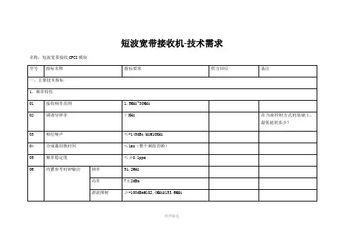
222-1 短波接收机使用说明书
- 格式:pdf
- 大小:15.50 MB
- 文档页数:80

SDR短波电台使用说明书:频率范围RX: 0.5MHz-30MHz发射: 所有业余无线电短波频段收发模式SSB(J3E),CW,AM(接收), FM, 数字语音滤波器可调范围500HZ-10KHZ输出功率1W-13W(最大)接收灵敏度0.11~0.89μV(RFC 50-20)最小步进1Hz电压范围DC9~15V内置电池容量12.6V 2200mah接收电流350mah内置驻波表显示精准内置电池携带方便内置USB声卡可以使用电脑的SDR软件通过USB口收发,使用FT817协议,支持WSJT-X数字通讯支持ACC口控制外接70-100W功放天线阻抗50Ω频率稳定度±1.5PPM 开机5分钟(标准) ; ±0.5PPM 打开温补功能最大电流3.5A尺寸(W ×H ×D)190mm*69mm*45mm重量980g配件有充电器手咪BNC转N头六角扳手2个固定架子收听广播步骤:接上天线,侧面开关拨到ON ,按住POWER1秒开机,按BNAD <> 选择3.X或者5.X开头频率,按MODE多次选择AM模式,按STEP选择下标1KHZ,旋转TUNE直到收到台,关机:长按Power关机,长时间不用,侧面开关打到OFF业余无线电对讲步骤:接上天线,机器旁侧面开关拨到ON ,按住POWER1秒开机,按BNAD <> 选择7.X或者14.X开头频率,按MODE多次选择USB或者LSB模式,按STEP移动位数,按TUNE调数字调到7.050或者14.270,留意是否有人讲话,按PA选择5W,手咪接到Mic插口,按手咪讲话,声音越大,指示表显示越大,功率越大,如果没反应,长按几次M3 选择MIC模式,注意SWR显示,3以下效率比较低,有条件的调整天线长度最佳为SWR<=1.5,关机:长按Power关机,长时间不用,侧面开关打到OFF3.电压低于9.9V自动关机,充电步骤,1:侧面开关打到OFF,2:充电器接上转接头接到小的供电口(Charge Only),充电器红灯亮,充满变绿灯(充电器只能给机器充电,不能接DC in工作)频率校准:频率调到10MHZ或者15MHZ,听到了类似对时的声音说明可以对时按MODE选择SAM模式,右上角会显示误差的频率,如果与当前频率相差5HZ以上说明偏差较大,旋转RIT修正右上角的频率到5HZ以内即可。

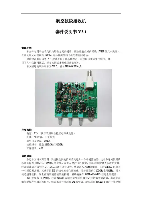
航空波段接收机套件说明书V3.1简单介绍本套件专用于接收飞机与塔台之间的通话,配合性能良好的天线(VHF段八木天线),开阔处最大可接收约190Km内各种类型的飞机与塔台间通话。
原始设计来自国外,“”对其进行了商品化改进,结合国内实际使用情况,修正了几个关键问题后,经多次调试才形成目前的版本。
本文描述的硬件版本为V3.0,板名HM00ABRA_3。
主要指标电源:12V(推荐采用线性稳压电源或电池)天线:50欧姆,不平衡式典型接收电流:30mA接收频率:覆盖118MHz-136MHz工作模式:AM电路原理参见本文档末页附图,天线接收到的信号首先进入一个带通滤波器,这个带通滤波器的功能是确保118MHz-136MHz的信号可以进入2SC3355高放,其他信号被最大程度的衰减。
经过滤波后的信号经Q1(2SC3355)进行放大,然后进入NE602混频,同时NE602内部有一个压控振荡器,其频率因D1的结电容变化而变化,设计覆盖约120MHz-150MHz,因本机是超外差机,加上前面带通滤波器的抑制,最终确保118MHz-136MHz信号全部覆盖。
本机中频为10.7MHz,经过NE602混频的信号送给10.7MHz的陶瓷滤波器,其功能是滤除混频产生的无关信号,然后把信号再送给Q2做中放,最后送给MC1350做进一步中频放大。
MC1350放大的信号,经中周T1选频后,送给D2进行调幅信号的包络检波。
检出来的音频信号经过U4A和U5B、LM386放大后再送给耳机输出。
其中,AGC功能由U4A和U4B配合完成,静噪功能由U5A、U5B配合完成。
元件选择所有小于1000pF 的电容为高频瓷片,大于1uF 的电容为铝电解电容,所有电阻为1/4W 5%固定电阻。
制作调试安装所有元件前先将所有的晶体管、电阻、电容用万用表测试一遍。
然后对照电路图和PCB板上的标识安装所有元件。
一般依从低到高的次序安装。
同时给集成电路安装插座,这样可以有效避免将核心的集成电路焊坏。
DSP-222 Operations ManualDual Channel InductiveLoop Detector Sensor UnitThis manual contains technical information for the DSP-222 detector sensor unit. Included are general description, general characteristics, installation procedure, adjustment instructions, operational guide, maintenance procedures and technical schematics and drawings.1. General DescriptionThe DSP-222 is a dual-channel inductive loop vehicle detector sensor unit designed to meet the State of California, Department of Transportation, (Caltrans) specification TSCES dated January of 1989 and the addendum dated July of 1991.2. General CharacteristicsThe sensor unit incorporates a double-sided 44-pin edge connector for the connection of power, loop inputs and call outputs and sensor unit reset. Each channel has individual front-panel controls for setting sensitivity, frequency, and pulse/presence mode. Each channel is also equipped with two high-intensity front-panel LEDs which are used to indicate the detect state and fail condition of the individual channels. Call outputs are optically isolated solid-state transistors. The sensor unit occupies one position of a standard 170 input file. Each channel of the DSP-222 will automatically tune to any loop and lead-in inductance between 50 and 750 microhenries with a loop system “Q” as low as 5. The unit will detect inductance changes as small as 0.01%L/L.3. Installation and AdjustmentsThe sensor unit is factory shipped with all switches set to off signifying both channels are disabled. The MIN PRESENCE jumper J1 located on the printed circuit board is installed forcing all detection outputs to last a minimum of 100 ms in the presence mode. The ALTERNATE jumper J2 located on the printed circuit board is installed forcing both channels to operate in the non-scanning mode.a) Remove the MIN PRESENCE jumper J1 on the circuit board to allow presence outputs of times less than 100 ms, if so desired.b) Remove the ALTERNATE jumper J2 on the circuit board to allow both channels to scan sequentially, if so desired.c) Make sure that the sensor unit is firmly seated into its position in the input file.d) Set the PULSE switch on for pulse operation. Set the PULSE switch off for presence operation.e) Adjust sensitivity by setting switches S1, S2, and S4 to the desired position using standard binary coding. Sensitivity 1 is the lowest setting and Sensitivity 7 is the highestsetting. If a channel is not used, it may be switched off (disabled) by setting it to Sensitivity 0 (all three switches off).f) Frequency setting needs to be changed only if crosstalk occurs between nearby loops. Crosstalk usually manifests itself as chattering of the call output. Change the frequency if crosstalk is encountered. Four frequency positions are available on each channel to assist in alleviating interference. It may be necessary to reset the channel after the frequency has been changed.g) Check the front-panel indicators. If the Fault LEDs on either channel are flashing there is a problem with the loop system on that channel. Observe the flash sequence to determine the type of fault. A single flash followed by a pause indicates an open loop system. A double flash indicates a shorted loop system. Check the loop connections carefully. Reset both channels by momentarily selecting a different sensitivity or mode and then return to the original setting.h) Monitor operation and make adjustments to the sensitivity and frequency as necessary.4. Theory of OperationThe DSP-222 works on the principle that loop frequency is directly related to loop inductance. However, the change in loop frequency is very small -- perhaps as little as one hertz. It is easy to measure a change of one hertz simply by counting the number of cycles in one second. Unfortunately, the minimum response time using this method is easily greater than one second. To improve the response time, the measurement is done by gating a high-speed stable oscillator with the loop frequency. This scheme, called period measurement, provides high-resolution in a short period of time. This measurement is compared to a previously established reference to determine whether or not the frequency of the loop oscillator has changed sufficiently to indicate the presence of a vehicle.The high speed of the reference crystal oscillator ensures that the sample can be taken within a very short period of time. For example, at sensitivities less than 4, a sample can be taken within 2 ms which allows the sensor unit to respond to a vehicle presence (or loss of presence) in the detection area with an accuracy of 1 ms. Note: This is true only if the ALTERNATE jumper J2 is installed.Sensitivity is a function of how long a sample is used for the determination of a vehicle presence, i.e. the longer the sample time, the more sensitive the sample. Since the sensor unit measures the minute changes in loop oscillations, it follows that low frequency loops are innately more sensitive than high frequency loops. In order to keepthe sensitivity the same over the wide spectrum of loop frequencies, the sensor unit first measures the loop frequency and calculates the number of complete cycles needed for a sample. This value is then used for all subsequent loop measurements for this channel.The sensor unit checks the completed sample to confirm that it is still within acceptable operating limits and then determines whether the sample has changed sufficiently with respect to the stored reference to indicate the presence of a vehicle. It then controls the output and indicators appropriately. Minor changes in period occurring over a relatively long time are due entirely to environmental fluctuations. By altering the stored reference slowly, these environmental changes are ignored. In this fashion, the sensor unit can compensate for temperature changes and other long-term effects such as water on the pavement.5. Detailed Description of Circuit OperationThe following description is valid for both channels of the DSP-222. Reference designators are shown for channel 1 with those related to channel 2 in parentheses. Refer to section 8 for block diagram and schematic.The loop oscillators consist of two PNP transistors in a basic Franklin type circuit. Q1 (Q4) is coupled to Q2 (Q5) to form the active oscillator. The loop is connected to the oscillator circuit with the isolation transformer T1 (T2). The reflected roadway loop inductance is resonated with the capacitor C5 (C11). Frequency modification capacitors C3 (C9) and C4 (C10) are switched in via SW1 (SW2) and are used to change the operating frequency of the loop circuit. Neon surge arrestor I1 (I2) provides high voltage spike protection. When loops are connected to the oscillators and the unit is under power, the oscillators will resonate at their natural frequency according to the inductance of the roadway loop and the capacitance described above.Surge protective diode D1 (D2) is used to limit voltage surges that may appear on the circuit side of the loop transformer. The output signal from the oscillator is present on the collector of Q1 (Q4) and is a sine wave at the oscillator frequency.The loop frequency signals from the oscillators are routed to the squaring circuits formed by transistor Q3 (Q6). The outputs of the squaring circuits are passed through a low-pass filter network consisting of resistor R9 (R18) and capacitor C6 (C12). From here, the square wave loop frequency is presented to the capture register input of the microprocessor.The Microchip PIC 16F73 U1 is an advanced RISC microcontroller using Harvard architecture. The processor is being clocked with a 20 MHz crystal. This speed insures fast instruction processing as well as a high-speed time base for the two independent capture registers used in the period measurement of the loop frequencies.The front-panel LED indication LED2 (LED1) is used to indicate the “Call” output of the channels. LED3 (LED4) indicates the “Fail” condition of the loops. These outputs are driven directly by the microcontroller. Monolithic voltage regulators provide a stable 12-volt reference supply U3. Two additional 5-volt regulators provide stable 5-volt power to the digital circuitry U2 and loop oscillators respectively U4.An external reset signal is provided to reset the microcontroller with a low (ground true) signal on pin C of the loop sensor unit. This is accomplished by using Q9 as an input voltage comparator and phase inverter as well as a second phase inverter Q10. The input signal is “noise” filtered with C15 and diode D5.Front-panel switch S1 (S2) is used to input data to the microcontroller from the user. The sensitivity setting and the choice of pulse or presence operation are routed directly to the input ports of the microcontroller U1.Transistor Q7 (Q8) is the high-current driver necessary to power the opto-isolator U5 outputs for external equipment.The +24 volt input is protected with a power diode D6 to prevent damage to the unit if power is connected incorrectly. In addition, an input resistor R36 is provided to reduce inrush current when the unit is plugged into a “hot” card cage. The input voltage is well filtered with C16.6. Preventive MaintenanceOver the years, the electronic components used in inductive loop detectors have become very reliable. Generally, most inductive loop sensor problems can be traced to the loop system. The loop system is defined as the loop of wire(s) located in the street, the lead-in wire(s) located between the street loop and the controller cabinet, and the associated wiring in the controller cabinet itself.The wire used in the street loop should be rated for direct burial. The wire should be of the cross-linked polyethylene (XLPE) insulated type. PVC insulated type of wire should always be avoided. The sealant should be carefully chosen to match the application and pavement. A hard setting epoxy should never be used with asphalt.The loop wires should be held into the bottom of the saw cut with backer rod. The loop wire should be twisted with a minimum of 5 twists per foot between the loop itself and the splice point. This is usually the hand hole or pull box at the side of the road.At this point, the twisted loop wires must be soldered to the lead-in cable. If crimp type connectors are used, they must be soldered after crimping. After soldering, the splices must be protected with a moisture-proof seal.The feeder cable used to extend the lead-in, must be a shielded, twisted pair with high-density polyethylene insulation. The termination of the feeder cable in the controller cabinet must also be soldered if crimp type terminals are used. The use of wire nuts and other improper methods of connections will result in problems with the detection system.7. Trouble AnalysisThe following chart should be used to troubleshoot the sensor unit and installation. If the DSP-222 itself is suspect, see section 8 for a complete internal testing sequence.a) Neither channel responds to vehicles. Power supply fault.The DSP-222 requires a 24 VDC nominal supply. The sensor unit will operate at voltages as low as 16 volts. However, supply voltages below this may result in the sensor unit entering a reset state. In this case, the unit will appear to be non-functional.b) Reset line held low.This fault is likely to affect all units in the rack since the external reset line is usually common to every card rack position. Measure the voltage on the external reset line. If it is below approximately 12 volts, remove each unit one by one until the reset line returns to the power supply level (approximately 24 volts). The unit that was removed last should be checked carefully for other faults. See section 8.c) Channel does not detect all vehicles.Sensitivity is too low. Increase sensitivity by one setting and observe operation.d) Channel is noisy/chatters/gives false detect calls.Two or more units are interfering with each other (crosstalk). Adjust the frequency switches on all units that exhibit crosstalk. Continue this procedure until all affected channels are corrected.8. Troubleshooting SequenceApply 24 ±1 volt power to the unit. Connect a loop test box with an inductance of approximately 115 microhenries to the loop inputs pins D and E (channel 1) and pins J and K (channel 2) to simulate the connection of loops.NOTE: All of the following signal measurements are referenced to logic ground.a) Unregulated power supply.Voltage across capacitor C16 should be 24 ±1 volt. This voltage can also be measured at the input of regulator U3 and/or U2.Possible component faults are diode D6 or resistor R36.b) Regulated 12 volt power supply.Voltage at output of U3 (across capacitors C17) should be 12 ± .2 volts. Possible component fault is the voltage regulator U3.c) Regulated 5 volt (logic) power supply.Voltage at output of U2 should be 5 ± .2 volts.Possible component fault is the voltage regulator U2.d) Regulated 5 volt (oscillator) power supply.Voltage at output of U4 should be 5 ± 0.2 volts.Possible component fault is the voltage regulator U4.e) Microcontroller clockWaveform at pin 10 of U1 should be a sine wave at 20 MHz with a peak to peak voltage of 1 to 2 volts. Note: This value will vary with the type of oscilloscope probe used. The value stated here is obtained using a Tektronix scope probe with a capacitance of 20 pF.Possible components at fault are the crystal X1 or microcontroller U1.f) Reset input to microcontrollerVoltage at pin 1 of U1 should be 5 volts ± .2 volts. Check to insure pin C on the detector is high--approximately 24 volts.Possible components at fault are transistors Q9, Q10, or diode D5.g) Loop oscillator outputConnect an oscilloscope to pin 13 (pin 12) of U1. Observe the square wave to be the same frequency as the loop oscillator. At this point, a simulated call should be introduced at the test box. Observe a slight frequency increase at this point.If there is no square wave at this point a defective component in the oscillator circuit may exist. Possible components at fault are Q1 (Q4), Q2 (Q5), Q3 (Q6), D3 (D4) or the potcore isolation transformer T1 (T2).h) Outputs and indicatorsVerify that the opto-isolated outputs conducts only when the front-panel detect LEDs are on.Possible fault areas are: Transistor Q7 (Q8) or the dual opto-isolator U2 or LED2 (LED1)9. Bill of MaterialsQty Reference Description Manufacturing Part Number 2C13, 1422 pF 50V NPO SMD 805Panasonic/ECU-V1H22OJCN 2C6, 12270 pF 50V X7R SMD 805Kemet/C805C271M5RAC 2C2, 8.001uF 50V NPO SMD 805Panasonic/ECU-V1H102JCX 10C1,7,15,17-20,22-241uF 50V X7R SMD 1206Kemet/C1206C104M5RAC 2C3, 9.022uF 50V PPS 1910Panasonic/ECH-U1H223JB5 2C4, 10.047uF 50V PPS 1812Panasonic/ECH-U1H473JB9 2C5, 11.1uF 50V PPS 1913Panasonic/ECH-U1H104JB9 2C25,26.47uf X7R SMD 1206AVX 12063C474KAT2A 2C16, 21220uF 35V elect SMD Elna/RV-35V221MH10-R 1—– DSP-222 alum. front panel Diablo P/N CAS013 1—– Oscillator plastic cover Modar/JIT minibox2J1, 2 2 pins .025” sq. x .1” center generic7D3-5, 7-101N914 SMD SOT-23Motorola MMBD914LT1 1D61N4004 1 amp 400V SMD SMA Diodes, Inc S1G-132Z1, 233V zener SMD SOD-123Diodes, Inc MMSZ5257B 2D1, 211V transorb SMD SMB Diodes, Inc SMBJ11CA 2LED3, 4Right angle green LED Bivar/H101CSGC2LED1, 2Right angle red LED Bivar/H101CSRC2I1,2NE-2E neon indicator Xenell2—– #4-3/8” Phil self-tap screw generic2—– #4-40 5/16” screw w/ washer generic2—– Right angle bracket Diablo P/N HDW025 1—– Handle Diablo P/N HDW030 2—– #6-3/8” Phil self-tapping screw generic2U2, 4+5V regulator SMD D2PAK On Semi M7805CD2T 1U3+12V regulator SMD D2PAK On Semi M7812CD2T 1U5Dual opto-coupler SMD SO-8Fairchild MOCD2231U1PIC microcontroller Microchip PIC16F73-20/SO 1—– 2-channel oscillator box label Diablo LBL032 1—– Front panel label Diablo LBL037 1—– DSP-222 main PCB Diablo PCB2222R1, 1068 ohm 1/8 watt SMD 1206generic1R3610 ohm 1/2 watt SMD 1206generic6R9, 18, 24, 25, 39, 40330 ohm 1/8 watt SMD 1206generic2R2, 11510 ohm 1/2 watt SMD 1206generic6R20-23, 37, 381K 1/8 watt SMD 1206generic16R3, 5, 7, 8, 12, 14, 16, 17, 26-29, 31,4.7K 1/8 watt SMD 1206generic32, 34, 354R19, 30, 33, 4112K 1/8 watt SMD 1206generic2R4, 1327K 1/8 watt SMD 1206generic2R6, 1556K 1/8 watt SMD 1206generic7Q3, 6-8, 10-122N3904 NPN SMD SOT-23 transistor Motorola MMBT3904LT1 5Q1, 2, 4, 5, 92N3906 SMD SOT-23 transistor Motorola MMBT3906LT1 2S1, 2 6 position right angle DIP switch Switronic DA06BTS2T1, 2Potcore isolation transformer Diablo P/N XFM0601X120 Mhz Xtal-parallel 20 pF HC-49UA Fox 200-20-110. Block Diagram11. Schematic (next page)This page left intentionally blank. Remove and insert B-size schematic.12. Assembly Drawing13. SpecificationsPower Supply:24 VDC ±20%, 80 ma maximum for both channels.Loop Input:The loop inputs incorporate lightning and transient protection devices and the loop oscillator circuitry is transformer isolated. The lightning protection will withstand the discharge of a 10 microfarad capacitor charged to 2,000V across the loop inputs or between any loop input and earth ground.Tuning:Each channel of the DSP-222 series will automatically tune to any loop and lead-in combination within the tuning range upon application of power or when a valid reset signal is received. A channel can be reset by adjusting mode, sensitivity, or frequency.Tuning Range:50 to 750 µH with a “Q” greater than 5.Lead-in Length:The unit will operate with lead-in (feeder) lengths up to 2,000 feet with Caltrans types A, B, or Q loops in all configurations as defined by California Standard Plan ES-5A & B. Environmental Tracking:The DSP-222 automatically and continuously compensates for environmental changes and effects throughout the entire tuning range and operating temperature range.Fault Monitoring:Internal monitoring of the loop system is accomplished with the microcontroller. The system is able to detect shorted or open loop systems, as well as a sudden change of inductance exceeding 25 % of the nominal value. If a fault is detected on a channel, the Fail LED will flash in a sequence related to the type of fault. The channel output will remain in the detect (call) state. If the fault condition is removed, the detect LED and the output will return to normal operation.High-Intensity LED Indicators:Each channel has a high-intensity red LED indicator to indicate the presence, or “call” and a high-intensity green LED indicator to indicate a failure in the roadway loop system.Front Panel Controls:Front panel mounted DIP switches allow the user to select sensitivity, pulse/presence and frequency on each channel.Operational Modes:Pulse - 125 ms ±25 ms momentary outputPresence Time - Meets or exceeds the State of California (Caltrans) Specifications. (Minimum presence = 10 minutes for a change of inductance of 0.06% and minimum presence = 3 minutes for a change of inductance of 0.02%)Note: When operating in the pulse mode, a vehicle remaining over a loop will inhibit further pulse outputs from being issued for a period of 2 seconds after which time vehicles passing over the loop will again be detected.Sensitivity:One of seven settings may be selected to optimize detection on varying loop and lead-in configurations. Sensitivity is defined as the minimum percentage change in L/L of the total inductance (loop plus lead-in). Selecting level 0 will switch the channel off. In this condition, the loop oscillator is de-energized, and the output will remain in the no call state.Sensitivity L% Response Time (ms)0Off Off1.64.52.3213.1624.0845,0486.02167.0132Frequency:One of four settings may be selected to eliminate crosstalk.Reset Input:The DSP-222 may be reset by applying a ground true logic level to the reset input pin C for a period exceeding 15 microseconds.Electrical Interconnection:Edge Connector mates with connector types. Cinch 50-44A-30Pins FunctionA Power and logic commonB Input power (+24 volts DC)C /ResetD Loop 1E Loop 1F Output 1 (collector)H Output 1 (emitter)J Loop 2K Loop 2L Chassis groundM N/CN N/COutput Ratings:Optically Isolated Output Versions: the output transistor is rated for a maximum collector voltage of 30 VDC. Maximum collector current is 50 mA.Mechanical:Dimensions 1.12 W x 4.5H x 7.0 (Excluding handle)Environmental:Temperature Range:Storage: -55C to +85COperating: -37°C to +74°CHumidity: 0 to 95% relative。
四通道卫星接收机使用说明书目录1安全注意事项 (2)2概述 (3)2.1产品功能及用途 (3)2.2外形尺寸(1U机箱) (3)3主要特点 (4)4技术规格与指标 (4)4.1数据输入 (4)4.2数据输出 (5)4.2.1ASI接口 (5)4.3网络管理接口 (5)4.4辐射及安全要求 (5)5系统组成及工作原理 (5)5.1系统组成 (5)5.2工作原理 (7)6安装指南 (7)6.1安装准备 (7)6.2设备安装流程 (8)6.3环境条件要求 (8)6.4接地要求 (9)6.4.1机柜接地 (9)6.4.2设备接地 (9)6.5线缆的连接 (9)6.5.1电源线的连接 (9)6.5.2信号线的连接 (10)7前面板操作指南 (10)7.1键盘功能 (10)7.2菜单选择 (11)7.2.1锁定状态显示 (11)7.2.2主菜单显示 (11)7.2.3射频设置 (11)7.2.4网络设置 (12)7.2.5保存当前设置 (13)7.2.6加载设置 (13)7.2.7版本号 (14)7.2.8选择语言种类(中文和英文) (14)7.2.9错误信息 (14)7.3系统运行错误及排除 (14)7.3.1指示灯状态 (14)7.3.2常见故障排除 (15)8网络管理器操作指南 (15)8.1NMS登陆 (16)8.2添加频点 (17)8.3添加设备 (18)8.4修改设备 (19)8.5查看和设置设备参数 (21)8.5.1卫星参数 (22)8.5.2信号监测 (23)8.6网管软件公共功能 (23)前言感谢您选用本公司的产品。
本手册详细介绍了产品的性能、安装及操作方法,无论您是第一次使用该产品,还是以前接触过很多类似产品,都必须在使用前仔细阅读本手册。
收货检查打开设备包装箱校验物品,务必检查小部件的包装材料,对照产品装箱清单或者下列项目检查包装箱中的物品:四通道卫星接收机 1台交流输入电源插线 1根ASI 线 1根如果这些项目与清单不符合,请立即通知我公司。
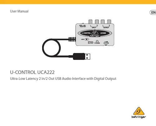
User ManualU-CONTROL UCA222Ultra-Low Latency 2 In/2 Out USB Audio Interface with Digital OutputThank youThank you for choosing the UCA222 U-CONTROL audio interface. The UCA222 is a high-performance interface that includes a USB connector, making it an ideal sound card for your laptop computer or an essential recording/playback component for studio environments that involve desktopcomputers. The UCA222 is PC and Mac-compatible, therefore no separate installation procedure is required. Thanks to its robust construction and compact dimensions, the UCA222 is also ideal for traveling. The separate headphones output allows you to play back your recordings at any time, even if you don’t happen to have any loudspeakers available. Two inputs and outputs as well as the S/PDIF output give you total connecting flexibility to mixing consoles, loudspeakers or headphones. Power is supplied to the unit via the USB interface and the LED gives you a quick check that the UCA222 is properly connected. The UCA222 is the ideal extra for every computer musician.Table of ContentsThank you ......................................................2Important Safety Instructions .....................3Legal Disclaimer ............................................4Limited Warranty ..........................................41. Before You Get Started ............................52. System Requirements ..............................63. Controls and Connectors ........................64. Software Installation ...............................75. Basic Operation ........................................76. Application Diagrams ..............................87. Audio Connections .................................108. Specifications .. (10)Terminals marked with this symbol carry electrical current of sufficientmagnitude to constitute risk of electric shock. Use only high-quality professional speaker cables with ¼" TS or twist-locking plugs pre-installed. All other installation or modification should be performed only by qualified personnel.This symbol, wherever it appears, alerts you to the presence of uninsulateddangerous voltage inside the enclosure - voltage that may be sufficient to constitute a risk of shock.This symbol, wherever it appears, alerts you to important operating andmaintenance instructions in the accompanying literature. Please read the manual.CautionTo reduce the risk of electric shock, do not remove thetop cover (or the rear section). No user serviceable parts inside. Refer servicing to qualified personnel.CautionTo reduce the risk of fire or electric shock, do not exposethis appliance to rain and moisture. The apparatus shall not be exposed to dripping or splashing liquids and no objects filled with liquids, such as vases, shall be placed on the apparatus.CautionThese service instructions are for use by qualifiedservice personnel only. To reduce the risk of electric shock do not perform any servicing other than that contained in the operation instructions. Repairs have to be performed by qualified service personnel.1. Read these instructions.2. Keep these instructions.3. Heed all warnings.4. Follow all instructions.5. Do not use this apparatus near water.6. Clean only with dry cloth.7. Do not block any ventilation openings. Install in accordance with the manufacturer’s instructions.8. Do not install near any heat sources such as radiators, heat registers, stoves, or other apparatus (including amplifiers) that produce heat.9. Do not defeat the safety purpose of the polarized or grounding-type plug. A polarized plug has two blades with one wider than the other. A grounding-type plug has two blades and a third grounding prong. The wide blade or the third prong are provided for your safety. If the provided plug does not fit into your outlet, consult an electrician for replacement of the obsolete outlet.10. Protect the power cord from being walked on or pinched particularly at plugs, convenience receptacles, and the point where they exit from the apparatus.11. Use only attachments/accessories specified by the manufacturer.12. Use only with the cart, stand, tripod, bracket, or table specified by the manufacturer, or soldwith the apparatus.When a cart is used, use caution whenmoving the cart/apparatus combination toavoid injury from tip-over.13. Unplug this apparatus duringlightning storms or when unused for longperiods of time.14. Refer all servicing to qualified servicepersonnel. Servicing is required whenthe apparatus has been damaged in anyway, such as power supply cord or plugis damaged, liquid has been spilled orobjects have fallen into the apparatus,the apparatus has been exposed to rain ormoisture, does not operate normally, or hasbeen dropped.15. The apparatus shall be connected toa MAINS socket outlet with a protectiveearthing connection.16. Where the MAINS plug or anappliance coupler is used as thedisconnect device, the disconnect deviceshall remain readily operable.17. Correct disposal ofthis product: This symbolindicates that this productmust not be disposed ofwith household waste,according to the WEEEDirective (2012/19/EU) and your nationallaw. This product should be taken to acollection center licensed for the recyclingof waste electrical and electronicequipment (EEE). The mishandling of thistype of waste could have a possiblenegative impact on the environment andhuman health due to potentiallyhazardous substances that are generallyassociated with EEE. At the same time,your cooperation in the correct disposal ofthis product will contribute to theefficient use of natural resources.For more information about where youcan take your waste equipment forrecycling, please contact your local cityoffice, or your household wastecollection service.18. Do not install in a confined space,such as a book case or similar unit.19. Do not place naked flame sources,such as lighted candles, on the apparatus.20. Please keep the environmentalaspects of battery disposal in mind.Batteries must be disposed-of at a batterycollection point.21. Use this apparatus in tropical and/ormoderate climates.MUSIC Tribe accepts no liability forany loss which may be suffered byany person who relies either whollyor in part upon any description,photograph, or statement containedherein. Technical specifications,appearances and other informationare subject to change without notice.All trademarks are the property oftheir respective owners. MIDAS,KLARK TEKNIK, LAB GRUPPEN, LAKE,TANNOY, TURBOSOUND, TC ELECTRONIC,TC HELICON, BEHRINGER, BUGERA andCOOLAUDIO are trademarks or registeredtrademarks of MUSIC Tribe Global BrandsLtd. © MUSIC Tribe Global Brands Ltd.2018 All rights reserved.For the applicable warranty terms andconditions and additional informationregarding MUSIC Tribe’s LimitedWarranty, please see complete detailsonline at musictri.be/warranty.LEGAL DISCLAIMERLIMITED WARRANTY1. Before You Get Started1.1 Shipment◊ Your UCA222 was carefully packed at the assemblyplant to assure secure transport. Should the condition of the cardboard box suggest that damage may have taken place, please inspect the unit immediately and look for physical indications of damage.◊ Damaged equipment should NEVER be sent directlyto us. Please inform the dealer from whom you acquired the unit immediately as well as the transportation company from which you tookdelivery. Otherwise, all claims for replacement/repair may be rendered invalid.◊ Please always use the original packaging to avoiddamage due to storage or shipping.◊ Never let unsupervised children play with theequipment or with its packaging.◊ Please dispose of all packaging materials in anenvironmentally friendly fashion.1.2 Initial operationPlease make sure the unit is provided with sufficientventilation, and never place the UCA222 on top of an amplifier or in the vicinity of a heater to avoid the risk of overheating.The current supply is made via the USB connecting cable, so that there is no external power supply unit required. Please adhere to all required safety precautions.1.3 Online registrationPlease register your new BEHRINGER equipment right after your purchase by visiting and read the terms and conditions of our warranty carefully.Should your BEHRINGER product malfunction, it is our intention to have it repaired as quickly as possible. To arrange for warranty service, please contact the BEHRINGER retailer from whom the equipment was purchased. Should your BEHRINGER dealer not be located in your vicinity, you may directly contact one of our subsidiaries. Corresponding contact information is included in the original equipment packaging (Global Contact Information/European Contact Information). Should your country not be listed, please contact the distributor nearest you. A list of distributors can be found in the support area of our website ().Registering your purchase and equipment with us helps usprocess your repair claims more quickly and efficiently.Thank you for your cooperation!2. System RequirementsThe UCA222 is PC and Mac-compatible. Therefore, no installationprocedure or drivers are required for the correct functioning ofthe UCA222.To work with the UCA222, your computer must fulfill thefollowing minimum requirements:2.1 Hardware connectionUse the USB connecting cable to connect the unit to yourcomputer. The USB connection also supplies the UCA222 withcurrent. You can connect a variety of devices and equipment tothe inputs and outputs.3. Controls and Connectors(1) POWER LED – Indicates the status of the USBpower supply.(2) OPTICAL OUTPUT – The Toslink jack carries an S/PDIFsignal which can be connected via a fiber optic cable.(3) PHONES – Connect a standard pair of headphonesequipped with a 1/8" mini plug.(4) VOLUME – Adjusts the volume level of the headphonesoutput. Turn the control fully to the left before youconnect the headphones to avoid hearing damage causedby high volume settings. Turn the control to the right toincrease the volume.(5) OUTPUT – Connect to a speaker system using stereo RCAcables to monitor the audio output from the computer.(6) INPUT – Connect desired recording signal using audiocables with RCA connectors.(7) OFF/ON MONITOR – With the MONITOR switch OFF,the headphone output receives the signal from the computer over the USB port (same as the RCA output jacks). With the MONITOR switch ON, the headphones receive the signal connected to the RCA INPUT jacks.(8) USB CABLE – Sends information to and from your computerand the UCA222. It also provides power to the device.4. Software Installation• This device requires no special setup or drivers, just plug it into a free USB port on a PC or Mac.•The UCA222 comes with a free version of Audacity editing software. This will help make the transfer process quick and simple. Simply insert the CD into your CD-ROM drive and install the software. The CD also contains VST plug-ins, ASIO drivers and various freeware.◊ Note – When the UCA222 is bundled with otherBEHRINGER products, the included software may vary. In the instance that the ASIO drivers are not included, you may download these from our website at .5. Basic OperationThe UCA222 provides an easy interface between yourcomputer, mixer and monitoring system. Follow these steps for basic operation:1) Connect the UCA222 to the computer by plugging theUSB cable into a free USB port. The power LED will light automatically.2) Connect the audio source that is to be recorded, such as amixer, preamp, etc. to the INPUT stereo RCA jacks.3) Plug a pair of headphones into the 1/8" PHONES jack andadjust the volume with the adjacent control. You may also monitor the output by plugging a pair of powered speakers into the OUTPUT stereo RCA jacks.4) You may also send the stereo signal in digital audio format(S/PDIF) to an external recording device via the OPTICAL OUTPUT using a Toslink fiber optic cable.6. Application DiagramsUsing a mixer to record in astudio environment:The most common application for the UCA222 is doing studio recording with a mixer. This will allow you to record several sources at once, listen to the playback, and record more tracks in sync with the original take(s).• Connect the mixer’s TAPE OUT to the INPUT RCA jacks on the UCA222. This will allow you to capture the overall mix.• Plug the USB cable into a free USB port on your computer.The POWER LED will light up.• Connect a pair of powered monitor speakers to the UCA222 OUTPUT RCA jacks. Depending on what type ofinputs your speakers accept, you may need an adapter.• You may also monitor the input signal with a pair of headphones instead of or in addition to the monitorspeakers. Turn the OFF/ON MONITOR switch to the ‘ON’position. Plug a pair of headphones into the PHONES jack and adjust the volume with the adjacent control. This will be preferable if the mixer and computer are in the sameroom as the instruments being recorded.• Take some time to adjust each channel level and EQ to ensure a good balance between the instruments/sources.Once the mix has been recorded you will be unable tomake adjustments to just one channel.• Set the recording program to record input from the UCA222.• Press record and let the music rip!Recording with a preamp such as the V-AMP 3:Preamps such as the V-AMP 3 provide a great way to record a wide selection of high-quality guitar sounds without the hassle of placing a mic in front of a conventional amp. They also allow you to record late at night without tempting your roommates or neighbors to strangle you with your own guitar cable.• Plug a guitar into the instrument input of the V-AMP 3 using a standard ¼" instrument cable.•Connect the stereo ¼" outputs on the V-AMP 3 to the stereo RCA inputs on the UCA222. This will likely require adaptors. You may also use the stereo RCA to ¼" TRS cable that is included in the V-AMP 3/UCA222 package bundle to connect from the V-AMP 3 headphone output to the UCA222 RCA inputs.• Plug the USB cable into a free USB port on your computer. The POWER LED will light up.• Adjust the output signal level on the V-AMP 3.• Set the recording program to record input from the UCA222.•Press record and wail!7. Audio ConnectionsAlthough there are various ways to integrate the UCA222 into your studio or live set-up, the audio connections to be made will basically be the same in all cases:7.1 WiringPlease use standard RCA cables to connect the UCA222to other equipment:You can also use a ¼" adapter cable:8. SpecificationsConnectors RCA, unbalancedInput impedance approx. 27 kΩMax. input level 2 dBVConnectors RCA, unbalancedOutput impedance approx. 400 ΩMax. output level 2 dBVDigital OutputSocket Toslink, optical cableOutput format S/PDIFPhones OutSocket 1/8" TRS stereo jackOutput impedance approx. 50 ΩMax. output pegel -2 dBu, 2 x 3.7 mW @ 100 ΩConnectors type AConverter 16-bit converter Sample rate 32.0 kHz, 44.1 kHz, 48.0 kHz Frequency response 10 Hz to 20 kHz, ±1 dB @44.1 kHz sample rate10 Hz to 22 kHz, ±1 dB @48.0 kHz sample rate THD 0.05% typ. @ -10 dBV, 1kHz Crosstalk -77 dB @ 0 dBV, 1 kHz Signal-to-noise ratio A/D 89 dB typ. @ 1 kHz,A-weightedD/A 96 dB typ. @ 1 kHz,A-weightedUSB connection 5 V , 100 mA max.Dimensions (H x W x D) approx. 0.87 x 2.36 x 3.46"approx. 22 x 60 x 88 mm Weight approx. 0.10 kgBEHRINGER always takes great care to ensure the highest standard of quality.Any modifications which may be necessary will be made without prior notification. Technical data and appearance of the equipment can therefore differ from the details or illustrations shown.FEDERAL COMMUNICATIONSCOMMISSION COMPLIANCEINFORMATIONResponsible Party Name: MUSIC Tribe Commercial NV Inc.Address: 5270 Procyon StreetLas Vegas, NV 89118USAPhone No.: +1 702 800 8290U-CONTROL UCA222complies with the FCC rules as mentioned in the following paragraph:This equipment has been tested and found to comply with the limitsfor a Class B digital device, pursuant to part 15 of the FCC Rules.These limits are designed to provide reasonable protection againstharmful interference in a residential installation. This equipmentgenerates, uses and can radiate radio frequency energy and, if notinstalled and used in accordance with the instructions, may causeharmful interference to radio communications. However, there is noguarantee that interference will not occur in a particular installation.If this equipment does cause harmful interference to radio or televisionreception, which can be determined by turning the equipment off andon, the user is encouraged to try to correct the interference by one ormore of the following measures:• Reorient or relocate the receiving antenna.• Increase the separation between the equipment and receiver.• Connect the equipment into an outlet on a circuit different fromthat to which the receiver is connected.• Consult the dealer or an experienced radio/TV technician for help.This device complies with Part 15 of the FCC rules. Operation is subjectto the following two conditions:(1) this device may not cause harmful interference, and(2) this device must accept any interference received,including interference that may cause undesired operation.Important information:Changes or modifications to the equipment not expressly approved byMUSIC Tribe can void the user’s authority to use the equipment.We Hear You。
本文部分内容来自网络整理,本司不为其真实性负责,如有异议或侵权请及时联系,本司将立即删除!== 本文为word格式,下载后可方便编辑和修改! ==222收信机篇一:二手短波电台的选购知识二手短波电台的选购知识短波, 电台, 知识, 选购(一)二手短波设备:如果您是个经济不太宽裕的刚入门的收听者,我建议你买如下的设备,这些都是国产退役专业接收机。
(1)退役专业接收机:是目前最容易搞到的。
a,晶体管接收机:139A/B::频率范围1。
5-18MHz,三个波段,三连调谐,体积不大。
139B是139A的发展型,用了许多的硅管,效果比139A要好,有2个陶瓷滤波器/其中一个是窄带的,灵敏度也很好,噪声也很低。
建议把它的原配耳机换掉,用另一种带软胶皮耳罩且里面是黄色震动膜盖的军用耳机代换,音量音质都有很大的提高。
它的阻抗是600欧姆,内部结构类似于老式的舌簧喇叭,不可用一般的32欧姆的立体声耳机代用,否则易损坏机器。
这种耳机还可以代换其他的国产军用接收机的原配耳机,效果也不错,但不包括XSD-12(56)的,它的耳机阻抗是2200欧姆。
139A/139B它们的价位一般在100元以下。
239/339:频率范围:1。
5-30MHz,六个波段,239主要是用锗管设计的。
三连调谐,二次变频。
339是239的发展型,噪声更低,也是二次变频,但是四连调谐,有多个陶瓷滤波器,主要用硅管设计的。
239的价位和339差不多,但性能比339差一些。
它们的价位一般在200-350元;77,77-A,70/70-2/,70-3:几种外观,电路类似,性能十分优秀的机器。
频率范围1。
5-31。
5MHz,15个波段,它们曾经是我国在70年代初生产的(来自:WWw. : 222收信机 )最好的晶体管接收机,是短波一级收信机。
七连(77和77-A)或八连(70系列)调谐,高放调谐回路十分考究,比目前几乎所有的包括数万元的高档进口机还要讲究。
数字卫星接收机说明书本说明书适用于V1.2版本的OVT/DVB-TSS-2000数字卫星接收机。
一、概述OVT/DVB-TSS-2000数字卫星接收机是一款专业的数字卫星接收机,应用于数字卫星信号的接收和转发,且带有DVB标准ASI接口输出TS流,可广泛应用于各种模拟或数字CATV 前端系统中。
二、功能特点●完全符合DVB和MPEG—2标准●支持专业的视频/音频输出接口,且带有标准ASI串行的TS流输出接口●支持DiSEqc1。
2多语言功能●支持多种可编程的卫星和转发器信息●频道记忆●前面板按键和红外线遥控用户界面●操作菜单可锁定保护●多种编辑功能(包括电视或无线电广播,组,频道名称,PID参数,卫星名称和类型)●提供屏幕频道信息的电子节目指南●多个卫星的频道记忆功能●256色的图形用户界面三、基本原理OVT/DVB-TSS—2000数字卫星接收机基本原理如下面框图所示:其大致工作原理为:卫星接收机将接收的卫星信号接行解调,然后由解码单元进行解码,再经过一些接口电路得到可以播放的模拟视频/音频信号,同时将解调后的信号经过数字逻辑处理单元进行处理打包,再进行专业的数字接口转换电路,得到ASI接口的TS流输出。
四、产品说明1。
1前面板1。
电源按键打开或关闭接收机。
2。
显示(4位7段数码管)4个数码管显示频道信息。
在休眠模式,显示当地时间。
3。
遥控传感器检测遥控器发出的红外信号。
4.CH-/CH+按键在不进入菜单模式时,用于改变频道。
1.2后面板1。
TS流输出(ASI OUT)DVB标准ASI接口TS流输出2。
高频头输入(LNB IN 13/18V 最大500mA)卫星信号输入口,用同轴电缆连接高频头(LNB).3.高频头输出(LNB OUT)卫星信号环出口,可连接其它的卫星信号接收设备。
4.音频输出音频插座提供立体声输出。
5.视频输出视频插座提供一个复合的视频输出。
6.没有使用对于本版本接收机,此接口没有使用。
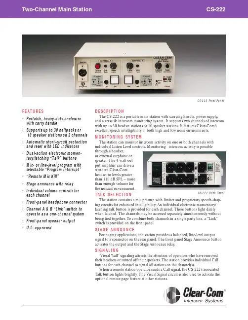
DESCRIPTIONThe CS-222 is a portable main station with carrying handle, power supply,and a versatile intercom monitoring system. It supports two channels of intercom with up to 30 headset stations or 10 speaker stations. It features Clear-Com’s excellent speech intelligibility in both high and low noise environments.MONITORING SYSTEMThe station can monitor intercom activity on one or both channels withindividual Listen Level controls. Monitoring intercom activity is possiblethrough a headset, or external earphone or speaker. The 4-watt out-put amplifier can drive a standard Clear-Com headset to levels greater than 110 dB SPL – more than enough volume for the noisiest environment.TALK SELECTIONThe station contains a mic preamp with limiter and proprietary speech-shap-ing circuits for enhanced intelligibility. An individual electronic momentary/latching talk button is provided for each channel. These buttons light dimly when latched. The channels may be accessed separately simultaneously without being tied together. T o combine both channels in a single party line, a “Link”switch is provided on the front panel.STAGE ANNOUNCEFor paging applications, the station provides a balanced, line-level output signal to a connector on the rear panel. The front panel Stage Announce button activates the output and the Stage Announce relay.SIGNALINGVisual “call” signaling attracts the attention of operators who have removed their headsets or turned off their speakers. The station provides individual Call buttons for each channel to signal all stations on the channel(s).When a remote station operator sends a Call signal, the CS-222’s associated Talk button lights brightly. The Visual Signal circuit is also used to activate the optional remote page feature at other stations.FEATURES•Portable, heavy-duty enclosure with carry handle •Supports up to 30 beltpacks or 10 speaker stations on 2 channels •Automatic short-circuit protection and reset with LED indicators •Dual-action electronic momen-tary/latching “Talk” buttons •Mic- or line-level program with selectable “Program Interrupt” •“Remote Mic Kill” •Stage announce with relay •Individual volume controls for each channel •Front-panel headphone connector •Channel A & B “Link” switch to operate as a one-channel system •Front-panel speaker output •U.L. approvedCS-222 Back PanelCS-222 Front PanelSPECIFICATIONSMICROPHONE PRE-AMP (Dynamic Headset Input)Impedance: 1 k ΩLevel: -55 dBv *nominal, -10 dBv max.Frequency Response: 250 Hz - 12 kHz,contoured for intelligibility Limiter Range: 20 dBGain from Headset to Intercom Line: +41 dB HEADPHONE AMPLIFIER Load Impedance: 50 - 2,000 ΩOutput Level: > +20 dBv across 600 ΩDistortion: < 0.2% THD @ 1 kHzFrequency Response: 200 Hz - 18 kHz, +- 2 dB INTERCOM LINE DRIVE/RECEIVE CIRCUITSImpedance, Output Load: > 10 k Ω, 200 Hz - 10 kHz Level,Line: 200 Ωload Nominal: -9 dBvMaximum: +5 dBv before clip Sidetone Null Capability: >25 dB, 200 Hz - 10 kHzCrosstalk, Station-Induced Channel-to Channel:>60 dBNoise, S/N Ratio in Listen Channels: >60 dB SYSTEM SPECIFICATIONSIntercom Line Length: 5,000 ft. maximum Intercom Line Length for Crosstalk <-52 dB:500 ft. maximumMaximum No. of Stations Per Intercom Line: 100Frequency Response: 150 Hz - 18 kHz, +- 2 dB POWER SUPPLYOutput Power: +30 volts DC, +- 1 V Output Current: 1 Amp Reset Current: 1 AmpHum & Noise: < -1 mV AC RMSStation Capacity: 30 headset stations or 10 speaker stationsREAR-PANEL CONNECTORS Intercom: (6) XLR-3M (3 per channel)Program: (1) XLR-3FStage Announce: (1) XLR-3MAnnounce Out: SPST terminal block REAR-PANEL SWITCHES Power On/Off: 1Termination On/Off: 2Mic/Line Select For Program Input: 1AC POWER REQUIREMENTS105 - 125/210 - 250 Volts, 50 - 60 Hz, 60 VA DIMENSIONS3" H x 8.125" W x 10" D (76 x 206 x 254 mm)WEIGHT 5.2 lbs (2.3 kg)All specifications are subject to change without notice.*0 dBv is referenced to 0.775 volts RMSClear-Com Intercom Systems: 945 Camelia Street, Berkeley, CA 94710(510) 527-6666, Fax (510) 527-6699, International Sales: PO Box 302, Walnut Creek, CA 94597, (510) 932-8134, Fax (510) 932-2171© 1997 Clear-Com Intercom Systems. PL-Pro is a Registered Trademark of Clear-Com. #CS222/797REMOTE MIC KILL (RMK)Pressing the RMK button will turn off the microphone talk circuits of all Clear-Com beltpacks eliminating annoying noise from the open headset microphones.SIDETONESidetone control allows the operator to vary the level of his or her own voice as heard in the headset. The CS-222 provides individual sidetone adjustment for each channel.PROGRAM INPUTThe station accepts a balanced, mic- or line-level program signal for monitoring in the headset and/or mixing the intercom audio on either or both channels. The front panel provides a local Program Monitor volume control and individual Program Send level controls. It also provides a Program Send on/off/interrupt switch for each channel. When interrupt is selected, program is interrupted when the Talk button is pressed.POWER SUPPLY AND SUPPLY SYSTEM PROTECTIONThe CS-222 provides visual indication of power supply conditions. In the event of a DC short circuit or current overload, the station’s electronic overload protection circuit will shut down the DC output to avoid damage. As soon as the fault condi-tion is removed, the auto-reset circuitry will automatically restore system power –even under full load conditions. There is no need to disconnect stations to allow the power supply to reset.T o increase system capacity, one or more power supplies can be connected in parallel with the CS-222. In such configurations, the main station’s “intelligent”power-sensing capability lets the system automatically reset all power supplies after a DC short or AC power loss in the system, no matter how large the system is.SIMPLE SET-UPThe CS-222 connects to remote stations with standard, two-conductor shielded mic cable. With the optional rackmount kit, the main station can mount in a standard 19" equipment rack, requiring only two rack spaces. The CS-222 con-forms to the highest standards of reliability and performance, providing trouble-free service over a wide-range of environmental conditions.CS-222 BLOCK DIAGRAM。
RH-222产品说明书v1.1物品清单小心打开包装盒,检查包装盒里面应有以下配件:主机(1)天线(1)充电器(1)车充(1)对讲耳机(1)合格证(1)保修卡(1)注:括号中数字表示设备数量如果发现有所损坏或者任何配件短缺的情况,请及时和经销商联系。
目录第一章用户手册简介 (2)第二章产品概述 (2)2.1产品简介 (2)2.2 产品型号说明 (2)2.3主要功能及特点 (2)2.3.1基本功能 (3)2.3.2 压缩处理功能 (3)2.4 主要应用 (3)第三章硬件安装 (3)2.1注意事项 (3)3.2 面板说明 (4)3.2.1 主机前面板 (4)3.2.2 主机底面板 (4)3.2.3 主机上面板 (5)3.2.4 指示灯 (5)3.3.2 充电 (5)附录 1 (6)附录 2 (8)附录 3 (8)第一章用户手册简介感谢您购买RH-222系列视频服务器!在您准备使用本产品之前,请先仔细阅读本手册,以便能更好的使用本产品的所有功能。
本手册的用途是帮助您熟悉和正确的使用RH-222系列视频服务器第二章产品概述2.1产品简介目前,公检法、抢修、环保、保险定损、水利、电力、铁路、公路等行业对移动监控都有各自需求,传统监控设备无法满足相应需求。
数码相机、DV等设备虽然能在一定程度上实现移动记录、现场取证的工作,却无法实现数据的实时上传。
随着3G技术的发展与应用,无线网络的带宽得到了大幅提升,高质量的视频图像传输变为了可能。
在这种背景下,本公司基于多年的安防行业沉淀,结合3G技术,推出便携式单兵监控系统。
该系统还可以与中研瑞华自主研发的“3GGPS”监控平台实现对接,为用户提供更加丰富的特色功能。
2.2 产品型号说明2.3主要功能及特点1路视频,音频输入,视频分辨率最高支持D1(704*576)分辨率编码,支持GPS定位,支持3G无线传输,支持SD卡存储。
2.3.1基本功能视频压缩技术:采用H.264视频压缩技术及OggVorbis音频压缩技术,压缩比高,且处理非常灵活。
U-CONTROL UCA222Ultra-Low Latency 2 In/2 Out USB Audio Interface with Digital Output使用说明书V 7.0序言感谢您选择了 UCA222 U-CONTROL! 它是一款高性能接口, 设有可与电脑笔记本或录音棚 (需使用台式电脑)中必须的录音设备相连接的 USB 接口。
UCA222 可与PC 及 MAC 电脑相兼容, 且无需独立的安装。
由于结构坚固, 便于携带的特点, 所以非常适合旅行时携带。
独立的耳机输出端令您随时收听录制的音乐, 即使没有喇叭也没关系。
另外, 它设有 2 个输入及 2 个输出端及 S/PDIF 输出端, 这为您连接调音台, 喇叭和耳机提供了极大的便利。
UCA222 可用 USB 供电, LED 指示灯可快速检查是否连接好。
它是每位电脑音乐人不可缺少的工具。
目录序言 (2)1...启动之前. (4)2...系统要求 (5)3...控制与接口 (5)4...软件安装 (6)5...基本操作 (6)6...应用图 (7)7...音频连接 (9)8...技术参数 (9)(CN).安全须知1. 请阅读这些说明。
2. 请妥善保存这些说明。
3. 请注意所有的警示。
4. 请遵守所有的说明。
5. 请勿在靠近水的地方使用本产品。
6. 请用干布清洁本产品。
7. 请勿堵塞通风孔, 安装本产品时请遵照厂家的说明, 通风孔不要覆盖诸如报纸、桌布和窗帘等物品而妨碍通风。
8. 请勿将本产品安装在热源附近, 如暖气片, 炉子或其它产生热量的设备 (包括功放器)。
产品上不要放置裸露的火焰源, 如点燃的蜡烛。
9. 请只使用厂家指定的附属设备10. 请只使用厂家指定的或随货销售的手推车, 架子,三 角架, 支架和桌子。
若使用手推车来搬运设备, 请注意安全放置设备, 以 避免手推车和设备倾倒而受伤。
11. 如果液体流入或异物落入设备内,设备遭雨淋或受潮, 设备不能正常运作或被摔坏等, 设备受损需进行维修时, 所有维修均须由合格的维修人员进行维修。
中、短波广播接收天线的配置和使用作者:董涛来源:《大陆桥视野·下》2013年第01期摘要天线是一种高频电能与电磁波能的转换器,是无线电通信系统重要的前端器件,其本身的质量直接影响着无线电系统的整体性能。
本文阐述了中、短波广播接收天线的使用与监测工作的内在联系,对原有监测台和新建监测台各种天线的技术特点进行了比较,阐述了天线的使用方法和注意事项。
关键词天线广播监测电气特性天线使用一、前言监测台使用接收天线的目的,是通过接收天线的技术特性的运用达到预期的效果,使接收信号最强,降低干扰,从而提高信噪比。
因此,天线性能的好坏,直接关系到监测工作完成的质量,同时,科学、合理的使用天线,对更好地完成监测工作、提高监测工作的效率同样具有重要的作用。
二、监测任务与天线选择接收中、短波段广播电台的信号是监测台的基本任务之一,按要求分别进行如下工作:广播效果的评估;播出质量的监听;发射特性的测量;境外电台广播动态的监测;频谱监测。
根据各项监测任务的不同要求,监测台需配置不同形式的接收天线。
进行播出质量的监听和发射特性的测量,要求有足够强的接收信号,便于判别播出异态和避开同频道上其他发射机的干扰,以便准确测量发射机的发射特性(调幅度、频偏容限度)。
进行境外电台广播动态的监测,也同样需要足够强的接收信号,对电台的归属进行辨别,特别是对一些弱信号电台,尽可能通过高性能天线,提高信号强度,对确保准确、及时地发现频率的变化具有重要作用。
进行上述项目的监测,要求接收天线具有方向性强、增益系数高的特点。
评估广播效果则需要用全向天线接收信号。
因为,广播宣传的服务对象是广大的普通听众,而普通听众使用的是民用接收机,若使用监测台强定向、高增益的天线接受的电台信号,不能准确反映收测地区实际的广播效果。
因此,应用最接近民用接收机收听效果的全向天线来评估广播的实际效果。
频谱监测主要是掌握监测台所在地区上空的中短波波段的频谱负荷情况,需要同时比较来自不同方向的电台信号在接收地区的强弱程度,要用全向天线来客观评定各频道的负荷程度。
YEASU SYSTEM 600收发信机简易使用说明书Ⅰ特性说明书Ⅰ-1概要1.接收机频率范围:50kHz——29.99999MHz2.发射机频率范围:1.8——29.99999MHz(仅限于被选择的记忆频道或者ITU海事频道;业余无线电频道)3.发射模式: J3E(USB,LSB) 用于语音的接收与发射。
A1A(CW) 用于莫尔斯电报通信A3E(AM)H3E(2182模式,仅限于海事机)J2B(USB,LSB), 用于ASFK模式下数据接收与发射。
4.频率合成器步进:10Hz 100Hz 1kHz5.频率稳定度:±10ppmz在0℃~+40℃ (仅限于标准版)±2ppmz在0℃~+50℃ (仅限于加装W/TCXO-4晶体)6.适合工作的温度范围:-10℃~+50℃7.天线阻抗:50Ω(最大的允许驻波比为2:1)8.供电电压:13.5V DC±10% 负极接地9.功率消耗:1.2A(接收或者没有信号时)20A(发射输出100W时)10.机器尺寸(WHD):244×104×286mm11.机器重量:4.5kgⅠ-2发射机1.功率输出:100W(仅限于J2B、J3E、A1A模式)25W(仅限于A3E、H3E)2.调制类型:单边带SSB:滤出载波,平衡调制调幅AM: 低电平(早期版本)3.杂散辐射:在峰值功率输出下为40dB4.单边带载波抑制:在峰值功率输出下大于40dB5.不需要的边带抑制:在输入1.5kHz的调制信号,并且在峰值功率下至少50dB。
6.单边带模式下的音频响应:对于400Hz——2600Hz的音频响应不小于-6dB7.占用带宽情况:A1A:<0.5kHzJ2B:< 3.0kHzJ3E:< 3.0kHzH3E:< 3.0kHzA3E:<6.0kHz8.第三阶单边带互调失真:在14MHz,100瓦的峰值功率下优于-25dB9.麦克风特性阻抗:500——600ΩⅠ-3接收机1.电路类型:双变频超外差2.中频频率:第一中频:47.055MHz第二中频:8.215MHz3.灵敏度:(相对于10dB的信噪比):0.5——1.8MHz: J2B/J3E/A1A模式下灵敏度为2μVA3E模式下灵敏度为8μV1.8——29.999MHz: J2B/J3E/A1A模式下灵敏度为0。
轻松学业余电台通信系列文章(4)业余电台设备基本操作与调整荣新华在上一期文章中,我们为初学短波通信的爱好者简要介绍了短波业余电台开台前的准备工作,包括操作证书考核、电台室基本布置和天线的架设施工与基本调试。
在本篇文章中,我们从一般的角度介绍收发信机、天线调谐器和功率/驻波比表等常见设备的基本操作与调整。
需要提请大家注意的是,对任何设备的操作与调整最好严格遵照说明书进行,否则操作的失误有可能会造成设备损坏。
如果手头没有说明书,大家可以参考本文中介绍的一般性原则。
由于设备种类多样,我们介绍的原则只能是针对一部分设备完全适用,对其它设备仅供参考。
收发信机操作收发信机(transceiver)俗称为电台,顾名思义,是将接收机和发射机合一的设备。
与普通的移动电话不同,用作业余电台的收发信机一般不能接收和发射同时工作,在缺省情况下,收发信机处于接收状态,可通过手按PTT键或用声控(VOX)的方式切换到发射状态。
收发信机的一般操作步骤如下:1. 开机前仔细检查设备连线是否正确,特别要检查天线有无妥善连接。
检查各旋钮的控制功能,应使其均处于适中位置。
2. 打开电源开关,选择工作频率,设置工作模式(对于SSB通信,一般小于9MHz为LSB,否则为USB)。
调整增益旋钮,使接收音量合适。
把控制发射功率的旋钮调小一些。
先转动调谐旋钮在工作频率附近收听一段时间,不要急于发射。
对于一些老式收发信机来说,这段收听时间是必要的预热过程,可确保工作频率稳定。
3. 开始的时候应使用较小发射功率,发现一切正常(功率指示会根据说话或发报摆动,驻波比处于安全范围)后方可在接收状态时调大功率。
如发现不正常,要及时停止发射,要对天线系统甚至对收发信机本身进行检查。
为了避免损坏设备,我们强烈建议大家不要在发射时对收发信机作任何调节。
4. 操作完毕要把各旋钮恢复到适中位置,关闭电源,拆去天线插头,并切断交流电源。
再次强调:不要在不接天线的情况下或者天线的驻波比很差的情况下发射。
短波收音机收听手册当下市面上的全波段(WorldBand)数调短波收音机调谐的频率跨度很大,典型的调谐范围从150KHz到30000KHz,几乎囊括长波、中波、短波的全部波段。
根据国际无线电联盟的协定,无线电频率被划分并供应给不同用途的使用者。
虽然偶有犯规者,但绝大多数台(站)都恪守许可使用的频率.150KHz及以下.这个频率的无线电波不能通过电离层传播,却可以很好地穿透海洋的深处,因此,在这个频率下可以发现许多做潜艇通讯的军事电台.德国、英国、日本、瑞士和白俄罗斯等国的标准时间标准频率发播台的发射频率都在20-80khz之间,普通收音机是根本接收不到的。
150到540KHz。
这是BCLer和Dxer通称的长波段。
在收音机里能听到的大多数信号是一些信标台不断重复摩尔斯(Morse)电码呼号.长波广播从153KHz启用,大功率的长波广播以俄罗斯和东欧国家为甚,非洲及澳大利亚、蒙古和前苏联加盟共和国等部分亚太地区国家也有长波广播,但我国广播并未染指这一领地。
法国标准时间标准频率发播台使用162khz.在长波的高端,可以接收到一些RTTY(无线电传)信号。
海洋气象和安全广播,如无线电爱好者熟知的VTEX(航行警告自动通信系统)就是在512KHz发射。
这个波段的最好接收时间是秋冬季的夜晚。
我国的北方地区容易接收到独联体国家的长波广播。
540KHz到1710KHz。
这是中波广播.亚洲和中南美洲地区的中波起始段被划为530KHz。
传统收音机的中波到1600KHz结束,而实际意义上的中波广播波段却在1710KHz结束。
从1610到1710KHz是新的中波扩展领域,从1997年开始,不断有电台在这一波段上播音,给无线电爱好者提供了精彩的DX(远程无线电接收活动)契机。
但1700khz以上频率入驻的中波广播电台寥寥无几,据WRTH(《世界广播电视手册》)最新记录,全球仅有两家广播电台在1700khz—-1710khz发声,澳大利亚转播当地赛马和服务偏远地区土著民的广播电台就使用1701KHz,阿根廷RadioPalacio—AM1710电台使用1710KHz,发射功率均在1KW以下,远程接收极具挑战性。