Noiselike pulses with a broadband spectrum generated from an erbium-doped fiber laser
- 格式:pdf
- 大小:227.28 KB
- 文档页数:3

屏蔽杂音窥见真我作文英文回答:The prompt for this essay asks me to discuss the concept of blocking out noise to discover one's true self. This is an interesting topic because in today's fast-paced and noisy world, it can be challenging to find moments of peace and clarity. However, by intentionally creating a space free from distractions, it is possible to gain a deeper understanding of oneself.To begin with, one effective way to block out noise is through meditation. By sitting in a quiet room and focusing on one's breath, it becomes easier to let go of external distractions and connect with one's inner self. Meditation allows us to observe our thoughts and emotions without judgment, providing valuable insights into our true nature.Another method to shield ourselves from noise is by spending time in nature. Nature has a calming effect on themind and body, allowing us to escape the hustle and bustleof daily life. Whether it's taking a walk in the park,hiking in the mountains, or simply sitting by the beach, being in nature helps us reconnect with our authentic selves.Furthermore, it is essential to limit exposure to negative influences, such as social media and toxic relationships. These external factors can cloud ourjudgment and prevent us from truly understanding who we are. By being mindful of the content we consume and the peoplewe surround ourselves with, we can create a more positive and nurturing environment for self-discovery.In addition to these practical steps, it is crucial to cultivate self-awareness. This involves paying attention to our thoughts, emotions, and behaviors. By regularlyreflecting on our actions and motivations, we can gain a deeper understanding of our true selves. Journaling, therapy, and self-reflection exercises can all be helpful tools in this process.中文回答:这篇文章的要求是讨论屏蔽杂音以发现真正的自我。

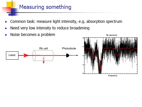
Noise Before we study the RF circuit, we will introduce some important parameters. One of them is noise.The radio channel is free space. Random processes are an integral part of communications.If an ideal signal is binary signal shown in this figure , which is corrupted by noise, the final signal can be represented like in that figure.Noise can be defined as the random fluctuation of electrical power that interferes with the desired signal and inhibit communication.. It is usually random and varied. It cannot be avoided completely, but its effects can be reduced by various means, such as reducing the signal bandwidth, increasing the transmitter power, and using low noise amplifiers for weak signals.Noise in communication systems originates both in the channel and in the communication equipment. There are many possible sources of noise. It is helpful to divide noise into two types: external noise which is a property of the channel and internal noise which originated within the communication equipment.In this class, we will focus on the internal noise.Both passive components (resistor) and active devices (diode, transistor, tube ) can be the noise source. These noises are produced by the random motion of eletrons. These noises can be expressed by fluctuation noise.Noises arising in electron tubes, semiconductor diodes, bipolar transistors, or field effect transistors come from a variety of mechanisms.For diodes, a random emission of electrons and holes produces noise,In a bipolar transistor, there is in addition partition noise. This represents the fluctuation in the path that charge carriers take between the base and the collector after leaving the emitter. There is in addition 1/f , or flicker noise that is caused by surface recombination of base minority carrier at the base-emitter junction.Noise parameters1. Voltage average of fluctuation noisedt t v T v Tn T n )(1lim0⎰∞→-=2. Root mean square value (RMS)--∞→-=-=∆⎰2202])([1)(n T n n T nv dt v t v T Lim t vdt t v T Lim t v T n T n)(1)(022⎰∞→-=1. Resistance thermal noiseThe fluctuation noise of resistor is caused by the random motion of electrons in a conductor due to heat.It might seem that we could transmit at any level of signal power and simply introduce a suitable amount of amplification at the receiver end. Unfortunately, this is not the case due to the fact that the signal will be competing with an ever present environment of random signals or noise.(f s fSo the noise power available from a conductor is a function of its temperature:n T f kT N ∆=T N =noise power in wattsk =Boltzmann ‘s constant , 231038.1-⨯ joules/Kelvin(J/K)T =absolute temperature in kelvins (K) ;this can be found by adding 273 to the celciustemperature.n f ∆=noise power bandwidth in Hertz.Noise VoltageOften we are more interested in the noise voltage than in the power involved.R v P 2=Rv P 2=R v P 2=-2nv N R LRThe noise voltage in a circuit must depend on the resistances involved.Fig 1 shows a resistor N R that serves as a noise source connected across another resistorL R which is a load. The noise voltage is represented as a voltage source -2nv in series with anoiseless resistance N R .Assumed a matched load,one-half the noise voltage appear across the road, and the rest is across the resistor that generates the noise.R f kT R N vv n T n n ∆===4)2(22 For example, a simple resistor will create a noise voltage n v due to the random thermal motion of its electrons and this can be shown to have an rms voltage that satisfiesf kTR v n ∆=-42Where T (in Kelvin) is the absolute temperature, f ∆ (in hertz)is the bandwidth of the measurement, R(in ohms) is the resistance and k is the Boltzmann constant. Z providing R isinterpreted as the resistive part of the impedance. From a modeling viewpoint, the noise source can be regarded as an ideal voltage source of magnitude n v in series with a noise free impedance. Alternatively ,It can be regarded as an ideal current source of magnitude n i in parallel with the impedance (f kTG in∆=-42).RG 1=This equation is based on the assumption that power transfer is maximum. That is the source (the resistance generating the noise) and the load (the amplifier or other device that receives the noise0 are assumed to be matched in impedance._2n v _2nI R G RLosslessy reactance can not product thermal noise. In the resonance circuit, the noise is produced by lossy resistance.3. equivalent noise bandwidthIf the noise power density is )(f S⎰=21)(f f df f S P2)()()(f A f S f S i o =The equivalent noise bandwidth is calculated by the noise power equal. It depends on the rectangular area. The width is n f ∆, the height is )(o o f SIt is equal to the area of )(f S o that the width is n f ∆n f ∆ is equivalent bandwidthdf f A f S df f A f S v i i n222)()()()(⎰⎰∞+∞+-==)()(022f A df f A B L ⎰+∞=)(f A : power transmission function 0f : frequency in the middleFor series circuits or parallel circuits, It can be found by taking the square root of the sum of the squares root of the individual voltages or currentsMathematically, we can say, for voltage source in series+++=232221N N N Nt V V V VAnd similarly, for current sources in parallel+++=232221N N N Nt I I I I)(f S o nf ∆When a circuit contains several resistors, the total noise power can be calculated by suitable combination of the resistors . Two resistors in series each produce a mean-squared voltage. Since the individual noise voltage sources are uncorrelated ,the total mean-squared voltage is the sum of the mean-squared voltage of each of the two resistors .Similarly two conductance in parallel each produce a mean-squared noise current that may be added when the two conductances are combined, since the noise currents are uncorrelated.It should be emphasized that two noise voltage cannot be added together ,only the mean-squared values can be added.2. Antenna thermal noiseEquivalent circuit consists of radiation resistance A R and reactance A X .Radiation resistance represents the power of antenna receiving or radiation signaling.n A A n f R kT V ∆=-423. Transistor noiseThe main noises in the transistor include thermal noise , shot noise, distribution noise, flicker noise. The thermal and shot noise are white noises, the others are color noise.3.1 Thermal noiseThermal noise always exists in the base resistance 'bb r .The emitter and collector have seldom resistance.3.2 Shot noiseShot noise is due to random variations in DC current flow in active devices such as tubes, transistors, and semiconductor diodes. These variations are caused by the fact that current is a flow of carrier (electrons or holes), each of which carries a finite amount of charge. Current can thus be considered as a series of pulses, each consisting of the charge carried by one electron. The name “shot noise ” describes the random arrival of electrons arriving at the anode of a vacuum tube, like individual pellets of shot form a shotgunIn the bipolar transistor , the carrier charges that are injected into the base level can injected to the collector and emitter. It can be represented by the current fluctuation of emitter current. Shot noise is usually represented by a current source.Shot noise arise from random variations of a DC current ,0I and is especially associated with current carrying active devices. Shot noise is most apparent in a current source with zero-shunt source admittance.Then the DC current istqn I ∆=q is the charge of an electron shot noise powerf qRI N s ∆=02The corresponding shot noise current :f qI i ∆=-022It is a Gaussian white process. The noise current is given by the equation:f qI qI i o n∆==-222Whereq =magnitude of the charge on an electron, equal to 19106.1-⨯coulombI =average current0I =DC bias current in the devicef ∆= bandwidth over which the noise is observed ,in hertz Shot noise has random amplitude and flat spectrum.em bb b e b e cb c r g r r r r r r 0'0'')1(αα==-==n b bnf kTr v∆=-42n E enf qI i ∆=-223.3 partition noise (distribution noise)It occurs only in devices where a single current separated into two or more paths. An example of such a device is a dipolar junction transistor , where the emitter current is the sum of the collector and base currents. As the charge carriers divided into one stream or the other, a random element in the current is producedn C cnf qI I∆-=•-)1(2022ααaf jf /10+=•ααstate base common of t coefficien amplifier current is α3.4 flicker noise (f1) The noise power varies inversely with frequency. There is proportionately more energy at the low-frequency end of the spectrum than with white noise. It can have some influences in the low frequency. Its frequency spectrum is inversed proportion to the frequency. It is found in tubes but is a more serious problem in semiconductors and in carbon resistors. It is not fully understood, but it is believed to be caused by variations in carrier density.fWLC K V OX n 12=-K: process-dependent constantIn the base level, noise is thermal noise , In the emitter, is shot noise, in the collector is distribution noise.bc --2cn ir12Fnf4 Diode noiseFor diode, we only consider the shot noise. It has not distribution noise and thermal noise is very small.5 field effect transmitterThere are four kinds of noise 1) shot noise in the gate leveln G ngf qI i∆=-222) Channel resistance thermal noise_2ngn f ndf kTg is ∆=-42n f n f g kT V s∆=-)1(4213) Equivalent resistance noise between source and gate leveln n f kTR V∆=-4224) flicker noise (f1) The noise power varies inversely with frequency. There is proportionately more energy at the low-frequency end of the spectrum than with white noise. It can have some influences in the low frequency. Its frequency spectrum is inversed proportion to the frequency. It is found in tubes but is a more serious problem in semiconductors and in carbon resistors. It is not fully understood, but it is believed to be caused by variations in carrier density.fWLC K V OX n 12=-K: process-dependent constantInput-referred noiseThe internal noise of a noisy two port circuit can be modeled by two input noise generators: 1) a serial voltage source -2nv 2) a parallel current source -2n i 3)a noiseless circuit_2v-2nv : an equivalent output noise power to the input by shorting the input port -2ni : an equivalent output noise power to the input by leaving the input portThis is an example:_2nDiiv +-+-:22,2,2,L Dn R n on R iv vL•+=---By shorting the input , and leaving the -2niL m iLi m i o v R g v R v g v v A ===The RMS of output noise voltage --⨯=222,nvon v A v22,22,222,2,22,2)()(mD n L m R n L m LDn R n vo n ngiR g vR g RivAvv LL------+=•+==≈22,mD n gi-BY leaving the input open2222222,))(()(L m i nvi non R g Z i A Z i v---==2222,2,2)(iL m LD n R n nZ R g R ivi L•+=---2222,2)(iL m L Dn nZ R g R ii •=--For )3/2(42m nDg kT i=-)3/(82m ng kT v =- )3/(822i m nZ g kT i =-In general, the noise in an electronic circuit can be modeled by removing the noise sources from within the circuit and replacing them by equivalent current and voltage sources at the input.The main reason for studying and calculating noise power or voltage is the effect that noise has on the desired signal. It is not really the amount of noise that concerns us but rather the amount of noise compared to the level of the desired signal. It is the ratio of signal to noise powerthat is important, rather than the noise power alone.The signal-to noise ratio is one of the most important parameters of any communication system.The SNR is defined as the ratio of the signal power to the total noise power.The crucial quantity in assessing circuit performance is the signal-to-noise ratio (SNR), defined bypowernoise power signal N S SNR ==It is usually expressed in decibels:NSP P dB SNR log10)(= In a radio receiver, SNR will directly relate to the quality of the demodulated signal. The change in SNR through an RF circuit is normally measured in term of its noiseThere is another represent method about noise figurei o i o i o o i S S N N N S N S F //=••=pi oA N N F •=i o p S S A /=pi oA N N F •=p A : the power gain of the amplifierp i o A N N •=1: the output noise power that is the amplified source noise through theamplifier2o N : the noise power of this amplifier 201o o N N N +=.0121N N F o += The average noise figure⎰⎰=dff A df f A f F AV F pp )()()()( Noise figure is occasionally called noise factor. For a noiseless circuit, F=1, This is because both the input signal and the input noise are amplified/attenuated) by the same factor and noadditional noise is introduced.In reality, the finite noise of a system degrades the SNR , yielding F>1.-2-2+-f kTR vS R S∆=--42in SNR is the ratio of the input signal power to the noise generated by the sourceresistance,S R-=22SR inin VV SNR22222])([v sn n R inv out A R i v v v A SNR s----------------++=fkTR R I V VR I V VR I V V F S S n n R S n n R S n n R SSS∆++=++=++=------------------------------------------------4)(1)(1)(222222 v A is a voltage gain from P to out VThe output signal power:222ins in in L vo Z R Z V R A P +=In the output port, the external noise power caused by S R is :222'inS in R L v o Z R Z V R A N S +•=-The noise power of equivalent of input noise:------------------------------+++=22'')(inS in S n in S in n L vo Z R Z R I Z R Z V R A N 2222'''])([inS in S n n R L vooZ R Z R I V V R A N N N S+++=+=---------------])([])([2222222222------------------------------++=++++==S n n R ininS inS n n R L v ins inin L vo o R I V V V Z R Z R I V V R A Z R Z V R A N PSNR SSfkTR A v f kTR A R I V f kTR A f kTR R I V F S v outn S v Sn n s vS S n n ∆=∆++∆=∆++=-------------------------4141])(4[4)(122,2222The noise figure can be calculated by rated power and rated power gain:The rated power is the maximum power of output by source. So the input resistance i R must be matched with the internal resistance s R of the amplifiers i R R =The input rated power isThe input rated noise power isn sns s nni f kT R f kTR R V P ∆=∆==-4442'At the output port , L o R R = output matches.Rated power gain is the power gain that input and output match.ss si R V P 42'=pHn nono so ni si A f kT P P P P P F ∆=='''''// For q : dismatch coefficientq P P ⋅='''''''''//////noso ni si o no o so i ni i si no so ni si P P P P q P q P q P q P P P P P F ===Equivalent noise temperatureIt is another way of specifying the noise performance of a device. It has nothing to do with the actual operating temperature of the circuit. For a linear network, if it produce white noise, we can present this internal noise in the input port, A resistance that have e T temperature will replace the noise., and the network is noiseless. e T is an equivalent noise temperature.The rated input noise power is n e ni f kT P ∆='' ,It is amplified and the output rated noisepower pH ni no A P P '''2=The original noise power n ni f kT P ∆=' ,Its output power :''1ni pH no P A P =T T f kT A kT A P P P P P P P F e n pH e pH no no no no no no no +=∆+=+=+==111'1'2'1'2'1'1' T F T e )1(-=The total output noise is:n e pH no no no f T T A P P P ∆+=+=)('2'1'RRNoise Figure of cascaded stageWhen two or more stages are connected in cascade, as in the receiver, the noise figure of the first stage is the most important in determining the noise performance of the entire system because noise generated in the first stage is amplified in all succeeding stages. Noise produced in later stages is amplified and noise generated in the last stage is amplified least of all.It is possible to derive an equation that relates the total noise figure to the gain and noise figure of each stage.''/siso pH P P A =2o P svThe first stage has a gain 1A and noise figure 1NF , and the second-stage gain and noise figure are 2A and 2NFThe noise power input to the first stage isn i N f kT P ∆=The output power of the first stage is:111pH Ni No A P F P =The output power produced by the first stage amplifier is :11111)1(pH n pH n No n A f kT NF A f kT P P ∆-=∆-=222)1(pH n n A f kT NF P ∆-=Thus the total noise power at the output of the two-stage system is :22212)1(pH n pH No No A f kT NF A P P ∆-+==2No P 22211)1(pH n pH pH Ni A f kT NF A A P NF ∆-+=12121pH n pH No T A NF NF f kT A P NF -+=∆=Friis ’ formula can be generalized to any number of stages:+-+-+-+=3214213121111A A A NF A A NF A NF NF NF TSensitivity and selectivityThe sensitivity of a receiver is normally defined in term of the minimum detectable signal (MDS) that the system can detect with acceptable signal-to-noise ratio.min,min ,/out R in out inSNR P P SNR SNR F S ==))()((min ,min ,min ,out out R in SNR F f KT SNR F P P S ∆=••=)(log 10)()/(|min ,min ,dB SNR f dB F Hz dBm kT dBm P out in +∆++=K T 290=Dynamic rangeDR is generally defined as the ratio of the maximum input level that the circuit can tolerate to the minimum input level at which the circuit provides a reasonable signal quality.)(log 10)()/(174|min ,min ,dB SNR f dB F Hz dBm dBm P out in +∆++-=。

对降噪的看法英语作文Title: Perspectives on Noise Reduction。
In today's fast-paced world, noise pollution has become an inevitable part of our daily lives. From bustling city streets to the constant hum of electronic devices, we are constantly bombarded with various forms of noise. In response, the concept of noise reduction has gained significant attention as a potential solution to alleviate the negative impacts of excessive noise. In this essay, we will explore different perspectives on noise reduction and its implications.Firstly, proponents of noise reduction argue that reducing noise levels can significantly improve overall well-being and quality of life. Excessive noise has been linked to various health issues, including stress, anxiety, and even cardiovascular problems. By implementing measures to reduce noise pollution, such as soundproofing buildings, creating green spaces, and enforcing noise regulations,communities can create more peaceful environments conducive to mental and physical health.Moreover, noise reduction can have positive effects on productivity and concentration. In environments where noise levels are high, such as open-plan offices or busy classrooms, individuals may struggle to focus on tasks and maintain productivity. By reducing noise distractions through measures like acoustic panels and noise-canceling headphones, productivity levels can be enhanced, leading to better performance and efficiency.However, it's important to acknowledge that not everyone may support the idea of noise reduction. Some argue that noise is an inevitable aspect of urban life and that efforts to reduce it may stifle the vibrancy and energy of city environments. Additionally, there may be concerns about the cost and feasibility of implementing noise reduction measures, particularly in densely populated areas where noise sources are abundant.Furthermore, there are cultural considerations to takeinto account when discussing noise reduction. What may be considered noise in one culture could be perceived as music or celebration in another. Therefore, any efforts to reduce noise should be sensitive to cultural differences and preferences, ensuring that diverse perspectives are taken into consideration.Another aspect to consider is the role of technology in noise reduction. Advancements in technology have led to the development of innovative solutions such as active noise-canceling headphones and noise-reducing materials for construction. These technological advancements have the potential to significantly mitigate the impact of noise pollution, offering individuals greater control over their auditory environments.In conclusion, noise reduction is a complex issue with both positive and negative implications. While reducing noise levels can improve health, productivity, and overall well-being, it's essential to consider the cultural, economic, and technological factors at play. By taking a holistic approach that considers the needs and preferencesof diverse communities, we can work towards creating more harmonious and sustainable environments for all.。
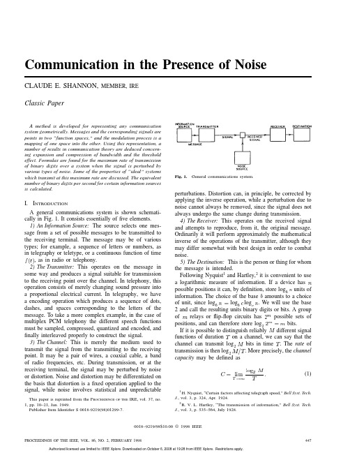
Communication in the Presence of Noise CLAUDE E.SHANNON,MEMBER,IREClassic PaperA method is developed for representing any communicationsystem geometrically.Messages and the corresponding signals arepoints in two“function spaces,”and the modulation process is amapping of one space into the ing this representation,anumber of results in communication theory are deduced concern-ing expansion and compression of bandwidth and the thresholdeffect.Formulas are found for the maximum rate of transmissionof binary digits over a system when the signal is perturbed byvarious types of noise.Some of the properties of“ideal”systemswhich transmit at this maximum rate are discussed.The equivalentnumber of binary digits per second for certain information sourcesis calculated.I.I NTRODUCTIONA general communications system is shown schemati-cally in Fig.1.It consists essentially offive elements.1)An Information Source:The source selects one mes-sage from a set of possible messages to be transmitted tothe receiving terminal.The message may be of varioustypes;for example,a sequence of letters or numbers,asin telegraphy or teletype,or a continuous function of timeA precise meaning will be given later to the requirement of reliable resolution ofthe in cps starting at zero frequency,and that we are allowed to use this channel for a certain period oftime,and whose time functions liewithin theinterval,and to have the time functionvery small outside theintervalcontains no frequencieshigherthansecondsapart.This is a fact which is common knowledge in the communication art.The intuitive justification is that,if,it cannot change toa substantially new value in a time less than one-half cycle of the highest frequency,that is,1/2.Then.If welet(5)O n t h e l e f t a r e t h e v a l u e s o ft h c o e f fic i e n t i n a F o u r i e r -s e r i e s e x p a n s i o n o f t h e f u n c t i ona s a f u n d a m e n t a lp e r i o d .T h i s m e a n s t h a t t h e v a l u e s o f t h e s a m p l e s .T h u s t h e y d e t e r m i n e,a n d f o r l o w e r f r e q u e n c i e sd e t e r m i n e s t h e o r i g i n a l f u n c t i o nc o m p l e t e l y .T h e r e i s o n e a nd o n l y o nef u n c t i o n w h o s e s p e c t r u m i s l i m i t e d t o a b a n ds e c o n d sa p a r t .T h e f u n c t i o n c a nb e s i m p l y r ec o n s t r u s a m p l e s b y u s i n g a p u l s e o f t h e t y p es ina n d z e r o at ,i .e .,a t a l l o t h e r s a m p l e p o i n t s .F u r t h e r m o r e ,c o n s t a n t i n t h e b a ndt h s a m p l e .T h e n t h e f u n c t i ond oe s n o t s t a r ta t z e r o f r e q u e n c yb u t a t s o m e h i g h e r v a l u e ,p r o v e d b y a l i n e a r t r a n s l a t i o n (c o r r e s p o nd i n s i n g le -s i d e b a n d m o d u l a t i o n )of t h e z e r o -f r e q t h i s c a s e t h e e l e m e n t a r y p u l s e i s o b t a i n e d f ra n d t h es a m p l e s a r e s p a c e d 1/2i f ,a n d o n l y i f ,a l l t h e s a m p l e s o u t s i d e t h i s i n t e r v a l a r e e x a c w e c a n s a y t h a t a n y f u n c t i o n l i m i t e d t o t h ebn u m b e r s .T h e o r e m 1h a s b e e n g i v e n p r e v i o u s l y i n o t b y m a t h e m a t i c i a n s 3b u t i n s p i t e o f i t s e v i d e n t i m p o r s e e m s n o t t o h a v e a p p e a r e d e x p l i c i t l y i n t ho f c o m m u n i c a t i o n t h e o r y .N y q u i s t ,4,5h o w e v e r ,a n d m o r er e c e n t l y G a b o r ,6h a v e p o i n t e d o u t t h a t a p p r o x i m a t e l.T h i s g i v e n a nd.T h e s l i g h t d i s c r e p a n c y i s d u e t o tt h a t t h e f u n c t i o n s o b t a i n e d i n t h i s w a y w i l l n l i m i t e d t o t h e b a nds e c o n d s i n c o n n e c t i o n w i t h t e l e g r a p h y ,a n d wt h e N y q u i s t i n t e r v a l c o r r e s p o n d i n g t o t h e b aTheindependent numbers associated with thefunction can be used to describe it.III.G EOMETRICAL R EPRESENTATION OF THE S IGNALSA set of threenumbers,,,regardless of their source,can always be thought of as coordinates of a point in three-dimensional space.Similarly,thedimensions.Each particularselection of these numbers corresponds to a particular point in this space.Thus there is exactly one point corresponding to each signal in thebandwill be,in general,veryhigh.A 5-Mc television signal lasting for an hour would be represented by a point in a spacewithdimensions.Needless to say,such a space cannotbe visualized.It is possible,however,to study analytically the propertiesof]by a simple entity (a point)in acomplex environment((8)whereisthesin(12)where.Similarly,the distance between two pointsis,these will correspond to points within a sphere ofradius(13)If noise is added to the signal in transmission,it means that the point corresponding to the signal has been moved a certain distance in the space proportional to the rms value of the noise.Thus noise produces a small region of uncertainty about each point in the space.A fixed distortion in the channel corresponds to a warping of the space,so that each point is moved,but in a definite fixed way.In ordinary three-dimensional space it is possible to set up many different coordinate systems.This is also possible in the signal spaceofcan be expanded as a sum of sines andcosines offrequenciesdimensions with theset of possible signals.In a similar way one can associate a space with the set of possible messages.Suppose we are considering a speech system and that the messages consistSHANNON:COMMUNICATION IN THE PRESENCE OF NOISE449Fig.2.Reduction of dimensionality through equivalence classes.of all possible sounds which contain no frequencies over a certainlimit;thatis,the total amplitude for this frequency.The reduction infrequency discrimination of the ear as frequency increasesindicates that a further reduction in dimensionality occurs.The vocoder makes use to a considerable extent of theseequivalences among speech sounds,in thefirst place byeliminating,to a large degree,phase information,and inthe second place by lumping groups of frequencies together,particularly at the higher frequencies.In other types of communication there may not be anyequivalence classes of this type.Thefinal destination issensitive to any change in the message within the fullmessage spaceoflimited to theband,which will,of course,be less than or equalto450Table1Fig.3.Mapping similar to frequency modulation.number of dimensions.Single-sideband amplitude modula-tion is an example of this type and an especially simple one,since the coordinates in the signal space are proportional to the corresponding coordinates in the message space.In double-sideband transmission the signal space has twice the number of coordinates,but they occur in pairs with equal values.If there were only one dimension in the message space and two in the signal space,it would correspond to mapping a line onto a square so that thepointof the messagespace may be lessthandimension in the signal space for a goodmapping.To make this saving it is necessary,of course,to isolate the effective coordinates in the message space,and to send these only.The reduced bandwidth transmission of speech by the vocoder is a case of this kind.The question arises,however,as to whether further reduction is possible.In our geometrical analogy,is it possible to map a space of high dimensionality onto one of lower dimensionality?The answer is that it is possible,with certain reservations.For example,the points of a square can be described by their two coordinates which could be written in decimalnotation(14)From these two numbers we can construct one number by taking digits alternatelyfrom(15)A knowledgeofdetermines determinesboth .Thus there is a one-to-one correspondence between the points of a square and the points of a line.SHANNON:COMMUNICATION IN THE PRESENCE OF NOISE451This type of mapping,due to the mathematician Cantor,can easily be extended as far as we wish in the direction of reducing dimensionality.A spaceofThere is a sense in which thisstatement is true,and another sense in which it is false.It is not possible to map the message space into the signal space in a one-to-one,continuous manner (this is known mathematically as a topological mapping)unless the two spaces have the same dimensionality;i.e.,unless.Hence,if we limit the transmitter and receiverto continuous one-to-one operations,there is a lower bound to theproduct in the channel.This lower bound is determined,not by theproduct of message bandwidth and time,but by the number of essentialdimension,and thatit is added to the transmitted signal to produce the received signal.A white thermal noise has the property that each sample is perturbed independently of all the others,and the distribution of each amplitude is Gaussian with standarddeviation is the average noise power.How many different signals can be distinguished at the receiving point in spite of the perturbations due to noise?A crude estimate can be obtained as follows.If the signal has apower.The number of amplitudes that can be reasonably well distinguishedisis a small constant in the neighborhood ofunity depending on how the phrase “reasonably well”is interpreted.If we require very goodseparation,to be larger.Since intime independent amplitudes,the total number of reasonably distinct signalsislogbe the average transmitter power,andsuppose the noise is white thermal noise ofpower.By sufficiently complicated encoding systems itis possible to transmit binary digits at aratelogwith as small a frequency of errors as desired.It is not possible by any encoding method to send at a higher rate and have an arbitrarily low frequency of errors.This shows that theratebut reduceerrors by using more involved encoding and longer delays at the transmitter and receiver.The transmitter will take long sequences of binary digits and represent this entire sequence by a particular signal function of long duration.The delay is required because the transmitter must wait for the full sequence before the signal is determined.Similarly,the receiver must wait for the full signal function before decoding into binary digits.We now prove Theorem 2.In the geometrical represen-tation each signal point is surrounded by a small region of uncertainty due to noise.With white thermal noise,the perturbations of the different samples (or coordinates)are all Gaussian and independent.Thus the probability of a perturbation havingcoordinates (these are the differences between the original and received signal coordinates)is the product of the individual probabilities for the differentcoordinatestimes the averagenoise power during thetimeincreases,thisaverage noise power mustapproach,the perturbation will almost certainly be to some point near the surface of a sphere ofradiussufficiently large we can insure (with probability as near to one as we wish)that the perturbation will lie within a sphere ofradiuswhere is very large.The received signals have an averagepower,and in the same sense must almost all lie onthe surface of a sphere ofradius-dimensionalsphere 8ofradiusof distinguishablesignalsislogwhenbinary digits is taken in at the trans-mitter.Thereare .Thus thereare different signal functions.When the sequenceofpossible transmitted signals and selects the one which is nearest the perturbed signal (in the sense of rms error)as the one actually sent.The receiver then constructs,as its output,the corresponding sequence of binary digits.There will be,therefore,an overall delayof seconds.To insure a frequency of errors lessthan signal functions must be reasonably well separated from each other.In fact,we must choose them in such a way that,when a perturbed signal is received,the nearest signal point (in the geometrical representation)is,with probability greaterthan ,the actual original signal.It turns out,rather surprisingly,that it is possible to chooseourdifferent samples of band-limited white noise withpowerpoints in the sphere corre-sponds to a particular encoding system.The general scheme of the proof is to consider all such selections,and to show that the frequency of errors averaged over all the particular selections is lessthanFig.5.The geometry involved in Theorem2.particular selections in the set with frequency of errors lessthan,receivedsignalis the regionof possible signals that might havecausedis of smallervolume than a sphere ofradiusby equating the area of thetriangle,calculated twodifferentways)lyinginsignal points.Hence theprobabilityareoutside(24)When these points areoutsidegreaterthan,thefrequency of errors will be lessthanispositive.Consequently,(25)will be trueif(27)orloglog,we can satisfy this bytakinglog.We can also send at therate.This completes the proof.VIII.D ISCUSSIONWe will call a system that transmits without errors at theratelogthe number of bitsper cycle of band vertical.The circles represent PCMsystems of the binary,ternary,etc.,types,using positiveand negative pulses and adjusted to give one error inaboutparison of PCM and PPM with ideal performance.three,etc.,discrete positions for the pulse.9The difference between the series of points and the ideal curve corresponds to the gain that could be obtained by more involved coding systems.It amounts to about 8dB in power over most of the practical range.The series of points and circles is about the best that can be done without delay.Whether it is worth while to use more complex types of modulation to obtain some of this possible saving is,of course,a question of relative costs and valuations.Thequantitylog ,the number of bits that can be transmitted intime,can be altered at will without changing the amount of information we can transmit,providedlog,the noisepowerwherelog ,i.e.,and is known as Gaussiannoise.We can calculate the capacity of a channel perturbed by any Gaussian noise from the white-noise result.Suppose our total transmitter poweris(32)since,for each elementary band,the white-noise result applies.The maximum rate of transmission will be found bymaximizinglog(34)or.For frequencieswhere the noise power is low,the signal power should be high,and vice versa,as we would expect.The situation is shown graphically in Fig.8.The curve is the assumed noise spectrum,and the three lines correspond to different choicesof is small,we cannotmakeFig.8.Best distribution of transmitter power.zero at other frequencies.With low valuesofin the band.X.T HE C HANNEL C APACITY WITH AN A RBITRARY T YPE OF N OISEOf course,there are many kinds of noise which are not Gaussian;for example,impulse noise,or white noise that has passed through a nonlinear device.If the signal is perturbed by one of these types of noise,there will still be a definite channelcapacity(35)be the probability that these amplitudes liebetweenand ,etc.Then thefunction successive samples are concerned.Theentropy(37)This limit exists in all cases of practical interest,and can be determined in many ofthem.,the entropyisexp(39)whereacts very much like a whitenoise ofpowerhavepoweris thenboundedbyis the average signal powerandlogapproaches the upper limit.XI.D ISCRETE S OURCES OF I NFORMATIONUp to now we have been chiefly concerned with the channel.Thecapacityletter is often followedbyis the probability of the sequence of symbols,and the sum is over all sequencesof(43)It turns outthatmessage symbols into sequences of binary digits in such a way that the average number of binary digits per message symbol is approximately anda discrete source ofentropy,,,,and successive letters are chosen independently,thenlogand the information produced is equivalent to 1.294bits for each letter of the message.A channel with a capacity of 100bits per second could transmit with bestencodingmessage letters per second.XII.C ONTINUOUS S OURCESIf the source is producing a continuous function of time,then without further data we must ascribe it an infinite rate of generating information.In fact,merely to specify exactly one quantity which has a continuous range of possibilities requires an infinite number of binary digits.We cannot send continuous information exactly over a channel of finite capacity.Fortunately,we do not need to send continuous messages exactly.A certain amount of discrepancy between the orig-inal and the recovered messages can always be tolerated.If a certain tolerance is allowed,then a definite finite rate in binary digits per second can be assigned to a continuous source.It must be remembered that this rate depends on the nature and magnitude of the allowed error between original and final messages.The rate may be described as the rate of generating information relative to the criterion of fidelity .Suppose the criterion of fidelity is the rms discrepancy between the original and recovered signals,and that we can tolerate avalue,entropypower of generating information in bits per second is boundedby(44)whereanda source whose rate of generatinginformation,it is possible to encode the source insuch a way as to transmit over this channel with the fidelitymeasuredby,this is impossible.In the case where the message source is producing white thermalnoise,.Hence the two bounds are equaland .We can,therefore,transmit white noise ofpowerperturbed by a white noise ofpower(45)A PPENDIXConsider the possible sequencesofth message is encodedbyexpandinglog(46)Probable sequences have short codes and improbable ones long codes.Wehave(48)or(49)The average number of binary digits used per message symbolis,.SHANNON:COMMUNICATION IN THE PRESENCE OF NOISE457Authorized licensed use limited to: IEEE Xplore. Downloaded on October 6, 2008 at 19:28 from IEEE Xplore. Restrictions apply.。
噪音的英文作文范文I hate noise. It's like a constant assault on my ears, never giving me a moment of peace. Whether it's the soundof traffic outside my window, the blaring music from my neighbor's apartment, or the never-ending chatter of people in a crowded place, it's all just too much for me to handle.Sometimes I wish I could just escape to a quiet, secluded place where I can be alone with my thoughts. A place where the only sound is the gentle rustling of leaves in the wind or the soothing chirping of birds. But intoday's world, finding such a place seems like animpossible dream.I've tried using earplugs and noise-cancelling headphones, but they can only do so much to block out the cacophony of the world around me. It's like I'm constantly fighting a losing battle against the never-ending barrageof sound.The worst part is that noise doesn't just affect me physically, but mentally as well. It's like a constant distraction that makes it impossible for me to concentrate or relax. I feel like I'm always on edge, never able to fully let my guard down.I envy those who seem unfazed by noise, who can go about their lives without being bothered by the constant racket. I wish I could be more like them, but for now, I'll just have to continue struggling to find moments of peace amidst the chaos.。
BTCPower AN01Ripple and NoiseR ipple is the output voltage fluctuation associated with the switching of the converter.Each switchingtransition pumps energy to the output, which causes it to rise a little.The typical switching frequency used in IMT converter is 250 to 350KHz.Therefore, the output noise frequency is in the 500KHz to 700KHz range. Typical value of the ripple is 1% to 2% of output.Noiseon the other hand, are higher frequency components, commonly known as ‘spikes’.Reduction of these ‘spikes’noise can be achieved by adding a 1µF ceramic chip capacitor and a 100µF tantalum capacitor in parallel to the +OUT and -OUT near the load.See Figure 10.Figure 10.Capacitor in Parallel ConnectionFigure 11.Ripple and Noise Chart Measuring Output Noise and RippleMeasuring output noise and ripple requires a basic understanding of the high frequency nature of noise.Very often, ‘noise’(as commonly measured) is actually the vector sum of common and differential mode noise. Common mode noise is common to both outputs ( i.e+OUT and -OUT) with respect to chassis or earth ground. Differential mode noise is found at one output with respect to the other.While the system load can be affected by differential mode noise, it is seldom affected by common mode noise.The common mode noise is often only created in the process of measuring the differential mode noise.Noise can be measured as root mean square (RMS) or peak to peak.Low frequency noise with a low peak to average ratio is often measured as RMS.High frequency spike noise is measured more accurately with an oscilloscope as peak to peak noise (Figure 11).Accurate measurement of output noise and ripple requires special attention to equipment used, measuring probes and the understanding of noises.The dc/dc converter switches large amount of output power when compared to the amplitude of the noise being measured.This means that even a few inches of open ground wire in the oscilloscope probe may pick up a fraction of a volt of noise if these probes are not properly connected to the measurement point.The preferred test to measure noise and ripple includes a custom probe made from a length of RG58A/U coaxial cable.It is connected to the oscilloscope with a BNC ‘T’connector, which is terminated with a 47 W carbon composition resistor in series with a 0.68µF Z5U capacitor. The other end of the coaxial is left bare.See Figure 12.Figure12.Set up for Measuring Noise and RippleBTCPower AN01Measure noise as closely as possible to the converter’s output terminals to reduce noise pick up.If an oscilloscope probe must be used, it must be set up for high frequency measurements.The greatest source of error is usually the unshielded portion of the oscilloscope probe.Voltage errors induced by magnetic radiation in the loop can easily suppress the actual values.T o reduce measurement errors, keep unshielded leads as short as possible.To prepare the probe for high frequency measurement, first remove the clip-on ground wire and the probe body fishhook adapter.Then attach a special tip and ground lead assembly as shown in Figure 13.Figure 13.High Frequency Measurement Set Up.To determine the presence of common mode noise, connect both the tip and the ground lead of the oscilloscope to the -OUT pin.The appearance of waveform on the screen suggests the presence of common mode noise.Such noise may be eliminated or reduced as suggested below:1) Wrap the oscilloscope probe lead several timesaround a large diameter Nickel Zinc ferrite toroid(permeability about 1600).This will act as a balun orcommon mode inductor.It increases common modeimpedance without significantly increasing differential mode impedance.2)Isolate the oscilloscope power source from the linevoltage with an isolation transformer.3) Wrap the power source AC line cord several timesaround a large diameter nickel zinc ferrite toroid.This will also reduce the common mode current.4) Do not use the ground lead clipped to most commonoscilloscope probes.The loop of wire itself will pick up the high frequency radiated noise and will giveerroneous readings.Measuring Equipment Set upThe power supply to the converter should be mounted about 1" away from the ground shield (or ground plane) which consist of a aluminium or copper sheet.The dimension of the aluminium or copper sheet should be at least as large as the power supply itself.If the power supply is provided with a ‘L’bracket, this can be served as the ‘ground’plane.Chassis grounding points on the PCB where the converters is mounted, including the ‘green wire’terminal for the line input ground lead, should be electrically connected to this shield with a short conductor no more than 2”long.The ground plane should be electrically connected to the conduit or the ground of a 3 prong safety plug.The set up above is very important to ensure that the noise from the power supply itself does not interfere with the measurement.Measuring of the noise and ripple is made with the output return connected to the ground plane.If the power supply has more than one return, all the returns should be connected to the ground plane.Measurement ProcedureA 12" of twisted #16AWG wire with a 47µF capacitor at an appropriate voltage rating and polarity is conencted to an output terminal and return.The noise measurement is taken across the capacitor with a 50 Mhz or greater bandwidth oscilloscope.See Figure 14.The ground lead should be as short as possible, preferrably the type which clips onto the barrel of the probe at one end of the probe body.Figure14.Noise Measurement ProcedureConnecting the dc/dc converterSet up the dc/dc converter as shown in Figure 15.Figure15.Converter Set UpBTCPower AN01Two 2.2nF / 250 Vac ‘Y’capacitor are connected between each of the inputs ( -IN and +IN) to the base plate.The base plate as well as the attached heat sink should have a solid connection to the ground plane.The purpose of the Y-caps is to provide a balanced low impedence path to ground for the common mode noise.BTCPower has a specially designed fixture for measuring these noise and ripple.This is shown in Figure 16.This fixture consist of a coaxial like cable with a #16AWG wire inside a cylindrical copper shield.The #16 wire is connected to the +OUT and the copper shield is connected to the -OUT. A ‘BNC’connector is used to connect the coaxial cable to the oscilloscope.With this arrangement, minimum loop is obtained and accurate measurements can be achieved.Note that a 47µF capacitor still needs to be connected across the -OUT and +OUT pins.BTCPower’s evaluation boards have the above fixture installed to facilitate easy measurements of the output noise and ripple.Please call the factory to obtain these boards.These board can also be used to evaluate the performance of IMT converters.See Figure17 for Evaluation Boards.Figure 17.BTC Evaluation Boards Measuring Noise and Ripple using BTCPower’s Evaluation Board.Obtain a 1:1 coaxial cable with a female BNC connector at each end. A ceramic capacitor of 0.68uF connected in series with the 50 Ohms resister is installed at the BNC located at the oscilloscope end of the coaxial cable.Please see Figure18.The purpose of the capacitor is to block the DC power from dissipating in the resistor.If the DC voltage being measured is less than 5 volts and a 1 Watt carbon composition resistor is used, the capacitor may not be needed.In this case, just a 50 ohm resistor is connected to reduce power dissipation caused by the DC component.In addition, there is potential for a ground loop to be formed from AC power ground connecting to Oscilloscope probe ground.To check this problem, connect the probe tip and its ground to the -OUT of the dc/dc converter.If there are signals generated on the scope, then the common mode noise due to this ground loop exists.In such a case, an isolation transformer is needed for the oscilloscope.A good isolation transformer must have the primary and secondary on separate bobbin, with ground shield between them.Alternatively, use a differential probe such as the T ektronix 5200 for accurate measurements.Picture16.SpecialFixture forMeasuring NoiseRippleFigure 18.Special Coaxial Cable。
June1,1997/Vol.22,No.11/OPTICS LETTERS799 Noiselike pulses with a broadband spectrumgenerated from an erbium-doped fiber laserM.Horowitz,Y.Barad,and Y.SilberbergDepartment of Physics of Complex Systems,Weizmann Institute of Science,Rehovot76100,IsraelReceived January2,1997An erbium-doped fiber laser that produces a train of intense noiselike pulses with a broadband spectrum anda short coherence length is reported.The noiselike behavior was observed in the amplitude as well as inthe phase of the pulses.The maximum spectral width obtained was44nm.The high intensity and theshort coherence length of the light were maintained even after propagation through a long dispersive fiber.A theoretical model indicates that this mode of operation can be explained by the internal birefringence ofthe laser cavity combined with a nonlinear transmission element and the gain response of the fiber amplifier.©1997Optical Society of AmericaDuring the past few years,lasers based on erbium-doped fiber amplifiers have been intensively investi-gated.Such lasers are compatible with semiconductor pump lasers and can generate light in a well-confined diffraction-limited mode.Several laser configura-tions were suggested and demonstrated for ultrashort pulse sources1as well as narrow-band cw lasers.2For several important applications,in particular in op-tical metrology,light sources with short coherence lengths are essential.LED’s,which generate broad-band noise,are commonly used for such applications; however,the power of LED’s is limited.Optical amplifiers such as erbium-doped fibers have been as spontaneous-emission sources or as light amplifiers to LED’s.However,the power of such sources is limited because of the continuous mode of operation of the device.A further increase in the optical power could improve the performance of optical systems that use such sources.In this Letter we report a pulsed erbium-doped fiber laser that generates a train of high-intensity,broadband,noiselike pulses.A theoretical model indicates that this mode of operation can be explained by the internal birefringence of the laser cavity combined with a nonlinear transmission element and the gain response of the fiber amplifier.Figure1shows the laser configuration schemati-cally.We used a modified ring fiber cavity,simi-lar to those used for passive mode locking through nonlinear polarization rotation,3which contained an erbium-doped fiber,two polarization controllers,a po-larizer,and an isolator.We found that a second polarizer between the polarization controllers was needed to control and to broaden the spectrum of the laser.This element provides additional intracav-ity pulse shaping4and helps to produce a smooth and broad spectrum.We achieved noiselike generation in a long cavity͑ഠ15m͒with a significant birefringence that was caused by the erbium-doped fiber and by winding some of the cavity fibers.In most of our experiments the overall dispersion was significantly positive because of inclusion of a3-m section fiber with positive group dispersion͓d75ps͑͞nm͞km͔͒. Although noiselike behavior could have been achieved without it,we found that positive dispersion improved the stability of the laser.The laser was pumped with a master-oscillator power-amplifier laser with a wavelength of985nm.When the laser was pumped above threshold,we observed a train of pulses with a repetition rate of 6.7MHz and a pulse duration of the order of100ps by using a fast detector and a sampling scope.The laser output was polarized and had an average power ofϳ10mW and a peak power ofϳ15W.We could change the pulse width by adjusting the polarization controllers or by changing the pump power.However, long and noiselike pulses were generated,even at pump powers close to the threshold.We could obtain shorter noiselike pulses with widths of the order of tens of pi-coseconds by changing the length of the positive disper-sion fiber.The optical spectrum,shown in Fig.2(a), was broad and smooth.The background-free second-harmonic autocorrelation trace shown in Fig.2(b)con-sisted of a190-fs peak riding upon wide and smooth shoulders that extended over the entire width of our measurement window of20ps.The ratio between the peak intensity and the shoulder level of the autocorre-lation trace was close to2.The maximum spectrum width obtained was44nm[Fig.2(c)].We stress that broad and smooth spectra were obtained only after we inserted the additional intracavity pulse shaping.The optical spectrum and the autocorrelation trace indicate that the laser generates noiselike pulseswith Fig.1.Schematic setup of the laser:PC’s,polarization controllers;P’s,polarizers;ISO,isolator;DCF,positive-dispersion fiber;Er,erbium-doped fiber amplifier.0146-9592/97/110799-03$10.00/0©1997Optical Society of America800OPTICS LETTERS/Vol.22,No.11/June1,1997Fig.2.(a)Optical spectrum and(b)the corresponding background-free autocorrelation trace of the laser output.(c)Spectrum with the maximum spectral width that was obtained.low coherence lengths and broad spectra.The auto-correlation measurement was noncollinear and there-fore was affected only by the intensity of the light and not by its phase.The ratio of2between the peak in-tensity and the shoulder level of the autocorrelation trace indicates that the power of the noiselike part of the pulse intensity is similar to the average pulse power.Therefore we can conclude that most of the pulse amplitude consists of noise and does not have a significantly ordered structure.We believe that the phase of the pulse has noiselike behavior similar to that measured for the amplitude.Indeed,the maxi-mal spectral width that was measured corresponds to a coherence time ofϳ50fs.Note that a figure-8-shaped fiber laser was reported to operate in a long-pulse mode,5which was attributed to modulational instabil-ity.However,modulational instability normally leadsto structured spectra and autocorrelation traces,which we did not observe in our experiments.The narrow peak in the autocorrelation trace wasmaintained even after the pulses propagated through a long dispersive medium.For example,after apulse passed through700m of a standard fiber ͓d216ps͑͞km͞nm͔͒,the half-width of the autocor-relation peak increased from190to380fs and thepeak value decreased by approximately a factor of2.A transform-limited pulse with a similar bandwidth is expected to broaden by more than3orders of mag-nitude after propagating through a similar fiber,and the maximum intensity of the autocorrelation trace would be attenuated by6orders of magnitude.We believe that the phase distortion caused by the fiber dispersion is relatively weak compared with the initial noise of the pulses and therefore has only a small effect on the coherence.This property could be important for optical measurements that need to be carried out through long fibers.An interesting question is:What are the pulse-to-pulse changes in this laser or,equivalently,to what extent are the modes of this laser locked?The fixed repetition rate and the constant pulse envelope suggest at least partial mode locking.The transition from cw to pulsed operation is sudden;the spectrum becomes wide and continuous,suggesting the onset of mode locking.In cavities in which the overall dispersion was smallwe could switch between a noiselike mode of operationand a single-pulse mode by adjusting the polarization controllers.We verified that for noiselike operation the polarization controllers were set at midrange be-tween maximal and minimal transmissivity of the po-larizers for low-power signals.The birefringence in our laser was significant.Theeffect of the birefringence combined with the gainresponse of the amplifier could be experimentally observed when the laser was operated in a continuous mode.In this case we could control the laser frequency over a wide range,between1541and1565nm and near 1535nm,by adjusting the polarization controllers. The birefringence of fiber lasers was analyzed and used for controlling the frequency of a cw laser.6Because the birefringence inside our laser cavity is not uniform, the frequency dependence of the linear transmissivity of the cavity has a complex behavior.We estimate the average birefringence of our laser to be D n531026.To explain the formation of the pulsed noiselike oper-ation mode we modeled a laser that comprised three elements:a fiber(with dispersion and Kerr effect), an optical amplifier,and a nonlinear transmission ele-ment.The total dispersion wasϳ0.2ps͞nm.To ana-lyze the nonlinear element we used a simplified model for nonlinear polarization rotation in a birefringent fiber.7,8The power of linearly polarized light trans-mitted through a birefringent fiber and a polarizer is given by8P tP0sin2͓͑f NL1f0͒͞2͔sin2͑2u͒,(1)June1,1997/Vol.22,No.11/OPTICS LETTERS801Fig.3.(a)Calculated time-dependent intensity and(b) autocorrelation trace obtained by numerical solution of the theoretical model after300iterations.where P0is the input power;u is the angle between the polarization of the incident wave and one of the principal axes of the fiber(denoted x and y);f0k0͑n x2n y͒l is the phase difference induced by thefiber birefringence,where n x and n y are the refractive indices for light polarized along the x and the y axes, respectively;k0is the wave number in vacuum;l is the fiber length;and f NLg l͑P x2P y͒͞3is the non-linear phase difference,where P x and P y are powers of the light components polarized along the x and the y axes and is g the nonlinear coefficient.Assuming a peak intracavity power of P150W and a nonlinear coefficient of g4W21km21,the interaction length needed for a nonlinear phase shift of p between the two polarization components isϳ15m.In our laser the birefringence is significant,and polarization-dependent delay(PDD)should be in-cluded.We included it in the frequency domain, where each frequency component was assigned a different bias phase delay f0.The model also in-cluded the spectral dependence of the amplifier.We took these effects into account by transforming the nonlinear transmissivity into the frequency domain, adding the frequency dependence of the transmission, and then transforming the result back into the time domain.The nonlinear phase shift was calculated in the time domain,but,to simplify our calculations,we did not include the PDD.A more precise model,which includes a more accurate modeling of the nonlinear polarization rotation,9has been described.We expectthe same general behavior to be reproduced.Figure3shows the time-dependent intensity and the calculated autocorrelation trace obtained by inte-gration of the laser equations numerically.We usedspontaneous emission,modeled as white noise,to initi-ate the oscillation.Noiselike behavior,similar to thatmeasured in the experiments,was obtained after a fewiterations.Our calculations reproduce the noiselike intensity,which leads to an autocorrelation trace witha narrow coherent peak and wide shoulders.Note thatthe noise is leading to nearly full modulation of the laser intensity.To simplify the calculations,we chosethe pulse duration in the simulations to be shorter thanthose measured in the experiments.Our laser cannot support short pulses because of thestrong positive dispersion and the significant birefrin-gence,which introduces significant PDD.Dispersion tends to broaden short pulses,and birefringence splitsthem through PDD.However,our laser does not sup-port long,narrow-band pulses because of the frequency dependence of the nonlinear element transmissivity ascaused by the birefringence and by the gain responseof the amplifier.Long,narrow-band pulses tend to be unstable owing to the growth of noise components thatare added to the pulses and have a bias phase͑f0͒that causes high nonlinear differential gain.Hence the only stable mode of operation available is the for-mation of noiselike bursts,as we have observed experi-mentally and theoretically.We have reported a new erbium-doped fiber laserthat produced a train of long noiselike100-ps pulseswith a unique broad spectrum as wide as44nm. Such a wide spectrum is useful in many applica-tions in metrology for which low coherence is re-quired.Unlike most other sources for low-coherence light,this laser output is produced with relatively high peak power in well-defined pulses.We believe that this new source will offer these advantages for many applications in fiber-optics measurements and other fields.This research was supported in part by a grant fromthe Israeli Ministry of Science.References1.M.E.Fermann,Appl.Phys.B58,197(1994).2.M.Horowitz,R.Daisy,B.Fischer,and J.L.Zyskind,Opt.Lett.19,1406(1994).3.H. A.Haus, E.P.Ippen,and K.Tamura,IEEE J.Lightwave Technol.30,200(1994).4.G.P.Agrawal,Nonlinear Fiber Optics,2nd ed.(Aca-demic,San Diego,Calif.,1995),p.247.5.R..H.Stolen,J.Botineau,and A.Ashkin,Opt.Lett.7,512(1982).6.K.I.Kitayama,Y.Kimura,and S.Seikai,Appl.Phys.Lett.46,317(1985).7.H.G.Winful,Opt.Lett.11,33(1986).8.D.J.Richardson,ming,D.N.Payne,V.Matsas,and M.W.Phillips,Electron.Lett.27,542,730(1991).9.U.Ghera,N.Konforti,and M.Tur,IEEE Photon.Technol.Lett.4,4(1992).。