手压阀说明书
- 格式:doc
- 大小:3.53 MB
- 文档页数:25
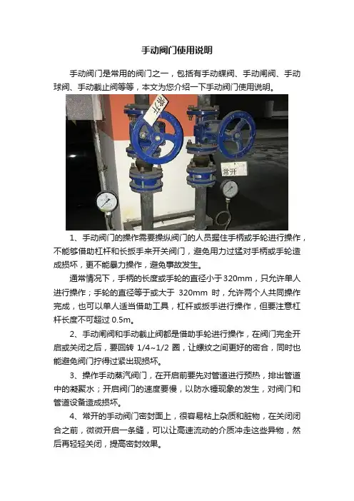
手动阀门使用说明
手动阀门是常用的阀门之一,包括有手动蝶阀、手动闸阀、手动球阀、手动截止阀等等,本文为您介绍一下手动阀门使用说明。
1、手动阀门的操作需要操纵阀门的人员握住手柄或手轮进行操作,不能够借助杠杆和长扳手来开关阀门,避免用力过猛对手柄或手轮造成损坏,更不能暴力操作,避免事故发生。
通常情况下,手柄的长度或手轮的直径小于320mm,只允许单人进行操作;手轮的直径等于或大于320mm时,允许两个人共同操作完成,也可以单人适当借助工具,杠杆或扳手进行操作,但要注意杠杆长度不可超过0.5m。
2、手动闸阀和手动截止阀都是借助手轮进行操作,在阀门完全开启或关闭之后,要回转1/4~1/2圈,让螺纹之间更好的密合,同时也能避免阀门拧得过紧出现损坏。
3、操作手动蒸汽阀门,在开启前要先对管道进行预热,排出管道中的凝聚水;开启阀门的速度要慢,以防水锤现象的发生,对阀门和管道设备造成损坏。
4、常开的手动阀门密封面上,很容易粘上杂质和脏物,在关闭闭合之前,微微开启一条缝,可以让高速流动的介质冲走这些异物,然后再轻轻关闭,提高密封效果。
5、在一些过高温介质的管道中,当手动阀门关闭之后,阀体内温度下降,因为热胀冷缩导致阀件收缩,密封面会出现一些细小的缝隙,阀门会出现泄漏。
在这种情况下,要在关闭手动阀门之后,过一会儿再关闭一次。
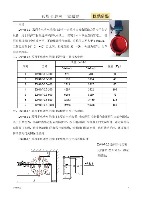
一、用途D940J-0.5系列手电动密闭阀门是有一定抗冲击波余压能力的专用防护设备,用于防护工程的进风和排风系统上,安装于水平或垂直的管道上,使用时要求阀门全启或全闭,不能作调节气流用。
公称压力不大于0.05MPa ,工作温度在-30°C —+40°C 之间,相对湿度30—40%,介质为空气,为单向闭路机构。
二、D940J-0.5系列手电动密闭阀门型号及主要技术参数三、D940J-0.5系列手电动密闭阀门结构特点及工作原理:D940J-0.5系列手电动密闭阀门主要由电动装置、电动阀门控制器和密闭阀门三部分组成;其工作原理为:当战时需要进行隔绝防护时,按下电动阀门控制器上的关阀按键,通过阀杆转动使阀门关闭,通过电动阀门的行程控制机构,锁紧阀门保证密封;也可转动手轮,通过阀杆转动使阀门关闭保证密封。
D940J-0.5系列手电动密闭阀门主要外形尺寸与连接尺寸:D940J-0.5系列手电动密闭阀门外型尺寸图:如左图所示:序号 型号 风量(m 3/h )重量(Kg )V=6m/s V=8m/s 1 D940J-0.5-200 678 904 31 2 D940J-0.5-300 1526 2034 48 3 D940J-0.5-400 2713 3617 67 4 D940J-0.5-500 4239 5652 106 5 D940J-0.5-600 6104 8139 75 6 D940J-0.5-800 10852 14469 126 7D940J-0.5-10001695622608160D940J-0.5系列手电动密闭阀门外型尺寸表(mm)规格L0 L1 L2 D D1 D2 n d DN200 672 118 472 270 215 250 8 9 DN300 781 145 521 385 315 360 9 11 DN400 945 175 598 515 441 490 12 12 DN500 1095 225 665 650 560 622 12 14 DN600 1081 275 706 750 666 720 12 14 DN800 1271 290 801 950 870 920 16 17 DN1000 1606 300 1016 1205 1090 1160 20 18 四、D940J-0.5系列手电动密闭阀门电动装置主要由电机、减速器、行程控制机构、转矩控制机构、开度指示机构、手轮和机械限位机构组成。
“MP-4”MANUAL RELAYMODEL 1901OPERATION MANUAL OMP # 1901 08/02 Revision 0I. PRINCIPLE OF OPERATIONThe Ruelco “MP-4” relay is a pilot operated manual relay. It is a three (3) way, normally closed valve with a palm knob for relay position indication and manual operation. In the closed position, pneumatic or hydraulic pressure coming into the “Inlet” port is locked from the “Outlet” port by the upper shaft o-ring. The spring keeps the spool in the down or closed position. The valve is opened by manually pulling the palm knob outward, thus moving the shaft assembly upward. The detent pin is then pushed “In” to lock the relay open until a pneumatic signal is applied to the pilot cap of the relay. This pneumatic pressure acting on the piston causes the detent pin to drop “Out” of the locked position. When the relay is in the open position, it causes the middle o-ring to engage the body seal bore and the upper o-ring to disengage from the body seal bore respectively. Supply pressure at the “Inlet” port may then flow through the body to the “Outlet” port.When the pneumatic signal is removed from the pilot supply “PS”, the spring moves the shaft assembly downward. This causes the upper O-ring to disengage the body seal bore. This also allows the middle O-ring to engage the body seal bore and prevent flow into the “IN” port. With the supply pressure blocked, pressure will flow from the “OUT” port and exit through the “VENT” port. The relay may also be closed manually by pushing the palm knob inward.II. INSTALLATIONThe “MP-4” can be mounted either vertically, horizontally, panel mounted (with optional panel mount nut), or supported by piping from any of its ports. If it is supported by piping, care should be taken that the strength of the pipe fittings used is adequate to prevent the fitting from breaking off in the relay body should the relay be inadvertently struck.Proper pipe thread sealant should be used on any pipe fittings threaded into the relay ports. If stainless steel fittings are used, a sealant that will prevent galling is required. Supply gas or hydraulic fluid flowing through the relay should be free of large dirt particles. If compressed air is used, it does not have to be lubricated. If natural gas is used, it should contain as little condensate as possible. This will extend the life of the seals.If the relay is going to be installed in a location where the stem will be exposed to excessive paint, sand, drilling fluids, etc., the use of the optional stem protector is recommended. The stem protector does not affect the operation of the relay and will prevent the relay from jamming should the exposed portion of the shaft accumulate excessive trash or debris.III. DISASSEMBLY (REFER TO SPEC.SHEET 1901)Tools required are as follows:• 7/16” open end wrench or suitable adjustable wrench•1” open end wrench or suitable adjustable wrench•7/8” open end wrench or suitableadjustable wrench and flat bladescrew driver (for removal ofoptional stem protector)A. PARTIALDISASSEMBLY1. To replace the three (3) shafto-rings (Item7) and the pistonseal (Item 11), the relay doesnot have to be completelydisassembled.2. Place the 7/16” wrench onthe lock nut and rotate itclockwise while holding theknob (Item 1) until the knobis loose. Rotate the knobcounterclockwise andremove it from the shaft sub-assembly . If the optionalstem protector is installed,pull the relay knob outwarduntil the flat on the sealwasher (Item 16) is visible.Use the 7/8” wrench to rotatethe seal washer clockwiseuntil the knob is loose.Remove the knob and sealwasher simultaneously(rotate counterclockwise).3. Remove the retaining ring(Item 13) from body (Item 8)in order to remove base(Item 14).4. Push the shaft subassemblythrough the valve body andslide the spring (Item 9) offthe relay shaft.5. The seals on the shaft maynow be replaced as perinstructions given in therepair section of this manual(IV.). B. FULLDISASSEMBLY1. Follow the procedures statedunder partial disassembly. Ifthe relay is panel mounted, itis not necessary to removethe relay from the panel, butit is recommended so thatadequate inspection andcleaning of all parts may beperformed.2. Using a flat blade screwdriver, remove the RetainingRing (Item 13) from the body(Item 8)3. Remove the base (Item 14),followed by the shaftsub-assembly.4. To remove the stemprotector housing (Item 16),use the flat blade screwdriver and rotate the screws(Item 4) counterclockwise.5. The relay is now ready to becleaned and repaired.IV. REPAIR AND ASSEMBLY1. Remove the piston and shaft sealsfrom the shaft assembly.2. Using an appropriate safety solvent,clean all parts.3. Inspect the shaft assembly for anymajor damage such as burrs andnicks. Also inspect it forstraightness. Replace the shaftassembly is damaged.4. Examine the relay body and head forany damage such as burrs, nicks,etc. Replace any damaged pieces.5. Replacement seals from a Ruelcoproduct repair kit are required forproper relay performance. It isrecommended that all seals belubricated before and afterinstallation with a high qualitysilicone base grease.6. Install the piston seal onto the shaftsubassembly. NOTE: This is a cuptype seal. The inside of the cupshould be facing toward the bottomof the shaft subassembly as shown.Be sure that the inside lip of the sealis completely pushed into the pistongroove.7. Lubricate the shaft o-rings and installon the shaft subassembly.8. Lightly lubricate the large bore in therelay body.9. Slide the spring over the shaftsubassembly and slide the shaft intothe relay body.10. Lubricate the base o-ring (Item 12)and install into the valve body.11. Insert the base in the body andsecure using the retaining ring.12. If a stem protector is to be used,locate the holes in the protectorbody over the threaded holes in thehead. Insert the two (2) screws androtate them clockwise to tighten.13. Thread the lock nut over the shaftsubassembly until it reaches the lastthread. Do not tighten. Rotate theknob over the shaft thread until ittouches the lock nut. Hold the knoband turn the lock nutcounterclockwise with the 7/16”wrench until firmly tightened.14. To install the stem protector washerand the knob, thread the washer asfar down onto the shaft as possible.Screw the knob onto the exposedthreads above the washer, but donot tighten. Pull the relay shaft fullyoutward and thread the protectorwasher until it stops. NOTE: Theprotector seal should now becompletely inside the protectorhousing. Release the relay knob andallow the shaft subassembly toretract. Rotate the knob clockwiseuntil it stops. Pull the knob outwardagain and use the 7/8” wrench toturn the protector washercounterclockwise until tight.V. RECOMMENDEDMAINTENANCE Procedure and IntervalOperate Manually – Every thirty (30) days.Disassemble, inspect and lubricate – Yearlyor as required.Replace all seals – Every two (2) years oras required.。
手压阀设计
一、工作原理
手压阀是开启或关闭液路的一种手动阀门。
手柄向下压紧阀杆时,弹簧受压,阀杆向下移动,使入口和出口相通,阀门打开;松开手柄,因弹簧力作用,阀杆向上压紧阀体,入口与出口不通,阀门关闭。
二、机构功能
手压阀用来控制流体的方向、压力、流量的装置。
阀门是使配管和设备内的介质液体、流动或停止、并能控制其流量的装置。
主要用于手动改变压力大小,从而达到手动变速的目的。
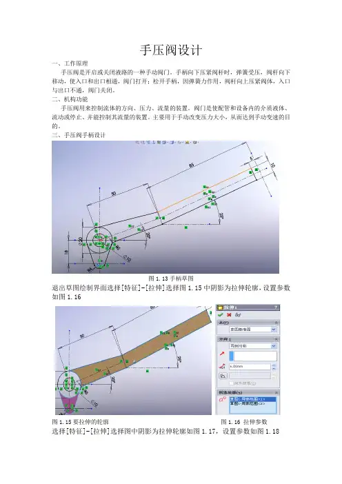
三、手压阀手柄设计
图1.13手柄草图
退出草图绘制界面选择[特征]-[拉伸]选择图1.15中阴影为拉伸轮廓,设置参数如图1.16
图1.15要拉伸的轮廓图1.16 拉伸参数
选择[特征]-[拉伸]选择图中阴影为拉伸轮廓如图1.17,设置参数如图1.18
图1.17拉伸3轮廓图1.18拉伸3参数
选择手柄端面为绘图面绘制直径为5的圆如图1.19
图1.19 直径为5的圆
退出绘图界面选择[特征]-[拉伸]以刚绘制的圆为轮廓深度为5mm拉伸出一个圆柱。
并选择[插入]-[注解]-[装饰螺纹线]以刚拉伸的圆柱端面外圆为圆形边线,次要直径为3.75mm深度为5mm绘制装饰螺纹线。
选择[特征]-[圆角]以拉伸1中的个边线为基准对实体进行倒圆角,最后选择材料为HT20绘制手柄如图1.20。
图1.20 手柄
四、创新点
在此次设计过程中将弹簧零件的绘制安排在其他各零件装配完成之后,通过采用上下两支撑面间的相对距离来定义弹簧的长度,从而使系统可以计算出弹簧在上下两个支撑面不同的状态下的长度,以此来实现弹簧的伸缩。
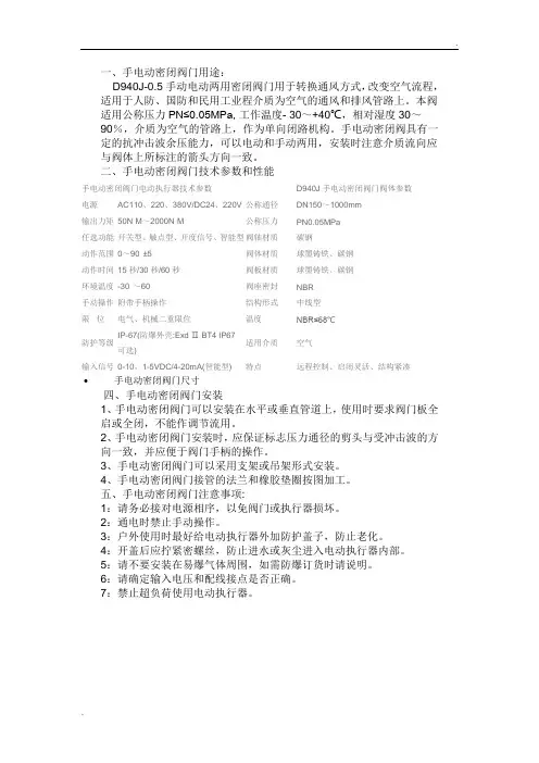
.. 一、手电动密闭阀门用途:D940J-0.5手动电动两用密闭阀门用于转换通风方式,改变空气流程,适用于人防、国防和民用工业程介质为空气的通风和排风管路上。
本阀适用公称压力PN≤0.05MPa,工作温度- 30~+40℃,相对湿度30~90%,介质为空气的管路上,作为单向闭路机构。
手电动密闭阀具有一定的抗冲击波余压能力,可以电动和手动两用,安装时注意介质流向应与阀体上所标注的箭头方向一致。
二、手电动密闭阀门技术参数和性能手电动密闭阀门电动执行器技术参数D940J手电动密闭阀门阀体参数电源AC110、220、380V/DC24、220V 公称通径DN150~1000mm输出力矩50N·M~2000N·M 公称压力PN0.05MPa任选功能开关型、触点型、开度信号、智能型阀轴材质碳钢动作范围0~90°±5°阀体材质球墨铸铁、碳钢动作时间15秒/30秒/60秒阀板材质球墨铸铁、碳钢环境温度-30°~60°阀座密封NBR手动操作附带手柄操作结构形式中线型限位电气、机械二重限位温度NBR≤68℃防护等级IP-67(防爆外壳:Exd Ⅱ BT4 IP67可选)适用介质空气输入信号0-10,1-5VDC/4-20mA(智能型) 特点远程控制、启闭灵活、结构紧凑•手电动密闭阀门尺寸四、手电动密闭阀门安装1、手电动密闭阀门可以安装在水平或垂直管道上,使用时要求阀门板全启或全闭,不能作调节流用。
2、手电动密闭阀门安装时,应保证标志压力通径的剪头与受冲击波的方向一致,并应便于阀门手柄的操作。
3、手电动密闭阀门可以采用支架或吊架形式安装。
4、手电动密闭阀门接管的法兰和橡胶垫圈按图加工。
五、手电动密闭阀门注意事项:1:请务必接对电源相序,以免阀门或执行器损坏。
2:通电时禁止手动操作。
3:户外使用时最好给电动执行器外加防护盖子,防止老化。
4:开盖后应拧紧密螺丝,防止进水或灰尘进入电动执行器内部。
Manually operated valvesManually operated valvesKey featuresInnovative Versatile Reliable Easy to install• Small and compact for a wide rangeof pneumatic applications• Numerous valve functions can beselected: 3/2-way and 5/2-wayfunctions• With flow rates of up to 600 l/min,the valves offer outstanding pneu-matic performance for a wide rangeof applications• Lightweight• Minimal actuating forces• Flexibility of the pneumatic workingports provides a practical solutionto different requirements• Round silencer for ducted exhaustair• Suitable for vacuum in some cases• Reverse operation possible in somecases• Actuation: direct• Pressure range from vacuum to10 bar possible• Versions:– Pushbutton valve– Toggle lever valve– Hand lever valve– Finger lever valve– Foot valve• Durable thanks to tried-and-testedpoppet valves• Sturdy thanks to metal or plastichousing and connecting thread orconnector• Front panel mounting or mountingon bracket2d Internet: /catalogue/...Subject to change – 2020/0732020/07 – Subject to changed Internet: /catalogue/...Manually operated valvesCharacteristics43[1] Finger lever, pushbutton, togglelever, button switch, foot pedal as actuator[2] Fast mounting: via retainingbracket or screwed directly via through-hole, front panel mount -ing possible in some cases[3] Practical connection via threadedconnection or connector [4] Various widthsEquipment options 3/2-way valve 5/2-way valve • Normally open/closed • Mechanical spring• Vacuum operation possible • Directly actuated • Ducted exhaust air •Detenting (bistable) or non-detenting (monostable)• Mechanical spring• Vacuum operation possible • Directly actuated • Ducted exhaust air •Detenting (bistable) or non-detenting (monostable)4d Internet: /catalogue/...Subject to change – 2020/07Manually operated valvesPeripherals overviewManually operated valves 3/2-way pushbutton valve13/2-way foot valve F-3_M5 ...3/2-way toggle lever valve KH/O-3-PK143Manually operated valves Key featuresManually operated valvesManually operated valves are used in all industrial sectors, as well as in the skilled trades. They are used to carry out simpleprocesses such as clamping or closingsafety doors.Depending on the required actuation(pushing, rotating/swivelling or tilting),the valves are either resetting ornon-resetting.The valves are directly actuated.5 2020/07 – Subject to change d Internet: /catalogue/...Manually operated valvesKey features-NoteH-A filter must be installed upstream of valves operated in vacuum mode. This prevents any foreignmatter in the intake air getting into the valve (e.g. when operating a suction cup with connector).6d Internet: /catalogue/...Subject to change – 2020/07Manually operated valves Data sheet – Pushbutton valve-M-Flow rate80 l/min-L- Pressure–0.95 ... 8 bar -Q-Temperature range–10 ... +60°C Mounting either via through-hole or onfront panel (in the case of F-3-M5 withflange eyes)F-3-M5M52.02357.0––1)PK-3 = barbed fitting for plastic tubing with 3 mm nominal widthH--NotePushbutton valves are only to be operated manually.7 2020/07 – Subject to change d Internet: /catalogue/...Manually operated valvesData sheet – Pushbutton valve8d Internet: /catalogue/...Subject to change – 2020/07Manually operated valves Data sheet – Toggle lever valve-M-Flow rateMounting via through-hole Array80 l/min-L- Pressure0 ... 8 bar-Q-Temperature range–10 ... +60°C1)9 2020/07 – Subject to change d Internet: /catalogue/...Manually operated valvesData sheet – Toggle lever valve10d Internet: /catalogue/...Subject to change – 2020/07-M-Flow rate80 ... 600 l/min -L- Pressure–0.95 ... 10 bar -Q-Temperature range–10 ... +60°CMounting via through-holeTH-3-1/4-B6003/2-way valvePoppet valve, directly actuatedG1/47.021010.5––1)PK-3 = barbed fitting for plastic tubing with 3 mm nominal width-M-Flow rate550 ... 600 l/min -L- Pressure–0.95 ... 10 bar -Q-Temperature range–10 ... +60°C Mounting either via through-hole or onfront panelH-3-1/4-B6003/2-way valvePoppet valve, directly actuatedG1/4320-M-Flow rate550 ... 600 l/min -L- Pressure–0.95 ... 10 bar -Q-Temperature range–10 ... +60°C Mounted via flange eyes on thehousingFoot valves with detent are actuated bymeans of a foot lever with mechanicaldetent. The valve engages when it isfirst actuated, and when the foot leveris actuated again, the valve returns toits normal position.F-3-1/4-B FO-3-1/4-B6003/2-way valvePoppet valve,directly actuatedPoppet valve,directly actuatedPoppet valve,directly actuatedG1/4G1/47.07.059559550.055.0Ordering data – Foot valveAccessories1)Packaging unitFesto - Your Partner in AutomationConnect with us/socialmedia 1Festo Inc.2Festo Pneumatic 3Festo Corporation 4Regional Service Center 5300 Explorer DriveMississauga, ON L4W 5G4CanadaAv. Ceylán 3,Col. Tequesquináhuac 54020 Tlalnepantla, Estado de México1377 Motor Parkway Suite 310Islandia, NY 117497777 Columbia Road Mason, OH 45040Festo Customer Interaction CenterTel:187****3786Fax:187****3786Email:*****************************Multinational Contact Center 01 800 337 8669***********************Festo Customer Interaction Center180****3786180****3786*****************************S u b j e c t t o c h a n g e。
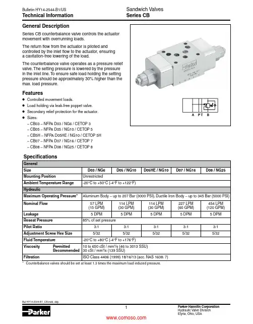
Technical InformationSeries CBGeneral DescriptionSeries CB counterbalance valve controls the actuator movement with overrunning loads.The return flow from the actuator is piloted and controlled by the inlet flow to the actuator, ensuring a cavitation-free lowering of the load.The counterbalance valve operates as a pressure relief valve. The setting pressure is lowered by the pressure in the inlet line. To ensure safe load holding the setting pressure should be approximately 30% higher than the max. load pressure.Features• Controlled movement loads.• Load holding via leak-free poppet valve.• Secondary relief protection for the actuator.• Sizes:– CB03 – NFP A D03 / NG6 / CETOP 3 – CB05 – NFP A D05 / NG10 / CETOP 5 – CB5H – NFP A D05HE / NG10 / CETOP 5H – CB07 – NFP A D07 / NG16 / CETOP 7– CB08 – NFPA D08 / NG25 / CETOP 8Ordering Information Series CBCounterbalanceValveCBCode Description AA in A BB in B DD in A and BCode Description03 NFPA D03 / NG6 05 NFPA D05 / NG10 5H* NFPA D05HE / NG10 07 NFPA D07 / NG16 08 NFPA D08 / NG25StyleSizePressure Range30C ode Description30 207 Bar (3000 PSI)**69 to 276 Bar (1000 to 4000 PSI)C ode Description A Aluminum DDuctile IronBody Material SealC ode Description N NitrileV* Fluorocarbon* Upon request.Weight:Size CB**AA30NA CB**AA30ND CB**BB30NA CB**BB30ND CB**DD30NA CB**DD30ND CB030.3 kg (0.8 lbs.) 1.1 kg (2.4 lbs.)0.5 kg (1.1 lbs.) 1.1 kg (2.4 lbs.)0.8 kg (1.7 lbs.) 1.5 kg (3.2 lbs.)CB05, CB5H 1.0 kg (2.3 lbs.) 2.2 kg (4.9 lbs.) 1.0 kg (2.3 lbs.)2.2 kg (4.9 lbs.) 1.5 kg (3.2 lbs.) 2.9 kg (6.4 lbs.)CB07 2.5 kg (5.6 lbs.)4.8 kg (10.6 lbs.) 2.5 kg (5.5 lbs.) 5.3 kg (11.8 lbs.) 3.6 kg (8 lbs.)7.3 kg (16.2 lbs.)CB085.3 kg (11.7 lbs.)11.8 kg (25.9 lbs.)5.9 kg (13.1 lbs.)13.3 kg (29.3 lbs.)7.9 kg (17.4 lbs.)16.2 kg (35.8 lbs.)CB**AA CB**BB CB**DD** Standard setting.* Valve comes with D05HE (ISO) pattern seal plate (990-120-012). If D05H pattern is required, order seal plate kit 990-120-009.CB03*CB05/CB5HCB03*CB05/CB5HCB03*CB05/CB5H1050602.613.215.930204070807.95.310.618.521.2Flow (Q)PSILPMGPMP r e s s u r e D r o p pD Pilot Pressure vs.Flow201060505.32.615.913.24030807010.67.921.218.5Flow (Q)LPMGPMP r e s s u r e D r o p pD Pressure Differential vs.Flow Fluid Viscosity 30 cSt at 50°C (122°F)1050602.613.215.930204070807.95.310.618.521.2Flow (Q)40PSI 80LPMGPM P r e s s u r e D r o p pD Pressure vs.Flow ReliefFluid Viscosity 30 cSt at 50°C (122°F)201001205.326.531.760408014016015.910.621.237.042.3Flow (Q)PSILPMGPMP r e s s u r e D r o p pD Pilot Pressure vs.FlowFlow (Q)P r e s s u r e D r o p pD 20605.315.9401208010010.631.721.226.5LPMGPMPressure Differential vs.Flow Fluid Viscosity 30 cSt at 50°C (122°F)201001205.326.531.7604080140160Flow (Q)40PSI 80LPMGPMP r e s s u r e D r o p pD Pressure vs.Flow ReliefFluid Viscosity 30 cSt at 50°C (122°F)CB07*CB08*CB07*CB08*CB07*CB08*4020024010.652.963.51208016028032031.721.242.374.184.7Flow (Q)PSI LPMGPMP r e s s u r eD r o p pD Pilot Pressure vs.FlowFlow (Q)P r e s s u r e D r o p pD 4012010.631.78024016020021.263.542.352.9LPMGPMPressure Differential vs.Flow Fluid Viscosity 30 cSt at 50°C (122°F)201001205.326.531.760408014016018020022015.910.621.237.042.347.652.958.2Flow (Q)40PSI 80LPMGPMP r e s s u r e D r o p pD Pressure vs.Flow ReliefFluid Viscosity 30 cSt at 50°C (122°F)25756.619.85012510013.233.126.5Flow (Q)200600PSI400800Bar LPMGPMP r e s s u r e D r o p pD Pilot Pressure vs.FlowFluid Viscosity 30 cSt at 50°C (122°F)20605.315.9401001208010.626.531.721.2Flow (Q)50LPMGPMP r e s s u r e D r o p pD Pressure Differential vs.Flow Fluid Viscosity 30 cSt at 50°C (122°F)20605.315.9401001208010.626.531.721.2Flow (Q)200PSIBar LPMGPMP r e s s u r e D r o p pD Pressure vs.Flow ReliefFluid Viscosity 30 cSt at 50°C (122°F)DimensionsCB03AA – Inch equivalents for millimeter dimensions are shown in (**)CB03BB –Inch equivalents for millimeter dimensions are shown in (**)Series CBDimensions Series CBSeries CB03DD – Inch equivalents for millimeter dimensions are shown in (**)CB05AA – Inch equivalents for millimeter dimensions are shown in (**)CB05DD – Inch equivalents for millimeter dimensions are shown in (**)CB5HBB –Inch equivalents for millimeter dimensions are shown in (**)* D05HE (Standard)** D05H* D05HE (Standard) Valve comes with D05HE (ISO) Pattern seal plate (990-120-012). If D05H pattern is required, order seal plate kit 990-120-009.Valve comes with D05HE (ISO) Pattern seal plate (990-120-012). If D05H pattern is required, order seal plate kit 990-120-009.CB07AA – Inch equivalents for millimeter dimensions are shown in (**)* D05HE (Standard)** D05Hseal plate kit 990-120-009.CB07DD – Inch equivalents for millimeter dimensions are shown in (**)CB08BB –Inch equivalents for millimeter dimensions are shown in (**)Parker Hannifin Corporation Hydraulic Valve Division 520 Ternes AvenueElyria, Ohio 44035 USATel: 440 366 5100Fax: 440 366 5253/hydraulicvalve Bulletin HY14-2544-B1/US,7/15© 2015 Parker Hannifin Corporation. All rights reserved.FAILURE OR IMPROPER SELECTION OR IMPROPER USE OF THE PRODUCTS DESCRIBED HEREIN OR RELA TED ITEMS CAN CAUSE DEA TH, PERSONAL INJURY AND PROPERTY DAMAGE.• This document and other information from Parker-Hannifin Corporation, its subsidiaries and authorized distributors provide product or system options for further investigation by users having technical expertise.• The user, through its own analysis and testing, is solely responsible for making the final selection of the system and components and assuring that all performance, endurance, maintenance, safety and warning requirements of the application are met. The user must analyze all aspects of the application, follow applicable industry standards, and follow the information concerning the product in the current product catalog and in any other materials provided from Parker or its subsidiaries or authorized distributors.• T o the extent that Parker or its subsidiaries or authorized distributors provide component or system options based upon data or specifications provided by the user, the user is responsible for determining that such data and specifications are suitable and sufficient for all applications and reasonably foreseeable uses of the components or systems.WARNING – USER RESPONSIBILITYThe items described in this document are hereby offered for sale by Parker-Hannifin Corporation, its subsidiaries or its authorized distributors. This offer and its acceptance are governed by the provisions stated in the detailed “Offer of Sale” elsewhere in this document or available at /hydraulicvalve.OFFER OF SALEFor safety information, see Safety Guide SG HY14-1000 at /safety or call 1-800-CParker.SAFETY GUIDE。
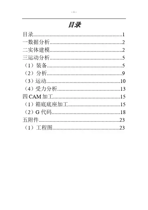
目录目录 (1)一数据分析 (2)二实体建模 (2)三运动分析 (5)(1)装备 (5)(2)分析 (9)(3)运动 (10)(4)受力分析 (13)四CAM加工 (15)(1)箱底底座加工 (15)(2)G代码 (18)五附件 (23)(1)工程图 (23)手压阀说明书一、数据分析1、图纸介绍:根据手压阀的轴侧图和零件图在A3纸上按1:1绘制装备图。
2、参数选择:开口销GB\T91-2000 4x18 公称直径d=4mm 长度l=50mm 材料Q235 不经表面处理螺纹:螺套M24 螺距p=2mm 中径D1=22.701mm 小径D2=21.835mm; 阀体M36螺距p=2mm中径D1=34.701mm 小径D2=33.835mm其他参数,详情见附件。
二、实体建模1球头:主要采用旋转等指令2垫片主要采用旋转等指令3螺套主要采用拉伸旋转等指令4销钉主要采用拉伸钻孔等指令5、箱座主要采用拉伸、旋转、伸出项(切口)等指令6、箱体主要采用拉伸、旋转、钻孔等指令7手柄主要采用拉伸旋转等指令三、机构运动分析1装备一、箱体装备:采用缺省约束二、手柄装备:采用销钉约束三、阀杆装备:采用圆柱和添加集轴承链接四、螺套装备:采用销钉连接五、销钉装备:采用缺省装备六、胶垫装备:采用缺省装备七、箱座装备:采用销钉和平面装备八、球头装备:采用缺省装备2分析一、伺服电动机二、弹簧系统三、阻尼3运动手压阀是吸气和排出液体的一种手动阀门。
当手握住手柄向下压紧阀杆时,阀杆压缩弹簧向下移动,入口开通,此时液体排出;当手柄抬起时,弹簧松开,阀杆向上贴紧阀体,液体则不能通过。
4、受力分析四、CAM加工(箱体底座加工)1创建毛坯2加工机床设置3车轮廓(区域车削)4车轮廓(轮廓车削)5车轮廓(车螺纹)6车轮廓(孔加工)7 G代码1>PARTNO / MFG00022>MACHIN/,122>PPRINT / MFG00021 Pro/NC-GPOST Mill UNCX01 6.3.WN00 P-20.0 MACHIN/UNCX01,12 DATE: 12/13/2013 PAGE 1NIIGATA HN50A - FANUC 15MA - B TABLE/ MFG0002 ( MM ) INPUT CLREC N5G2X43Y43Z43B33Q43R43I43J43K43F42D2S4T3M2H22 2 $ / MFG00022 2 N5 G71$2 2 N10 ( / MFG0002)$2>INSERT G0 G17 G99$2 2 N15 G0 G17 G99$2>INSERT G90 G94$2 2 N20 G90 G94$8>UNITS/MM9>TURRET/110>CAMERA/1,0,0,0,0,1,0,0,0,0,1,011>SPINDL/RPM,300,CLW11 11 N25 S300 M03$12>RAPID13>GOTO /34.2,0,4.54624113 13 N30 G0 Z4.546$13 13 N35 X34.2 Y0.$14>FEDRAT/200,MMPM15>GOTO /30,0,4.54624115 15 N40 G1 X30. F200.$16>GOTO /30,0,-3616 16 N45 Z-36.$17>GOTO /32.2,0,-3617 17 N50 X32.2$18>RAPID19>GOTO /32.2,0,4.54624119 19 N55 G0 Z4.546$20>FEDRAT/200,MMPM21>GOTO /28,0,4.54624121 21 N60 G1 X28. F200.$22>GOTO /28,0,-1422 22 N65 Z-14.$24>ARCDAT/28,0,-16,0,1,0,225>GOTO /30,0,-1625 25 N70 X28.126 Z-14.004$25 25 N75 X28.252 Z-14.016$25 25 N80 X28.377 Z-14.036$25 25 N85 X28.501 Z-14.064$25 25 N90 X28.622 Z-14.099$25 25 N95 X28.741 Z-14.142$25 25 N100 X28.857 Z-14.193$25 25 N105 X28.969 Z-14.251$25 25 N110 X29.078 Z-14.315$25 25 N115 X29.182 Z-14.387$25 25 N120 X29.282 Z-14.465$25 25 N125 X29.376 Z-14.549$ 125 25 N130 X29.465 Z-14.639$25 25 N135 X29.548 Z-14.734$25 25 N140 X29.625 Z-14.835$25 25 N145 X29.696 Z-14.94$25 25 N150 X29.759 Z-15.049$25 25 N155 X29.816 Z-15.162$25 25 N160 X29.865 Z-15.278$25 25 N165 X29.907 Z-15.398$25 25 N170 X29.941 Z-15.52$25 25 N175 X29.968 Z-15.643$25 25 N180 X29.987 Z-15.768$25 25 N185 X29.997 Z-15.894$25 25 N190 X30. Z-16.$26>GOTO /32.2,0,-1626 26 N195 X32.2$27>RAPID28>GOTO /32.2,0,4.54624128 28 N200 G0 Z4.546$29>FEDRAT/200,MMPM30>GOTO /26,0,4.54624130 30 N205 G1 X26. F200.$31>GOTO /26,0,-1431 31 N210 Z-14.$32>GOTO /30.2,0,-1432 32 N215 X30.2$33>RAPID34>GOTO /30.2,0,4.54624134 34 N220 G0 Z4.546$35>FEDRAT/200,MMPM36>GOTO /24,0,4.54624136 36 N225 G1 X24. F200.$37>GOTO /24,0,-1437 37 N230 Z-14.$38>GOTO /28.2,0,-1438 38 N235 X28.2$39>RAPID40>GOTO /28.2,0,4.54624140 40 N240 G0 Z4.546$41>FEDRAT/200,MMPM42>GOTO /22,0,4.54624142 42 N245 G1 X22. F200.$43>GOTO /22,0,-1443 43 N250 Z-14.$44>GOTO /26.2,0,-1444 44 N255 X26.2$45>RAPID46>GOTO /26.2,0,4.54624146 46 N260 G0 Z4.546$47>FEDRAT/200,MMPM148>GOTO /20,0,4.54624148 48 N265 G1 X20. F200.$49>GOTO /20,0,-1449 49 N270 Z-14.$50>GOTO /32.2,0,-1450 50 N275 X32.2$53>CAMERA/1,0,0,0,0,1,0,0,0,0,1,054>SPINDL/RPM,500,CLW54 54 N280 S500$55>RAPID56>GOTO /19.5,0,056 56 N285 G0 Z0.$56 56 N290 X19.5$57>FEDRAT/300,MMPM58>GOTO /19.5,0,-14.558 58 N295 G1 Z-14.5 F300.$59>GOTO /28,0,-14.559 59 N300 X28.$61>ARCDAT/28,0,-16,0,1,0,1.562>GOTO /29.5,0,-1662 62 N305 X28.109 Z-14.504$ 62 62 N310 X28.218 Z-14.516$ 62 62 N315 X28.326 Z-14.536$ 62 62 N320 X28.432 Z-14.564$ 62 62 N325 X28.536 Z-14.599$ 62 62 N330 X28.636 Z-14.642$ 62 62 N335 X28.734 Z-14.692$ 62 62 N340 X28.827 Z-14.749$ 62 62 N345 X28.916 Z-14.813$ 62 62 N350 X29.001 Z-14.883$ 62 62 N355 X29.08 Z-14.959$ 62 62 N360 X29.153 Z-15.04$ 62 62 N365 X29.22 Z-15.127$ 62 62 N370 X29.28 Z-15.218$ 62 62 N375 X29.334 Z-15.314$ 62 62 N380 X29.38 Z-15.413$ 62 62 N385 X29.419 Z-15.515$ 62 62 N390 X29.451 Z-15.62$ 62 62 N395 X29.475 Z-15.727$ 62 62 N400 X29.491 Z-15.835$ 62 62 N405 X29.499 Z-15.944$62 62 N410 X29.5 Z-16.$63>GOTO /29.5,0,-3663 63 N415 Z-36.$66>TURRET/267>CAMERA/1,0,0,0,0,1,0,0,0,0,1,068>SPINDL/RPM,100,CLW68 68 N420 S100$69>RAPID170>GOTO /23,0,070 70 N425 G0 Z0.$70 70 N430 X23.$71>FEDRAT/200,MMPM72>OP/THREAD,TURN,FEDTO,.306715,TPI,2,CUTS,3,FINCUT,1,CUTANG,18073>GOTO /18,0,073 73 N435 G1 X18. F200.$74>GOTO /18,0,-12.24714974 74 N440 Z-12.247$75>OP/THREAD,NOMORE76>RAPID77>GOTO /23,0,077 77 N445 G0 Z0.$77 77 N450 X23.$78>SPINDL/OFF81>TURRET/483>CAMERA/1,0,0,0,0,1,0,0,0,0,1,084>SPINDL/RPM,400,CLW84 84 N455 S400$85>RAPID86>GOTO /0,0,1086 86 N460 Z10.$86 86 N465 X0.$87>CYCLE/DRILL,FEDTO,12,MMPM,25,CLEAR,588>GOTO /0,0,088 88 N470 G81 X0. Y0. Z-12. R5. F25.$89>CYCLE/OFF89 89 N475 G80$90>RAPID91>GOTO /0,0,1091 91 N480 G0 Z10.$92>SPINDL/OFF94>AUXFUN/3094 94 N485 M30$94>FINI9494 %$五、附件(工程图)。
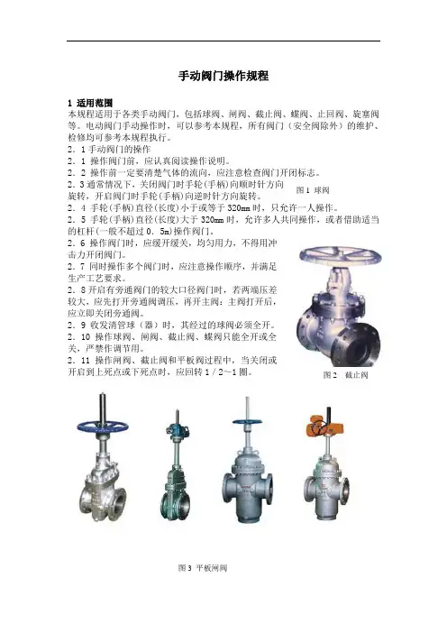
手动阀门操作规程1 适用范围本规程适用于各类手动阀门,包括球阀、闸阀、截止阀、蝶阀、止回阀、旋塞阀等。
电动阀门手动操作时,可以参考本规程,所有阀门(安全阀除外)的维护、检修均可参考本规程执行。
2.1手动阀门的操作2.1 操作阀门前,应认真阅读操作说明。
2.2 操作前一定要清楚气体的流向,应注意检查阀门开闭标志。
2.3通常情况下,关闭阀门时手轮(手柄)向顺时针方向旋转,开启阀门时手轮(手柄)向逆时针方向旋转。
2.4 手轮(手柄)直径(长度)小于或等于320mm 时,只允许一人操作。
2.5 手轮(手柄)直径(长度)大于320mm 时,允许多人共同操作,或者借助适当的杠杆(一般不超过0.5m)操作阀门。
2.6 操作阀门时,应缓开缓关,均匀用力,不得用冲击力开闭阀门。
2.7 同时操作多个阀门时,应注意操作顺序,并满足生产工艺要求。
2.8开启有旁通阀门的较大口径阀门时,若两端压差较大,应先打开旁通阀调压,再开主阀:主阀打开后,应立即关闭旁通阀。
2.9 收发清管球(器)时,其经过的球阀必须全开。
2.10 操作球阀、闸阀、截止阀、蝶阀只能全开或全关,严禁作调节用。
2.11 操作闸阀、截止阀和平板阀过程中,当关闭或开启到上死点或下死点时,应回转1/2~1圈。
图1 球阀 图2 截止阀图3 平板闸阀2 阀门的维护操作2.1 阀门的日常维护2.1.1 应保持阀体及附件的清洁,阀门开关指示牌、阀门编号牌必须保持清晰可见。
2.1.2 检查阀门的油杯、油嘴、阀杆螺纹和阀杆螺母及传动机构的润滑情况,及时加注合格润滑油、脂。
阀门加油时,应看清加油孔有没有胶塞封口,如果有应清除掉。
阀门加油前应把阀开关启闭一次,并复原,然后才加油,这样才能使开关活动时带进管道损耗掉的密封脂得以补充。
2.1.3 检查阀门填料压盖、加油孔、加油孔螺帽、放散球阀、放散球阀阀芯、丝堵、膨胀节、阀盖与阀体连接及阀门法兰等处有无渗漏。
同时应注意整个阀体的防腐情况。
Instruction Manual Two Hand Control Valve Series VR51The intended use of this product is a logic unit for use in two-hand controlcircuits according to ISO 13851 type IIIA. When properly integrated intoa suitable safety system VR51 is compatible for use in systems up toCategory 1 as defined by EN ISO 13849-1:2015.1 Safety InstructionsThese safety instructions are intended to prevent hazardous situationsand/or equipment damage. These instructions indicate the level ofpotential hazard with the labels of “Caution,” “Warning” or “Danger.”They are all important notes for safety and must be followed in additionto International Standards (ISO/IEC) *1), and other safety regulations.*1) ISO 4414: Pneumatic fluid power - General rules relating to systems.ISO 4413: Hydraulic fluid power - General rules relating to systems.IEC 60204-1: Safety of machinery - Electrical equipment of machines.(Part 1: General requirements)ISO 10218-1: Robots and robotic devices - Safety requirements forindustrial robots - Part 1: Robots.This manual contains essential information for the protection of users andothers from possible injury and/or equipment damage.•Refer to product catalogue, Operation Manual and HandlingPrecautions for SMC Products for additional information.•Read this manual before using the product, to ensure correct handling,and read the manuals of related apparatus before use.• Keep this manual in a safe place for future reference.•To ensure safety of personnel and equipment the safety instructions inthis manual must be observed, along with other relevant safetypractices.Caution Caution indicates a hazard with a low level of risk which, ifnot avoided, could result in minor or moderate injury.Warning Warning indicates a hazard with a medium level of riskwhich, if not avoided, could result in death or serious injury.Danger Danger indicates a hazard with a high level of risk which, ifnot avoided, will result in death or serious injury.Warning•The compatibility of the product is the responsibility of the personwho designs the equipment or decides its specifications.Since the product specified here is used under various operatingconditions, its compatibility with specific equipment must be decidedby the person who designs the equipment or decides its specificationsbased on necessary analysis and test results. The expectedperformance and safety assurance of the equipment will be theresponsibility of the person who has determined its compatibility withthe product. This person should also continuously review allspecifications of the product referring to its latest catalogue information,with a view to giving due consideration to any possibility of equipmentfailure when configuring the equipment.•Only personnel with appropriate training should operatemachinery and equipment.The product specified here may become unsafe if handled incorrectly.The assembly, operation and maintenance of machines or equipmentincluding our products must be performed by an operator who isappropriately trained and experienced.•Do not service or attempt to remove product and machinery/equipment until safety is confirmed.1) The inspection and maintenance of machinery/equipment shouldonly be performed after measures to prevent falling or runaway ofthe driven objects have been confirmed.1 Safety Instructions - continued2) When the product is to be removed, confirm the safety measures asmentioned above are implemented and the power from anyappropriate source is cut, and read and understand the specificproduct precautions of all relevant products carefully.3) Before machinery/equipment is restarted, take measures to preventunexpected operation and malfunction.•Do not use this product outside of the specifications.Contact SMC beforehand and take special consideration of safetymeasures if the product is to be used in any of the followingconditions.1) Conditions and environments outside of the given specifications oruse outdoors or in a place exposed to direct sunlight.2) Installation on equipment in conjunction with atomic energy,railways, air navigation, space, shipping, vehicles, military, medicaltreatment, combustions and recreation, or equipment in contact withfood or beverages, emergency stop circuits, clutch and brake circuitsin press applications, safety equipment or other applications unsuitablefor the specification described in this document.3) An application which could have negative effects on people,property or animals requiring special safety analysis outside the scopeof ISO 13851 described in this document.4) Use in an interlock circuit, which requires the provision of doubleinterlock for possible failure by using a mechanical protective function,and periodical checks to confirm proper operation.•Always ensure compliance with relevant safety laws andstandards.•All electrical work must be carried out in a safe manner by a qualifiedperson in compliance with applicable national regulations.Caution•The product is provided for use in manufacturing industries.The product herein described is basically provided for peaceful use inmanufacturing industries.•If considering using the product in other industries, consult SMCbeforehand and exchange specifications or a contract if necessary.If anything is unclear, contact your nearest sales branch.2 SpecificationsWarningSpecial products (-X) might have specifications different from thoseshown in this Instruction Manual. Contact SMC for specific drawings.2.1 Valve specificationsFluid AirOperating pressure [MPa] 0.25 to 1.0Proof pressure [MPa] 1.5Ambient and fluid temperature [°C] -5 to 60 (with no freezing)FlowcharacteristicsC[dm3/(s·bar)] b CvP(1+2) to A(2) 0.3 - -A(2) to R(4) 1.0 0.12 0.25Maximum operating frequency [cpm] 10Minimum operating frequency Once every 30 daysImpact / vibration resistance [m/s2] Note 1)1000 / 50Mounting orientation UnrestrictedAir quality 5 µm filtration or smallerEnvironment Indoor use onlyPort size Metric Ø6Inch Ø1/4Applicable tube material Note 2)Nylon, Soft nylon, Polyurethane,Flame resistant (FR) soft nylon,FR double layer,FR double layer polyurethaneWeight [g] 340AccessoryoptionSilencer Part No.: AN101-01Bracket Part No.: VR51BB10D[cycles] 1,000,000 Note 3)Mission time [years or cycles] Maximum 20 years or when thenumber of cycles = B10D, whicheveroccurs first Note 4)Table 1.Note 1) Impact resistance: No malfunction occurred when tested in the axialdirection and right angle to the valve.Vibration resistance: No malfunction occurred in a round sweep testbetween 10 to 150 Hz. The test was performed in the axial direction andright angles to the valve axis, 20 times for each condition.Note 2) In the case of soft nylon or polyurethane tubing, use caution when themaximum operating pressure of the tubing is used.Note 3) The B10D figure is estimated from SMC life test.2 Specifications - continuedNote 4)The period of intended use of the product shall not exceed the mission time(T M). The user is expected to calculate the product T10D according to ISO13849 based on the stated B10D and operating cycles (n op) of theapplication. The period of intended use of the product shall be the shorterof T M or T10D and neither is a guarantee of the actual life of the product.After the period of intended use has expired the product shall be replacedwith a new unit.2.2 Pneumatic symbolFigure 1.2.3 Typical circuitFigure 2.2.4 Circuit functional description / timing•When there is a time delay of less than 0.5 seconds between the twoair signal inputs, the VR51 provides an output signal.•VR51 output stops when one of the two air signal inputs stops.•Two simultaneous air signals reset the output.Figure 3. Output time delay2.5 Output timing delay•Example for typical piping, the exact delay will depend on the application.Figure 4. Output timing delay from supply pressure2 Specifications - continued2.6 Declaration of conformityFigure 5.Figure 6.Conditions1, Piping: Tube: T0604 with I.D. Ø4mm2, Piping length:Primary side 1mSecondary side 3m3, Connected equipment: 1 Air operatedvalveORIGINAL INSTRUCTIONSP1P2R(4)A(2)The output delaydepends on thepiping arrangementand the operatingpressure. Therelationship betweenoutput timing delayand pressure is givenin 2.5.Maximumoutputtimingdelay[s]Supply pressure [MPa]OutputNooutputOutput delayTwo hand control valve (VR51)Push buttonoperated valvePush buttonoperated valveAir operatedvalveCylinder2 Specifications - continuedFigure 7.2.7 Batch codeThe batch code indicated in the product label translates to constructionyear / month according to the following table (eg. BQ = Mar 2023):Construction Production batch codesYear / Month Jan Feb Mar Apr May Jun Jul Aug Sep Oct Nov Dec2023 Bo BP BQ BR BS BT BU BV BW BX By BZ2024 Co CP CQ CR CS CT CU CV CW CX Cy CZ…………………………………2026 Eo EP EQ ER ES ET EU EV EW EX Ey EZTable 2.3 Installation3.1 InstallationWarning•Do not install the product unless the safety instructions have been readand understood.•Do not install the product if it appears to have been damaged duringtransport.•Do not paint the product.•Do not remove or cover up warnings or specifications printed or affixedto the product.•Ensure sufficient space for maintenance activities. When installing theproducts, allow access for maintenance.•Ensure that the connections of pipework to the unit do not result in aresidual trip hazard to system operators or maintainers.•If air leakage increases or equipment does not operate to specification,stop operation.•Check mounting conditions when air supplies are connected. Initialfunction and leakage tests should be performed after installation.3.2 EnvironmentWarning•Do not use in an environment where corrosive gases, chemicals, saltwater or steam are present.3 Installation - continued•Do not use in an explosive atmosphere.•Do not expose to direct sunlight. Use a suitable protective cover.•Do not install in a location subject to vibration or impact in excess ofthe product’s specifications.•Do not mount in a location exposed to radiant heat that would result intemperatures in excess of the product’s specifications.•Employ suitable protective measures in locations where there iscontact with oil or welding spatter etc.•Ambient humidityWhen using the valve in environments with low humidity, takemeasures to prevent static.If the humidity rises, take measures to prevent the adhesion of waterdroplets on the valve.Do not use in high humidity environment where condensation occurs.•Altitude limitation is 1000 m above sea level.CautionAvoid using in places where there is splashing oil, coolant or water. Inaddition, avoid using where dust may adhere.3.3 PipingCaution•Before connecting piping make sure to clean up chips, cutting oil, dustetc.•When installing piping or fittings, ensure sealant material does notenter inside the port. When using seal tape, leave 1 thread exposedon the end of the pipe/fitting.•Tighten fittings to the specified tightening torque.•Connect tubing with a longer length than required to prevent torsion,stretching or moment loads. Damage of the fittings or flattening, aswell as bursting or releasing of the tubing may occur if the instructionsare not followed.•Tubing connected to the VR51 should be used at more than itsminimum bend radius. If used under the minimum bend radius,bending or flattening of the tubing may occur. Refer to catalogue foradditional information.3.3.1 Piping length for secondary sideTo help avoid output timing delay;•Use the same tubing length and diameter between the VR51 and eachcontrol actuating device: L1=L2, L1’=L2’.•Use the same control valve type for each input port: V1=V2•Operate the control valves with the same pressure: P1=P2Figure 8.3.4 LubricationCaution•SMC products have been lubricated for life at manufacture, and do notrequire lubrication in service.•If a lubricant is used in the system, use turbine oil Class 1 (no additive),ISO VG32. Once lubricant is used in the system, lubrication must becontinued because the original lubricant applied during manufacturingwill be washed away.3.5 Air supplyWarning•When there is a large amount of condensate.Compressed air containing a large amount of water vapour can causemalfunction of pneumatic equipment such as valves. An air dryer orwater separator should be installed upstream from filters.•Drain flushingIf condensation in the drain bowl is not emptied on a regular basis, thebowl will overflow and allow the condensation to enter the compressedair lines. It causes malfunction of pneumatic equipment.3 Installation - continuedIf the drain bowl is difficult to check and remove, installation of a drainbowl with an auto drain option is recommended.•Type of airDo not use compressed air that contains chemicals, synthetic oilsincluding organic solvents, salt or corrosive gases, etc., as it can causedamage or malfunction.Caution•When extremely dry air is used as the fluid, degradation of thelubrication properties inside the equipment may occur, resulting inreduced reliability (or reduced service life) of the equipment. Pleaseconsult with SMC.•Install an air filter upstream near the valve. Select an air filter with afiltration size of 5 μm or smaller.•Take measures to ensure air quality, such as by installing anaftercooler, air dryer, or water separator.•If excessive carbon powder is seen, install a mist separator on theupstream side of the valve.If excessive carbon dust is generated by the compressor it may adhereto the inside of a valve and cause it to malfunction.Warning•Minimise the distance between the valve and the air supply andbetween the valve and the protected system.•Do not place any devices between the valve and the protected systemthat might interfere with the safety function.•The exhaust ports of the valve should not be left unconnected.•The exhaust ports of the valves should never be blocked and must beprotected from ingress of contamination by a suitable silencer or devicewhich does not affect the valve function.3.6 Mounting•The valve can be mounted using 2 x M5 x 0.8 bolts (thread depth:5 mm) or using a bracket with 2 x ∅6.5 mm diameter holes. Tighteningtorque for M5 thread is 1.5 to 3 N∙m.•Refer to catalogue for more details.3.7 One-touch fittingsCautionRefer to catalogue for specific precautions.4 Settings4.1 Operating button setupCaution•Design and prepare the buttons in accordance with instructionmanuals. Install the buttons according to ISO 13851 Safety ofmachinery - Two-hand control devices - Functional aspects - Principlesfor design and other applicable standards.•If the operating buttons are incorrectly arranged, an unexpectedmotion is likely to occur and safety cannot be maintained.•Principle precautions (reference only):- Configure the buttons so only 2 hand operation is possible, ensureit is not possible to operate by 1 hand only.- Configure the buttons so only 2 hand operation is possible, ensureit is not possible to operate by forearm(s) or elbow(s).- Configure the buttons so only 2 hand operation is possible, ensureit is not possible to operate by 1 hand and any other part of thebody (knee or hip for example).•Example of button setup:- Ensure a safe spacing of the buttons so they cannot be operatedby 1 hand.Figure 9.- Install an isolating object between the buttons so they cannot beoperated by 1 hand.Figure 10.- Place a cover over both buttons so they cannot be operated by 1hand.4 Settings - continuedFigure 11.5 How to OrderRefer to catalogue for ‘How to Order’.6 Outline DimensionsRefer to catalogue for outline dimensions.7 Maintenance7.1 General maintenanceCaution•Not following proper maintenance procedures could cause the productto malfunction and lead to equipment damage.•If handled improperly, compressed air can be dangerous.•Maintenance of pneumatic systems should be performed only byqualified personnel.•Before performing maintenance, turn off the power supply and be sureto cut off the supply pressure. Confirm that the air is released toatmosphere.•After installation and maintenance, apply operating pressure andpower to the equipment and perform appropriate functional andleakage tests to make sure the equipment is installed correctly.•If any electrical connections are disturbed during maintenance, ensurethey are reconnected correctly and safety checks are carried out asrequired to ensure continued compliance with applicable nationalregulations.•Do not make any modification to the product.•Do not disassemble the product, unless required by installation ormaintenance instructions.7.2 Periodic testing•The product should be tested regularly for proper operation of thesafety functions.•Testing should be conducted at start-up and then at regular intervalsdetermined by the end user depending on complete systemrequirements. The test should consist of operation of the safety systemand observation of the following, replace product if necessary:- There are no scratches, dents, corrosion, loose screws, or damageto the valve body.- The one-touch fitting is not damaged.- The tube should not be kinked, crushed or damaged.- The tube should not be hardened, deteriorated or softened.- No air leaks.- The air pressure is in the range of 0.25 MPa to 1 MPa.- Operate the two operating devices installed on the ‘I nput’ side atthe same time and ensure that there is output from port A of VR51.- The operation timings of the two operating devices installed on the‘In put’ side are shifted by 0.5 seconds or more, and there is nooutput from port A of VR51.- When one of the operating devices is cancelled while there isoutput from port A of VR51, there is no output from port A.7.3 Maintainable partsWarningThere are no replaceable parts.8 Limitations of UseWarning•The system designer should determine the effect of the possible failuremodes of the product on the system.•VR51 only offers protection for the person operating it.8.1 Limited warranty and disclaimer/compliance requirementsRefer to Handling Precautions for SMC Products.8.2 Type of fluid and pneumatic pressure•Do not use fluids other than those specified. The only fluid that can beused is air.OutputSupply port: P1(11)Supply port: P2(12)Exhaust port R(4)Output port A(2)Flame resistant One-touch fitting: ∅6, ∅1/4Flame resistant One-touchfitting: ∅6, ∅1/4Flame resistant One-touchfitting: ∅6, ∅1/4With silencer(order separately,see Table 1.)P2P1V2V1• Do not use the product with a pressure under 0.25 MPa. The time lag for operating the VR51 is different depending on the operating pressure. The higher the operating pressure, the shorter the time lag, and vice versa. If used under 0.25 MPa, an output will be produced; however, safety is not likely to be maintained, even though the time lagmay exceed 0.5 seconds.Caution8.3 Low temperature operationIn the case of using in low temperature, take measures not to freeze thedrainage or moisture.Note: If there are doubts about the performance of the unit, replace the whole unit.8.5 LimitationsCaution• This product is CE/UKCA marked as a safety component as defined under the Machinery Directive 2006/42/EC / The Supply of Machinery (safety) Regulations 2008. For details, please refer to the Declaration of Conformity supplied with the product.• The valve may only be used to provide the stated safety function as a logic unit for use in two-hand control circuits. The valve can only perform as a safety component when properly installed in a system conforming to the appropriate safety standards. • Any such use must be within the specified limits and application conditions for the product.• In order to meet a required performance level as defined by the appropriate safety standard, the user must provide all the other necessary components to complete function of the safety system. • The user is responsible for the specification, design, implementation, validation and maintenance of the safety system.Warning10 Product DisposalThis product shall not be disposed of as municipal waste. Check your local regulations and guidelines to dispose this product correctly, in order to reduce the impact on human health and the environment.11 ContactsRefer to or www.smc.eu for your local distributor/importer.URL : https:// (Global) https:// www.smc.eu (Europe) SMC Corporation, 4-14-1, Sotokanda, Chiyoda-ku, Tokyo 101-0021, JapanSpecifications are subject to change without prior notice from the manufacturer. © 2023 SMC Corporation All Rights Reserved. Template DKP50047-F-085M。
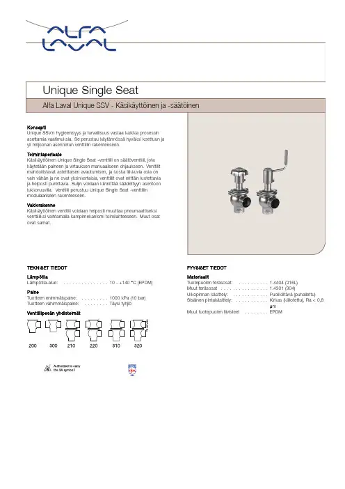
TEKNISET TIEDOT LämpötilaLämpötila-alue:...............10-+140°C (EPDM)PaineTuotteen enimmäispaine:.........1000kPa (10bar)Tuotteen vähimmäispaine:........Täysi tyhjiöVenttiilipesänyhdistelmätFYYSISET TIEDOT MateriaalitTuotepuolen teräsosat:..........1.4404(316L)Muut teräsosat ................1.4301(304)Ulkopinnan käsittely:............Puolikiiltävä(puhallettu)Sisäinen pintakäsittely:...........Kirkas (kiillotettu),Ra <0,8µmMuut tuotepuolen tiivisteet........EPDMLisävarusteetA.Kierreosat ja pantaliittimet vaaditun standardin mukaisesti.B.Tuotepuolen HNBR-tai FPM-tiivisteet.C.Karan HNBR-,FPM-tai TR2-tiiviste(kelluva PTFE-rakenne-vainkäsikäyttöinen venttiili).D.Kiiltäväulkopinta.HuomautusKatso lisätiedot ohjeesta ESE00307.Muita samaan perusrakenteeseen perustuvia venttiileitäVenttiilisarjassa on useita erikoisventtiilejä.Seuraavassaluettelossa on joitakin saatavilla olevista venttiilimalleista;tutustukaikkiin malleihin ja vaihtoehtoihin Alfa Lavalin tietokoneavusteisenvalintatyökalun(Anytime-mitoitusohjelma)avulla.-Vakioventtiili.-Vastasuuntaventtiili.-Aseptinen venttiili.-Pitkäiskuinen venttiili.-Säiliön pohjaventtiili.Toimilaitteella on viiden vuoden takuu.Mitat(mm)-Käsikäyttöiset Unique-venttiilitKoko25385163.576.1101.6DN DN DN DN DN DN mm mm mm mm mm mm2540506580100 A11245245259285291337247247260284295338 A21260265284310321367262267285309325368 A31291307332371390460297312336376402464 A41303324354393417487309329358398429491 C47.860.873.886.398.9123.652647692107126 OD25385163.576.1101.62941537085104 ID21.834.847.860.372.997.62638506681100 t 1.6 1.6 1.6 1.6 1.62 1.5 1.5 1.5222 E15049.56181861195049.5627887120 E25049.56181861195049.5627887120 F1152025253030152025253030 F2121722222727121722222727 H105105105105105105105105105105105105 M/ISO panta212121212121------M/DIN panta------212121282828 M/DIN kierreosa------222223252530 M/SMS kierreosa202020242435------Paino(kg)Sulkuventtiili 1.8 2.0 2.6 3.6 4.67.0 1.9 2.1 2.5 3.7 5.0 6.9 Vaihtoventtiili 2.6 3.0 4.2 5.67.311.4 2.8 3.2 4.2 5.98.211.21)Katso tarkat A1-A4-mitat Anytime-mitoitusohjelmantiedoista.TD 454-014Sulkuventtiili Vaihtoventtiili Karan PTFE-tiiviste(TR2) Kuva2.Mitat.Kv-arvotVenttiilin koko Kv38mm/DN4014*/4451mm/DN507563.5mm/DN6511376.1mm/DN80171101.6mm/DN100250*valinnainenKv=m3/h,kun painehäviöon1bar.Kun painehäviöon muuta kuin1bar,virtaus lasketaan seuraavalla kaavalla:Q=Kv x√∆pJossaQ=virtaus m3/h.Kv=ks.edellä.∆p=Painehäviöventtiilissä,bar.Esimerkki:Kara Kv75Q lasketaan∆p=2bar:Q=75x√2=106m3/htai50%iskulla:Q=0,5x75x√2=53m3/hPainehäviö-/kapasiteettikaaviotSuljinten ominaisuudet ovat lineaariset.Tämätarkoittaa,ettätiettymääräkuristamista iskua pienentämälläaiheuttaa verrannollisen virtauksen vähenemisen,jos tuotteen paine pysyymuuttumattomana. Kuva3.Virtaus,%kokonaisvirtauksesta,kun painehäviöon1bar.Mitat(mm)-Käsikäyttöiset Unique-venttiilitKoko385163.576.1101.6DN DN DN DN DNmm mm mm mm mm40506580100 A1176189215221267178191215226269 A2196214240251297198216240256299 OD385163.576.1101.641537085104 ID34.847.860.372.997.638506681100 t 1.6 1.6 1.6 1.62 1.5 1.5222 E149.561818611949.5627887120 E249.561818611949.5627887120 F120252530302025253030 H80808080808080808080 M/ISO panta2121212121-----M/DIN panta-----2121282828 M/DIN kierreosa-----2223252530 M/SMS kierreosa2020242435-----Paino(kg)-Sulkuventtiili 2.1 2.9 4.0 5.48.2 2.2 2.9 4.1 5.98.1Kuva4.MitatESE00276FI1507Tiedot vastaavat julkaisuhetken tietoja,oikeudet muutoksiin pidätetään.ALFA LAVAL on Alfa Laval Corporate AB:n rekisteröimäja omistamatuotemerkki.©Alfa LavalAlfa Lavalin yhteystiedotEri maiden ajan tasalla olevat yhteystiedotovat yhtiön verkkosivuilla.Tiedot on julkaistu osoitteessa .。
Hand lever valves VHERHand lever valves VHERKey featuresPowerful Versatile Practical-M-Flow rate170 ... 3800 l/min• 4/3-way valvemid-position closedmid-position exhaustedmid-position pressurised• Connections M5, G1/8, G1/4, G1/2• 3/3-way valveHand lever valves VHER can be usedas 3/3-way valves by sealing port 2With these valves it is possible to stopsingle-acting cylinders (3/3-way valve)or double-acting cylinders (4/3-wayvalve) within the stroke range.With mid-position closed, the drivepiston moves until the forces arebalanced.With mid-position exhausted the pis-ton can be moved manually; only thefrictional forces have to be overcome.With mid-position pressurised, thepressure at ports 2 and 4 is the same.The piston is not moved (in the case offlat surfaces).2d Internet: /catalogue/...Subject to change – 2023/08Hand lever valves VHER Product range overview – Metal lever3 2023/08 – Subject to change d Internet: /catalogue/...Hand lever valves VHERProduct range overview – Polymer lever4d Internet: /catalogue/...Subject to change – 2023/08Hand lever valves VHER Peripherals overviewControl panel installation – Metal lever71) For design reasons, it is not possible for every hand lever valve VHER to be screwed to a control panel on the lever side using mounting screws.5 2023/08 – Subject to change d Internet: /catalogue/...Hand lever valves VHERPeripherals overviewControl panel installation – Polymer lever71) For design reasons, it is not possible for every hand lever valve VHER to be screwed to a control panel on the lever side using mounting screws.6d Internet: /catalogue/...Subject to change – 2023/08-NoteH-For design reasons, it is not possible for every hand lever valve VHER to bescrewed to a control panel on the lever side using mounting screws.7 2023/08 – Subject to change d Internet: /catalogue/...Hand lever valves VHERType codes8d Internet: /catalogue/...Subject to change – 2023/08Hand lever valves VHER Data sheet – Version with metal lever-M-Flow rate600 ... 3800 l/min -L- Pressure–0.95 ... +10 bar -Q-Temperature range–20 ... +80°CG1/4G1/24/3-way, detenting, mid-position closed, exhausted or pressurisedOption of front panel mounting or through-holes1) Corrosion resistance class 2 to Festo standard 940070Components subject to moderate corrosion stress. External visible parts with primarily decorative surface requirements which are in direct contact with the surrounding industrial environment or media such as coolants or lubricatingagents.9 2023/08 – Subject to change d Internet: /catalogue/...Hand lever valves VHERData sheet – Version with metal lever Operation with different pressuresVacuum operationThe direction of flow of the VHER-B43 valves is clearly defined and cannot be reversed.Vacuum must only be connected toport 3 in order to maintain thedirection of flow.Vacuum operation at port 3:–0.95 ... 0 barH--NoteA filter must be installed upstream of valves operated in vacuum mode. This prevents any foreign matter in the intake air getting into the valve (e.g. when operating a suction cup with connector).During vacuum operation, the valvefunction changes from exhausted(VHER-...-B43E-...) to pressurised(VHER-...-B43U-...) and vice versa.H--NoteVacuum must not be connected toport 1.With vacuum operation: Mid-position closed (VHER-...-B43C-...)With vacuum operation:Mid-position pressurised(VHER-...-B43U-...)With vacuum operation:Mid-position exhausted(VHER-...-B43E-...)Connections with vacuum:• Vacuum is generated by connectingvacuum generator to port 3• Exhaust (or pressurisation) takesplace via port 1• Vacuum operation (e.g. suction cup)takes place at port 2 (or 4) (During normal operation: mid-positionclosed VHER-...-B43C-...)(During normal operation: mid-positionexhausted VHER-...-B43E-...)(During normal operation: mid-positionpressurised VHER-...-B43U-...)Dual-pressure operationValves VHER-B43 are suitable fordual-pressure operation.Please note that for design reasonscompressed air may only be applied toport 1 and 3.H--NoteIn the case of dual-pressure opera-tion, the higher pressure mustalways be applied to port 1.Mid-position closedVHER-...-B43C-...Mid-position exhaustedVHER-...-B43E-...Mid-position pressurisedVHER-...-B43U-...Connections with dual-pressureoperation:• Supply port: port 1 (high pressure)• Supply port: port 3 (lower pressure)10d Internet: /catalogue/...Subject to change – 2023/08Sectional viewHand lever valve VHER-H-B43-...Hand lever valve VHER-H-B43...-B-...Ordering data1) The hand lever valve can be used as a 3/3-way valve by sealing port 2.1) Packaging unit1) Packaging unit1) Packaging unit1) Packaging unit1) Packaging unit-M-Flow rate170 ... 3800 l/min-L- Pressure–0.95 ... +10 bar-Q-Temperature range–20 ... +80°C1) Corrosion resistance class 2 to Festo standard 940070Components subject to moderate corrosion stress. External visible parts with primarily decorative surface requirements which are in direct contact with the surrounding industrial environment or media such as coolants or lubricating agents.Operation with different pressures Vacuum operationThe direction of flow of the VHER-B43 valves is clearly defined and cannot be reversed.Vacuum must only be connected toport 3 in order to maintain thedirection of flow.Vacuum operation at port 3:–0.95 ... 0 barH--NoteA filter must be installed upstream of valves operated in vacuum mode. This prevents any foreign matter in the intake air getting into the valve (e.g. when operating a suction cup with connector).During vacuum operation, the valvefunction changes from exhausted(VHER-...-B43E-...) to pressurised(VHER-...-B43U-...) and vice versa.H--NoteVacuum must not be connected toport 1.With vacuum operation: Mid-position closed (VHER-...-B43C-...)With vacuum operation:Mid-position pressurised(VHER-...-B43U-...)With vacuum operation:Mid-position exhausted(VHER-...-B43E-...)Connections with vacuum:• Vacuum is generated by connectingvacuum generator to port 3• Exhaust (or pressurisation) takesplace via port 1• Vacuum operation (e.g. suction cup)takes place at port 2 (or 4) (During normal operation: mid-positionclosed VHER-...-B43C-...)(During normal operation: mid-positionexhausted VHER-...-B43E-...)(During normal operation: mid-positionpressurised VHER-...-B43U-...)Dual-pressure operationValves VHER-B43 are suitable fordual-pressure operation.Please note that for design reasonscompressed air may only be applied toport 1 and 3.H--NoteIn the case of dual-pressure opera-tion, the higher pressure mustalways be applied to port 1.Mid-position closedVHER-...-B43C-...Mid-position exhaustedVHER-...-B43E-...Mid-position pressurisedVHER-...-B43U-...Connections with dual-pressureoperation:• Supply port: port 1 (high pressure)• Supply port: port 3 (lower pressure)Sectional viewHand lever valves VHER-P-H-B43-...Hand lever valves VHER-P-H-B43...-B-...Hand lever valves VHER Data sheet – Version with polymer lever31 2023/08 – Subject to change d Internet: /catalogue/...Hand lever valves VHEROrdering data1) The hand lever valve can be used as a 3/3-way valve by sealing port 2.32d Internet: /catalogue/...Subject to change – 2023/08Hand lever valves VHER Accessories1) Packaging unit33 2023/08 – Subject to change d Internet: /catalogue/...Hand lever valves VHERAccessories1) Packaging unit1) Packaging unit1) Packaging unit34d Internet: /catalogue/...Subject to change – 2023/08Festo - Your Partner in AutomationConnect with us/socialmedia 1Festo Inc.2Festo Pneumatic 3Festo Corporation 4Regional Service Center 5300 Explorer DriveMississauga, ON L4W 5G4CanadaAv. Ceylán 3,Col. Tequesquináhuac 54020 Tlalnepantla, Estado de México1377 Motor Parkway Suite 310Islandia, NY 117497777 Columbia Road Mason, OH 45040Festo Customer Interaction CenterTel:187****3786Fax:187****3786Email:*****************************Multinational Contact Center 01 800 337 8669***********************Festo Customer Interaction Center180****3786180****3786*****************************S u b j e c t t o c h a n g e。
阀门执行器手动使用说明手轮机构与气动执行器配套使用,当气源信号出现故障,阀门无法开启、关闭,或固定在某一位置时,就必须通过手轮来完成。
1.阀门的开启方向,通常是逆时针表示打开,顺时针表示阀门关闭。
因此,开关阀门时要注意方向。
2.阀门上的手轮、手柄是按正常人力设计的,因此,在阀门使用上规定,不允许操作者借助杠杆和长扳手开启或关闭阀门。
3.当手轮全开后,应倒转少许,使螺纹之间严紧,以免松动损伤。
4.若手轮是做限位用的,应在预定位置,检修时可借助标尺和记号记住它们全开和全关位置,这样可以避免全开时顶撞死点。
5.阀门出厂时,不论气动执行器是正作用还是反作用,手轮都在开启状态,并都用锁母锁死,以免操作人员误操作把手轮关下去,阀门无法打开或达不到所需流量,造成不必要的事故和损失。
6.操作人员在用手轮操作前,先将手轮锁母松掉,再进行操作,操作完成后,如无特殊说明,一定要把手轮打开,并用锁母锁死。
电动执行器手动操作说明实物照片及标识IQ系列电动执行器手轮图1(现场图片(1)手动/自动手柄(2)手轮手动/自动手柄手轮操作步骤说明侧装手轮压下手动/自动手柄(1),使其处于手动位置。
旋转手轮(2)以挂上离合器, 时松开手柄,手柄将自动弹回初始位置,手轮将持啮合状态, 直到执行器被电动操作, 手轮将自动脱离,回到电机驱动状态。
如果需要,可用一个带6.5mm铁钩的挂锁将离合器锁定在任何状态。
手轮机构不可以作为限位机构使用。
阿卡8C系列手动操作说明示例实物照片及标识812型顶装手轮(1)手轮(2)定位销(3)导杆(4)丝母操作步骤说明顶装手轮812型的顶装手轮机构操作时拔起定位销钉(2)。
812型的顶装手轮机构主要有手轮(1),定位销(2)、丝母(4)及导杆组件(3)组成。
逆时针旋转手轮时,丝母带动导杆向上使阀门打开;顺时针旋转手轮时,丝母带动导杆向下使阀门关闭。
阀门正常使用时,故障关阀门,观察阀门标尺指示是否在全关位置,确定手轮在空挡位置,定位销完全回位。
MANUAL VALVES VS. AUTOMATIC FLOW LIMITING VALVESydronic system balancing is an important part of the HVAC industry. Without hydronic balancing, some coils in a system have too much flow and other coils don’t have enough flow; the building isn’t “balanced.” An unbalanced system can lead to excessive occupancy complaints as people are either too cold or too hot in the building.Many engineers focus on carefully selecting energy efficient boilers, chillers, and terminal units. However, without proper flow through these units, their efficiencies and heat transfer capabilities are altered. The problem is exacerbated as the pressures change in the building’s hydronic system, as changing pressures have a direct impact on flowrate. Q=Cv√∆P) While the industry accepts that pressure changes cause flow changes which then causes heat transfer changes, many engineers still accept manual balance valves because the INITIAL unit cost is less than automatic or pressure independent valves. But is initial cost all there is to consider? Automatic & Pressure Independent Valves -the cost effective option over Manual Balance ValvesThe procedure to manually balance a system is very labor intensive. The pressure drop across each valve is measured and a ball or plug is adjusted to bring the pressure drop to design pressure. Each time a valve in the system is adjusted, the flow through the other valves will change including those previously set because of the pressure change. Hence, the previously set valves must be reset, which in turn affects the flow through the other valves...and so on. In a large system, a minimum of three balances per valve is generally recommended by ASHRAE and NEBB.Contractor price for ¾” manual balance valve with memory stop: $35.Cost to balance three times total: 20-30 minutes @$125./hr: $42.00 to $62.50 On the other hand, each automatic flow limiting or pressure independent (PI) valve is self balancing as soon as the pump is turned on. The only labor required is for flow verification. The pressure drop across each valve is measured by using the ports provided on the valve body. As long as the PSID is within the control range listed on the valve tag, the flow, which is also listed on the tag, will be within plus/minus 5%.HContractor price for 3/4” automatic valve with isolation valve: $60.Cost to verify flow: <5 min @ $125./hr: <$10.Manual = $77 to $97.5Automatic = <$70It is true the initial cost of a manual valve is less expensive than an automatic valve, but once labor to balance the valve is taken into consideration the total cost can be considerably more. More importantly, once the system is live and pressures start changing an automatic or PI valve will maintain the design flow in spite of system pressure changes. A manual valve will have an increase or decrease in flow as the pressure increases or decreases.Buy Fewer ValvesSystems utilizing automatic flow limiting or PI valves require far fewer balancing valves than systems that are manually balanced. Figure 1 shows a schematic of a system serving 18 heat transfer (heating or cooling) coils.Figure 1.The manual system, shown above, requires a total of 27 valves whereas the automatic system, on the right, requires only 18 because it does not require the “partner balancing valves” (shown in red) on the risers and the branches.As each terminal unit automatic flow limiting and pressure independent control valve isself-balancing over a wide differential pressure control range, the flow through the risers and the branches is also automatically controlled (balanced) without the use of additional valves.Using 18 valves instead of 27 manual valves is approximately 1/3 savings in initial product purchases. In our previous example that is 27*$77 to $97.5 or $2,079 to $2,632.50 in manual valve costs. In comparison the automatic system costs 18*$70 or $1,260 in valve costs which is a substantial savings.The elimination of the manual partner balancing valves on the mains, risers and branches in turn eliminates the head loss through them. Hence, the system head loss is reduced which lowers the pump head requirements.System Stays Balanced Even During Reduced Load ConditionsNo coil will starve when saving money by variable speed pumping. However, reducing the total water flow does not mean that all the coils in the building individually need the same reduction in flow. For example, on a typical spring day at 1:00 p.m., the total chilled water requirements of an8-story office building will generally be much less than on a hot summer (design) day. However, the air-handler serving the filled-to-capacity cafeteria, on the first floor, will require almost 100% (of design) chilled water. A building with automatic flow limiting or pressure independent valves will give you this diversity whereas one with manual balancing valves cannot.Figure 2.The schematic at the top shows the design load condition. The system operation point, at design load, is at (say) 125 feet of pump head. The head loss across the various elements (which adds up to 125 feet) for the cafeteria circuit, is as shown. Since the cafeteria is on the first floor, the head loss through the risers is negligible and is ignored.Please note, for design flow at design head, the head loss through the manual balancing valve is the same as that through an automatic flow control valve (86 feet).If this is a manually balanced building, as shown in Figure 3 on the left side, valve MBV #5 would have to be added and manually set. Howev-er, doing this would change the flows through existing valves MBV #1 through MBV #4 and they would also have to be reset. Similarly, upstream branch/riser balancing valves (not shown) may also have to be reset. The resulting labor cost can be significant.If this is a building with automatic flow control valves, as shown in Figure 3 on the right side, you would only have to add valve AFLV #4. Because these valves have wide control ranges, they would all automatically self balance to provide the required flows. No labor would be required to set the new valve or to reset any of the existing valves.Figure 3.The schematic in the middle shows what happens when system flow is reduced (by lowering the pump speed to 52%), if the system is manually balanced. At the lower speed, the pump head will be smaller as will all the pressure losses. Since nothing else has changed in the cafeteria coil circuit, the head loss through the various elements will decrease proportionately and now add up to 65 feet instead of 125. Since the head loss through the manual flow control valve is reduced to 44.7 feet and since flow is proportional to the square root of the head loss, the flow through the manual balancing valve (and the coil) is reduced to 72% (square root of 44.7/86). There is NOW a flow deficit of 28%.The schematic at the bottom shows what happens when system flow is reduced by the same amount if the system has automatic flow limiting valves. Again, the pump head decreases to 65 feet. However, the head loss distribution is not proportional. Instead, the cartridge inside the automatic flow control valve moves by a precise amount, to absorb only 26 feet of head and keeps the flow at the required 100%.With the automatic flow limiting or pressure independent valve, there is no flow deficit at reduced system flow and reduced pump head.(Note: In all three schematics of Figure 2, all losses in the pump room are ignored for clarity of discussion.)Building Renovation Does Not Require Hydronic System Rebalance Very often, space renovation in an existing building also changes the heating/cooling requirements of that space. For example, an open office area that is converted into a large conference room will require more cooling due to the additional sensible and latent heat from the people. This may result in an additional fan-coil unit for the conference room. Figure 3 illustrates this scenario for a Manual vs. Automatic system.Griswold Controls designed the first balance valve in the market in 1960, years before the first manual balance valve was designed and manufactured. The all stainless steel flow limiting cartridge is a standard in the industry because of its simply elegant design. Above its control range (blue colored area in Figure 4), the cup will move all the way in, exposing the minimum orifice area. In both cases, the cartridge will now act as a fixed orifice device, varying flow based on the out-of-range differential pressure.You do not have to worry about the cartridge ever shutting off the flow completely because a minimum orifice area is always open.C U P P A R T I A L L Y O U TCU P F UL L Y I N C U P F U L L Y O U T Below the control range, the cartridge acts as a variable flow device, allowing flow to vary below the rated amount.Above the control range, the cartridge acts as a variable control device, allowing flow to vary above the rated amount.Within the wide control range, the cartridge modulates in response to pressure differential changes to maintain a fixed flow rate within ±5% accuracy. Figure 4.2803 Barranca Parkway Irvine CA 92606 • Toll Free: 800.838.0858 • 1/18F-5586How does an Automatic Flow Limiting Valve Maintain Design Flow?When the differential pressure across the cartridge falls below its control range (pink colored area in Figure 4), the cup will come all the way out, exposing the maximum orifice area. Similarly, if the differential pressure across the cartridge rises。
手压阀的说明书
手压阀主要包括调节螺母、胶垫、阀体、弹簧、阀杆、锁紧螺母、销钉、手柄、球头和填料。
其中阀杆的锥面制造和阀体的锥面配合起密封作用,故这两个零件的最为重要。
手压阀工作原理是:电磁脉冲阀由电磁先导头、膜片和阀上海华宇物流体组成,膜片后腔的面积大于前腔的面积,气压作用力大,使膜片处在关闭位置,电控仪输入电信号,使电磁先导头吸合动柱,打开卸荷孔,膜片后腔的压力气体迅速排出,膜片前腔的压力气体将膜片抬起,打开脉冲阀通道进行喷吹,电信号消失,电磁先导头的弹簧使动柱签证立即复位封闭卸荷孔,膜片后腔气体压力和弹簧作用力使膜片关闭通道,阀停止喷吹,膜片上的阻尼孔,当先导头动柱抬起,气体压力卸荷时,起到阻加拿大投资移民尼气流的作用,当卸荷封闭时,使压力气体迅速充满到后腔,使膜片关闭通道,停止喷吹。
S P E C I A L S E R V I C E P I L O TFeatures• Ideal for valve automation for the oil and gas market • Reliable, robust design with high flow performance • Low temperature options• Stainless steel constructions are NACE MR0175- 2003 compliant• Corrosion resistant - 316L Stainless Steel valve materials make it ideal for offshore and harsh environments • Extensive manual and pneumatic options• Rated for air, inert gas, and sweet dry natural gas • SIL 3 Capable optionsConstructionApprovalsSIL 3 Capable optionsRefer to Engineering for details.Minimum Ambient/Fluid TemperatureImportantThese solenoid valves are intended for use on clean dry air, inert gas, or sweet dry natural gas filtered to 40 micron or better. The dew point of the media should be at least 10˚C (18˚F) below the minimum temperature to which any portion of the air, inert gas or sweet dry natural gas system could be exposed to prevent freezing.If lubricated air is used, the lubricants must be compatible with FKM and LT NBR elastomers. Instrument air in compliance with ANSI/ISA Standard 7.0.01-1996 exceeds the above requirements and is, therefore, an acceptable media for these valves.3 = Low Temperature NBRHow to orderBrass Stainless Steel FKM: -4˚F (-20˚C) -4˚F (-20˚C)NBR: -40˚F (-40˚C) -40˚F (-40˚C)Note:Low Temperature option for all manual component options: -20˚F to 200˚F (-29˚C to 93˚C)2Visit our website at /ASCO or contact us at (800) 972-2726Specifications English (Metric)3/4" and 1" valves can be used as selectors with LTNBR versions limited to -31˚F (-35˚C). In a selector valve, one pressure is applied to Port 1 and another pressure applied to Port 3. Operating the valve allows the user to select which input pressure will flow through Port 2. Port 2 will always be pressurized. Consult I&M sheet for more information.青岛秉诚自动化设备有限公司 服务热线:4006-918-365 传真:(86-532)585-10-365Specifications English (Metric)¡ 1/4", 3/8", and 1/2" brass and stainless steel valves can be used as selector valves with two different input pressures with no change to existing ratings.3/4" and 1" valves can be used as selectors with LTNBR versions limited to -31˚F (-35˚C). In a selector valve, one pressure is applied to Port 1 and another pressure applied to Port 3. Operating the valve allows the user to select which input pressure will flow through Port 2. Port 2 will always be pressurized. Consult I&M sheet for more information.Dimensions: inches (mm)Const. Ref. 2NC EXTERNAL PILOTConst Ref. 1NC EXTERNAL PILOT Note:For Normally Open constructions the operator and return end cap are switched with respect to ports 1 & 3.Note:For Normally Open constructions the operator and return end cap are switched with respect to ports 1 & 3.青岛秉诚自动化设备有限公司服务热线:4006-918-365 传真:(86-532)585-10-3654Visit our website at /ASCO or contact us at (800) 972-2726S P E C I A L S E R V I C E P I L O TConst. Ref. 3Dimensions: inches (mm)NC EXTERNAL PILOTConst. Ref. 4NC EXTERNAL PILOTNote:For Normally Open constructions the operator and return end cap are switched with respect to ports 1 & 3.Note:For Normally Open constructions the operator and return end cap are switched with respect to ports 1 & 3.Dimensions: inches (mm)Const. Ref. 5NC EXTERNAL PILOTNote:For Normally Open constructions the operator and return end cap are switched with respect to ports 1 & 3.Const. Ref. 6NC EXTERNAL PILOTNote:For Normally Open constructions the operator and return end cap are switched with respect to ports 1 & 3.青岛秉诚自动化设备有限公司服务热线:4006-918-365 传真:(86-532)585-10-3656Visit our website at /ASCO or contact us at (800) 972-2726S P E C I A L S E R V I C E P I L O TDimensions: inches (mm)Const. Ref. 7NC EXTERNAL PILOTNote:For Normally Open constructions the operator and return end cap are switched with respect to ports 1 & 3.Const. Ref. 8NC EXTERNAL PILOTNO EXTERNAL PILOTUNIVERSAL312Dimensions: inches (mm)Const. Ref. 93 PLACESConst. Ref. 10青岛秉诚自动化设备有限公司服务热线:4006-918-365 传真:(86-532)585-10-3658Visit our website at /ASCO or contact us at (800) 972-2726S P E C I A L S E R V I C E P I L O TDimensions: inches (mm)Const. Ref. 12Const. Ref. 11Dimensions: inches (mm)Const. Ref. 13EXTERNAL PILOTConst. Ref. 143 PLACES青岛秉诚自动化设备有限公司服务热线:4006-918-365 传真:(86-532)585-10-36510Visit our website at /ASCO or contact us at (800) 972-2726S P E C I A L S E R V I C E P I L O TDimensions: inches (mm)Const. Ref. 163 PLACESConst. Ref. 15EXTERNAL PILOT12Visit our website at /ASCO or contact us at (800) 972-2726Dimensions: inches (mm)Const. Ref. 17NO EXTERNAL PILOTNC EXTERNAL PILOTConst. Ref. 18青岛秉诚自动化设备有限公司 服务热线:4006-918-365 传真:(86-532)585-10-365S P E C I A L S E R V I C E P I L O TDimensions: inches (mm)Const. Ref. 19Const. Ref. 20NC EXTERNAL PILOTNO EXTERNAL PILOT14Visit our website at /ASCO or contact us at (800) 972-2726Dimensions: inches (mm)Const. Ref. 21NO EXTERNAL PILOTNC EXTERNAL PILOTConst. Ref. 22青岛秉诚自动化设备有限公司 服务热线:4006-918-365 传真:(86-532)585-10-365S P E C I A L S E R V I C E P I L O TDimensions: inches (mm)Const. Ref. 24Const. Ref. 23NC EXTERNAL PILOTNO EXTERNAL PILOTDimensions: inches (mm)Const. Ref. 25[Const. Ref. 26青岛秉诚自动化设备有限公司服务热线:4006-918-365 传真:(86-532)585-10-36516Visit our website at /ASCO or contact us at (800) 972-2726S P E C I A L S E R V I C E P I L O TDimensions: inches (mm)Const. Ref. 27Const. Ref. 283 PLACESBALL KNOB NOT SHOWN IN THIS VIEW18Visit our website at /ASCO or contact us at (800) 972-2726Dimensions: inches (mm)Const. Ref. 29HOLE3 PLACESConst. Ref. 30BALL KNOB NOT SHOWN IN THIS VIEW青岛秉诚自动化设备有限公司 服务热线:4006-918-365 传真:(86-532)585-10-365S P E C I A L S E R V I C E P I L O TDimensions: inches (mm)Const. Ref. 32NC EXTERNAL PILOTNO EXTERNAL PILOTUNIVERSAL312Const. Ref. 31NC EXTERNAL PILOT20Visit our website at /ASCO or contact us at (800) 972-2726Dimensions: inches (mm)Const. Ref. 33Const. Ref. 34青岛秉诚自动化设备有限公司 服务热线:4006-918-365 传真:(86-532)585-10-365。
机制课程设计说明书题目:手压阀院(部):机电工程学院专业:机电工程及自动化班级:机械XX姓名:XXX学号:XXXXXXXXX指导教师:XXXXXXX完成日期:2010年7月7日目录1 任务·12 典型零件AutoCAD图纸2.1主视图··22.2俯视图·22.3 左视图·23典型零件造型设计·34其他零件设计4.1 轴·74.2 托架·84.3 垫片·84.4 填料压盖·95装配效果图·96 CAXA制造工程师6.1 加工对象的加工造型·106.2生成刀具轨迹·106.3知识加工轨迹明细单·12谢辞·13参考文献·13附录·141 任务了解手压阀的相关原理、组成,并查找相关资料,设计相应的零部件结构或机构,实现手压阀的基本功能要求。
(一)手压阀装配的手工绘图、以及塞座、阀体等二维图设计和手工绘制图。
选择典型零件进行工艺分析,编写机械加工工艺过程卡片,用CAXA 制造工程师进行造型设计,并生成刀具轨迹及加工仿真。
(二)对手压阀塞座和阀体的造型设计进行创新及改进,在造型设计中,要求使用尽可能少的命令来达到最佳的设计效果,设计的零件占用的计算机内存尽可能的少。
在装配过程中,选择最佳的装配过程及步骤,以满足手压阀的基本功能要求,并进行三维实体的渲染、零件的干涉检查等,具体时间安排详见任务书。
本课程设计在机械设计课程设计基础之上运用Solid Edge三维造型、CAXA制造工程软件对所设计的手压阀进行三维建模,并通过CAXA制造工程师进行进行造型设计,并生成刀具轨迹及加工仿真。
意义重大,机会难得,故需好好把握!2典型零件AutoCAD图纸2.1 主视图2.2 俯视图2.3 左视图3典型零件造型设计塞座零件设计1 首先打开Solid EdgeV16程序并点击草图,然后选择X-Y平面,在建模窗口中绘制正六边形,图形如下:2点击完成草图。
目录目录 (1)一数据分析 (2)二实体建模 (2)三运动分析 (5)(1)装备 (5)(2)分析 (9)(3)运动 (10)(4)受力分析 (13)四CAM加工 (15)(1)箱底底座加工 (15)(2)G代码 (18)五附件 (23)(1)工程图 (23)手压阀说明书一、数据分析1、图纸介绍:根据手压阀的轴侧图和零件图在A3纸上按1:1绘制装备图。
2、参数选择:开口销GB\T91-2000 4x18 公称直径d=4mm 长度l=50mm 材料Q235 不经表面处理螺纹:螺套M24 螺距p=2mm 中径D1=22.701mm 小径D2=21.835mm; 阀体M36螺距p=2mm中径D1=34.701mm 小径D2=33.835mm其他参数,详情见附件。
二、实体建模1球头:主要采用旋转等指令2垫片主要采用旋转等指令3螺套主要采用拉伸旋转等指令4销钉主要采用拉伸钻孔等指令5、箱座主要采用拉伸、旋转、伸出项(切口)等指令6、箱体主要采用拉伸、旋转、钻孔等指令7手柄主要采用拉伸旋转等指令三、机构运动分析1装备一、箱体装备:采用缺省约束二、手柄装备:采用销钉约束三、阀杆装备:采用圆柱和添加集轴承链接四、螺套装备:采用销钉连接五、销钉装备:采用缺省装备六、胶垫装备:采用缺省装备七、箱座装备:采用销钉和平面装备八、球头装备:采用缺省装备2分析一、伺服电动机二、弹簧系统三、阻尼3运动手压阀是吸气和排出液体的一种手动阀门。
当手握住手柄向下压紧阀杆时,阀杆压缩弹簧向下移动,入口开通,此时液体排出;当手柄抬起时,弹簧松开,阀杆向上贴紧阀体,液体则不能通过。
4、受力分析四、CAM加工(箱体底座加工)1创建毛坯2加工机床设置3车轮廓(区域车削)4车轮廓(轮廓车削)5车轮廓(车螺纹)6车轮廓(孔加工)7 G代码1>PARTNO / MFG00022>MACHIN/,122>PPRINT / MFG00021 Pro/NC-GPOST Mill UNCX01 6.3.WN00 P-20.0 MACHIN/UNCX01,12 DATE: 12/13/2013 PAGE 1NIIGATA HN50A - FANUC 15MA - B TABLE/ MFG0002 ( MM ) INPUT CLREC N5G2X43Y43Z43B33Q43R43I43J43K43F42D2S4T3M2H22 2 $ / MFG00022 2 N5 G71$2 2 N10 ( / MFG0002)$2>INSERT G0 G17 G99$2 2 N15 G0 G17 G99$2>INSERT G90 G94$2 2 N20 G90 G94$8>UNITS/MM9>TURRET/110>CAMERA/1,0,0,0,0,1,0,0,0,0,1,011>SPINDL/RPM,300,CLW11 11 N25 S300 M03$12>RAPID13>GOTO /34.2,0,4.54624113 13 N30 G0 Z4.546$13 13 N35 X34.2 Y0.$14>FEDRAT/200,MMPM15>GOTO /30,0,4.54624115 15 N40 G1 X30. F200.$16>GOTO /30,0,-3616 16 N45 Z-36.$17>GOTO /32.2,0,-3617 17 N50 X32.2$18>RAPID19>GOTO /32.2,0,4.54624119 19 N55 G0 Z4.546$20>FEDRAT/200,MMPM21>GOTO /28,0,4.54624121 21 N60 G1 X28. F200.$22>GOTO /28,0,-1422 22 N65 Z-14.$24>ARCDAT/28,0,-16,0,1,0,225>GOTO /30,0,-1625 25 N70 X28.126 Z-14.004$25 25 N75 X28.252 Z-14.016$25 25 N80 X28.377 Z-14.036$25 25 N85 X28.501 Z-14.064$25 25 N90 X28.622 Z-14.099$25 25 N95 X28.741 Z-14.142$25 25 N100 X28.857 Z-14.193$25 25 N105 X28.969 Z-14.251$25 25 N110 X29.078 Z-14.315$25 25 N115 X29.182 Z-14.387$25 25 N120 X29.282 Z-14.465$25 25 N125 X29.376 Z-14.549$ 125 25 N130 X29.465 Z-14.639$25 25 N135 X29.548 Z-14.734$25 25 N140 X29.625 Z-14.835$25 25 N145 X29.696 Z-14.94$25 25 N150 X29.759 Z-15.049$25 25 N155 X29.816 Z-15.162$25 25 N160 X29.865 Z-15.278$25 25 N165 X29.907 Z-15.398$25 25 N170 X29.941 Z-15.52$25 25 N175 X29.968 Z-15.643$25 25 N180 X29.987 Z-15.768$25 25 N185 X29.997 Z-15.894$25 25 N190 X30. Z-16.$26>GOTO /32.2,0,-1626 26 N195 X32.2$27>RAPID28>GOTO /32.2,0,4.54624128 28 N200 G0 Z4.546$29>FEDRAT/200,MMPM30>GOTO /26,0,4.54624130 30 N205 G1 X26. F200.$31>GOTO /26,0,-1431 31 N210 Z-14.$32>GOTO /30.2,0,-1432 32 N215 X30.2$33>RAPID34>GOTO /30.2,0,4.54624134 34 N220 G0 Z4.546$35>FEDRAT/200,MMPM36>GOTO /24,0,4.54624136 36 N225 G1 X24. F200.$37>GOTO /24,0,-1437 37 N230 Z-14.$38>GOTO /28.2,0,-1438 38 N235 X28.2$39>RAPID40>GOTO /28.2,0,4.54624140 40 N240 G0 Z4.546$41>FEDRAT/200,MMPM42>GOTO /22,0,4.54624142 42 N245 G1 X22. F200.$43>GOTO /22,0,-1443 43 N250 Z-14.$44>GOTO /26.2,0,-1444 44 N255 X26.2$45>RAPID46>GOTO /26.2,0,4.54624146 46 N260 G0 Z4.546$47>FEDRAT/200,MMPM148>GOTO /20,0,4.54624148 48 N265 G1 X20. F200.$49>GOTO /20,0,-1449 49 N270 Z-14.$50>GOTO /32.2,0,-1450 50 N275 X32.2$53>CAMERA/1,0,0,0,0,1,0,0,0,0,1,054>SPINDL/RPM,500,CLW54 54 N280 S500$55>RAPID56>GOTO /19.5,0,056 56 N285 G0 Z0.$56 56 N290 X19.5$57>FEDRAT/300,MMPM58>GOTO /19.5,0,-14.558 58 N295 G1 Z-14.5 F300.$59>GOTO /28,0,-14.559 59 N300 X28.$61>ARCDAT/28,0,-16,0,1,0,1.562>GOTO /29.5,0,-1662 62 N305 X28.109 Z-14.504$ 62 62 N310 X28.218 Z-14.516$ 62 62 N315 X28.326 Z-14.536$ 62 62 N320 X28.432 Z-14.564$ 62 62 N325 X28.536 Z-14.599$ 62 62 N330 X28.636 Z-14.642$ 62 62 N335 X28.734 Z-14.692$ 62 62 N340 X28.827 Z-14.749$ 62 62 N345 X28.916 Z-14.813$ 62 62 N350 X29.001 Z-14.883$ 62 62 N355 X29.08 Z-14.959$ 62 62 N360 X29.153 Z-15.04$ 62 62 N365 X29.22 Z-15.127$ 62 62 N370 X29.28 Z-15.218$ 62 62 N375 X29.334 Z-15.314$ 62 62 N380 X29.38 Z-15.413$ 62 62 N385 X29.419 Z-15.515$ 62 62 N390 X29.451 Z-15.62$ 62 62 N395 X29.475 Z-15.727$ 62 62 N400 X29.491 Z-15.835$ 62 62 N405 X29.499 Z-15.944$62 62 N410 X29.5 Z-16.$63>GOTO /29.5,0,-3663 63 N415 Z-36.$66>TURRET/267>CAMERA/1,0,0,0,0,1,0,0,0,0,1,068>SPINDL/RPM,100,CLW68 68 N420 S100$69>RAPID170>GOTO /23,0,070 70 N425 G0 Z0.$70 70 N430 X23.$71>FEDRAT/200,MMPM72>OP/THREAD,TURN,FEDTO,.306715,TPI,2,CUTS,3,FINCUT,1,CUTANG,18073>GOTO /18,0,073 73 N435 G1 X18. F200.$74>GOTO /18,0,-12.24714974 74 N440 Z-12.247$75>OP/THREAD,NOMORE76>RAPID77>GOTO /23,0,077 77 N445 G0 Z0.$77 77 N450 X23.$78>SPINDL/OFF81>TURRET/483>CAMERA/1,0,0,0,0,1,0,0,0,0,1,084>SPINDL/RPM,400,CLW84 84 N455 S400$85>RAPID86>GOTO /0,0,1086 86 N460 Z10.$86 86 N465 X0.$87>CYCLE/DRILL,FEDTO,12,MMPM,25,CLEAR,588>GOTO /0,0,088 88 N470 G81 X0. Y0. Z-12. R5. F25.$89>CYCLE/OFF89 89 N475 G80$90>RAPID91>GOTO /0,0,1091 91 N480 G0 Z10.$92>SPINDL/OFF94>AUXFUN/3094 94 N485 M30$94>FINI9494 %$五、附件(工程图)。