MUNTERS除雾器说明书(中文版)
- 格式:pdf
- 大小:451.88 KB
- 文档页数:29
2×660MW燃煤机组烟气脱硫总承包工程吸收塔除雾器安装作业指导书批准:审核:编制:目录1、工程概况 (3)2、编制依据 (3)3、施工组织计划 (4)4、施工前准备 (5)5、安装程序及工艺要求 (6)6、质量控制和验收标准............................ . (9)7、安全文明施工 (14)1、工程概况1.1 工程概述北面和东面为杭宁高速公路、104国道和铁路宣杭线,东临吕山港支流,南临吕山港,西侧紧靠乡级公路,西北侧为乌龟山。
厂址位于铁路宣杭线和吕由港之间场地上。
场地西北面乌龟山脚下为坐山湾村,与厂址场地相隔一条乡级公路;场地西面为高家庄,距离厂址约250m,吕山港南岸的杨吴村,距离厂址约350m,场地东面的施家门村,距离厂址约670m。
工程规模和性质:2×660MW燃煤机组烟气脱硫安装工程。
1.2 主要工程量1.2.1吸收塔主要参数:筒体φ16200/φ18200mm。
1.2.2吸收塔塔内件安装主要工作量2、编制依据2.1《吸收塔制作安装图》 T392S-J03062.2 MUNTERS除雾器安装图纸和安装使用说明书2.3 除雾器技术协议2.4《火电厂烟气脱硫工程施工质量验收及评定规程》 DL/T 5417-20092.5《吸收塔制造技术规范》 GH-FGD011S-RQ00012.6《火力发电厂焊接技术规程》DL/T869 20122.7《电力建设安全工作规程第1部分:火力发电厂》(DL5009.1—2002)2.8《建筑施工高处作业安全技术规范》JGJ80-912.9《施工组织总设计》2.10《火电施工质量检验及评定标准》(加工配制篇)19942.11《钢结构工程施工质量验收规范》 GB50205-20012.12 《电力建设安全健康与环境管理工作规定》20023、施工组织计划3.1施工进度安排单台吸收塔的除雾器安装正常工期为7个工作日。
安排如下:第一天:吊装及安装平台铺设检查;下层冲洗管道及喷嘴预装;下层除雾器部件清理、编号和归类;下层除雾器板吊装,开始塔内组装。
除雾器操作规程除雾器操作规程一、前言除雾器是一种常见的设备,用于去除汽车或其他机械设备上的雾气,提高视线,确保行车安全。
为了正确、安全地操作除雾器,制定了以下操作规程。
二、操作准备1. 准备工具和材料:除雾器、清洁布、清洁剂。
2. 检查设备:确保除雾器正常工作,无损坏或故障。
3. 清洁工作环境:确保操作环境干净整洁,没有杂物。
三、操作步骤1. 打开电源:将除雾器连接到电源,并确保电源开关处于关闭状态。
2. 准备清洁剂:根据使用说明,选择适合的清洁剂,并按照要求配置。
3. 清洁除雾器表面:用清洁布蘸取适量的清洁剂,轻轻擦拭除雾器外表面,确保表面干净无尘。
4. 清洁除雾器内部:打开除雾器的盖子,检查内部是否有灰尘或污垢。
如有,则使用清洁布轻轻擦拭,确保内部干净。
5. 安装除雾器:将除雾器安装到需要除雾的设备上,并确保安装牢固、稳定。
6. 调整除雾器角度:根据需要,调整除雾器的角度,确保除雾范围覆盖所需区域。
7. 打开电源开关:将电源开关打开,除雾器即开始工作。
8. 观察效果:观察除雾器的工作效果,如果视线已经明亮清晰,则可以停止操作;如仍存在问题,则需要进一步调整除雾器或处理其他原因。
9. 关闭电源开关:当不再需要使用除雾器时,将电源开关关闭。
10. 拆卸除雾器:按照安装步骤的逆序,将除雾器从设备上拆卸下来。
11. 清洁除雾器:再次用清洁布擦拭除雾器,确保表面和内部干净无尘。
12. 存储除雾器:将除雾器放置在干燥通风的地方,防止污染和损坏。
四、安全注意事项1. 操作人员必须熟悉除雾器的使用说明和操作规程,以避免操作错误导致事故发生。
2. 在操作除雾器时,应保持注意力集中,避免分心和粗心大意。
3. 在清洁除雾器时,应使用适量的清洁剂,避免使用过量或未经稀释的清洁剂。
4. 在清洁除雾器时,应使用柔软的清洁布,避免使用有损伤或硬性的物体,以免损坏除雾器表面。
5. 在安装和拆卸除雾器时,应防止设备倒塌或滑落,以免造成人身伤害。
除雾器安装
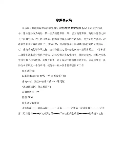
张热项目脱硫吸收塔内的除雾器采用MUNTERS EUROFORM GmbH公司生产的设备,除除雾器分为两层,第一层为粗除雾器,第二层为精除雾器。
两层除雾器之间有一定的空间。
为了防止堵塞,除雾器设置高效的冲洗系统,包含3层冲洗层,冲洗系统能够有效清除叶片上的沉淀物,保证除雾器不被堵塞和长时间的无故障运行。
冲洗系统能够在线运行,自动依据给定程序分别在第一级除雾器上、下游和第二级除雾器上游分别进行冲洗,冲洗喷嘴为实心锥喷嘴,能防止堵塞,每根冲洗水管接有多个冲洗喷嘴,并独立负责一部分区域的除雾器冲洗工作,吸收塔外每一根冲洗水管设置一个自动阀,使得每一根冲洗水管都能独立工作。
除雾器材质:
除雾器本体材质:PPTV (PP 加20%滑石粉)
冲洗水管,法兰和喷嘴材质:PP (聚丙烯)
(热镀锌碳钢) 外部紧固件:
内部紧固件: PP
垫圈:EPDM
除雾器安装步骤
开箱检验-----现场运输--------吊装-------安装第一层除雾器--------安装第二层除雾器-----安装冲洗水管-----厂家检验安装质量--------验收投入运行
到货除雾器设备
除雾器设备的叶片(材质为PPTV)
除雾器表面
除雾器端部
除雾器外形
除雾器的安装:除雾器分片由吊车吊运到吸收塔平台,由除雾器检修人孔门运入塔内,按照顺序平铺在除雾器防腐支撑梁上,每层除雾器有五根支撑梁,支撑梁的制作现场完成。
除雾器端部搭在支撑梁上,中间是支撑梁
除雾器端部搭在支撑梁上,中间是支撑梁
除雾器冲洗水管的安装,冲洗水管支架生根在支撑梁底部,共三层冲洗水管
冲洗水管与吸收塔法兰连接
除雾器安装完毕。
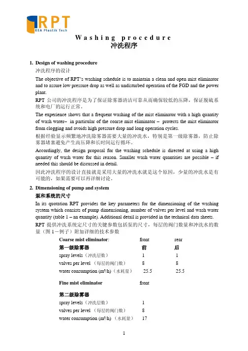
W a s h i n g p r o c e d u r e冲洗程序1.Design of washing procedure冲洗程序的设计The objective of RPT’s washing schedule is to maintain a clean and open mist eliminator and to assure low pressure drop as well as undisturbed operation of the FGD and the power plant.RPT公司的冲洗程序是为了保证除雾器清洁可靠从而确保较低的压降,保证脱硫系统和电厂的运行正常。
The experience shows that a frequent washing of the mist eliminator with a high quantity of wash water– in particular of the coarse mist eliminator – protects the mist eliminator from clogging and avoids high pressure drop and long operation cycles.根据经验显示频繁地冲洗除雾器需要大量的冲洗水,特别是第一级除雾器,防止除雾器堵塞避免产生高压降和长时间运行循环。
Accordingly, the design proposal for the washing schedule is directed at using a high quantity of wash water for this reason. Smaller wash water quantities are possible – if needed this should be discussed in detail.因此冲洗程序的设计直接就是采用大量的冲洗水就是这个原因,少量的冲洗水是有可能的,如果需要可以再详细讨论。
2×660MW燃煤机组烟气脱硫总承包工程吸收塔除雾器安装作业指导书批准:审核:编制:目录1、工程概况 (3)2、编制依据 (3)3、施工组织计划 (4)4、施工前准备 (5)5、安装程序及工艺要求 (6)6、质量控制和验收标准............................ . (9)7、安全文明施工 (14)1、工程概况1.1 工程概述北面和东面为杭宁高速公路、104国道和铁路宣杭线,东临吕山港支流,南临吕山港,西侧紧靠乡级公路,西北侧为乌龟山。
厂址位于铁路宣杭线和吕由港之间场地上。
场地西北面乌龟山脚下为坐山湾村,与厂址场地相隔一条乡级公路;场地西面为高家庄,距离厂址约250m,吕山港南岸的杨吴村,距离厂址约350m,场地东面的施家门村,距离厂址约670m。
工程规模和性质:2×660MW燃煤机组烟气脱硫安装工程。
1.2 主要工程量1.2.1吸收塔主要参数:筒体φ16200/φ18200mm。
1.2.2吸收塔塔内件安装主要工作量2、编制依据2.1《吸收塔制作安装图》 T392S-J03062.2 MUNTERS除雾器安装图纸和安装使用说明书2.3 除雾器技术协议2.4《火电厂烟气脱硫工程施工质量验收及评定规程》 DL/T 5417-20092.5《吸收塔制造技术规范》 GH-FGD011S-RQ00012.6《火力发电厂焊接技术规程》DL/T869 20122.7《电力建设安全工作规程第1部分:火力发电厂》(DL5009.1—2002)2.8《建筑施工高处作业安全技术规范》JGJ80-912.9《施工组织总设计》2.10《火电施工质量检验及评定标准》(加工配制篇)19942.11《钢结构工程施工质量验收规范》 GB50205-20012.12 《电力建设安全健康与环境管理工作规定》20023、施工组织计划3.1施工进度安排单台吸收塔的除雾器安装正常工期为7个工作日。
安排如下:第一天:吊装及安装平台铺设检查;下层冲洗管道及喷嘴预装;下层除雾器部件清理、编号和归类;下层除雾器板吊装,开始塔内组装。
运行说明书OPERATION MANUAL 日期:2010-01 页码1 / 26国电电力酒泉热电厂(2×330MW) 新建工程脱硫岛(EPC)总承包工程MIST ELIMINATOROPERATION MANUAL除雾器运行说明书TYPE: FLAT MEV 25/40型号:平板式MEV25/40END-USER用户:国电电力酒泉热电厂CUSTOMER客户:浙江浙大网新机电工程有限公司SUPPLIER供货商:上海瑞亚安环保设备有限公司运行说明书OPERATION MANUAL 日期:2010-01 页码2 / 26Table of Content目录1.Introduction概述 (3)2.MEV 25/40 -Technical data - 25/40技术参数 (4)2.1Performance of mist eliminator除雾器的性能 (4)2.2Measuring the performance性能保证值的测量 (8)missioning调试 (10)3.1Preparation of commissioning调试的准备工作 (10)3.2Flushing effect冲洗效果 (11)4.Operation and monitoring运行和监控 (11)4.1General aspects总述 (11)4.2Operation运行 (14)4.3Monitoring监控 (15)4.4Washing Procedure冲洗程序 (16)4.5Quality of wash water冲洗水质 (19)4.6Fourth washing level第四级冲洗 (20)4.7Hard scaling硬垢 (22)4.8Flushing operation冲洗 (22)4.9Inspection检查 (23)5.Trouble shooting故障排除 (25)6.RPT After-sales service售后服务 (26)1. Introduction概述This document is intended to support the power plant and FGD operator in the op-eration of the FGD which is equipped with RPT’s MEV 25/40 standard mist elimina-tor.本说明书的目的是帮助电厂和脱硫系统运行人员熟悉和掌握RPTMEV 25/40型除雾器的运行情况。

电除雾器操作规程(最新版)编制人:__________________审核人:__________________审批人:__________________编制单位:__________________编制时间:____年____月____日序言下载提示:该文档是本店铺精心编制而成的,希望大家下载后,能够帮助大家解决实际问题。
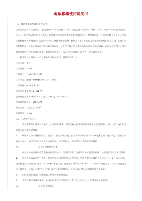
文档下载后可定制修改,请根据实际需要进行调整和使用,谢谢!并且,本店铺为大家提供各种类型的安全管理制度,如通用安全、交通运输、矿山安全、石油化工、建筑安全、机械安全、电力安全、其他安全等等制度,想了解不同制度格式和写法,敬请关注!Download tips: This document is carefully compiled by this editor. I hope that after you download it, it can help you solve practical problems. The document can be customized and modified after downloading, please adjust and use it according to actual needs, thank you!In addition, this shop provides you with various types of safety management systems, such as general safety, transportation, mine safety, petrochemical, construction safety, machinery safety, electrical safety, other safety, etc. systems, I want to know the format and writing of different systems ,stay tuned!电除雾器操作规程1. 目的除去自填料洗涤塔来的炉气中所含的酸雾,使电除雾器出口炉气中含酸雾达到二氧化硫主鼓风机要求的小于0.005g /Nm3,以保证免除对触媒和设备的最小损害。

高效气溶胶静电除雾器使用说明书湖北徐风环保科技有限公司目录第一章概述 (3)第二章设备说明 (3)一、设备本体结构 (3)二、设备本体技术指标一览表................................ 错误!未定义书签。
三、设备本体技术指标可达条件及特点........................ 错误!未定义书签。
第三章高效气溶胶静电除雾器的调试.. (4)一、高效气溶胶静电除雾器的调试组织 (4)二、喷淋系统的调试 (4)三、绝缘子室温控箱的调试 (5)第四章高效气溶胶静电除雾器的操作规定 (8)一、电除雾器投入运行前的检查、确认 (8)二、电除雾器的投入运行 (9)三、电除雾器的联网运行 (9)四、电除雾器清洗操作 (10)五、电除雾器的停车操作 (10)六、电除雾器内部检查、检修操作 (10)七、电除雾器的紧急停车操作 (11)第五章高效气溶胶静电除雾器的检修 (12)一、电除雾器日常巡检内容 (12)二、电除雾器检修 (12)三、电除雾器检修标准及质量要求 (14)第一章概述高效气溶胶静电除雾器是以合成树脂为粘合剂,以玻璃纤维及其制品为增强材料,以碳纤维制品为导电材料而制成的电除雾器。
它具有导电性好、重量轻、耐腐蚀、阻燃性好、性能稳定、效率高等优点。
过去我国烟气净化和尾气处理多采用铅电除雾器和塑料电除雾器(PVC),由于以上两种材料固有的性质,在实际生产中存在许多不足之处。
近年来由于材料工业的发展,技术的进步,碳玻璃钢等新材料的不断出现,国际及国内开始选用更先进的导电玻璃钢材料作为电除雾的主体材料,并且获得成功和收到满意的效果。
为使高效气溶胶静电除雾器能长期高效和稳定地为生产服务,减少非计划停车的时间,防止触电、电场的开路、短路以及人身、设备事故的发生,保持电场的清洁和完好,特制订以下操作手册供操作者和维护检修人员使用,各用户也可根据本操作手册,结合本厂的实际情况及特点,编制相关的操作规程以指导相关人员的工作,确保电除雾器高效、长期安全运行。
活性炭吸附箱使用说明书除雾器使用说明书工作原理在通常的化工操作中所碰到的气体中分散液滴的直径约在0.1~5000μm。
一般粒径在100um以上的颗粒因沉降速度较快,其分离问题很容易解决。
通常直径大于50μm的液滴,可用重力沉降法分离;5μm以上的液滴可用惯性碰撞及离心分离法;对于更小的细雾则要设注街化紧集形成较大颗粒,或用纤维过滤器及静电除雾器。
丝网除沫器,其主要用于分升,通过架在格栅上的金属丝网时,由于雾沫上升的惯性作用,使得雾沫与细丝碰撞而粘附在细丝的表面上。
细丝表面上的雾沫进一步扩散及雾沫本身的重力沉降,使雾沫形成较大的液滴沿着细丝流至它的交织处。
由于细丝的可湿性、液体的表面张力及细丝的毛细管作用,使得液滴越来越大,直至其自身的重力超过气体上升的浮力和液体表面张力的合力时,就被分离而下落,流至容器的下游设备中。
只要操作气速等条件选择得当,气体通过丝网除沫器后,其除沫效率可达到97%以上,可以达到完全去除雾沫的目的。
四、丝网除沫器用丝网除沫器(除雾器)用于分离塔中气体夹带的液滴,以保证有传质效率,降低有价值的物料损失和改善塔后压缩机的操作,一般多在塔顶设置丝网除沫器。
可有效去除3-5μm的雾滴,塔盘间若设置除沫器,不仅可保证塔盘的传质效率,还可以减小板间距。
所以丝网除沫器主要用于气液分离。
亦可为空气过滤器用于气体分离。
此外,除沫器丝网还可维为仪表工业中各类仪表的缓冲器,以防止电波干扰的电子屏蔽器等。
·安装与维护:1.种本产品安装时要确保进出风顺畅,设备进出风口需安装变径。
2.本产品不需供电。
3.本产品需要定期观察除雾器内是否堵塞,如有堵塞可拿出用水清洗即可。
周期一般为半年至一年,视自己使用情况而定。
·注意事项(1)只有在风机设备完全正常的情况下方可运转。
(2)在正常的运转中,除雾器成套装置各活动门必须紧扣。
(3)如风机设备在检查后开动时,则必须注意风机各部位是否正常。
定期检查风机是否正常,防止风机承温度过高而损坏。
蒙特MCS300说明书
瑞士MUNTERS蒙特除湿器/除雾器/除湿机
蒙特除湿系统中采用干燥剂(一种很容易吸收和留住水汽的材料)去除空气中的水分。
干燥转轮除湿机特别适合于低温度和低湿度水平下去除空气中的水分。
瑞士MUNTERS 除湿器在干燥转轮除湿机的中心位置是一个由玻
璃纤维和耐热的陶瓷材料制成的除湿转轮。
当处理空气通过材料凹槽时,接触干燥剂,从而向干燥剂释放水分。
离开转轮时,处理空气变成干燥而排到室内。
吸附处理空气的水分后,饱和的除湿转轮缓慢转至另一股较小的气流以被加热。
这个被称为再生空气的气流使干燥剂变暖;温热的干燥剂释放水分;之后,水分被再生空气排到室外。
被干燥的转轮旋转至待处理空气,再一次吸收水分。
MCS300蒙特干燥转轮除湿机的特点:
模块化设计
使用冷凝器中释放的热量再生干燥转轮,因而非常高效和简便
根据顾客和应用的需求进行设计
可在超低露点(—70℃)进行高效的除湿。
除雾器废气处理使用说明书目录目录 (1)一、概述 (2)二、材质特征 (3)三、结构特点 (4)四、形式特点 (5)五、设计要素 (6)六、工作原理 (7)七、系统构成 (8)一、公司介绍沧州合程环保设备公司是一家集科研、设计、生产、维修、和销售集成为一体的高新技术企业,凭借在环保领域的专业水平和成熟的技术,正在迅速崛起。
依靠科技求发展,不断为用户提供满意的高科技产品,是我们始终不变的追求。
在充分引进吸收国外先进技术的基础上,已成功开发出环保净化设备、粉尘处理设备、废气处理设备、等系列产品,并已广泛应用于冶金、化工、焊接、制药、垃圾处理、喷涂等众多领域。
以一流的产品质量和精湛的技术服务受到了用户的一致好评。
今天我公司全体员工奉行“进取求实严谨团结”的方针,不断开拓创新,以技术为核心、视质量为生命、奉用户为上帝,竭诚为您提供性价比最高的环保产品、高质量的废气粉尘工程设计改造及无微不至的售后服务。
二、材料特性:由于除雾器组件长期工作环境腐蚀量大,要求除雾组件材料具有耐高强腐蚀的能力;除雾器组件长期工作在洗涤后的烟气流道中,被不停的剥蚀和扰动,又要求除雾器组件材料钢性和抗氧化性能好,以确保除雾器组件长期连续运行而不损坏,并保证材料抗老化性能强。
我公司专业化的工程塑料满足了除雾器组件各项特性要求,改性增强型PP符合除雾器组件的物理性能和化学性能的特性要求,材料价格也能使用户满意。
三、结构特点:我公司除露器的结构设计和安装特点是单元组合、每级一体化连接,保证除雾器当运行环境发生瞬间超温或叶片结垢、堵塞使除雾器发生过载时除雾器单元整体或局部不脱落。
四、形式特点:五、设计要素:除雾器是烟气脱硫工艺中的关键设备,从除雾器的设计到除雾器的制造,都必须严格满足烟气脱硫系统运行工程的参数变化要求,最好将参数放大到恶劣运行工况时的最高值。
除雾面积的计算要保证理论计算最佳值得1.4倍,因为它是除雾效率好坏的基础,一般表现在除雾器的叶片片型(两通道或三通道),叶片宽度(或过流长度),叶片布置数量。
DF-52408:B • 11/16/09 — Page 1 of 4BEAM355 and BEAM355SSingle-Ended, Reflected-TypeAddressable Beam Smoke DetectorsAddressable DevicesDF-52408:B • E-270BEAM355withRelective PlateBEAM355withBEAMMMK6975reflect.wmf6975beammmk.wmfGENERALThe FireLite BEAM355 and BEAM355S are intelligent,addressable reflected beam smoke detectors for protecting open areas with high and sloping ceilings, and wide-open areas, where spot-type smoke detectors are difficult to install and maintain. Ideal applications are atriums, cathedral ceilings, aircraft hangars, warehouses, sporting arenas,concert halls, and enclosed parking facilities. They are compatible with the MS-9600 Series and MS9200 Series in LiteSpeed® or CLIP mode. Installation of the single-ended reflective design is much quicker than a dual-ended projected beam detector. Alignment is easily accomplished with an optical sight and a two-digit signal strength meter incorporated into the beam detector. Listed for operation from –22°F to 131°F , the BEAM355 and BEAM355S are usable in open area applications where temperature extremes exceed the design limits of other types of smoke detection.The BEAM355 and BEAM355S are a transmitter/receiver unit and a reflector. When smoke enters the area between the unit and the reflector it causes a reduction in the signal strength.When the smoke level (signal strength) reaches the predetermined threshold, an alarm is activated. The detectors have four standard sensitivity selections as well as two Acclimate® settings. When either Acclimate® setting is selected, the detector’s advanced software algorithms automatically adjust to the optimum sensitivity for the specific environment.The BEAM355S has an integral sensitivity test feature of a filter attached to a servomotor inside the detector optics.Activation of the RTS151 or RTS151KEY remote test stations moves the filter into the pathway of the light beam, testing the detector’s sensitivity. This sensitivity test feature allows the user to quickly and easily meet the annual maintenance and test requirements of NFPA 72, without physical access to the detector. The servomotor must be powered by +24 VDC, not SLC power.FEATURES•Listed to UL 268, ULC CAN/ULC S529.•T ransmitter/receiver built into same unit.•Six user-selectable sensitivity levels.•16' to 328' (use BEAMLRK beyond 230') protection range.•Removable plug-in terminal blocks.•Digital display — no special tools required.•Built-in automatic gain control compensates for signal dete-rioration from dust buildup.•Optional remote test station.•Optional long-range kit (BEAMLRK) for applications in excess of 230' (70 m).•Optional multi-mount kit (BEAMMMK) providing ceiling or wall mount capability with increased angular adjustment.•Optional heater kits (BEAMHK and BEAMHKR) for prevention of condensation (not intended to increase or reduce the specified operating temperature).•Paintable cover.SPECIFICATIONSOPERATIONAL SPECIFICATIONSProtection Range: 16 to 230 feet (5 to 70 m), 230 to 328 feet (70 to 100 m) using optional BEAMLRK kit.Adjustment Angle: ±10° horizontal and vertical. Note that the optics move independently of the unit.Sensitivity (6 levels):NOTE: Sensitivity settings are a feature of specific control panels.•Level 1 — 25%.•Level 2 — 30%.•Level 3 — 40%.•Level 4 — 50%.•Acclimate® Level 5 — 30% to 50%.•Acclimate® Level 6 — 40% to 50%.Fault Condition (trouble):•96% or more obscuration blockage.•In alignment mode.•Improper initial alignment.•Self-compensation limit reached.Alignment Aid:•Optical gunsight.•Integral signal strength indication.•Two-digit display.Indicators:•Alarm — local red LED and remote alarm.•Trouble — local yellow LED and remote trouble.•Normal — local flashing green LED.Test/reset features:•Integral sensitivity test filter (BEAM355S only, requires external power supply).•Sensitivity filter (incremental scale on reflector).•Local alarm test switch.•Local alarm reset switch.•Remote test and reset switch (compatible with RTS151 and RTS151KEY test stations).Smoke Detector Spacing: On smooth ceilings, 30 – 60 feet (9.1 to 18.3 m) between projected beams and not more than one-half that spacing between a projected beam and a sidewall. Other spacing may be used depending on ceiling height, airflow characteristics, and response requirements. See NFPA 72.ENVIRONMENTAL SPECIFICATIONS Temperature: –22°F to 131°F (–30°C to 55°C). Humidity: 10 – 93% RH noncondensing.ELECTRICAL SPECIFICATIONS •Voltage: 15 to 32 VDC.•Average Standby Current (24 VDC): 2 mA maximum (LED flashing, SLC @ 24 V).•Alarm Current (LED on): 8.5 mA maximum.•Trouble Current (LED on): 4.5 mA maximum.•Alignment Current: 20 mA maximum.•External Supply (BEAM355S only):Voltage — 15 to 32 VDCCurrent — 0.5 A maximum.•Remote Output (Alarm):Voltage - 15 to 32 VDC (Output voltage same as device input voltage)Current - 15 mA maximum, 6 mA minimum (Output current is limited by 2.2K ohm resistor)•Heater Kit BEAMHK:Voltage - 15 to 32 V; Current - 92 mA maximum @ 32 V (heater only); Power Consumption-nominal 1.6 W @ 24 V, maximum 3.0 W @ 32 V.•Reflector Heater Kit BEAMHKR: Voltage - 15 to 32 V;Current - 450 mA maximum @ 32 V (per reflector); Power Consumption (per reflector) - nominal 7.7 W @ 24 V, maximum 15.0 W @ 32 V.MECHANICAL SPECIFICATIONSShipping Weight: 3.7 lbs (1.68 kg)Detector Dimensions: 10.0" H x 7.5" W x 3.3" D (254 mm H x 191 mm W x 84 mm D).Reflector Dimensions for 16' to 230' (5 to 70m) Applications: 7.9" x 9.1" (200 x 230 mm).Reflector Dimensions for Applications Beyond 230'/70m: 15.7" x 18.1" (400 x 460 mm).SENSITIVITY SELECTIONThe detector has six sensitivity selections (sensitivity settings are a feature of specific control panels). Each of these selections is only acceptable over a specific distance separation between the detector and the reflector per UL 268. The chart below determines which selections are acceptable for your installed distance. The sensitivity of the detector can be set only when the housing is removed and the detector is not in the fine adjustment step of the alignment mode, indicated by the illumination of the dual digital display. T o set the sensitivity, depress the sensitivity button one time. See Switch Locations diagram. Once the switch is pressed, the digital display will illuminate and read the current sensitivity setting in percent obscuration. To change the sensitivity, continue to depress the sensitivity switch until the desired setting is achieved. The digital display will turn off automatically if no further switch presses occur.In addition to the four standard sensitivity selections, the detector has two Acclimate® settings. When either Acclimate®setting is chosen the detector will automatically adjust its sensitivity using advanced software algorithms to select the optimum sensitivity for the environment. The sensitivity will be continuously adjusted within the ranges specified in the chart above.Total obscuration can be converted to percent per foot, assuming uniform smoke density for the entire length of the beam. The chart below converts total obscuration percent per foot for all acceptable sensitivity settings.SensitivitySettingPercentObscurationDisplayReadingAcceptableDISTANCEbetweenDetectorandReflector(ft)AcceptableDISTANCEbetweenDetectorandReflector(m) Level 125%2516.4 to 120 5.0 to 36.6 Level 230%3025 to 1507.6 to 45.7 Level 340%4060 to 22018.3 to 67 Level 450%5080 to 32824.4 to 100 Acclimate ®Level 130% to 50%A180 to 15024.4 to 45.7 Acclimate ®Level 240% to 50%A280 to 20024.4 to 67Page 2 of 4 — DF-52408:B • 11/16/09DF-52408:B • 11/16/09 — Page 3 of 4Total ObscurationWiring Diagram with RTS151/KEYWiring Diagram6985g r a p h .t i f6985wirerts151.tifAlignment and Adjustment Locations6985a d j l o c .t i fHousing Screw Locations6985s c r e w l o c s .t ifPARTS LISTItem QuantityT ransmitter/Receiver Unit 1Paintable Trim Ring 1Reflector 1Plug-In Terminal Blocks 3Isolator Shunts 2Instruction Manual 1Orange Sticky Paper 1See RTS151/KEY Installation Instructions for electrical ratings of the RTS151/KEYRTS151/KEYPin 1Pin 2Pin 4Pin 3Pin 5Remote Alarm Out AUX (-)Reset Input Test InputSee electrical ratings.or Previous device.32 VDC Maximum Twisted pair is recommendedDevicePage 4 of 4 — DF-52408:B • 11/16/09This document is not intended to be used for installation purposes. We try to keep our product information up-to-date and accurate. We cannot cover all specific applications or anticipate all requirements.All specifications are subject to change without notice.For more information, contact Fire•Lite Alarms. Phone: (800) 627-3473, FAX: (877) 699-4105.Acclimate® is a trademark of Honeywell International Inc.©2009 by Honeywell International Inc. All rights reserved. Unauthorized useof this document is strictly prohibited.AGENCY LISTINGS AND APPROVALSThese listings and approvals apply to the devices specified in this document. In some cases, certain modules or applications may not be listed by certain approval agencies, or listing may be in process. Consult factory for latest listing status.•UL Listed: S1059•ULC Listed: S1059•CSFM: 7260-0075:209•MEA: 143-04-E •FM ApprovedPRODUCT LINE INFORMATIONBEAM355: Intelligent beam smoke detectorBEAM355S: Intelligent beam smoke detector with integral sensitivity test.BEAMLRK: Long range accessory kit (required for applica-tions in excess of 230 ft/70 m).BEAMMMK: Multi-mount kit (provides ceiling or wall mount capability with increased angular adjustment).BEAMSMK: Surface-mount kit.RTS151: Remote test station.RTS151A: Same RTS151 with ULC listing.RTS151KEY: Remote test station with key lock.RTS151KEYA: Same as the RTS151KEY with ULC listing.BEAMHK: Heating kit for use with the transmitter/receiver unit of BEAM355S. For prevention of condensation.BEAMHKR: Heating kit for use with the reflector on BEAM355S. For prevention of condensation6500-MMK: Heavy-duty multi-mount kit for installations prone to vibration or where there is difficulty mounting the set angle.When installed with the transmitter/receiver unit, the 6500-SMK must be used as well.6500-SMK: Surface-mount kit (required when using 6500-MMK to mount transmitter/receiver).BEAMMMK(ceiling or wall mount kit sold sepa-rately)RTS151RTS151KEYBEAMHK6975b e a m m k .j p gr t s 151.w m frts151key.wmf6985hk.tif。