霍尼韦尔TPS3000系统介绍及其应用
- 格式:pdf
- 大小:224.07 KB
- 文档页数:5

ST3000压力变送器美国霍尼韦尔(HONEYWELL)公司于1983年独家率先向全世界推出智能化现场仪表-ST3000 100系列全智能压力变送器!这是对传统现场仪表的一次深刻变革!它为工业自动化仪表及其系统应用,向更高层次的发展奠定了基础。
全智能变送器的问世,开创了现场仪表的新纪元。
美国霍尼韦尔公司,在92年4月6日向中国推出了ST3000/900系列全智能变送器,它具有数字式全智能变送器的全部优越性能,而价格接近传统模拟式常规变送器。
97年底,霍尼韦尔公司又推出可测高温的压力变送器,接收过程温度最高可达150℃。
以及新推出SMV多变量流量变送器。
新的传感器,电子线路以及软件都可提供动能流量补偿,提供流量测量的精度,并用SCT3000组态软件装载到PC上对变送器进行组态主要特点* 高安全、可靠性* 高稳定性、重复性* 高精度* 宽量程比* 宽移率* 宽域温度静压补偿* 过程组态* 完善的自诊断功能* 双向数字通讯* 模拟、数字两种输出方式* 全数字技术TDC3000(TPS)系统简介TDC3000X开放而安全的生产与过程控制系统:•强大与多样性TDC3000集散控制系统,它是TotalPlant全厂一体化开放概念里的一个平台。
通过一个创新的系统结构和开放的通讯环境,TDC3000将过程和现场仪表的管理(控制层)与生产和信息的管理(信息层)集成在一起,形成一个信息与控制的集成系统。
由此,通过一个单一窗口就可以为企业管理者提供各类数据,辅助他们及时地作出经营决策;同时,系统的通用性和可靠性确保了过程运作的安全进行。
•开放与安全性控制层与信息层的结合,主要是靠系统内的两种双处理器模件--------万能工作站(UxS)与应用模件(AxM)来实现。
这两种模件形成了TDC3000结构中称为X-LAYER的X层。
UxS是TDC3000系统的用户界面,符合X WINDOWS/MOTIF工业标准,它向操作者和工程师提供了一个面向现场过程控制与全厂信息的统一窗口;AxM是TDC3000系统内一个高性能且可靠的应用平台,可执行专用的或开放的应用软件。


TPS3000系统 CL程序除雾器冲洗时序控制应用摘要::介绍Honeywell TPS3000系统CL程序时序控制使用和针对脱硫装置除雾器冲洗改造组态过程,子程序使用技巧。
关键词:Honeywell TPS3000 CL程序前言Honeywell TPS3000系统是1995年Honeywell公司推出的第四代集散控制系统,是将之前TDC系统比较使用WINDOWS界面,具有友好的操作和组态界面,较低的硬件维护成本,具有更好的开放性,仍保持之前安全的工业网络能够提供更全面的解决方案。
我公司煤代油装置采用TPS系统自2007年投用,期间多次扩容,一直保持平稳运行证明TPS系统的可靠性强,是DCS系统中典型代表。
CL程序及CL语言-Control Language控制语言,是TPS系统HPM控制器十分重要的控制功能,Honeywell在TPS系统上开发的高级编程语言,用于完成顺控程序和个性化控制策略,它可以实现复杂的控制算法,也可实现常规运算、连锁控制、顺序控制等。
支持批量操作和连续控制策略,可以访问DCS系统所有参数和功能。
CL程序运行在HPM控制器或者APP里。
CL源程序是文本型文件,文件的后缀是CL,需要编译成目标文件后才能被系统使用。
PM点即Prccess Module点,与CL程序绑定,操作CL程序的窗口,用于装载、调试、启动和监视CL程序的执行。
PM点提供内部寄存器供程序使用。
的内部寄存器包括127个标志量寄存器、80个实数寄存器、4个时间寄存器、16个字符串寄存器。
动力车间燃煤锅炉除雾器冲洗装置两套各分为三层控制单元,共18台控制电动执行机构,根据工艺要求时序动作。
原控制方案2小时工艺人员手动启动一次冲洗逻辑程序,工艺人员时常忘记启动或停止冲洗逻辑控制,或者造成脱硫塔液位偏高严重影响脱硫塔烟气指标。
而且根据脱硫塔厂家给出的冲洗执行方案时序更加复杂,原逻辑程序已无法满足工艺要求。
依据厂家给出的控制方案,“自动”冲洗功能投入运行→“Z”控制程序→“Y”控制程序→“X”控制程序→间隔“0.5小时” →“X”控制程序→间隔“0.5小时” →“Y”控制程序→“X”控制程序→间隔“0.5小时” →“Z”控制程序→“X”控制程序→间隔“0.5小时” → “Y”控制程序→“X”控制程序→间隔“0.5小时” →“X”控制程序→间隔“0.5小时”→“Z”控制程序→“Y”控制程序→“X”控制程序…“X”控制程序:开启“一级除雾器下层冲洗A”→“一级除雾器下层冲洗A”开到位→计时“15秒”→关闭“一级除雾器下层冲洗A” → “一级除雾器下层冲洗A”关到位→开启“一级除雾器下层冲洗B”→“一级除雾器下层冲洗B”开到位→计时“15秒”→关闭“一级除雾器下层冲洗B” → “一级除雾器下层冲洗B”关到位→开启“一级除雾器下层冲洗C”→“一级除雾器下层冲洗C”开到位→计时“15秒”→关闭“一级除雾器下层冲洗C” → “一级除雾器下层冲洗C”关到位。
仪表自控系统维护、检测指导书DCS部分自控系统一、霍尼韦尔TPS3000系统1、系统概述TPS(Total Plant Solution)系统是霍尼韦尔公司推出的新一代集散控制系统。
它是将整个工厂信息系统与生产过程控制系统统一在一个平台上的自动化系统。
它具有三层独立的,但又可以整体通讯的网络:计算机局域网PCN、控制管理网TPN(LCN)和过程控制网络(包括UCN、DataHiway)。
在这三层网络中,过程控制网络与控制过程相连,挂在这个网络中的设备从工艺控制过程中进行数据采集和控制;控制管理网络TPN(LCN)连接一些作为高级控制、扩展数据采集和数据分析的模件,它将所有网络联在一起,构成一个整体;计算机局域网PCN 以普通PC机作为操作平台,运行应用软件及Honeywell的一些离线组态软件。
用户可根据具体的控制系统的要求对各网络中的设备以及各设备中的卡件进行配置。
系统网络结构图2、出厂验收测试(FAT)2.1概述出厂验收测试(FAT)是在全部DCS及附属设备生产、组装完成,并内部调试合格后,由甲方对DCS系统硬件及软件在设备组装地进行测试检查和验收。
FAT测试完成后,由参加测试各方形成FAT测试报告,记录测试主要内容、存在的问题、处理方法和完成时间。
FAT主要包括五部分内容:1)硬件检查2)系统检查3)操作站的应用功能检查4)控制站应用功能检查5)其它应用功能检查整个系统在FAT前应该是运转的。
在FAT期间,要做到随时记录要检查的所有项目并记录其结果。
2.2 FAT测试内容2.2.1硬件检查2.2.1.1质量检查目的: 验证是否通过霍尼威尔的质量检查。
参照: 最终确认的《硬件制造规格书》或订货清单。
方法: 检查是否相关的组件都有检验章或合格证,相关组件都应有各自的检验章或合格证。
2.2.1.2系统硬件配置检查目的:各部件及备品备件是否满足订货的要求。
参照:参照《硬件制造规格书》或订货清单的最终版。
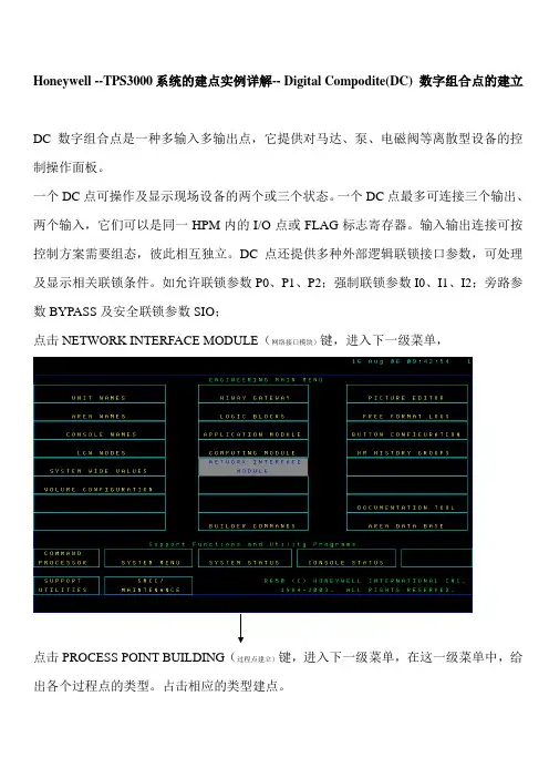
Honeywell --TPS3000系统的建点实例详解-- Digital Compodite(DC) 数字组合点的建立DC数字组合点是一种多输入多输出点,它提供对马达、泵、电磁阀等离散型设备的控制操作面板。
一个DC点可操作及显示现场设备的两个或三个状态。
一个DC点最多可连接三个输出、两个输入,它们可以是同一HPM内的I/O点或FLAG标志寄存器。
输入输出连接可按控制方案需要组态,彼此相互独立。
DC点还提供多种外部逻辑联锁接口参数,可处理及显示相关联锁条件。
如允许联锁参数P0、P1、P2;强制联锁参数I0、I1、I2;旁路参数BYPASS及安全联锁参数SIO;点击NETWORK INTERFACE MODULE(网络接口模块)键,进入下一级菜单,点击PROCESS POINT BUILDING(过程点建立)键,进入下一级菜单,在这一级菜单中,给出各个过程点的类型。
占击相应的类型建点。
点击Digital Compodite 选择框,进入建DC点的组态画面。
NETWORK NUMBER 指UCN网络号例如(NTWKNUM) 6#炉为01NODE NUMBER 指HPM在UCN网络上的地址号如(NODENUM) 6#炉为23 MODVLE NUMBER 指FTA柜中的I/O卡件号6#炉(01-36号)SLOT NUMBER指I/O卡上的点位槽号(SLOTNUM(1-32号)Regulatory PV 常规PV处理点:RPV点提供对过程变量的进一步处理,通过选择相关PV处理算法,可完成输入变量选择、计算流量补偿、流量累加等功能。
每个PV点必须至少有一个输入连接,不能定义输出连接。
RPV点提供的PV处理算法如下图:Regulatory Control Point常规控制算法点RC点提供各种有关标准控制方案的算法,内置了大量控制功能。
1)RC提供的控制算法包括:PID—常规比例积分微分调节PID with feed forward----前馈PIDPID with external reset feedback----带外部预置的反馈的PIDPID with position propotional----带位置比例控制器的PID Position propotional----位置比例控制器Ratio control----比值控制器Ramp sock---爬升/保持控制器Auto/manual station----手动/自动站Increment summer----多个主回路输出变化量加法器Switch---开关选择器Override selector----超驰选择器Multiply/divide----乘法器Summer----加法器2)MODE控制方式选择MAN手动方式:操作员或CK程序决定该点的OP,与控制算法的计算结果无关。
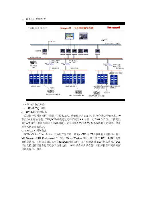
1.自备电厂系统配置LCN网络及节点介绍一. TPN(LCN) 网络(1)TPN(LCN)网络结构总线拓扑型网络结构,采用串行通讯方式,传输速率为5M/秒,网络介质是同轴电缆,40节点/30米同轴电缆。
TPN(LCN)网缆通过光纤扩展至4.9 公里,允许64个节点,广播类型的LAN网络,利用令牌环传递(逻辑环),冗余电缆LCN A/LCN B遇故障时自动切换,保证整个系统运行的稳定。
(2) TPN(LCN)网络设备GUS:Global User Station 全局用户操作站。
功能:GUS是TPS系统的人机接口,基于MS Windows 2000 Professional 平台的,Native Window窗口,用于整个TPN(LCN)系统的信息访问。
过程信息通过实时TPN(LCN)网络访问,工厂信息通过UCN网络访问,GUS 平台支持过程操作和过程组态及设计功能。
GUS操作站为操作员、工程师提供不同的画面以供其操作、组态。
(3)网络接口模件NIM(Network Interface Module)提供LCN网络访问UCN 网络的接口,完成LCN网和UCN网间的数据交换。
(4)历史模件HM(History Module)为TPS系统提供大容量存储器的一个模件,相当于文件服务器。
它可以记录连续的过程历史、事件历史、区域数据库、系统软件(TLK1等)、用户应用软件等。
(5)应用模件AM(Application Module)提供了高一级控制和计算算法,其是LCN上的模件,能实现复杂控制,并通过HPM实现,除一组标准的算法外,允许用户使用CL程序开发用户的算法和控制策略。
锅炉蒸汽流量,厂外供汽流量通过在AM编写CL语言计算得出,详见附表1.二. UCN网络及节点介绍(1) UCN网络结构UCN网络是一条控制网络,通过NIM节点(HPM)实现与LCN的通讯和协议转化。
(2) UCN 网络a)UCN网络传输速率:5M/秒b)UCN网络通讯协议:兼容IEEE(802.4)和ISO标准,载波通讯,令牌环传递c)UCN网络传输介质:75欧姆同轴电缆,冗余d)UCN网络拓扑结构:干线和支线拓扑e)UCN网络设备:32对冗余设备(2) UCN网络组件1.电缆:干线电缆:网络的主干通道,75欧姆RG-11同轴电缆。


ST 3000 Smart TransmitterSeries 100 High Temperature GP ModelsSTG14T, STF14T 0-500 psig / 0-35 barg34-ST-03-707/04Specification and Model SelectionGuideIn 1983, Honeywell introduced the first Smart Pressure Transmitter ― the ST 3000®. In 1989, Honeywell launched for smart field devices. Today, Honey-well transmitters demonstrate proven reliability in hundreds on installations in a wide variety of industries and applica-tions. For applications requiring direct connection to processes requiring small flange, small sanitary connec-tions or 1/2” NPT, Honeywell offers the STG14T transmitter. Applications in-clude gauge pressure for reaction ves-sels in the chemical industry as well as level applications in both the chemical and hydrocarbon processing industries with a relatively high process tempera-ture of 302F (150C). Applications for the food and pharmaceutical industries typically use sanitary connections and M-20 fill fluid.All ST 3000 transmitters can provide a 4-20 mA output, Honeywell Digitally Enhanced (DE) output, HART * output, or F OUNDATION ™ Fieldbus output. When digitally integrated with Honey-well’s Process Knowledge System™, EXPERION PKS™, ST 3000 instru-ments provide a more accurate proc-ess variable as well as advanced diag-nostics.S100 transmitters lead the industry in: • Accuracy • Stability • Reliability • Rangeability • WarrantyIncludes Lifetime Tranmsitters: • Accuracy = +/-0.0375%• Stability = +/-0.01% per year • Reliability = 470 years MTBF • Rangeability = 400 to 1• Lifetime Warranty = 15 yearsFigure 1—Series 100 High Temperature GP Transmitters feature proven pie-zoresistive sensor technology.The devices provide comprehensive self-diagnostics to help users maintain high uptime, meet regulatory requirements, and attain high quality standards. S100 transmitters are ideal for critical applications, such as custody transfer of natural gas and energy and material bal-ances, where accuracy and stability are of the utmost importance."Our commitment to Honeywell field instruments is based on seam-less integration with our Honeywell system and the enhanced fault detection that the Honeywell DE protocol offers. Honeywell instru-ments also offer us a better way of ensuring database integrity over simple analog instruments. In addition, Honeywell's high-quality sup-port has enabled us to better implement solutions to some of ourmore difficult problems. We have used Honeywell differential pressure smart transmitters for the past eight years. Based on their accuracy and low failure rates, we are now targeting critical flow applications that require the robustness that these transmitters bring.” DCS Systems EngineerInternational Integrated Oil CompanyIntroduction34-ST-03-70 Page 2Description FeaturesThe ST 3000 transmitter can replace any 4 to 20 mA output transmitter in use today and operates over a standard two-wire system.The measuring means is a piezoresistive sensor, which actually contains three sensors in one. It contains a differential pressure sensor, a temperature sensor, and a static pressure sensor.Microprocessor-based electronics provide higher span-turndown ratio, improved temperature and pressure compensation, and improved accu-racy.The transmitter’s meter body and electronics housing resist shock, vibra-tion, corrosion, and moisture. The electronics housing contains a com-partment for the single-board electronics, which is isolated from an inte-gral junction box. The single-board electronics is replaceable and inter-changeable with any other ST 3000 Series 100 or Series 900 model transmitter.Like other Honeywell transmitters, the ST 3000 features two-way com-munication between the operator and the transmitter through our Smart Field Configurator (SFC). You can connect the SFC anywhere that you can access the transmitter signal lines.The SCT 3000 Smartline® Configuration Toolkit provides an easy way to configure instruments using a personal computer. The toolkit enables configuration of devices before shipping or installation. The SCT 3000 can operate in the offline mode to configure an unlimited number of de-vices. The database can then be loaded downline during commissioning. • Choice of linear or square root output conformity is asimple configuration selec-tion.• Direct digital integration with Experion PKS and other con-trol systems provides localmeasurement accuracy to thesystem level without addingtypical A/D and D/A converterinaccuracies.• Unique piezoresistive sensor automatically compensatesinput for temperature andstatic pressure.Added “smart”features include configuringlower and upper range val-ues, simulating accurate ana-log output, and selecting pre-programmed engineeringunits for display.• Smart transmitter capabilities with local or remote interfac-ing means significant man-power efficiency improve-ments in commissioning,start-up, and ongoing mainte-nance functions.34-ST-03-70 Page 334-ST-03-70 Page 4Specifications34-ST-03-70Page 5Ambient Temperature De-ratingSilicone Fill Fluid Neobee Fill FluidProcess temperatures above 125 °C (257 °F) require de-rating the ambient limit as follows:Process temperatures above 85 °C (185 °F) require de-rating the ambient limit as follows:Process Temperature Ambient TemperatureLimit Process Temperature Ambient TemperatureLimit150 °C (302 °F) 140 °C (284 °F) 125 °C (257 °F)50 °C (122 °F)60 °C (140 °F)85 °C (185 °F)110 °C (230 °F)100 °C (212 °F)85 °C (185 °F)50 °C (122 °F)60 °C (140 °F)75 °C (167 °F)Performance Under Rated Conditions* -* Performance specifications are based on reference conditions of 25°C (77°F), 10 to 55% RH, and 316L SS diaphragm. ** Transmitter URL limit or maximum process connection rating, whichever is lower.34-ST-03-70Page 6Performance Under Rated Conditions – General for all ModelsParameter Description Output (two-wire) Analog 4 to 20 mA or digital communications DE mode. Options available forF OUNDATION Fieldbus and HART protocol.Supply Voltage Effect ±0.005% span per volt.Damping Time Constant Adjustable from 0 to 32 seconds digital damping.EMC Classification Group 1, Class A, ISM Equipment (EN 55011, emissions), Industrial Equipment (EN50082-2, immunity)CE Conformity (Europe) 89/336/EEC, Electromagnetic Compatibility (EMC) Directive.Lightning Protection Option (Code “LP”) Leakage Current: ***********************,93°CImpulse Rating: 10/20 µ sec. 5,000 Amps (50 strikes) 10,000 Amps (20 strikes) (rise/decay) 10/1000 µ sec. 250 Amps (1000 strikes) 500 Amps (400 strikes)Physical and Approval BodiesParameter Description Process Interface See Model Selection Guide for Material Options for desired process connection.Diaphragm Materials (wetted) 316L Stainless SteelGasket Ring Materials (wetted) 316L Stainless SteelMounting Flange (non-wetted) 316 Stainless Steel.Fill Fluid Silicone (DC 200) or Neobee (M20)Electronic Housing Epoxy-Polyester hybrid paint. Low copper-aluminum alloy. Meets NEMA type 4X(watertight) and designed to meet NEMA 7 (explosion proof).Process Connections Process Head: 1/2-inch NPT.Sanitary: 2” Sanitary Tri-Clamp.Flange: 1/2”, 1”, 1 1/2” and 2” 150# or 300# ANSI flange.Wiring Accepts up to 16 AWG (1.5 mm diameter).Mounting 1/2-inch NPT, sanitary seal, or flange mount connection.Dimensions See Figures 4 to 6Net Weight 7 pounds (3.2 Kg) to 15 pounds (7 Kg)Approval Bodies- Hazardous Areas- Canadian RegistrationNumber (CRN) Approved as explosion proof and intrinsically safe for use in Class I, Division 1, Groups A, B, C, D locations, and nonincendive for Class I, Division 2, Groups A, B, C, D locations. Approved EEx ia IIC T4, T5, T6 and EEx d IIC T5, T6 per ATEX standards. See attached Model Selection Guide for options.- All ST 3000 model designs, except STG19L, STG99L, STG170, STG180, have been registered in all provinces and territories in Canada and are marked CRN: 0F8914.5C.Table continued on next page ⇒34-ST-03-70Page 7Physical and Approval Bodies, continuedParameter DescriptionPressure Equipment Directive (97/23/EC) The ST 3000 pressure transmitters listed in this Specification have no pressurized internal volume or have a pressurized internal volume rated less than 1,000 bar (14,500 psig) and/or have a maximum volume of less than 0.1 liter. Therefore, these transmitters are either; not subject to the essential requirements of the directive97/23/EC (PED, Annex 1) and shall not have the CE mark, or the manufacturer has the free choice of a module when the CE mark is required for pressures > 200 bar (2,900 psig).NOTE: Pressure transmitters that are part of safety equipment for the protection of piping (systems) or vessel(s) from exceeding allowable pressure limits, (equipment with safety functions in accordance with Pressure Equipment Directive 97/23/EC article 1, 2.1.3), require separate examination.Figure 4 Typical mounting dimensions for 1/2-inch NPT connection models for reference.34-ST-03-70 Page 8Figure 5 Typical mounting dimensions for flush sanitary seal connection models for reference.34-ST-03-70Page 9Figure 6 Typical mounting dimensions for small flange connection models for reference.34-ST-03-70 Page 10Options Ordering Information Indicating Meter(ME and SM Options)Two integral meter options are available. An analog meter (option ME) is available with a 0 to 100% linear scale. The Smart Meter (option SM) provides an LCD display for both analog and digital output and can be configured to display pressure in pre-selected engineering units.Lightning Protection (Option LP)A terminal block is available with circuitry that protects the transmitter from transient surges induced by nearby lightning strikes.HART Protocol Compatibility (Option HC)An optional electronics module is available for the ST 3000 that provides HART Protocol compatibility. Transmitters with the HART Option are compatible with the AMS System. (Contact your AMS Supplier if an upgrade is required.)Transmitter Configuration (Option TC)The factory can configure the transmitter linear/square root extraction, damping time, LRV, URV and mode (analog/digital) and enter an ID tag of up to eight characters and scratchpad information as specified. Lifetime Warranty(Option WL)Extends limited 1-year warranty policy to 15 years for ST 3000S100 pressure transmitters. See Honeywell Terms and Conditions.Indicator Configuration(Option CI)Provides custom configuration ofSmart MetersTagging (Option TG)Up to 30 characters can be addedon the stainless steel nameplatemounted on the transmitter’selectronics housing at no extra cost.Note that a separate nameplate onthe meter body contains the serialnumber and body-related data. Astainless steel wired on tag withadditional data of up to 4 lines of 28characters is also available. Thenumber of characters for taggingincludes spaces.Custom Calibration and ID inMemory (Option CC)The factory can calibrate any rangewithin the scope of the transmitter’srange and enter an ID tag of up toeight characters in the transmitter’smemory.F OUNDATION Fieldbus(Option FF)Equips transmitter with FF protocolfor use in 31.25 kbit/s FF networks.See document 34-ST-03-72 foradditional information on ST 3000Fieldbus transmitters.Contact your nearest Honeywell sales office,orIn the U.S.:HoneywellIndustrial Automation & Control16404 North Black Canyon Hwy.Phoenix, AZ 850531-800-288-7491In Canada:The Honeywell Centre155 Gordon Baker Rd.North York, Ontario M2H 3N71-800-461-0013In Latin America:Honeywell Inc.480 Sawgrass Corporate Parkway,Suite 200Sunrise, FL 33325(954) 845-2600In Europe and Africa:Honeywell S. A.Avenue du Bourget 11140 Brussels, BelgiumIn Eastern Europe:Honeywell Praha,s.r.o. Budejovicka 1140 21 Prague 4,Czech RepublicIn the Middle East:Honeywell Middle East Ltd.Khalifa Street,Sheikh Faisal BuildingAbu Dhabi, U. A. E.In Asia:Honeywell Asia Pacific Inc.Honeywell Building,17 Changi Business Park Central 1Singapore 486073Republic of SingaporeIn the Pacific:Honeywell Pty Ltd.5 Thomas Holt DriveNorth Ryde NSW Australia 2113(61 2) 9353 7000In Japan:Honeywell K.K.14-6 Shibaura 1-chromeMinato-ku, Tokyo, Japan 105-0023Specifications are subject to change without notice Or, visit Honeywell on the World WideWeb at: 34-ST-16-47 Issue 14**The user must determine the type of protection required for installation of the equipment. The user shall then check the box [D] adjacent to the type of protection used on the equipment certification nameplate. Once a type of protection has been checked on the nameplate, the equipment shall not then be reinstalled using any of the other certification types.This Page Intentionally BlankST 3000 is a registered trademark of Honeywell International Inc.HART* is a trademark of the Hart Communication Foundation.FOUNDATION™ is a trademark of the Fieldbus Foundation.Industrial Measurement and ControlHoneywell International Inc.2500 W. Union Hill Drive,Phoenix, Arizona 85027 Honeywell International Inc.。
工业装置的Honeywell TPS控制系统介绍一、TPS系统的网络PCN:Plant Control Network 工厂控制网,也就是计算机局域网TPN(LCN):TPS Process Network (Local Control Network)TPS过程网络我们习惯于叫LCN。
它是过程管理网。
UCN:Universal Control Network 万能控制网,也就是过程控制网。
二、主要设备及功能简介:1、LCN网络设备:A、GUS—Global User Station全局用户操作站功能:GUS是TPS系统的人机接口,基于Windows 2000操作系统工作站平台的Native Window 窗口,用于整个TPN(LCN)系统的信息访问。
过程信息通过实时TPN(LCN)网络访问,工厂信息通过PCN网络访问,GUS平台支持过程操作工程组态及设计功能。
B、HM—History Module历史模件功能:文件服务器C、NIM:Network Interface Module 网络接口模件,它既是TPN(LCN)上的设备,又是UCN 上的设备。
功能:提供TPN(LCN)网络访问UCN网络的接口。
转换TPN(LCN)的通讯技术和协议到UCN的通讯技术和协议。
D、APP:Advanced Processing Platform 应用处理平台功能:采集系统实时数据,并可将经过计算后的数据再回写到回系统中2、UCN网络设备:A、NIM NIM:Network Interface Module 网络接口模件B、HPM: High Performance Process Manager 高性能过程管理器功能:HPM是一个控制设备,通过UCN网络连接到TPS系统中。
它具有快速的内部处理器和大内存容量,扫描和控制TPS系统过程数据。
三、主要状态画面系统状态画面,如下图所示系统状态画面在系统状态画面上显示LCN网络电缆的状态及LCN网的全部设备的状态。
60万吨/年加氢裂化装置DCS ----HONEYWELL TPS系统操作规程TPS系统DCS即Distributed Control System集散型计算机控制系统,又名分布式计算机控制系统,其实质是利用计算机技术对生产过程进行集中监视,操作,管理和分散控制的一种控制技术。
加氢裂化装置DCS系统为Honeywell公司的TPS系统,以Windows NT 或Windows 2000 为基本操作系统平台,具有开放性强、用户界面友好、方便与第三方软件通讯的优点。
TPS系统是一个多层通讯网络结构系统,由PIN网、LCN网、UCN网及其挂在上面的模件组成,系统配置灵活,可扩展性强。
其中TPS是Total plant system全厂一体化系统的缩写。
一、几个基本概念:1.GUSGUS是Globel User Station的缩写,GUS属于TPS系统中LCN节点,是TPS系统的HMI--人机接口,它通过LCNP卡连接到TPN网络。
本装置有七台GUS,其中一台为工程师站(GUS1)。
2.单元TPS系统组态时,要求对所组态的参数进行事先分单元,每一个点在组态过程都要求根据其物理位置确定其单元,以便对同一单元的点进行管理;例如在一个单元处于停工状态时,可以禁止此单元的报警信息,为此,将装置各岗位划分单元如下:3.区域一个区域可以包括多个单元,也可以包括多台GUS,不同的区域有不同的区域数据库,必须组态不同的自定义键,以及操作组。
本系统划分三个区域:分馏区域、PSA和机组区域、公用和反应区域。
一个区域所包含的GUS只能操作控制属于这个区域的单元中的点。
否则系统会提示“UNIT NOT ASSIGN”的错误,表示这个点所在的单元不属于这台GUS所在的区域,不能操作。
二、TPS系统的基本操作方法每台GUS在启动后会自动以操作员权限登录,可以设置自动LOAD(装载)GUS 属性和NCF 文件,也可以手动。
文件装载完成后,可以以两种方式进行操作:Native Window 或流程图画面,不管哪种操作方式都必须使用操作员键盘。
Honeywell--TPS3000系统的建点实例详解-- Builder Command命令的使用详解命令如下图:举例说明各项功能:1)RECONSTITUTE:将HPM中运行的某个点读到GUS或US的PED画面中,就是把控制站的一点调到操作站的画面上来。
点击该选项,在第二行内建入位号名称后回车,该点调出。
2)WRITE TO IDF:在NIM中新建一个点(前面课已讲过,不再重复),在这里定义点名为PV001A。
在组态结束时按CTRL+F12将该点装入HPM中,这时不要关闭组态画面,按COMMAND键回到BUILDER COMMAND画面中,点击WRITE TO IDF选项,如下图所示;第一行指出HM路径,也就是将该点存入HM哪个目录中。
第二行不选,第三行为自己定义的文件名,上图所示就是将该点存入到HM的DB1目录下的HPM17AO文件中,生成一个DB文件。
这时,使用命令处理器可看到在HM的DB1目录下生成HPM17AO.DB文件。
如下图所示号为PV001A)读到PED画面中来,见下图这时又进入PV001A的组态画面。
4)LIST ENTITES IN IDF:列出HM硬盘中DB1目录下HPM17AO.DB文件下的所有点的位号。
首先,分别再建三个AO点(位号定义为PV001B、FV001、FV002),这些点都建在17号HPM中。
把它们按第二项所讲都存入HM的DB1目录下的HPM17AO.DB文件中。
如下图:回车确认后会出现下图:这一步的含义是把HM中DB1目录下的HPM17AO.DB 中的多点以列表的形式读到当前的画面上。
同时在HM中DB1目录下生成一个HPM17AO.XX文件。
如下图5)LIST ENTITES IN MLDULE:列出11号HPM中所有PID控制点的位号。
同时在HM中DB1目录下生成一个HPM11PID.XX文件6)DELETE SYS ENTITES:删除HPM中的某一个点在第二行直接键入位号回车即可,但该点必须处于非激活状态。
霍尼韦尔ST3000系列差压变送器介绍
霍尼韦尔ST3000系列差压变送器介绍
ST3000系列差压变送器是以微处理器为基础的智能变送器,最新推出的R300版本,全⾯提升了变送器的精度,可靠性及长期稳定性指标。
它能测量各种液体和⽓体的差压、流量、压⼒或液位,并输出对应的4~20mA模拟信号和数字信号。
它独特的温度和静压误差⾃动修正功能使其能满⾜苛刻的使⽤环境。
它具有DE通讯协议,可与霍尼韦尔的Experion PKS集散控制系统和智能现场通讯器(SFC)实现双向数字通讯,消除了模拟信号传输误差,⽅便了变送器的调试、校验和故障诊断。
技术特点
1、先进的传感器技术
采⽤离⼦注⼊硅技术,在差压传感器上集成了静压和温度传感器,随时修正过程温度和静压引起的误差,提⾼了测量精度和稳定性
2、⾼可靠性:平均⽆故障时间470年。
3、⾼稳定性:±0.01%/年
4、⾼精度:±0.065%。
5、耐精压⾼:普通型为21MPa,最⾼可达42MPa
6、测量范围宽:
STD924 0-100KPa
STD930 0-700KPa
STD974 0-21MPa
7、规格齐全:接液部分有各种防腐材料备选,能满⾜各种⼯况条件下的使⽤。
测量对象
1、差压测量
2、压⼒测量(低压端通⼤⽓)
3、与节流装置配合进⾏流量测量
4、液位测量(⾮粘稠/⾮结晶液体)
5、界⾯测量(⾮粘稠/⾮结晶液体)。
H o n e y w e l l T P S系统简述TPS是Honeywell公司于九五年推出的新一代融合过程控制网络,实时操作网络和工厂信息网络管控一体化的控制系统。
该系统继承了传统DCS系统的全部优势,同时将商业管理信息融合进工艺控制之中,进而为企业决策、减低产品成本、提高产品竞争力提供基础平台。
TPS系统是一个多层通讯网络结构系统,由PIN网、LCN网、UCN网及其挂在上面的模件组成,系统配置灵活,可扩展性强,通过相应的网桥,可以与第三方产品实现无缝集成。
该系统广泛应用于生化、石化、工业电站、冶炼等行业。
TPS的组成可参见图1:图1标准的TPS由三个网络组成,PIN、LCN、UCN。
和前代的产品TDC3000(SSP21、22现使用的DCS系统)相比,TPS增加了一个PIN网,用以实现不同DCS系统的数据访问,从而实现全厂一体化。
职以为在TPS系统中最有质的进步的是GUS(Global User Station)的使用。
GUS是基于WIN NT的DCS操作系统,利用PC的通信技术实现PIN网络的功能,同时又使用专门的LCNP主板实现与LCN网络的通信,集操作站和网桥的功能于一身。
以下是我对这门课程各篇章的理解。
一、系统硬件、软件按照设备所处的网络,在LCN网络上的设备可以有:GUS:Global User Station 全局用户操作站,TPS的人机接口,使用基于MSNT工作站平台的Native Window,用于整个LCN系统的访问。
过程信息通过LCN网络访问,工厂信息通过PIN网络访问,GUS平台支持过程操作和过程工程组态及设计功能。
在GUS上运行的软件有Native Window、Display Builder(流程图制作软件)及其它相关软件。
NIM:Network Interface Module 网络接口模件,提供LCN网络访问UCN网络的接口HM:History Module 历史模件,实现文件服务器的功能,存储系统的组态设置文件、相关设备的属性软件、历史采集数据及用户自定义文件。