tyco连接器样本
- 格式:pdf
- 大小:3.94 MB
- 文档页数:60

Plugs andPlug-In Connectionso k e n f e e : €5.00y CATALOG 2005|2006Reliable contacts in all respectsIrrespective of conditions,Bosch plug-in connec-tions always comply fully with all electrical,mechani-cal,and geometrical stipulations.They guarantee extremely low contact resistance throughout the vehicle’s complete service life,and have very high in-sulation resistance,as well as being watertight and proof against humidity and saline fog.Bosch plug-in connections are easily pluggable and unpluggable,and the connection of wires and terminals is an easy matter.The standard for maximum reliabilityLow-way plug-in connectionsPlug-in connections serve to transfer signals and power to electronic and/or electrical components.The ever-increasing use of electronic components in the vehicle leads to an attendant increase in the demands made on connection reliability.High Contact Reliabilitywith Bosch Plug-In Connections3-way “Compact plug 3”with secondary contact locking and CPA (Connector Position Assume)The lever/slide principle for simple assemblyNew plug-in techniques:The 64-way plug-in connectionOn our 64-way plug-in connection too,the fact that the lever/slide combination permits low opera-ting forces contributes to uncomplicated,high-speed assembly.At the same time,it ensures high levels of reliability when the plug is in position.In those cases in which installation space is limited,the plug can also be inserted without the lever,and only the slide is needed.Low-way plug-in connections –no other plug can compare with our 38-pole plug-in connectionWith its 38-pole plug-in connection,Bosch hasintroduced an innovation to the market:This plug-in connection features 2.5 mm contact spacing and 3.0 mm row spacing.It has been specially designed for hybrid ECU’s which are directly attached to the engine.The swivel-type metal lever reduces the plug-in force to less than 100 N,so that there are no difficulties involved in plugging-in on the vehicle and during service in the workshops.A mechanical coding function makes false plugging pact design with high resistance to vibration.64-way plug-in connection for electronic gasoline-engine managementTwo 38-way passenger-car plugs for MotronicCode A B C Colour Order Number Terminals17.0––black 1 928 403 137Junior Power Timer 17.0––blue 1 928 403 126(see page 22)2 4.0––grey 1 928 403 722Code A B C Colour Order Number Terminals19.0––black 1 928 403 110Junior Power Timer 19.0––grey 1 928 403 915(see page 22)2 5.0––grey 1 928 404 550Code A B C D Colour Order Number Terminals120.0––13.0black 1 928 403 146Junior Power Timer 520.0––11.5black 1 928 403 813(see page 22) Code A B C Colour Order Number Terminals124.0––black 1 928 403 202Junior Power Timer 211.0––grey 1 928 403 816(see page 22)Code A B C Colour Order Number Terminals17.0––black 1 928 403 698Junior Power Timer 17.0––colourless 1 928 404 476(see page 22)2 4.0––grey 1 928 403 9203 5.5– 3.5colourless 1 928 404 707Code A B C Colour Order Number Terminals19.0––black 1 928 403 870Junior Power Timer(see page 22)Code A B C D Colour Order Number Terminals120.0––13.0black 1 928 404 221Junior Power Timer 520.0––11.5black 1 928 404 219(see page 22) Code A B C Colour Order Number Terminals124.0––black 1 928 404 629Junior Power Timer 111.0––grey 1 928 404 631(see page 22)Code A B C Colour Order Number Terminals17.0––black 1 928 403 192Junior Power Timer 17.0––blue 1 928 403 194(see page 22) Code A B C Colour Order Number Terminals19.0––black 1 928 403 196Junior Power Timer 19.0––grey 1 928 403 914(see page 22)Code A B C D Colour Order Number Terminals120.0––13.0black 1 928 403 200Junior Power Timer 520.0––11.5black 1 928 403 812(see page 22) Code A B C Colour Order Number Terminals124.0––black 1 928 403 204Junior Power Timer 211.0––grey 1 928 403 815(see page 22) Code A B C Colour Order Number Terminals129.0––black 1 928 403 222Junior Power Timer(see page 22)Code A B C Colour Order Number Terminals17.0––black 1 928 404 072Bosch Damping Terminal(see page 22)Code A B C Colour Order Number Terminals19.0––black 1 928 404 073Bosch Damping Terminal19.0––grey 1 928 404 074(see page 22)Code A B C Colour Order Number Terminals112.0––black 1 928 404 7451Bosch Damping Terminal112.0––black 1 928 404 8252(see page 22)With special seal.Code A B C D Colour Order Number Terminals120.0––13.0black 1 928 404 075Bosch Damping Terminal(see page 22)Code A B C Colour Order Number Terminals17.0––black 1 928 403 874Bosch Damping Terminal 17.0––brown 1 928 403 876(see page 22)2 4.0––black 1 928 404 1142 4.0––white 1 928 403 8783 5.5– 3.5grey 1 928 404 2134 5.5 3.5–blue 1 928 404 215Code A B C Colour Order Number Terminals19.0––black 1 928 403 966Bosch Damping Terminal 19.0––blue 1 928 403 970(see page 22)2 5.0––black 1 928 403 968Code A B C Colour Order Number Terminals112.0––black 1 928 403 736Bosch Damping Terminal(see page 22)Code A B C D Colour Order Number Terminals120.0––13.0black 1 928 403 738Bosch Damping Terminal 520.0––11.5black 1 928 403 836(see page 22)Code A B C Colour Order Number Terminals124.0––black 1 928 403 740Bosch Damping Terminal 211.0––grey 1 928 404 525(see page 22)Code A B C Colour Order Number Terminals129.0––black 1 928 403 742Bosch Damping Terminal(see page 22)Code A B C Colour Order Number Terminals19.0––black19284034361Junior Power Timer(see page 22) Code A B C Colour Order Number Terminals112.0––black19284034401Junior Power Timer 112.0––black19284034412(see page 22) Code A B C D Colour Order Number Terminals520.0––11.5black19284042251Junior Power Timer(see page 22)Code A B C Colour Order Number Terminals19.0––black19284038092Junior Power Timer(see page 22)Code A B C Colour Order Number Terminals17.0––black1928404166Bosch Damping Terminal 17.0––brown1928404570(see page 22)2 4.0––white1928404571Code A B C Colour Order Number Terminals19.0––black1928404163Bosch Damping Terminal 2 5.0––black1928404368(see page 22)19.0––blue1928404572Code A B C Colour Order Number Terminals112.0––black1928404160Bosch Damping Terminal(see page 22)Code A B C D Colour Order Number Terminals520.0––11.5black19284043701Bosch Damping Terminal 520.0––11.5black19284045982(see page 22)Code A B C Colour Order Number Terminals124.0––black19284046481Bosch Damping Terminal(see page 22)Dimensions l x w x h38x2 Offer drawing number C227 Order number1928401Dimensions l x w x h88x2x8 mm Offer drawing number C280202198 Order number1281099005Dimensions l x w x h88x2x8 mm Offer drawing number C 280 204 853 Order number 1 928 400 889gold-plated, for FLR wires gold-plated, for FLR wires gold-plated, for FLR wires964 972-1Insulation ØOrder No. 963 292-1Dimensions l x w x h80x42x28 mm Offer drawing number D928 003 25A Order number1928404513 without leverDimensions l x w x h80x42x25 mm Offer drawing number C928 002 84A Order number1928404322AMP Junior Power Timerwith additional steel springwith additional steel springwith additional steel spring。
连接器品牌大全,国内外知名连接器品牌排行榜一、全球连接器市场规模稳步上升连接器是系统或整机电路单元之间电气连接或信号传输必不可少的关键元器件,目前连接器已形成一个规范化的产业,连接器的应用范围非常广泛!主要市场是在汽车、电脑、电信、工业、消费类电子、航天航空和军事领域。
二、接插件也叫连接器。
国内也称作接头和插座,一般是指电器接插件。
即连接两个有源器件的器件,传输电流或信号。
公端与母端经由接触后能够传递讯息或电流,也称之为连接器。
全球知名的部分连接器厂家如下:1.TE &Tyco 泰科(AMP)总部:美国全球最大的连接器生产厂家,连接器行业的唯一入围世界500 强的企业。
TEConnectivity (TE) 是一家全球化的公司,公司设计和制造的约50 万种产品,产业分布较广,几乎所有方面的连接器都有涉入。
主要产品应用在消费类电子,电力,医疗,汽车,航空航天以及通讯网络方面(AMP( 安普)是Tyco( 泰科)电子公司的一个着名品牌)。
2.FCI (法马通)总部:法国FCI 是世界范围内电子连接器的主要设计者、生产商和供应商,其产品应用于汽车、通信、消费类电子、数据处理、工业机械等广大领域。
目前FCI 为全球第四大品牌电子连接器,FCI 以其超过十万种产品服务全球,产品主要包括通讯、电源、医疗等连接器标准品,以及薄膜开关,FPCA、PCBA ,线束组装件、注塑电缆组装件,光纤,散热器等增值产品。
3.Amphenol (安费诺)总部:美国安费诺公司手机连接器第一大厂,最擅长的精密接口连接,如SIM 卡连接器,SD 卡连接、USB 连接、HDMI 连接、RF转换等。
通过合并收购笼络了全球很多顶尖的连接器厂家。
产品主要在军工,航空,航天,通信方面比较有优势。
4.MOLEX (莫仕)总部:美国MOLEX 公司是全球领导先的全套互联产品厂厂家。
产品主要应用于电子,电气和光纤。
以开发世界最小型的连接器而知名。

全球最赚钱35家连接器厂商都在这儿(附代理商名单)目前,全球连接器市场主要被泰科、莫仕、FCI以及安费诺等国际巨头把持,这些国际大厂引领着全球连接技术潮流。
作为全球连接器最大的消费市场,中国本土厂商近年也在悄然崛起。
中国本土连接器厂商大致可分为国营和民营两种:国企一般主打航空、军用及工业级产品,代表有中航光电、四川华丰、航天电器等。
民企主要扎根在消费类电子、汽车以及通讯市场,阵营代表主要有立讯精密、得润电子、长盈精密、江苏吴通、宁波凯峰等。
全球最赚钱35家连接器厂商1、泰科电子(TE Connectivity)1999年,Tyco International 与AMP合并,同年又并购了Raychem,成为全球最大的连接器供应商。
2007年,Tyco Electronics从Tyco International分离出来,并于纽约证券所挂牌上市,自此成了一家独立自主的公司。
2011年3月,Tyco Electronics正式改名为TE Connectivity。
泰科代理分销商主要有Avnet、Arrow、Future、TTI、Waldom、Heilind、Premier Farnell 等。
2、莫仕(Molex)莫仕是全球领先的连接系统供应商,做端子,胶壳起家的,目前在中国大陆卖得最多的还是端子胶壳,莫仕称得上是消费类电子连接器的世界老大。
莫仕代理分销商主要有Avnet、Arrow、Bo Feng Electronics、Heilind、Marubun、TTI、CF Technology、通意达电子、隆昕实业等。
3、安费诺(Amphenol)安费诺创立于1932年,是全球最大的连接器制造商之一。
1984年进军中国,1991年在纽约证交所上市。
2005年,安费诺一举收购了泰瑞达,使其在高速通信连接器市场的竞争力进一步提升。
2015年6月,Amphenol宣布拟以12.8亿美元收购新加坡FCI亚洲贸易公司,合并后改名为Amphenol FCI,简称AFCI。


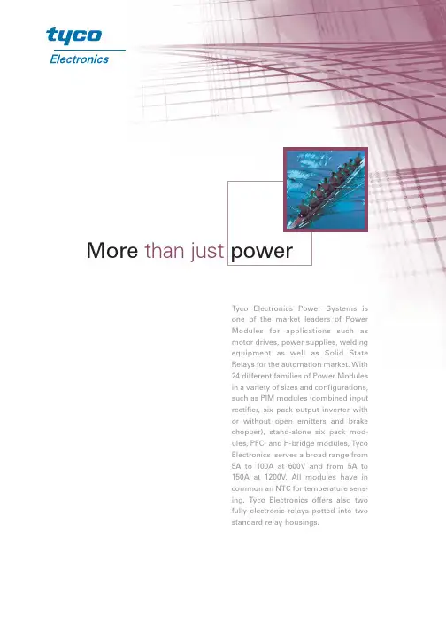
More than just powerTyco Electronics Power Systems isone of the market leaders of PowerModules for applications such asmotor drives, power supplies, weldingequipment as well as Solid StateRelays for the automation market. With24 different families of Power Modulesin a variety of sizes and configurations,such as PIM modules (combined inputrectifier, six pack output inverter withor without open emitters and b rakechopper), stand-alone six pack mod-ules, PFC- and H-bridge modules, TycoElectronics serves a broad range from5A to 100A at 600V and from 5A to150A at 1200V. All modules have incommon an NTC for temperature sens-ing. Tyco Electronics offers also twofully electronic relays potted into twostandard relay housings.level of integration, most suitable for low power frequency converters. Tyco Electronics Array PIMs are available in three different housings covering a power range from 5A to 70A at 600V and 5A to 75A at 1200V. All PIMs come with an input rectifier, an inverter six pack, a brake chopper and an NTC for temperature sensing. A striking attribute of Tyco Electronics smallest housing is its very fast and cost effective clip in assembly.Inverter Six Pack Modules suitable in particular for motion control applications are capable of handling currents up to 50A at 600V and 1200V. Their outstanding perfor-mance coupled with a low cost compact design is yet to be matched in the market.Inverter Half Bridge Modules are designed for motor control applications requiring currents up to 150A at 1200V. The small size together with the innovative flow through concept allows a very compact and easy to implement six pack arrangement meeting today’s and tomorrows demand.H-Bridge Modules for fast switching applications meet high requirements pertaining to component selection and package design. The usage of either MOSFETs with small R dson or the fastest IGBTs available, allows Tyco Electronics to offer a broad varietyof bridges for all kinds of switching modes (Hard Switching, Zero Voltage) to meet every need of the customer.Tyco Electronics offers stand alone PFC modules as well as its standard PIM modules with an integrated PFC. The stand-alone PFC modules are comprised of a half controlled input rectifier bridge limiting the inrush current and handling short circuits in the output. The built in low inductance capacitor allows to best short circuit high frequencies. PIM modules with integrated PFC come with an HF capacitor for best EMC performanceand ultra fast switching transistors and diodes for the PFC functionality.A d v a n t a g e sShunt ModulesIn particular for servo and vector drives where current sensing in the phases sometimes is required for monitoring the drive position and new technologies to even better serve its customers’ needs in the future.Application Note: IMC Driver BoardControl of 3~ asynchronous motor with U/F characteristics, where the micro controller integrated on the driver board via logic signals takes over the control of the high performance IGBT modules made by Tyco Electronics. With this device an economical system can be realized for the control of three phase systems.Available Module Packages:■flow 0, flow 1, flow 2, flat 1Advantages of Power Modules:■Integration of all active electronic power components ■High voltage isolation■Optimal mechanical and thermal interconnection ■Protection against environment ■Meet international standards (UL)■Compact module size ■Flow through concept ■Short gate connections761543289flow PIM ®2Part-N oV23990-P185-A10600V 50A V23990-P186-A10600V 75A V23990-P188-A101200V 25A V23990-P189-A101200V 35A V23990-P180-A101200V 50A V23990-P188-A201200V 35A V23990-P189-A201200V 50A V23990-P180-A201200V75Av o l t a g ec u r r e n t3533313451011896712flow PIM ®1Part-N oV23990-P81-A20600V 5A V23990-P82-A20600V 8A V23990-P83-A20600V 10A V23990-P84-A20600V 15A V23990-P85-A20600V 20A V23990-P86-A20600V 30A V23990-P89-A201200V 10A V23990-P80-A201200V 15A V23990-P481-A 600V 5A V23990-P482-A 600V 8A V23990-P483-A 600V 10A V23990-P484-A 600V 15A V23990-P485-A 600V 20A V23990-P486-A 600V 30A V23990-P487-A 1200V 10A V23990-P488-A 1200V 15A V23990-P480-A1200V25A v o l t a g e c u r r e n tflow PIM ®0Part-N oV23990-P541-A 600V 5A V23990-P542-A 600V 7A V23990-P543-A 600V 10A V23990-P544-A 600V 15A V23990-P545-A 600V 20A V23990-P549-A 1200V 10A V23990-P540-A1200V 15Av o l t a g ec u r r e n t0+EA l l m o d u l e s h a v e i n c o m m o n a n N T C f o r t e m p e r a t u r e s e n s i n g .flow PIM ®1+SPart-N oV23990-P321-A 600V 5A V23990-P322-A 600V 8A V23990-P323-A 600V 10A V23990-P324-A 600V 15A V23990-P325-A 600V 20A V23990-P329-A 1200V 10A V23990-P320-A1200V 15Av o l t a g ec u r r e n tflow PIM ®1+PPart-N oV23990-P303-B 600V 10A V23990-P304-B 600V 15A V23990-P305-B600V 20Av o l t a g ec u r r e n t576815 1613 1411 1216723458910 1112 1315 14flow PIM ®0+PPart-N oV23990-P371-B 600V 4A V23990-P372-B 600V 6A V23990-P370-B600V 10Av o l t a g ec u r r e n tPart-N oV23990-P381-A 600V 12A V23990-P382-A 600V 20A V23990-P380-A 600V 30A V23990-P380-D21600V 35A V23990-P385-A11600V 20A V23990-P386-A11600V 30A V23990-P387-A11600V40Ac u r r e nt1011flow PFC 0Part-N oV23990-P401-D01500V 2.5kW V23990-P401-D500V 4.5kWvo l t a gep o w e r 2111213876910141545V23990-P500-F01600V 35APart-N o : -FPart-N o: -F01fast PIM 1 Hv o l t a g e13876910141545PFC -IPMPart-N oV23990-P411-D230V 1.0kWI n p . v o l t -p o w e r 2Tyco ElectronicsPower SystemsRupert-Mayer-Strasse 4481359 Munich, Germany Tel.:+49 89 722-28457Fax.:+49 89 722-32936e-mail:power.switches@C o p y r i g h t © 2004, T y c o E l e c t r o n i c s , R a y c h e m G m b H , P o w e r S y s t e m s · P r i n t e d i n H u n g a r y · T E C .P S -023-1004.5-EHousing Dimensionsheight*: 17 mm width: 66mm depth: 32,5 mmheight*: 17,2 mm width: 82 mm depth: 37,4 mmheight*:17 mm width: 107,2 mm depth: 47 mmheight*:25 mm width: 80 mm depth: 70 mmThe information provided herein is believed to be reliable at press time. Tyco Electronics assumes no responsibility for inaccuracies or omis-sions. Tyco Electronics assumes no responsibility for the use of this information, and all such information shall be entirely at the users own risk.Prices and specifications are subject to change without notice. Tyco Electronics does not authorize or warrant any of its products for use in life-support devices and / or systems.flow PIM is a trademark of Tyco ElectronicsISO TS 16949 in Vorbereitungflow 0flow 1flow 2PFC-IPMTechnical data:W Up to 5 kW mechanical motor power (T h = 80°C, incl. 150% overload) W 3 phase Input RectifierW 3 phase IGBT Inverter + FRED with open emitter W Brake Chopper W UL-HousingW Clip In: The reliable interconnection between PCB and module W Alternative screw or clip mounting of heatsinkW Latest chip generation – trench field stop technologyC o p y r i g h t © 2005, T y c o E l e c t r o n i c s , R a y c h e m G m b H , P o w e r S y s t e m s · P r i n t e d i n H u n g a r y · T E C .P S -011-0805.2-Eflow 90PIM 1More and more of today's motor drive inverters require the heatsink to be in an up right position in respect to the PCB. For this kind of inverters Tyco Electronics introduces an innovative Power Module package with 90°mounting angle. This new package provides following benefits in addition to standard Power Module.Part-N ovoltage currentV23990-P631-A 600 V 6 A V23990-P632-A 600 V 10 A V23990-P633-A 600 V 15 A V23990-P634-A 600 V 20 A V23990-P635-A 600 V 30 A V23990-P639-A 1200 V 8 A V23990-P630-A1200 V 15 AThe information provided herein is believed to be re-liable at press time. Tyco Electronics,Power Systems assumes no responsibility for inaccuracies or omis-sions. Tyco Electronics, Power Systems assumes no responsibility for the use of this information, and all such information shall be entirely at the users own risk. Prices and specifications are subject to change without notice. Tyco Electronics, Power Systems does not authorize or warrant any of its products for use in life-support devices and / or systems.Tyco Electronics Power SystemsFinsinger Feld 185521 Ottobrunn, Germany Tel.: +49 (0)89 6089-830Fax: +49 (0)89 6089-833em.customerservice@Part-N ovoltage currentV23990-P441-C20600 V 6 A V23990-P443-C20600 V 10 A V23990-P444-C20600 V 15 A V23990-P445-C20600 V 20 A V23990-P446-C20600 V 30 A V23990-P449-C201200 V 8 A V23990-P440-C201200 V15 APart-N ovoltage currentV23990-P541-A20600 V 6 A V23990-P543-A20600 V 10 A V23990-P544-A20600 V 15 A V23990-P545-A20600 V 20 A V23990-P546-A20600 V 30 A V23990-P549-A201200 V 8 A V23990-P540-A201200 V15 AHousing dimensions:Height: 25.8 mm / Width: 114.8 mm / Depth: 64 mmT y c o E l e c t r o n i c s , R a y c h e m G m b H , P o w e r S y s t e m s · P r i n t e d i n H u n g a r y · T E C .P S -010-0805.2-EPart-N o V23990-P562-F 10 600 V 75 AV23990-P563-F 10 600 V 100 AV23990-P564-F 10 600 V 150 AV23990-P565-F 10 600 V 200 AV23990-P565-F 600 V 200 A *V23990-P567-F10 1200 V 50 A V23990-P568-F10 1200 V 75 A V23990-P569-F10 1200 V 100 A **V23990-P569-F 1200 V 100 A */*** V23990-P560-F 1200 V 150 A **Improved thermal resistance**Max 25 HP / 29.41 kW at 150% over load factor ***Max 45 HP / 29.41 kW at 150% over load factorThe information provided herein is believed to be re-liable at press time. Tyco Electronics,Power Systems assumes no responsibility for inaccuracies or omis-Part-N o voltage current V23990-P569-F20 1200 V 100 A*V23990-P569-F21 1200 V 100 A**V23990-P569-F30 1200 V 100 A***V23990-P569-F31 1200 V100 A****Part-N ovoltage current V23990-P623-F 600 V 60 A*V23990-P623-F01600 V 60 A**V23990-P623-F10600 V 60 A***V23990-P623-F11600 V60 A****W Clip In: The reliable interconnection between PCB, module and heatsink Part-N ovoltage current V23990-P590-J 1200 V 105 A V23990-P600-I 1200 V 105 A V23990-P590-J10 1200 V 78 A *V23990-P600-I101200 V 78 A *Tyco Electronics Power SystemsP590-J10P600-I10*optimized for ZVS**optimized for Hard Switching ***reduced Rth, optimized for ZVS****reduced Rth, optimized for Hard Switching*reduced Rth, without capacitor **reduced Rth, with capacitor ***without capacitor ****with capacitor* half controlled bridgeTechnical data:W 3 phase IGBT Inverter W Gate DriverW 3 phase current sensing W DC Bus-voltage sensing W Temperature sensorW Power supply for drive and control circuit W Save isolation of all logic signalsHousing dimensions:Height: 19.9 mm / Width: 98.7 mm / Depth: 97 mmT y c o E l e c t r o n i c s , R a y c h e m G m b H , P o w e r S y s t e m s · P r i n t e d i n H u n g a r y · T E C .P S -012-0805.2-Eflyer IPMThe information provided herein is believed to be re-liable at press time. Tyco Electronics,Power Systems assumes no responsibility for inaccuracies or omis-Integrated Power Block – combining a ceramic substrate with power dice and a PCB with drive and logic components on a common metal base plate. Part-N ovoltage current V23990-P520-A1200 V 25 AIso Vcc1Insulated VoltageAmplifierIso VccIso Vcc2Iso Vcc3DC-DCDC+DC–Insulated Gatedrive I s o V c cI s o V c c 1I s o V c cI s o V c c 2I s o V c cI s o V c c 3I s o V c cI s o V c c 1I s o V c c 2I s o V c c 3Sixpack + shunts on DBCInsulated Gatedrive Isolation Current Amplifier Insulated Gatedrive Insulated Gatedrive Insulated Gatedrive Insulated GatedriveIsolation Current AmplifierIsolation Current AmplifierNTC 1NTC 2DC S H U L U H VL V H W L W I U I V I WNTC OutputDC Link Sense 6 x PWMCurrent Sense OutputsSAFETY ISOLATIONU V WD C e x t .D C e x t .D C e x t .D C e x t .Tyco Electronics Power Systemspress on – screw down – readyMiniSKiiP ®II. 3 - PIMPart-N o V23990-K249-A SKiiP 35 NAB 126 V11200V 50A Picture 1V23990-K240-ASKiiP 36 NAB 126 V11200V70APicture 1SEMIKRON EquivalentVoltageCurrent Schematic The MiniSKiiP ®products provide solder less connection to the PCB enabling fast and easy mounting. With the 2nd generation the power levels per given footprint have been further increased. The MiniSKiiP ®series now covers a current range from 8 to 50A at 600V and 8 to 70A at 1200V in various configurations.MiniSKiiP ®I. 3 - PIMPart-N o V23990-K136-A SkiiP 31 NAB 063 600V 32A Picture 1V23990-K137-A SkiiP 32 NAB 063 600V 57A Picture 1V23990-K138-A SkiiP 30 NAB 12 1200V 22A Picture 1V23990-K139-A SkiiP 31 NAB 12 1200V 30A Picture 1V23990-K130-A SkiiP 32 NAB 12 120 V 45A Picture 1V23990-K187-C SKiiP 31 NAC 063 600V 35A Picture 2V23990-K188-C SKiiP 32 NAC 063 600V 50A Picture 2V23990-K189-C SKiiP 31 NAC 12 1200V 30A Picture 2V23990-K180-CSKiiP 32 NAC 121200V45APicture 2SEMIKRON Equivalent Voltage Current Schematic MiniSKiiP ®II. 1 - PIMPart-N oV23990-K209-A01SKiiP 11 NAB 126 V11200V 8A Picture 1V23990-K200-A01SKiiP 12 NAB 126 V11200V15APicture 1SEMIKRON EquivalentVoltageCurrent Schematic MiniSKiiP ®I. 1 - PIMPart-N o V23990-K108-A SkiiP 10 NAB 063 600V 8A Picture 1V23990-K109-ASkiiP 11 NAB 063600V 10A Picture 1V23990-K150-C10SKiiP 11 NAC 063 I600V12APicture 3with Option 2SEMIKRON Equivalent VoltageCurrent Schematic height*: 16 mm width: 82mm depth: 59 mmheight*: 16 mm width:82 mm depth: 59 mmheight*: 16 mm width:42 mm depth: 40 mmheight*: 16 mm width: 42 mm depth: 40 mmC o p y r i g h t © 2004, T y c o E l e c t r o n i c s , R a y c h e m G m b H , P o w e r S y s t e m s · P r i n t e d i n G e r m a n y · T E C .P S -024-1004.5-ETyco Electronics Power Systems The information provided herein is believed to be reliable at press time. Tyco Electronics assumes no responsibility for inaccuracies or omis-sions. Tyco Electronics assumes no responsibility for the use of this information, and all MiniSKiiP ®I. 2 - PIMPart-N oV23990-K127-A SkiiP 21 NAB 063 600V 19A Picture 1V23990-K127-A10SkiiP 21 NAB 063 600V 19A Picture 3 with Option 1,2,3V23990-K128-A SkiiP 22 NAB 063 600V 21A Picture 1V23990-K128-A10-600V 21A Picture 3 with Option 1,2,3V23990-K129-A SkiiP 20 NAB 121200V 11A Picture 1V23990-K129-A10SkiiP 20 NAB 12 1200V 11A Picture 3 with Option 1,2,3V23990-K120-A SkiiP 22 NAB 12 1200V 15A Picture 1V23990-K120-A10SkiiP 22 NAB 12 1200V 15A Picture 3 with Option 1,2,3V23990-K167-C10SKiiP 20 NAC 063 600V 15A Picture 3 with Option 3V23990-K168-C10SKiiP 22 NAC 063 600V 25A Picture 3 with Option 3V23990-K169-C10SKiiP 20 NAC 12 1200V 11A Picture 3 with Option 2,3V23990-K160-C10SKiiP 22 NAC 121200V15APicture 3 with Option 3Voltage Current Schematic MiniSKiiP ®II. 2 - PIMPart-N oV23990-K229-A01SKiiP 23 NAB 126 V11200V 25A Picture 1V23990-K220-A01SKiiP 24 NAB 126 V11200V35APicture 1SEMIKRON EquivalentVoltage Current Schematic Option 3Option 1Option 2Picture 1Picture 2Picture 3SEMIKRON Equivalent height*:16 mm width: 59 mm depth: 52 mmheight*:16 mm width: 59 mm depth: 42 mmC o p y r i g h t © 2004, T y c o E l e c t r o n i c s , R a y c h e m G m b H , P o w e r S y s t e m s · P r i n t e d i n G e r m a n y · T E C .P S -026-1004.5-ETyco Electronics Power Systems press on – screw down – readyThe MiniSKiiP ®products provide solder less connection to the PCB enabling fast and easy mounting. With the 2nd generation the power levels per given footprint have been further increased. The MiniSKiiP ®series now covers a current range from 8 to 50A at 600V and 8 to 70A at 1200V in various configurations.MiniSKiiP ®II. 2 - sixpackPart-N oV23990-K238-F SKiiP 24 AC 126 V11200V 35A V23990-K239-F SKiiP 25 AC 126 V11200V 50A V23990-K230-FSKiiP 26 AC 126 V11200V70ASEMIKRON Equivalent Voltage Current MiniSKiiP ®II. 1 - sixpackPart-N oV23990-K218-F SKiiP 11 AC 126 V11200V 8A V23990-K219-F SKiiP 12 AC 126 V11200V 15A V23990-K210-FSKiiP 13 AC 126 V11200V25ASEMIKRON Equivalent Voltage Current MiniSKiiP ®I. 1 - sixpackPart-N o V23990-K116-F-600V 25A V23990-K117-F -600V 45A V23990-K118-F SkiiP 23 AC 12 1200V 25A V23990-K119-F -1200V 30A V23990-K110-FSkiiP 25 AC 121200V40ASEMIKRON Equivalent Voltage Current height*:16 mm width: 59 mm depth: 52 mmheight*: 16 mm width: 42 mm depth: 40 mmheight*: 16 mm width: 42 mm depth: 40 mmThe information provided herein is believed to be reliable at press time. Tyco Electronics assumes no responsibility for inaccuracies or omis-sions. Tyco Electronics assumes no responsibility for the use of this information, and all *Height equals to installation height。
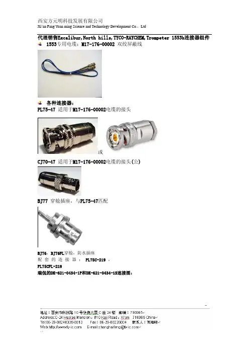
代理销售Excalibur,North hills,TYCO-RAYCHEM,Trompeter 1553b连接器组件 1553专用电缆:M17-176-00002 双绞屏蔽线各种连接器:PL75-47 适用于M17-176-00002电缆的接头或CJ70-47 适用于M17-176-00002电缆的接头(公)BJ77 穿舱插座,与PL75-47匹配BJ76,BJ76FL穿舱,防水插座配套的连接器:PL75C-219,PL75CFL-219瑞侃的DK-621-0434-1P和DK-621-0434-1S连接图:总线耦合器:单子线耦合器ESI-110双子线耦合器ESI-210三子线耦合器ESI-310四子线耦合器ESI-410五子线耦合器ESI-510六子线耦合器ESI-610八子线耦合器ESI-810ESI-610总线端接器 PNG1-4-78(RT500078)川贝特(ESI-P5078 EXCALIBUR)总线开关:ESI-R10、ESI-R11、ESI-R12、ESI-R20、ESI-R21、ESI-R22、ESI-R24、ESI-R27、ESI-R28、ESI-R60、ESI-R61ESI-R10常见的 连接适配器(Connectors/Adapter Mil-Std-1553):Cable Plug P/N: PL75Cable Jack P/N:CJ70Plug-to-Plug Adapter P/N: AD78Bulkhead Jack P/N: BJ770Bulkhead Jack P/N: BJ76Bulkhead Cable Jack P/N: BJ79Cable Plug (slide-on) P/N:PL73Tee P/N: BN73Cable Jack (threaded) P/N:CJ370Cable Plug P/N:PL375Dust Cap P/N:RT50000Dust Cap w/o Chain P/N: RT50000ncBulkhead Jack P/N:BJ157Cable PlugP/N:PL3155 (threaded)Cable Jack P/N:CJ150#8 Contact P/N: 8-90 (male) 8-91 (female)Terminator(78 ohms) P/N: RT500078Terminator (78 ohms) P/N: RT600078Terminator (78 ohms) P/N: RT700078Terminator (78 ohms) P/N: RT800078下图是相应的连接图:。
TE(泰科)连接器种类及型号TE(泰科)是全球连接和传感领域技术领军企业,2007年从Tyco International分离出来,并于纽约证券所挂牌上市,自此成了一家独立自主的公司。
2011年3月,Tyco Electronics 正式改名为TE Connectivity。
2017年财年,TE全球净销售额达131亿美元,合作的客户跨越150个国家,全球约有7,5000名员工。
目前,TE连接零部件年产量高达1200亿个,拥有(含申请中)的专利数量达1,4000个,主要授权分销商有Avnet、Arrow、Future、TTI、Waldom、Heilind、Premier Farnell等。
作为全球最大的连接器供应商,TE连接类产品种类繁多,主要包括:交流电源线路滤波器、光纤连接器、电源连接器、音频和视频连接器、火线连接器、射频互连、汽车连接器、排针和电线套管、太阳能和光伏连接器、背板连接器、I/O连接器、接线端子、板对板与夹层连接器、IC和元器件插座、端子、USB连接器、接线系统、卡边缘连接器、圆形连接器、照明连接器、D-Sub连接器、数据总线元器件、存储器连接器、模块化以太网连接器、FFC/FPC连接器、管脚和插座连接器等。
下面,小编整理了一份TE工业和车用电连接器选型指南,涵盖AMPSEAL、AMPSEAL16、CircularDIN、德驰、HDSCS、LEA VYSEAL等系列产品。
AEC系列该系列主要为汽车、公路和非公路辆、混合动力和电动汽车所提供的电气和电动互连产品,属于密封型重载电连接器,可使用16号德驰端子。
AMPSEAL系列AMPSEAL自动连接器具有极高的可靠性和较高的环境密封性,且易于使用。
该系列连接器具有电缆插头和PCB 安装集流排,可以经受发动机舱中的高温。
预安装的插座外壳连接器具有内嵌密封件,因此无需单个电线密封的锁环,同时一个完整的接口密封件可对插接连接器进行保护。
AMPSEAL 16 系列AMPSEAL 16 连接器专为非公路车辆、重载工业、休闲和农业应用而设计。
连接器有美国著名品牌Molex、TYCO(AMP)、3M、SAMTEC;日本著名品牌JST、HIROSE、YAZAKI、JAE;法国著名品牌FCI;韩国著名品牌KET、YEONHO、KUM等品牌。
接线端子座有德国PHOENIX、美国HEYCO、台湾DINKLE等品牌。
通过持续不断的努力,捷迈科技逐渐成为国内知名的连接器分销品牌。
捷迈科技分销的芯片品牌主要有TI(德州仪器)、ADI、NXP(恩智浦)、RAMTRON、XILINX、NATIONAL(国半)、ALTERA、ST(意法半导体)等。
其他电子元器件的主要产品线有:日本的NKK机电开关、OEG和P&G功率继电器、TAIKO汽车继电器、ROHM、NEC、Murata(村田)等品牌的电子元器件。
其中,日本著名机电开关品牌NKK是捷迈科技在中国区的授权分销品牌之一。
[ 日本Panasonic-松下电子部品 ] 松下麦克风、电容、轻触开关、超小型开关、编码器、中电流开关、微调开关、鼠标球、手机天线、手机按键开关、遥控器、控制器、绞轴开关、舵角传感器、汽车开关、感知开关)、电池保护器、透明触摸面板、货币机D等。
[ 美国Molex-莫仕连接器 ]莫仕成立于1938年专注于连接器行业,拥有10万多种性能可靠的产品。
基于遍布全球的资源、独特的创新技术和行业的专业知识,提供的产品和服务能够满足全球客户的不断增长的需求。
居于世界最大产品规模之列,包括电子、电气和光纤互连解决方案、开关和应用工具。
[ 美国Tyco/AMP-泰科/安普 ] 是世界上最大的无源电子组件制造商,并在先进的无线、光纤类和全功率系统产品及技术方面处于全球领先地位,同时还提供布线产品及整体系统。
[ 日本JST-日本压着端子 ] 日本圧着端子制造株式会社,简称 JST,又名杰世腾。
成立于 1957 年,是日本第一家生产和销售无焊端子的制造公司,专注于接线端子和连接器。
[ 日本Hirose-广濑 ] 广濑电机株式会社创建于1937年,总部设在日本东京。
Fiber Optic Splice Closure Trays: A and B SizeI N S T A L L A T I O N I N S T R U C T I O NFor FOSC 400 or 450 A and B, AIR FOSC and FTerm AF Splice Closures1. General Product InformationImportant: Read and follow all safety precautions and warnings documented in the appropriate closure installation instructions.The A and B size trays are standard spice trays designed for use in Tyco Electronics’FOSC ber optic splice closures and related products.1.1 A Tray DetailsFOSC A trays are designed for use in FOSC 400 A, FOSC 450 A, FOSC 450 BS, AIRFOSC and FTERM AF closures and related products. Trays are typically equipped with splice modules to accommodate a variety of splice types, and have a maximum capaci-ty (see matrix below) of 24 single ber splices and 144 mass fusion bers (12 ber rib-bon x 12 splices).Note for ribbon applications: A ribbon tray (FOSC-ACC-A/B-TRAY-12-RBN) is also available to accommodate ribbon splicing and storage on the same tray.1.2 B Tray DetailsFOSC B trays are designed for use in FOSC 400 B, FOSC 450 B and Air FOSC closures and related products. Trays are typically equipped with splice modules to accommo-date a variety of splice types, and have a maximum capacity (see matrix below) of 24single ber splices and 144 mass fusion bers (12 ber ribbon x 12 splices). Note for ribbon applications, a ribbon tray (FOSC-ACC-A/B-TRAY-12-RBN) is also available to accommodate ribbon splicing and ribbon storage on the same tray.2. Kit ComponentsEach FOSC A or B splice tray kit consists of: •Splice tray with cover . Tray routing tabs•Appropriate type/quantity of splice modules3.2Tray Kit Information3.Installation in FOSC 400 A, FOSC 400 B,FOSC 450 A, FOSC 450 B, andFOSC 450 BS Splice ClosuresNote: The BS (B-Short) closure uses A type trays.Note: It is recommended to use SM6 or SM8 for 900 micron splicing, due to the tray slack storage capacity.3.1“Butt” Splice Configuration1.Install hinge in tray by inserting one hinge pin into thetray. Twist the hinge slightly to pop the other pin into thetray.2.Install the hinged tray into the tray holder bracket of theclosure. (Figure 1)e a pen to mark each tube 1/4” beyond the tie downslot. Use a buffer tube cutter to cut each tube at the markand remove the excess tube from each group.Note: Wrap buffer tubes with LBT wrap before tie wrap-ping to tray.4.Cut the fibers to be spliced so that they are 24 - 42” inlength. The 900 micron fibers may need to be cut closerto the lower end of this range due to the tray storagecapacity.5.Splice two fibers and store the splice sleeve in the splicemodule.Note: Refer to Figure 5 for correct fiber routing, and some examples of incorrect fiber routing.7.Gather slack fiber to be stored at one end of the tray. Foldthe fiber loops over on themselves to form a coil roughlythree inches in diameter. Lay the coil on the tray aroundthe arcs. Fibers must be routed as shown in Figures 2and 3.8.SM12: Route fibers 1-6 to one end of the tray, and routefibers 7-12 to the far end of the tray as shown in Figure 3. Note: Maintain minimum 30 mm bend radius (2-3/8”diameter).9.SM24: If splicing 24 fibers using SM12 splice modules,route fibers 1-12 to one end of the tray and fibers 13-23to the other end of the tray.Note: If a “tray crossover” is needed, refer to Figure 5. Use the center section of the tray to reverse the direction in which the fibers are stored.10.Install tray tabs to help contain fibers. (Figure 4)11.Cover each splice tray with its protective plastic cover.12.Coil and place uncut loose buffer tubes in the storage“sock” or basket provided with the closure kit. Hold thetrays together and secure the sock to the bottom of thetrays with the Velcro* fastener strap provided with theclosure kit.* Velcro is a trademark of Velcro Industries.Hot-melt adhesive©2006, 2007, 2016 CommScope Inc. All Rights Reserved PML FY3925 F149.05/07The information given herein, including drawings, illustrations and schematics which are intended for illustration purposes only, is believed to be reliable. However, CommScope makes no war-ranties as to its accuracy or completeness and disclaims any liability in connection with its use. CommScope’s obligations shall only be as set forth in CommScope’s Standard Terms and Conditions of Sale for this product and in no case will CommScope be liable for any incidental, indirect or consequential damages arising out of the sale, resale, use or misuse of the product. Users of CommScope products should make their own evaluation to determine the suitability of each such product for the speci c application.Technical Assistance Center (TAC)Tel.: 800.830.5056Email:**************************。
430Dimensions are shown forreference purposes only.Dimensions are in inches over(millimeters) unless otherwisespecified.Specifications and availabilitysubject to change.Technical support:Refer to inside back cover. Features•10 amp switching capacity.•UL Class F (155°C) coil insulation system standard.•1 Form A and 1 Form C contact arrangements.•Ideal for domestic appliances, HVAC and security.•Resists high temperature and various chemical solutions.• Immersion cleanable, plastic sealed case available.Coil Data @ 20°CVoltage: 3 to 48VDC.Nominal Power:450 milliwatts.660 milliwatts for 48VDC coil.Coil Temperature Rise: 35C° max, at rated coil voltage.Max. Coil Power: 130% of nominal.Duty Cycle: Continuous.T73 seriesLow Profile, 10 AmpPrinted CircuitBoard RelayMechanical DataTermination: Printed circuit terminals.Enclosure (94V-0 Flammability Ratings):Weight: 0.42 oz. (12g).File E29244File LR48471Initial Insulation ResistanceBetween Mutually Insulated Elements:108 ohms min. @ 500VDC.Ag contact rating.Initial Dielectric StrengthBetween Open Contacts:750VAC 50/60 Hz. (1 minute).Between Coil and Contacts: 2,000VAC 50/60 Hz. (1 minute).Operate Data @ 20°COperate Time: 10 ms (excluding bounce).Release Time: 5 ms (excluding bounce).Environmental DataTemperature Range:Storage: -40°C to +130°C.Operating: -30°C to +80°C.Vibration, Mechanical: 10 to 55 Hz., 1.5mm double amplitudeOperational: 10 to 55 Hz., 1.5mm double amplitude.Shock, Mechanical: 100g min.Operational: 10g min.Operating Humidity:45 to 85% RH.Contact Data @ 20°CArrangements: 1 Form A (SPST-NO) and 1 Form C (SPDT).Material:Silver-cadmium oxide.Max. Switching Rate: 240 ops./min. (no load).30 ops./min. (rated load).Expected Mechanical Life: 10 million operations.Expected Electrical Life:100,000 operations.Minimum Load: 10mA @ 5VDCInitial Contact Resistance: 100 milliohms max. @ 100mA, 6VDC.Contact Ratings @ 20°C with relay properly vented. Remove ventConsult factory for other ratings.Figure 1 - Coil Temperature Rise Operate Time Life Expectancy0.20.30.40.50.60.70.80.20.30.40.50.60.70.8Coil Power (W)Coil Power (W)605040302010Temp.Rise(Deg.)1002Contact Current (A)Operation(x14)10146Note: Graphical data should not be used as a substitute for specific application verification. To be used for estimates only.Users should thoroughly review the technical data before selecting a product partnumber. It is recommended that user also seek out the pertinent approvals files ofthe agencies/laboratories and review them to ensure the product meets therequirements for a given application.431Dimensions are shown for reference purposes only.Dimensions are in inches over (millimeters) unless otherwise specified.Specifications and availability subject to change. Technical support:Refer to inside back cover.。
2007年8月1日Tyco Electronics (Dongguan) Ltd4. 铜合金与可分离弹片设计目录•4.1 弹片端子的要求•4.2 金属的机械性能•4.3 合金的制造过程•4.4 铜合金结构和硬化技术•4.5 通用铜合金和材料性能•4.6 正向力选择•4.7 梁的属性•4.8 梁的设计•4.9 可加工性设计•4.10 插入机构•4. 11梁的设计举例4.1 弹片接触的要求接触弹片要实现的功能:-传送电源或者传播信号.-提供正应力,建立和维持接触界面.-适应连接器系统的制造公差.接触弹片材料必须是:-导电的-有好的弹性-充分的可成形性便于制造.导电率导电率要求对信号接触弹片不非常需要.更高的数值是必需的针对电源连接器,接触弹片原料必须满足机械要求. 特别,机械强度和可成形性之间的折中决定,在多数铜合金中的哪个是连接器工业有益的在.4.2. 金属的机械属性应力-应变曲线可伸展的应力,弯曲应力.-弹性模量-2% 屈服应力(力)-屈服应变-可伸展或者极限应力-拉长对于连接器,特别重要的是应力松弛和硬度.-应力松弛:是重要的对连接器,因为它导致正应力损失. -硬度:抗变形性-导电性: 是关键的,在设计电源端子.-热导系数: 是关键的,在设计电源端子.4.3.合金制造过程A铸造片和条的制造由基本的铸造操作开始.在每个粒中, 存在规则的晶格,然而颗粒方向相对于另外的是任意的. 颗粒间的交叉部分,晶粒周围,是不规则的区域B. 热轨热轨提供铸造晶粒结构的初始分类和减少原料厚度.热轨优势:•热轨温度下不加工硬化,大大地减少厚度•再结晶过程减小和均匀晶粒结构.控制一致的条厚度和宽度是重要的,厚度的变化多样在随后的冷轧和退火操作不容易被消除.简言之,热轨:-减少厚度.-减小颗粒尺寸.-由于高的温度和随后的再结晶,颗粒保持任意的和未失真的.C. 冷轧冷轧功能使热轧后的条到最后的标准厚度和需要的机械属性.•取向性晶粒结构向轧方向拉长.保持结构,不发生再结晶,导致在材料属性平行的和垂直的起向性到轧制方向.影响:拉力和柔软性,可成形性.有时根据比率R/t表达,R是没有破裂弯曲的半径和t是厚度GOOD WAY AND BAD WAY弯曲定义R/t明显增加屈服强度.冷轧完成2件事:-最终地减少厚度-冷作材料(拉长颗粒)和变硬到需要韧度D.退火退火是冷轧过程的中间级,当条被带到接近最后的标准规格, 排除加工硬化,允许冷轧进一步减少厚度.原子和颗粒结构重新整理.减少加工硬化的内应力.E. 切割最后步骤,切开条到一定宽度,用于冲压和成型模. 切割应力导致类似的弓和弧形4.4.铜合金结构和硬化技术金属性能:规则的原子结构和缺陷造就金属的机械性能.自由电子存在原子结构中. 这些自由电子负责金属的导电率.热导系数,亦包括原子结构的影响,特别是晶格振动,特别在合金中.在金属中有原子的排列和晶体结构( lattice).BCC结构:组成由每个角落的原子和附加的在中心的原子. 一些BCC结构金属是铬,钨和磁铁. FCC 结构:也是由每个角落的原子和附加在立方体每个面中心的原子.铜,镍,银,黄金和微克(无磁性的铁)是有FCC结构的金属.有3个主要的加固,或者硬化,机械结构在金属中. 他们是:-加工硬化: 加工硬化应用到全金属和合金由于它依靠结晶缺陷.-固熔体加固: 固熔体加强依赖额外的合金元素和在原子晶格中应变影响. 固熔体加强发生在所有合金,至于变化度数依赖相关的合金要素大小和化学性能.-第二相加固: 第二相加强仅仅发生在多元相存在合金系统,由于合金要素溶度的化学和尺寸影响.• A.加工硬化:当工作或者机械变形时材料变硬了•有用的主要缺陷是位置错乱,当额外原子平面插入在规则的晶体结构,通过破坏晶体的规律性, 和地方化应变区域,位置错乱妨碍滑倒过程,这结果是材料发生局部"坚固".•加工硬化仅仅是针对纯原料的强化机理,诸如铜.•加工硬化的加强能力是有限的,和伴随不受欢迎的减弱柔软性和可成形性.冷轧减低厚度时加工硬化材料性能•冷轧韧度ASTMB 601冷轧百分率:参照在最后的退火之后条厚度的减少量. 冷轧百分率决定工作硬化量.B. 固熔体变硬•液态,溶质(溶解物)是合金元素,溶于溶剂铜. 这差别发生在固态中,有2类型固熔体, 替换的和空隙的.•替换溶体•空隙溶体•固溶体合金强化机理是合金元素进入主晶格的扭曲和应变引起硬化.C. 第二相加固•第二相加强当第二相被引入到晶体结构. 硬化起因于格子组织被扰乱. 既然这样,扰乱发生由于第二相有不同的结构相比父母晶体.•淀积[脱溶]硬化是主要的第二相加固针对使用于连接器铜合金. 铍-铜( BeCu)是传统的第二相合金使用于连接器.•尺寸和金属间的分布的是关键的. 理想,均匀地分发许多的小的金属互化物,结果格子组织被破裂和应变产生更硬的材料.ASTM B6014.5.一般铜合金和材料属性A. UNS定义铜合金B. 铜和高度铜合金( C 1 XXXX )•铜: 至小含铜量99.3%个的金属. 电解质的强硬的程度( ETP )和氧自由高导电率( OFHC )铜例子被使用在Tyco电子.•高铜合金:含铜量少于99.3%大于96%的合金,铍铜合金(CI7 XXX),C 19500和C 19400是例子C. 黄铜•黄铜,铜合金包含锌当做主要的合金要素和或者没有其他的元素. 锻造合金包含3主要的黄铜: 铜-锌, 铜-铅-锌(铅黄铜)和铜-锡-锌(锡黄铜).弹壳黄铜三七黄铜(70/30铜/锌) 黄铜最常用在Tyco电子•UNS指定黄铜是C 2 XXXX,铅黄铜C 3 XXXX和锡黄铜C 4 XXXX. UNS指定弹壳黄铜是C 26000.D.青铜•概括地说,青铜在铜合金主要的合金元素是非锌或者镍的合金. 起初青铜是铜-锡合金, 针对精炼的合金主要的青铜家族是: 铜-锡-磷(磷bronze),铜-锡-铅-磷(铅磷bronze),铜-铝(铝青铜)和铜-矽(矽青铜).•磷青铜有UNS指定C 5 XXXX. C 51100通常是Tyco电子最常用的磷青铜.•铅磷青铜被使用于螺旋压机应用.•铝青铜有UNS指定C 6 XXXX. 合金C 68800, Tyco电子某些使用铜-锌-铝合金.•矽青铜是也在C 6 XXXX系列.E. 铜镍•镍当做主要的合金元素和或者没有另外元素.强调的属性是机械强度度,可成形性,应力松弛和导电率.•F. 黄铜-占优势的黄铜合金在Tyco电子在弹壳黄铜,70/30铜锌,•C 26000个是最普遍的端子材料,低的费用,有限的强度, 减少可成形性和强度,和贫乏的应力松弛抵抗,限制它的应用范围.•铅黄铜也被使用于螺旋压机应用,•G. 磷青铜-磷青铜是铜-锡合金,磷的不影响合金的机械属性但是必须控制在导电率消极效果. 3等级磷青铜被使用,C 51000,C 51100和C 52100,和C 51100个占优势的合金.磷青铜是最全能的合金,由于它的好综合属性.磷青铜合金增加锡机械属性随而增长. 这肯定的特性减少可成形性又导电率.•H. 铍铜合金-当做“保险”材料. 机械和应力松弛特征是高黄铜3-10倍. 关于铍的环境影响,采用之前,应该得到顾客和国家的同意.2个供应商,BrushWellman和NGK Metal.•I. 铜硅镍-在连接器企业,铜硅镍( CuSiNi)最近成为普遍的. 它被看当做较低的费用替代针对高导电率BeCu( C 17510和C 17410个)和没有环境的关系, C 70250优于磷青铜的应力松弛抵抗和更高导电率使它成为候选针对更高电流应用.•J. 纯铜-应用纯铜在连接和接线片.铜当作可分离的触点组件使用,它一般被"助手"弹性支持. "助手"弹性经常是不銹钢•K. 高铜-3高铜合金使用在Tyco电子,C 15100,C 19400, 和C 19500.C 15100是锆青铜合金,能适应有限强度的弹性尺寸的电源端子的候选,和高的导电率的优点. C 15100有较好的应力松弛抵抗比铜但是坏的导电率.C 19400可以考虑用于与时间/温度寿命有关的电源端子.L. 应力松弛•金属弹性有应力时, 随着时间的过去,反作用力将逐渐地减少,这是由于材料应力松驰.减少比率是温度与金属合金的函数. 不同普遍的弹片合金在不同的温度有不同的习性.•当定义了材料允许使用的最高温度限度,保持至少60 -70%的原始应力通常是需要的,即保持60 -70%的端子正应力.4.6.选择正应力•正应力影响特征:•-摩擦/配合力•-磨损•-在端子上的应力•-在连接器HOUSING上的应力•-接触电阻•-接触分界面稳定性•连接器必须有的"最适宜的"或者"最小的"正应力•10克的正应力是充分的产生3毫欧的接触电阻,足够任何信号应用. 这"金属的"或者贵金属最小的力, 然而,没有计算膜瓦解/移位力. 针对连接器"最小的"正应力是100克,4.7.横梁习性A 梁弯曲•假如挠矩导致弹性形变应力会线性地变更,零在中间的平面,最大限度压应力在顶面和相应的拉应力在底面. 在充分的挠矩引起塑性变形,横梁中心会保持有弹性,而是近表面的层有plastically应力,有压缩力在上面和拉伸在底部. 当挠矩移动到弹性核心会提供回复力,这将尝试回归到横梁的最初的平坦结构. 顶面现在是在拉伸和底受压, 这相对的应变状态的倾向结构.B 弹性范围,工作范围,和力范围•弹性范围是应用在横梁上的没有永久变形的变位度. 换言之,释放端子会回到原始外形.•工作范围被定义做当横梁正应力超出最小的正当的偏斜范围变化•力范围是相对工作范围的正应力变化.•C. 塑性变形量•假如横梁位移超过它的弹性范围,当负荷被释放它不回到原始外形,变化的数量叫塑性变形量D 剩余冲模影响•端子在冲模中定形需要材料的塑性(无弹性的)变形,产生残余应力分布,类似于横梁被弯曲超过弹性范围,这些残余应力影响已定型的端子随后的弹性范围.剩余应力在正确方向. 相反,Figure4.20.B) 剩余应力在不正确方向•获得正确的残余应力分发,端子定形超过需要数量和反向定形到最后的外形. 这增加更多的冲模工位,而且放置残余应力在有利的方向.•4.8.横梁设计A.公差掌握•端子横梁必须适应连接器的制造变化. 这些变化包括下列,而不有限于这些:•-PIN几何公差.•-插座几何公差.•-PIN和插座之间排列(这是HOUSING公差和装配公差的总数).•-材料习性的变化.B. 公差降低分析•应用在相对普通的连接器中和很少的配合要求(<<100). 假如端子有多的配合要求, 推荐考虑完全弹性接触.•C. 最大化弹性范围•实质上所有接触弹片设计, 需要提高弹性范围和随后的工作范围,2个影响因素是材料属性和弹片几何尺寸.•选择材料需要考虑的是:•-它会遭受的热环境(应力松弛)•-材料定形能力( R/T )•-费用•-载流要求(电导性)•-弹性习性(弹性模量,屈服应力)•通常影响横梁的弹性范围的2个几何因子是长度和高度.•较大的横梁更有弹性,,他们消耗更多的材料和占据更多的空间.截面逐渐变细的梁也改进弹性范围.D.端子仿真和设计•有限元分析( FEA )•Tyco:ANSYS和MECHANICA4.9.可制造性设计当设计接触簧片,需考虑冲模冲压能力. 冲模工程师与产品设计师配合工作.A.剪切-从板材移除材料.轮廓比率:t/W•这比率能被分类.•-轮廓比率> 2 (容易的)•-2 > 轮廓比率> 1 (更难)•-轮廓比率< 1 (极端的难)•硬原料是较好的针对狭窄轮廓,他们好分开.B. 定形-弯曲成形.•半径/厚( R/T )比率引用在冲模的定形工位的弯曲半径和坯料厚度. 材料都有R/T最小限制. 材料越硬,越有更高的比率,阻止材料破裂.一般说来:•-硬材料是最好针对狭窄的剪切(低轮廓比率)和最大化横梁的弹性成绩. •-软材料是最好针对需要充实定形的端子.•-当成形操作复杂性增加,冲模速度减慢.•-剪切处的紧凑的轮廓半径,增加毛刺.C. 冲模公差•剪切比定形尺寸更精确. 联贯步骤越多,变化越多.例子:•-冲模的一步冲压能制造出最精确的特征. “剪切后”尺寸通常能在+/-0.03毫米或者更小.•-盒型端子,需要剪切和多重弯曲的,通常有间隙尺公差+/-0.05毫米或者更大.4.10.插入机构有3要素勾画出曲线的外形:•-弹片习性,包括弹性和满的正应力•-摩擦系数•-PIN和端子的导角无摩擦•PIN和端子的导角确定顶点外形. 导角越大,峰值越窄,因为梁必须在短距离分开,结果,峰值一定大。