HPSSL激光切割头 中文介绍
- 格式:pdf
- 大小:475.09 KB
- 文档页数:13

激光切割机软件使用说明 (图文笔记版)一、总体功能概述⑴操作软件的三大版块:图一、ByVision主菜单操作界面。
图二、HANDLING-OPERATION操作界面图三、LaserView操作界面⑵控制按键的两个部分:图一、操控手柄。
急停按钮:当出现紧急状况的时候按下,整个系统,包括激光发生器等都会停止。
顺时针转松后用Reset键复位。
停止按钮:在不同的时候,有停止、取消、中断等不同的定义,只有在旁边的红灯亮时会起作用。
(而不亮时也可代表中止)微调按钮:常用于“原点偏移”时手动移动激光头。
方法是在手动模式下(TOOL灯应该是亮的)按住“JOG”再按一下“X+”或“Y+”此时“X+”或“Y+”旁边的灯亮,再来旋转微调旋钮。
“X+”代表X轴方向移动,“Y+”代表Y轴方向移动。
微调旋钮用于精调轴的位移,手动定位用TOOL功能:通常为开,这时只要按下“Z—”激光头就会直接下降到最低位置;而当关闭时激光头时,可以上下移动到任何位置,移动时要非常小心,因为有可能激光头会撞到钢板上。
三维方向控制按键。
特殊功能键:通常只有喷气作用(常用来检测切割气体气压)(喷气的类型与压力由“参数来确定”),当点中屏幕上的特殊功能按钮时,它就有喷油、吹压缩空气、切割脉冲方式、Z轴校正的作用。
脉冲按键:用来测试焦点位置时在胶带上打口时用。
光闸按键:用来手动切割。
方法降下Z轴,按住此键,然后再移动X、Y轴进行切割。
图二、屏幕右侧按键。
急停按钮:用途同上。
复位按键:一但有急停后该灯会灭。
必须使用它来复位,和电柜側键的功能是一样的。
开门按键:按下会闪,可以开门,门关上后常亮,门没关上时是灭的。
停止自动操作如自动交换工作台释放切割头二、激光切割机每个版块的具体功能介绍⑴ByVision(用户名:CH 密码:1)①“MAIN(F5)”主菜单:其中包括“管理员”、“视图”、“诊断”、“清屏”、“信息”、“关闭”。
“管理员”、“视图”:已设置好,一般无需改动。
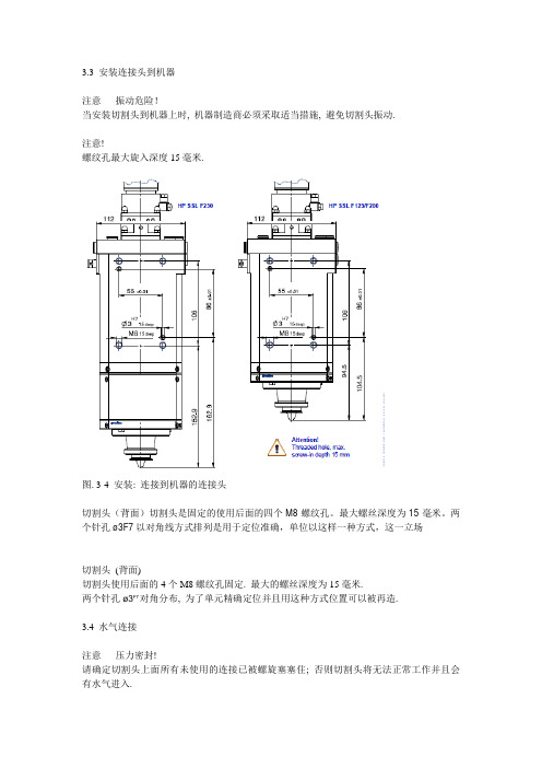
3.3 安装连接头到机器注意– 振动危险!当安装切割头到机器上时, 机器制造商必须采取适当措施, 避免切割头振动.注意!螺纹孔最大旋入深度15毫米.图. 3-4 安装: 连接到机器的连接头切割头(背面)切割头是固定的使用后面的四个M8螺纹孔。
最大螺丝深度为15毫米。
两个针孔ø3F7以对角线方式排列是用于定位准确,单位以这样一种方式,这一立场切割头(背面)切割头使用后面的4个M8螺纹孔固定. 最大的螺丝深度为15毫米.两个针孔ø3F7对角分布, 为了单元精确定位并且用这种方式位置可以被再造.3.4 水气连接注意– 压力密封!请确定切割头上面所有未使用的连接已被螺旋塞塞住; 否则切割头将无法正常工作并且会有水气进入.3.4.1 连接切割气体图. 3-5 安装: 切割气体1 切割气体连接G1/82 切割气体连接G1/8切割气体注意– 切割气体!只能使用干净, 干燥的气体.对切割头的最大压力为25bar (2.5 MPa).连接切割气体(连接1, 2) (G1/8).普雷茨特推荐使用尽可能最大直径的水管连接两个切割气体连接.未使用的连接必须用螺旋塞塞住.交货时, 连接已用假塞子塞上.注意: 如果顶部的两个切割气体连接已经使用, 切割气体的水管必须始终连接到两个连接.3.4.2 连接冷却气体图. 3-6 安装: 喷嘴电极冷却气体3 冷却气体连接G1/8, 喷嘴4 辅助气体/液体, G1/87 4的出口连接(4)(G1/8)与相关的出口孔(7) (ø8 毫米)可以用来为工作区提供额外的气体和液体. 最大压力为5bar (0.5 MPa).未使用的连接必须使用螺旋塞塞住.喷嘴电极冷却气体(可选)冷却喷嘴电极如果需要, 螺母的冷却气体出口可以提供额外的喷嘴电极冷却.我们推荐您在切割强反射和厚板材的时候使用额外的气体喷嘴冷却设备.注意– 冷却气体!冷却喷嘴的最大压力位5bar (0.5 MPa).只能使用压缩气体或者具有如下特征的气体(无氧):* 水含量: 无需考虑* 油含量: 最大每立方米1毫克* 颗粒尺寸: 最大4微米将气体供给水管连接到连接(3) (G1/8).注意: 未使用的连接必须使用螺丝塞子塞住.冷却气体压力冷却气体流量和压力主要取决于用于切割的激光能量.因此我们无法推荐一个合适气压数值. 但是, 正确的压力数值可以通过测试得到.最佳的冷却效果在大约0.5 bar (0.05 MPa) 下就已经可以达到.3.4.3 连接水冷系统注意– 水冷!* 只能使用去离子/蒸馏水, 导电率< 20μS/cm (见页5-42的”水冷回路的腐蚀” ).* 水冷回路的温度的设置需要保证不会形成光学上的凝结(见露点, 页7-64上面的表7-2). * 最大水压为5 bar (0.5 MPa).必须保证最小水冷流量为2.0 I/min.*应使用外径/内径为ø6/ ø4 毫米的供水线.图. 3-7 安装: 水冷(水冷回路)8 水连接G1/8, 供给水管9水连接G1/8, 回流水管将水冷水管连接到相关连接(G1/8).供给水管连接到连接(8), 回流水管连接到连接(9) (见媒介连接标签, 页2-14上面的图. 2-4).注意– 水冷回路的腐蚀!为了避免仪器被腐蚀, 必须按照机器制造商的指导间隔进行维护, 必须关注激光源制造商或者冷却单元制造商.为了保护水冷回路(不锈钢)不受电化学腐蚀, 不能使用铜或者黄铜连接, 只能使用不锈钢或者塑料连接.3.5 连接系统电子设备当安装电缆时必须遵守下面的基本规则:* 当线性驱动器移动时:- 插件连接器不能受到任何压力.- 电缆不能擦碰其他部件.* 电缆不能弯曲到最小弯曲半径以下.* 电缆不能受到任何牵引应力.切割头使用Lasermatic分析电子系统工作分析电子系统图. 3-8 安装: 连接图(分析电子系统)1 5针连接器(6, 标签) 3 5针电缆, 检测装置2 BNC连接(5, 标签) 4 传感器电缆(最大20米)Switch 开关Focal length 焦距[mm]SW1 SW2 SW31 1 1 011F125F200F250BU BK BN WH Wire colours (optional) 线缆颜色(可选)备注:SW1可用的替换检测盒SW2与SW3聚焦码(F125 - F250)SW4可用的防护窗表3-1 检测装置– 开关分配连接5针电缆(检测装置)1.旋转5针角度使其与连接(1)耦合.2.连接开放式电缆的端头到机器的PLC.操作时请记录电缆应该在何处运行.连接图请见页7-61上面的图. 7-1.备注: SW1 可用的替换墨盒; SW4 可用的保护窗盒连接传感器电缆连接传感器电缆(2)至BNC耦合(1), 固定并且连接到分析电子系统.操作时请记录传感器电缆的最大长度.关于分析电子线路图的详细信息请参阅独立的操作说明文档”冲孔传感器PS130” (P0130-0000-BEN10)注意– 电缆!损坏的电缆和插件连接器会引起线性驱动器失控的移动从而影响切割结果.不要将传感器电缆与其他的更大直径的移动电缆捆绑在一起.否则, 当电缆线弯曲的时候会产生牵引应力损坏电缆.4 调试4.1 安全事项一般安全事项我们认为您已经知道并且注意到了下列普遍接受的安全规则:* VDE规则,特别是VDE 0100/0837* BGV A1 一般规则* BGV A3 电气系统与设备* BGV B2 激光辐射事件防护规则个人需求任何修理和检修工作需要专业知识并且只可以由经过训练的专业人员实施。


普瑞玛激光切割机说明书普瑞玛激光切割机可加工范围3000*1500毫米,最大定位速度每分钟140米,最大钣材中了800公斤,发生器功率2500W,3000W,及4000W,最大加速度6G所谓激光切割就是将激光束照射到工件表面时释放的能量来使工件融化并蒸发,以达到切割和雕刻的目的,具有精度高,切割快速,不局限于切割图案限制,自动排版节省材料,切口平滑,加工成本低等特点,讲逐渐改进或取代于传统的切割工艺设备。
激光源一般用晶体或二氧化碳激光束,所需要的功率也不是很大,一般在几十瓦到几百瓦左右只和普通的家用电器的功率差不多,一般在切割的时候还配备有告诉风冷或水冷设备,能是工件在加工的时候更加的稳定.意大利普瑞玛激光切割机主要由六个部件组成:机架,光路系统(激光机),电路,工作平台,水路,操作软件。
普瑞玛激光切割机原理激光是一种光,与自然界其电发光一样,是由原子(分子或离子筝)跃迁产生的,而且是自发辐射引起勺。
激光虽然是光,但它与普通光明显不同是激光仅在最初极短的时间内依赖于自发辐射,此后的过程完全由激辐射决定,因此激光具有非常纯正的颜色,几乎无发散的方向性,雕刻机,极高的发光强度。
激光同时又具有高相干性、高强度性、高方向性,激光通过激光器产生后由反射镜传递并通过聚集镜照射到加工物品上,使加工物品(表面)受到强大的热能而温度急剧增加,使该点因高温而迅速的融化或者汽化,配合激光头的运行轨迹从而达到加工的目的。
激光加工技术在广告行业的应用主要分为:激光切割、激光雕刻两种工作方式,对于每一种工作方式,我们在操作流程中有一些不尽相同的地方。
激光雕刻:主要是在物体的表面进行,分为位图雕刻和矢量雕刻两种:位图雕里将我们所需要雕刻的图形进行挂网处理并转化为单刻:我们先在PHOTOSHOP色BMP格式,而后在专用的激光雕刻切割软件中打开该图形文件。
根据我们所加工的材料我们进行合适的参数设置就可以了,而后点击运行,激光雕刻机就会根据图形文件产生的点阵效果进行雕刻。

红外波段激光驱动极紫外光刻光源研究进展目录一、内容概括 (2)二、红外波段激光技术概述 (3)1. 红外波段激光原理及特点 (4)2. 红外波段激光技术的发展现状 (5)三、极紫外光刻光源技术 (6)1. 极紫外光刻光源原理 (7)2. 极紫外光刻光源技术分类 (7)3. 极紫外光刻光源技术的发展趋势 (9)四、红外波段激光驱动极紫外光刻光源的研究进展 (10)1. 研究现状 (11)2. 技术难点及挑战 (12)3. 国内外研究动态对比 (13)五、红外波段激光驱动极紫外光刻光源的应用前景 (14)1. 在集成电路制造领域的应用前景 (16)2. 在其他相关领域的应用前景 (17)六、实验研究与分析 (18)1. 实验设计 (19)2. 实验过程与数据记录 (20)3. 实验结果分析 (21)七、结论与展望 (22)1. 研究结论 (23)2. 研究不足与展望 (24)一、内容概括本篇论文综述了红外波段激光驱动极紫外光刻光源的研究进展,重点介绍了近年来在该领域取得的重要突破和研究成果。
在光刻技术中,极紫外光(EUV)光刻因其高分辨率和优异工艺性能成为了关键的技术手段。
EUV光的产生需要高功率的激光作为驱动源,且目前现有的激光器技术在能量转换效率和稳定性方面仍存在不足。
红外波段激光作为EUV光的驱动源成为了研究的热点。
红外波段激光具有波长长、能量低、易于控制等优点,能够提供足够的光强和稳定性以满足EUV光刻的需求。
研究人员通过改进红外波段激光器的结构、采用新的工作物质和优化激光参数等方式,提高了激光的能量转换效率和稳定性。
红外波段激光驱动的EUV光刻光源还在集成电路制造、微纳加工等领域展现出广泛的应用前景。
随着技术的不断进步和应用需求的不断提高,未来红外波段激光驱动极紫外光刻光源的研究将更加深入和广泛。
红外波段激光驱动极紫外光刻光源的研究取得了显著的进展,但仍面临诸多挑战和问题。
未来需要在提高能量转换效率、稳定性和输出功率等方面进行深入研究,以推动光刻技术的进一步发展。
德国PRECITEC普雷斯特HP2CO2切割头产品手册Precitec KG ? Version 04/2007P0593-0000-BEN10HP2" cutting headLasermatic ?Cutting head for CO 2 lasersOperating instructionsII ? Precitec KG ? Version 04/2007P0593-0000-BEN10Imprint HP2"This documentation is protected by copyright law for Precitec KG and must not be reproduced without the prior written consent of Precitec KG or used against the due interest of Precitec KG. It is exclusively for internal use for service work. Any other use is not permitted. Any communication of this documentation to a third party requires the prior express written permission of Precitec KG.We reserve the right to change technical details in the descriptions, information and illustrations in this documentation.This product group is protected by the patents below:Printed in the Federal Republic of Germany.Responsible for the content Translation of the original instructions Precitec KG Draisstra?e 1 D - 76571 Gaggenau - Bad Rotenfels Tel.:+49 (0)7225/ 684-0 Fax:+49 (0)7225/ 684-900 eMail:******************************************** 403DE129507189JP2563705US5,489,888US5,702,622Summary of changesDate Chapter/page Subject, change, measure03/2002Chapter 4.5Setting the focal position09/2004--New edition03/2005--Revision cooling circuit corrosion08/2006--Revision, Lasermatic04/2007--Revision, technical dataP0593-0000-BEN10? Precitec KG ? Version 04/2007IIINotes HP2"NotesIV? Precitec KG ? Version 04/2007P0593-0000-BEN10P0593-0000-BEN10? Precitec KG ? Version 04/2007VTable of contents1 Basic safety notes 1-11.1 Warranty and liability 1-11.2 Meaning of symbols and notes 1-11.3 Designated use 1-31.4 Basic standards 1-31.5 Obligations of operator and personnel 1-41.6 Normal operation safety measures 1-41.6.1 Protection against electric shock 1-41.6.2 Grounding the system 1-41.6.3 Risk of injury from moving parts 1-51.6.4 Risk of injury from explosion 1-51.6.5 Risk of injury from toxic dust 1-51.6.6 Risk of injury from laser radiation 1-51.6.7 Cooling circuit corrosion 1-61.6.8 Noise occurring during the laser cutting process 1-61.7 Storage and transport 1-61.8 What to do in emergency situations 1-62 Product description 2-72.1 Overall view 2-72.1.1 Design and functions 2-82.1.2 Distance control 2-102.1.3 Protective equipment 2-102.2 Technical Data 2-112.3 Mechanical dimensions 2-122.4 Media connections 2-132.5 Specific versions - Exchangeable cartridge with cartridge frame 2-142.6 Specific versions - Compact cartridge 2-162.7 Accessories and special tools 2-182.7.1 Graticule (adjustment aid)2-182.7.2 Additional tactile electrode2-182.7.3 PS130 piercing sensor 2-192.7.4 Collision protection cage 2-213 Installation 3-233.1 Safety notes 3-233.2 Checking the parts supplied 3-243.3 Fitting the cutting head 3-263.4 Inserting the lens into the exchangeable cartridge with cartridge frame 3-273.4.1 Exchangeable cartridge with F5" lens (? 2")3-283.4.2 7.5" exchangeable cartridge with F7.5" lens (? 2")3-293.4.3 Fitting the exchangeable cartridge with cartridge frame 3-30Table of contents HP2"3.5 Inserting the lens into the compact cartridge3-313.5.1 5"/ 7.5" compact cartridge with F5" lens (? 2")3-323.5.2 5"/ 7.5" compact cartridge with F7.5" lens (? 2")3-343.5.3 Fitting the compact cartridge3-363.6 Fitting the sensor insert, ceramic part and nozzle electrode3-373.7 Fitting the cutting head to the machine3-383.8 Connecting gas and water3-393.8.1 Fitting the water and gas connections3-393.8.2 Connecting the cutting gas3-403.8.3 Connecting the focusing lens cooling gas3-403.8.4 Connecting the nozzle electrode cooling gas3-403.8.5 Connecting the cooling water system3-413.9 Connecting to power3-434 Commissioning4-45notes4-454.1 Safety4.2 Checking the laser beam position4-464.3 Adjusting the focusing lens4-474.3.1 Centring the lens4-474.3.2 Setting the focal position4-485 Maintenance5-515.1 Safetynotes5-51summary5-525.2 Maintenancetasksrecommendations5-535.3 Maintenancewornparts5-545.4 Replacing5.4.1 Replacing the insulating plate, sensor insert gasket5-545.4.2 Replacing the nozzle electrode5-565.5 Cleaning or replacing the focusing lens5-565.6 Maintaining the gaskets and sealing rings (exchang. cartridge)5-575.6.1 Cutting head with exchangeable cartridge and cartridge frame5-575.6.2 Cutting head with compact cartridge5-586 Erroranalysis6-59notes6-596.1 Safety6.2 Malfunctions6-607 Appendix7-637.1 ConversionUnits7-63of7.2 Parts and special equipment available7-637.3 Lens ring sets for lens fitting7-66VI? Precitec KG ? Version 04/2007P0593-0000-BEN10List of illustrationsFig. 2-1Cutting head, overall view2-7Fig. 2-2Mechanical dimensions2-12Fig. 2-3Cutting head - Connections, overview2-13Fig. 2-4Cutting head - Accessories and special equipment2-14Fig. 2-5Cutting head - Accessoriesand special equipment (compact cartridge)2-16Fig. 2-6WH 1145 graticule2-18Fig. 2-7Additional tactile electrode2-18Fig. 2-8Piercing sensor - Cutting head with adapter, sensors2-19Fig. 2-9Piercing sensor - Adapter, connection dimensions2-20Fig. 2-10Piercing sensors - Fixing the sensors2-20Fig. 2-11ZM HP KLS collision protection cage2-21Fig. 3-1Cutting head - Exploded view3-26Fig. 3-25" exchangeable cartridge - Fitting the lens3-28Fig. 3-37.5" exchangeable cartridge - Fitting the lens3-29Fig. 3-4Fitting - Cartridge frame, exchangeable cartridge3-30Fig. 3-55"/ 7.5" compact cartridge - Fitting example of an F5" lens3-32Fig. 3-65"/ 7.5" compact cartridge - Fitting an F5" lens3-33 Fig. 3-75"/ 7.5" compact cartridge - Fitting example of an F7.5" lens3-34Fig. 3-85"/ 7.5" compact cartridge - Fitting an F7.5" lens3-35 Fig. 3-9Fitting - Compact cartridge3-36Fig. 3-10Fitting – Sensor insert and nozzle electrode3-37Fig. 3-11Fitting dimensions - Cutting head, back3-38Fig. 3-12Fitting - Water and gas connections3-39Fig. 3-13Fitting - Pre-amplifier (HP2" cutting head only)3-43 Fig. 4-1Fitting the graticule4-46Fig. 4-2Exchangeable cartridge - Location of the adjustment elements4-47Fig. 4-3Exchangeable cartridge - Adjustment button, viewing window4-48Fig. 5-1Maintenance recommendations5-53Fig. 5-2Maintenance - Insulating plate,sensor insert and nozzle electrode5-54Fig. 5-3Maintenance - Sensor insert sealing ring5-55Fig. 5-4Maintenance - Gasket, sealing ring (exchangeable cartridge)5-57Fig. 5-5Maintenance - Gasket, sealing ring (compact cartridge)5-58P0593-0000-BEN10? Precitec KG ? Version 04/2007VIIList of tables HP2"List of tablesTable 2-1Technical Data2-11Table 3-1Tool summary, cutting head3-25Table 3-2Gasket and sealing ring summary, cutting head3-25 Table 3-3Auxiliary tools for lenses and lens mounts3-27Table 3-4Auxiliary tools for lenses and lens mounts3-31Table 6-1Error analysis - Summary of mechanical malfunctions6-61Table 7-1Parts and special equipment available7-65Table 7-2Lens ring sets7-66VIII? Precitec KG ? Version 04/2007P0593-0000-BEN10P0593-0000-BEN10? Precitec KG ? Version 04/20071-11 Basic safety notesThese operating instructions contain the most important notes for operatingthe product in compliance with safety regulations.1.1Warranty and liabilityThe General Conditions for the Supply of Products and Services in theElectrical and Electronics Industry and the amendments and restrictions ofPrec itec KG’s General Terms of Delivery apply to our products.We reserve the right to modify designs to improve quality or extend the fieldsof use and to make modifications for manufacturing reasons.If the unit is operated incorrectly or if processes are carried out wrongly,reflections can be caused when laser cutting highly reflective materials suchas copper, brass or aluminium that would damage the cutting head and othersystem components.We do not assume any liability for damages or injuries that are caused byimproper handling or programming as described above.Dismantling the unit may result in warranty claims becoming null and void.However, this does not apply to the replacement of parts thatare subject tonormal wear and tear and require maintenance or setup work, unlessexpressly stated otherwise in this documentation.We cannot accept liability if unauthorised modifications are made to the cutting head.1.2Meaning of symbols and notesIn these operating instructions the following designations and symbols areused to indicate hazardous situations and for notes.Observe all instructions and guidelines in this documentation.In addition, accident prevention regulations and instructions applicable to thearea of use must be observed.Warning!This symbol indicates an imminent or potential danger to the life and health ofindividuals. Not observing these notes may result in severe effects on healthor life-threatening injuries.1Basic safety notes HP2"1-2? Precitec KG ? Version 04/2007P0593-0000-BEN10P0593-0000-BEN10? Precitec KG ? Version 04/20071-31.3Designated useThe HP2" cutting head has been designed for integration into a lasermachine. It is used for cutting metals with CO 2 lasers.Only use the cutting head in dry working environments. The cutting headmust only be operated in compliance with the specifications stated in theTechnical Data sheet.Electromagneticcompatibility (EMC)The HP2" cutting head complies with the EN 61000-6-4 and EN 61000-6-2 standards as specified in Directives No. 89/336/EEC and 92/31/EEC whenused as a standalone unit or in combination with the relevant units describedin this document. It is intended for industrial use.It is possible that these standards may not be met when using units or cablesprovided by the client. Therefore, always use original equipment andreplacement parts and observe the notes contained in the accompanyingmanuals relating to an EMC-compliant installation.If the cutting head is integrated into a system and operated together withother units, the whole system must comply with the above directives so that ageneral operating permit can be granted.1.4Basic standardsBelow you will find a summary of basic German and international standardsand regulations that apply to Precitec products. Precitec does not guaranteethat this summary is complete.DIN VDE 0100Regulations for setting up power current installations with rated voltages up to 1000V DIN EN 207Personal eye protection: Filters and eye protectors against laser radiation (laser goggles)DIN EN 292-1 and 2Safety of machines:Basic terms, general design guidelines;Part 1: Basic terminology, methodologyPart 2: Technical guidelines and specificationsDIN EN 60204-1Safety of machines:Electrical equipment for machines. Part 1: General requirements (VDE 0113-1; IEC 6024-1: 1997, amended)DIN EN 60825-1Safety of laser equipment: Part 1; 2003-10 (VDE 0837, IEC 60825-1)DIN EN 61000-6-4Electromagnetic compatibility (EMC):Basic standard on interference emission, Part 2: Industry Any use different from the designated use is regarded as non-compliant. Inthis case liability rests with the user.1Basic safety notes HP2" DIN EN 61000-6-2Electromagnetic compatibility (EMC):Basic standard on interference immunity, Part 2: IndustryBGV A3Accident prevention regulation: Electrical systems and equipmentBGV B2Accident prevention regulation: Laser radiation1.5Obligations of operator and personnelThe operator of the machine is obliged to ensure that the personnel workingat the machineare familiar with the basic safety at work and accident preventionregulations and have been instructed on how to operate the machinehave read and understood the safety notes contained in these operatinginstructions and have confirmed this with their signature.Personnel must be instructed according to the regulations and safety notesand informed of potentially hazardous situations.Manufacturer’s and supplier’s regulations must be observed. The prescribedprotective equipment must be used.1.6Normal operation safety measuresIf it has been decided that it is no longer possible to operate the unit ormachine safely, it must be switched off. The unit or the machine must beprotected against unintended use.1.6.1Protection against electric shockWhen installing the unit, make sure that the electrical equipment is designedin such a way that individuals are protected against electric shock.The regulations contained in EN60204-1, especially those included inSections 6 'Protection against electric shock' and 6.4 'Protection by PELV'(Protective Extra Low Voltage) must be met.Recommendation Use a safety isolating transformer complying with EN61588-2.1.6.2Grounding the systemMake sure the system is earthed according to regulations.The cutting head does not have an earth connection.1-4? Precitec KG ? Version 04/2007P0593-0000-BEN10P0593-0000-BEN10? Precitec KG ? Version 04/20071-51.6.3Risk of injury from moving partsWhen lowering the linear drive to which the cutting head is fitted, there is arisk of injury or damage to equipment.Never put your hands or other parts of the body under the cutting head.Repair or maintenance work must only be carried out with the power supplyswitched off.1.6.4Risk of injury from explosionAccording to their designated use, cutting heads are loaded with gas underpressure. The specified maximum pressure must never be exceeded. Toensure that individuals are not harmed, the cutting head must always be keptin perfect condition.Any connecting elements such as screws and nuts must be tightened firmly. Ifthe focusing lens is broken, the additional notes contained inChapter 1.6.5 must be observed.1.6.5Risk of injury from toxic dustGenerally, ZnSe focusing lenses are used with CO 2 laser cutting heads.Zinc selenide, if present as dust or a vapour, is highly toxic. These lenses areinserted into the relevant cutting head’s lens mount.They are not an integral part of the cutting head.If the lens breaks, the unit must be cleaned and the lens disposed of properly.Please note the lens supplier’s instructions.1.6.6Risk of injury from laser radiationThe cutting head does not emit any laser radiation. However, laser radiationis guided through the cutting head. The laser machine must be switched offwhen carrying out any installation or maintenance work.During commissioning the laser machine may operate in risk class 4:Avoid radiation to eyes or skin caused by direct or scattered radiation.Do not look directly at the laser beam, not even using optical instruments.Use laser goggles complying with DIN EN 207 and BGV B2.1Basic safety notes HP2"1.6.7Cooling circuit corrosionTo avoid any corrosion the instructions and prescribed maintenance intervalsof the machine manufacturer, laser source manufacturer or cooling unitmanufacturer must be observed.The cutting head is fitted with pure stainless steel cooling circuits.To protect the cooling circuits against electro-chemical corrosion copper orbrass connections must not be used. Only stainless steel connections can beused.If the water circuit includes stainless steel, aluminium and copper parts,special measures must be taken to prevent corrosion on the aluminium parts,see paragraph …Machine corrosion inhibitor” on page3-41 from Nalco.1.6.8Noise occurring during the laser cutting processWith high cutting gas pressure the noise level is > 75dB(A). Noise emitted bythe cutting gas depends on the operating conditions. To ensure thatindividuals are not harmed by noise, the manufacturer of the machine mustimplement or provide written information on relevant safety measures.1.7Storage and transportTo prevent damaging the unit during storage or transport the following basicrules must be observed:Keep the storage temperature within the range specified in the TechnicalData sheet.Adopt suitable measures to avoid damage due to humidity, vibration orimpact.Do not store the unit within or in the vicinity of magnetic fields (e.g.permanent magnet or strong alternating field).1.8What to do in emergency situationsDisconnect the machine from the power supply; set the main switch toAUS ('OFF').Only use Class B extinguishers to extinguish fires.1-6? Precitec KG ? Version 04/2007P0593-0000-BEN10P0593-0000-BEN10? Precitec KG ? Version 04/20072-72 Product description2.1Overall viewFig. 2-1Cutting head, overall view1Cutting head 6Viewing window 2Media connections (lateral, left)7Exchangeable cartridge 3 Media connections (lateral, right)8Sensor insert 4Pre-amplifier 9Ceramic part 5Optical unit adjustment button 10Nozzle electrode2Product description HP2"2.1.1Design and functionsThe HP2" cutting head is used for distance controlled cutting of thin and thickgauge metal sheets using CO2 lasers on flat bed systems. Itis preciselyworked, rugged, service-friendly and can be adjusted easily.The cutting head includes capacitive distance sensors that constantly recordthe standoff distance between the nozzle electrode (cutting nozzle) and theworkpiece. The system’s electronic unit analyses the sensor signal that isused to control a linear drive.Focusing lens The cutting head is able to accept 2" diameter lenses (?1.5" on request).Focusing lenses with F5", F7.5" and F10" focal lengths can be used. The clearaperture is a max. 45.5mm.The focusing lens is located in a pressure-resistant exchangeable cartridgewhich can be removed from the cutting head by undoing two quick fasteningnuts.The focusing lens adjustment devices are integrated into the exchangeablecartridge. Two Allen (socket) head screws on the front of the exchangeablecartridge are used to centre the lens.Exchangeable cartridge with cartridge frame (individual focal lengths)The adjustment range is ±1.5mm. The focusing position is set using a large rotating button with 0.05 mm divisions.The axial adjustment range is:-10 ... +10mm for the 5" focal length and-18 …+10 mm for the 7.5" focal length.Compact cartridge (dual focal lengths)The adjustment range is ±1.5mm. The focusing position is set using a large rotating button with 0.05 mm divisions.The axial adjustment range is:-18 ... +10mm for the 5"/ 7.5" focal lengthsThe focusing lens can be removed from the exchangeable cartridge from below. To do this, only the face nut that fixes the lens in the lens mount must be undone using the auxiliary tool. The lens mount does not have to be removed for this. However, it can be unscrewed using the focal position adjustment device so that the lens is easily accessible for fitting and removal. When inserting the exchangeable cartridge it can be positioned precisely between two brackets on the cartridge frame Therefore there is no need for readjustment. This also applies when fitting exchangeable cartridges with different focal lengths. In this case the cartridge frame must be replaced too as the design of both parts is different depending on the focal length used. Here, the exchangeable cartridge and the cartridge frame can be removed directly from the cutting head. T o do this, only two quick fastening nuts on the cartridge frame must be undone. The cartridge frame can also be positioned precisely. Focal lengths can thus be changed without having to spend a long time on conversion.2-8? Precitec KG ? Version 04/2007P0593-0000-BEN10P0593-0000-BEN10? Precitec KG ? Version 04/20072-9Cutting gasThe cutting head can be operated at a cutting gas pressure of up to 25bar (2.5MPa). It has two cutting gas connections that can be used as required. The connection that is not used must beclosed using a screw plug. All connections (G1/8) are located at the top of the cutting head.Sensor insertThe sensor insert is fitted firmly to the cutting head. With the protective plate removed, it can be removed by undoing four fastening screws. The protective plate prevents any short circuit in the integral sensor electronic unit caused by spatters.At the back of the sensor insert there is an M5 threaded hole that is connected to the internal cutting gas channels. This connection can be used to bleed the unit quickly when changing the cutting gas.Ceramic partA ceramic part is fitted to the sensor insert from below. It locks into place firmly as it can only be fitted in one direction. It is secured by a union nut.Nozzle electrodeThe nozzle electrode is screwed into the ceramic part and can be replaced easily if worn. Precitec nozzle electrodes and ceramic parts are very precisely worked. Because of the minimum concentricity tolerance any re-adjustment work can be reduced or avoided when replacing these parts.The DE HP and DE HP CON nozzle electrodes have different diameters and cylindrical nozzle hole depths. Because of the smaller diameter/depth ratio, the DE HP CON type has advantages when cutting with low pressure. The DE HP type enables a larger focal position adjustment range and is therefore more suitable for high pressure inert gas cutting.Fitting thecutting head to thelinear Z driveFour M 8 threaded holes (15mm long) on the back of the cutting head are used for fixing and two pin holes ?3F7 (15mm long) enable a precise fitting. T o centre the cutting head relative to the beam guidance tube there is a recess with an internal pressfit at the top (for fitting dimensions please refer to Fig.3-11 on page 3-38).Cutting non-metalsUsing additional tactile electrodes (see Chapter 2.7.2 on page 2-18) distance-controlled cutting of non-metals is also possible.Please refer to Chapter 7.2 on page 7-63 for the nozzle electrode diameters that can be supplied.2Product description HP2"2-10? Precitec KG ? Version 04/2007P0593-0000-BEN10P0593-0000-BEN10? Precitec KG ? Version 04/20072-112.2Technical DataTable 2-1Technical Data Cutting head HP2"Focal length 5"; 7.5"Lens diameter2";1.5" on request Adjustment range:–horizontal–verticalExchangeable cartridge with cartridge frame - 5" focal length - 7.5" focal lengthCompact cartridge - 5"/ 7.5" focal lengths ± 1.5 mm-10 ... +10 mm -18 ... +10 mm-18 ... +10 mmClear aperture (with ?2" lenses)max. 45.5 mm Installation–Threaded holes, lateral–Pin holes, lateral–Laser tube centring, recess with external fit–Fastening holes for additional parts4 x M8, 15mm long 2 x ?3F7, 15 mm long ?64f7, 4 mm long 4 x M4, 10 mm long, ?76 mm Media connections–Cutting gas (2x)–Lens air cooling–Nozzle electrode cooling/ protective gas–Water cooling, inlet and outletG1/8, max. 25 bar G1/8, max. 5 bar G1/8, max. 5 bar G1/8, max. 7 bar Water cooling circuitStainless steel System electronic unit connectionLasermatic ? via pre-amplifier (external fitting), BNC Operating temperatureStorage temperatureHumidity5 ... 55 °C -25...+55° C (+70° C for a short time)30 % to 95%, no dew Length, axialAxial length from the nozzle tip to the connectionhead’s upper edge (standard configuration).241.1 mmWeightapprox. 5.1 kg。
© Precitec KG • Version 04/2007P0593-0000-BEN10HP2" cutting headLasermatic ®Cutting head for CO 2 lasersOperating instructionsII © Precitec KG • Version 04/2007P0593-0000-BEN10Imprint HP2"This documentation is protected by copyright law for Precitec KG and must not be reproduced without the prior written consent of Precitec KG or used against the due interest of Precitec KG. It is exclusively for internal use for service work. Any other use is not permitted. Any communication of this documentation to a third party requires the prior express written permission of Precitec KG.We reserve the right to change technical details in the descriptions, information and illustrations in this documentation.This product group is protected by the patents below:Printed in the Federal Republic of Germany.Responsible for the content Translation of the original instructions Precitec KG Draisstraße 1 D - 76571 Gaggenau - Bad Rotenfels Tel.:+49 (0)7225/ 684-0 Fax:+49 (0)7225/ 684-900 eMail:precitec@precitec.de DE92 09 561 DE93 11 281 DE40 35 403DE129507189JP2563705US5,489,888US5,702,622Summary of changesDate Chapter/page Subject, change, measure03/2002Chapter 4.5Setting the focal position09/2004--New edition03/2005--Revision cooling circuit corrosion08/2006--Revision, Lasermatic04/2007--Revision, technical dataP0593-0000-BEN10© Precitec KG • Version 04/2007IIINotes HP2"NotesIV© Precitec KG • Version 04/2007P0593-0000-BEN10P0593-0000-BEN10© Precitec KG • Version 04/2007VTable of contents1 Basic safety notes 1-11.1 Warranty and liability 1-11.2 Meaning of symbols and notes 1-11.3 Designated use 1-31.4 Basic standards 1-31.5 Obligations of operator and personnel 1-41.6 Normal operation safety measures 1-41.6.1 Protection against electric shock 1-41.6.2 Grounding the system 1-41.6.3 Risk of injury from moving parts 1-51.6.4 Risk of injury from explosion 1-51.6.5 Risk of injury from toxic dust 1-51.6.6 Risk of injury from laser radiation 1-51.6.7 Cooling circuit corrosion 1-61.6.8 Noise occurring during the laser cutting process 1-61.7 Storage and transport 1-61.8 What to do in emergency situations 1-62 Product description 2-72.1 Overall view 2-72.1.1 Design and functions 2-82.1.2 Distance control 2-102.1.3 Protective equipment 2-102.2 Technical Data 2-112.3 Mechanical dimensions 2-122.4 Media connections 2-132.5 Specific versions - Exchangeable cartridge with cartridge frame 2-142.6 Specific versions - Compact cartridge 2-162.7 Accessories and special tools 2-182.7.1 Graticule (adjustment aid)2-182.7.2 Additional tactile electrode 2-182.7.3 PS130 piercing sensor 2-192.7.4 Collision protection cage 2-213 Installation 3-233.1 Safety notes 3-233.2 Checking the parts supplied 3-243.3 Fitting the cutting head 3-263.4 Inserting the lens into the exchangeable cartridge with cartridge frame 3-273.4.1 Exchangeable cartridge with F5" lens (Ø 2")3-283.4.2 7.5" exchangeable cartridge with F7.5" lens (Ø 2")3-293.4.3 Fitting the exchangeable cartridge with cartridge frame 3-30Table of contents HP2"3.5 Inserting the lens into the compact cartridge3-313.5.1 5"/ 7.5" compact cartridge with F5" lens (Ø 2")3-323.5.2 5"/ 7.5" compact cartridge with F7.5" lens (Ø 2")3-343.5.3 Fitting the compact cartridge3-363.6 Fitting the sensor insert, ceramic part and nozzle electrode3-373.7 Fitting the cutting head to the machine3-383.8 Connecting gas and water3-393.8.1 Fitting the water and gas connections3-393.8.2 Connecting the cutting gas3-403.8.3 Connecting the focusing lens cooling gas3-403.8.4 Connecting the nozzle electrode cooling gas3-403.8.5 Connecting the cooling water system3-413.9 Connecting to power3-434 Commissioning4-45notes4-454.1 Safety4.2 Checking the laser beam position4-464.3 Adjusting the focusing lens4-474.3.1 Centring the lens4-474.3.2 Setting the focal position4-485 Maintenance5-515.1 Safetynotes5-51summary5-525.2 Maintenancetasksrecommendations5-535.3 Maintenancewornparts5-545.4 Replacing5.4.1 Replacing the insulating plate, sensor insert gasket5-545.4.2 Replacing the nozzle electrode5-565.5 Cleaning or replacing the focusing lens5-565.6 Maintaining the gaskets and sealing rings (exchang. cartridge)5-575.6.1 Cutting head with exchangeable cartridge and cartridge frame5-575.6.2 Cutting head with compact cartridge5-586 Erroranalysis6-59notes6-596.1 Safety6.2 Malfunctions6-607 Appendix7-637.1 ConversionUnits7-63of7.2 Parts and special equipment available7-637.3 Lens ring sets for lens fitting7-66VI© Precitec KG • Version 04/2007P0593-0000-BEN10List of illustrationsFig. 2-1Cutting head, overall view2-7Fig. 2-2Mechanical dimensions2-12Fig. 2-3Cutting head - Connections, overview2-13Fig. 2-4Cutting head - Accessories and special equipment2-14Fig. 2-5Cutting head - Accessoriesand special equipment (compact cartridge)2-16Fig. 2-6WH 1145 graticule2-18Fig. 2-7Additional tactile electrode2-18Fig. 2-8Piercing sensor - Cutting head with adapter, sensors2-19Fig. 2-9Piercing sensor - Adapter, connection dimensions2-20Fig. 2-10Piercing sensors - Fixing the sensors2-20Fig. 2-11ZM HP KLS collision protection cage2-21Fig. 3-1Cutting head - Exploded view3-26Fig. 3-25" exchangeable cartridge - Fitting the lens3-28Fig. 3-37.5" exchangeable cartridge - Fitting the lens3-29Fig. 3-4Fitting - Cartridge frame, exchangeable cartridge3-30Fig. 3-55"/ 7.5" compact cartridge - Fitting example of an F5" lens3-32Fig. 3-65"/ 7.5" compact cartridge - Fitting an F5" lens3-33Fig. 3-75"/ 7.5" compact cartridge - Fitting example of an F7.5" lens3-34Fig. 3-85"/ 7.5" compact cartridge - Fitting an F7.5" lens3-35Fig. 3-9Fitting - Compact cartridge3-36Fig. 3-10Fitting – Sensor insert and nozzle electrode3-37Fig. 3-11Fitting dimensions - Cutting head, back3-38Fig. 3-12Fitting - Water and gas connections3-39Fig. 3-13Fitting - Pre-amplifier (HP2" cutting head only)3-43Fig. 4-1Fitting the graticule4-46Fig. 4-2Exchangeable cartridge - Location of the adjustment elements4-47Fig. 4-3Exchangeable cartridge - Adjustment button, viewing window4-48Fig. 5-1Maintenance recommendations5-53Fig. 5-2Maintenance - Insulating plate,sensor insert and nozzle electrode5-54Fig. 5-3Maintenance - Sensor insert sealing ring5-55Fig. 5-4Maintenance - Gasket, sealing ring (exchangeable cartridge)5-57Fig. 5-5Maintenance - Gasket, sealing ring (compact cartridge)5-58P0593-0000-BEN10© Precitec KG • Version 04/2007VIIList of tables HP2"List of tablesTable 2-1Technical Data2-11Table 3-1Tool summary, cutting head3-25Table 3-2Gasket and sealing ring summary, cutting head3-25Table 3-3Auxiliary tools for lenses and lens mounts3-27Table 3-4Auxiliary tools for lenses and lens mounts3-31Table 6-1Error analysis - Summary of mechanical malfunctions6-61Table 7-1Parts and special equipment available7-65Table 7-2Lens ring sets7-66VIII© Precitec KG • Version 04/2007P0593-0000-BEN10P0593-0000-BEN10© Precitec KG • Version 04/20071-11 Basic safety notesThese operating instructions contain the most important notes for operating the product in compliance with safety regulations.1.1Warranty and liabilityThe General Conditions for the Supply of Products and Services in the Electrical and Electronics Industry and the amendments and restrictions of Precitec KG’s General Terms of Delivery apply to our products.We reserve the right to modify designs to improve quality or extend the fields of use and to make modifications for manufacturing reasons.If the unit is operated incorrectly or if processes are carried out wrongly, reflections can be caused when laser cutting highly reflective materials such as copper, brass or aluminium that would damage the cutting head and other system components.We do not assume any liability for damages or injuries that are caused by improper handling or programming as described above.Dismantling the unit may result in warranty claims becoming null and void. However, this does not apply to the replacement of parts that are subject to normal wear and tear and require maintenance or setup work, unless expressly stated otherwise in this documentation.We cannot accept liability if unauthorised modifications are made to the cutting head.1.2Meaning of symbols and notesIn these operating instructions the following designations and symbols are used to indicate hazardous situations and for notes.Observe all instructions and guidelines in this documentation.In addition, accident prevention regulations and instructions applicable to thearea of use must be observed.Warning!This symbol indicates an imminent or potential danger to the life and health of individuals. Not observing these notes may result in severe effects on health or life-threatening injuries.1Basic safety notes HP2"1-2© Precitec KG • Version 04/2007P0593-0000-BEN101.3Designated useThe HP2" cutting head has been designed for integration into a lasermachine. It is used for cutting metals with CO 2 lasers.Only use the cutting head in dry working environments. The cutting headmust only be operated in compliance with the specifications stated in theTechnical Data sheet.Electromagneticcompatibility (EMC)The HP2" cutting head complies with the EN 61000-6-4 and EN 61000-6-2 standards as specified in Directives No. 89/336/EEC and 92/31/EEC whenused as a standalone unit or in combination with the relevant units describedin this document. It is intended for industrial use.It is possible that these standards may not be met when using units or cablesprovided by the client. Therefore, always use original equipment andreplacement parts and observe the notes contained in the accompanyingmanuals relating to an EMC-compliant installation.If the cutting head is integrated into a system and operated together withother units, the whole system must comply with the above directives so that ageneral operating permit can be granted.1.4Basic standardsBelow you will find a summary of basic German and international standardsand regulations that apply to Precitec products. Precitec does not guaranteethat this summary is complete.DIN VDE 0100Regulations for setting up power current installations with rated voltages up to 1000V DIN EN 207Personal eye protection: Filters and eye protectors against laser radiation (laser goggles)DIN EN 292-1 and 2Safety of machines:Basic terms, general design guidelines;Part 1: Basic terminology, methodologyPart 2: Technical guidelines and specificationsDIN EN 60204-1Safety of machines:Electrical equipment for machines. Part 1: General requirements(VDE 0113-1; IEC 6024-1: 1997, amended)DIN EN 60825-1Safety of laser equipment: Part 1; 2003-10 (VDE 0837, IEC 60825-1)DIN EN 61000-6-4Electromagnetic compatibility (EMC):Basic standard on interference emission, Part 2: Industry Any use different from the designated use is regarded as non-compliant. Inthis case liability rests with the user.1Basic safety notes HP2" DIN EN 61000-6-2Electromagnetic compatibility (EMC):Basic standard on interference immunity, Part 2: IndustryBGV A3Accident prevention regulation: Electrical systems and equipmentBGV B2Accident prevention regulation: Laser radiation1.5Obligations of operator and personnelThe operator of the machine is obliged to ensure that the personnel workingat the machine•are familiar with the basic safety at work and accident preventionregulations and have been instructed on how to operate the machine•have read and understood the safety notes contained in these operatinginstructions and have confirmed this with their signature.Personnel must be instructed according to the regulations and safety notesand informed of potentially hazardous situations.Manufacturer’s and supplier’s regulations must be observed. The prescribedprotective equipment must be used.1.6Normal operation safety measuresIf it has been decided that it is no longer possible to operate the unit ormachine safely, it must be switched off. The unit or the machine must beprotected against unintended use.1.6.1Protection against electric shockWhen installing the unit, make sure that the electrical equipment is designedin such a way that individuals are protected against electric shock.The regulations contained in EN60204-1, especially those included inSections 6 'Protection against electric shock' and 6.4 'Protection by PELV'(Protective Extra Low Voltage) must be met.Recommendation Use a safety isolating transformer complying with EN61588-2.1.6.2Grounding the systemMake sure the system is earthed according to regulations.The cutting head does not have an earth connection.1.6.3Risk of injury from moving partsWhen lowering the linear drive to which the cutting head is fitted, there is arisk of injury or damage to equipment.Never put your hands or other parts of the body under the cutting head.Repair or maintenance work must only be carried out with the power supplyswitched off.1.6.4Risk of injury from explosionAccording to their designated use, cutting heads are loaded with gas underpressure. The specified maximum pressure must never be exceeded. Toensure that individuals are not harmed, the cutting head must always be keptin perfect condition.Any connecting elements such as screws and nuts must be tightened firmly. Ifthe focusing lens is broken, the additional notes contained inChapter 1.6.5 must be observed.1.6.5Risk of injury from toxic dustGenerally, ZnSe focusing lenses are used with CO2 laser cutting heads.Zinc selenide, if present as dust or a vapour, is highly toxic. These lenses areinserted into the relevant cutting head’s lens mount.They are not an integral part of the cutting head.If the lens breaks, the unit must be cleaned and the lens disposed of properly.Please note the lens supplier’s instructions.1.6.6Risk of injury from laser radiationThe cutting head does not emit any laser radiation. However, laser radiationis guided through the cutting head. The laser machine must be switched offwhen carrying out any installation or maintenance work.During commissioning the laser machine may operate in risk class 4:•Avoid radiation to eyes or skin caused by direct or scattered radiation.•Do not look directly at the laser beam, not even using optical instruments.•Use laser goggles complying with DIN EN207 and BGV B2.1Basic safety notes HP2"1.6.7Cooling circuit corrosionTo avoid any corrosion the instructions and prescribed maintenance intervalsof the machine manufacturer, laser source manufacturer or cooling unitmanufacturer must be observed.The cutting head is fitted with pure stainless steel cooling circuits.To protect the cooling circuits against electro-chemical corrosion copper orbrass connections must not be used. Only stainless steel connections can beused.If the water circuit includes stainless steel, aluminium and copper parts,special measures must be taken to prevent corrosion on the aluminium parts,see paragraph …Machine corrosion inhibitor” on page3-41 from Nalco.1.6.8Noise occurring during the laser cutting processWith high cutting gas pressure the noise level is > 75dB(A). Noise emitted bythe cutting gas depends on the operating conditions. To ensure thatindividuals are not harmed by noise, the manufacturer of the machine mustimplement or provide written information on relevant safety measures.1.7Storage and transportTo prevent damaging the unit during storage or transport the following basicrules must be observed:•Keep the storage temperature within the range specified in the TechnicalData sheet.•Adopt suitable measures to avoid damage due to humidity, vibration orimpact.•Do not store the unit within or in the vicinity of magnetic fields (e.g.permanent magnet or strong alternating field).1.8What to do in emergency situations•Disconnect the machine from the power supply; set the main switch toAUS ('OFF').•Only use Class B extinguishers to extinguish fires.description2 Product2.1Overall view ArrayFig. 2-1Cutting head, overall view1Cutting head6Viewing window2Media connections (lateral, left)7Exchangeable cartridge3Media connections (lateral, right)8Sensor insert4Pre-amplifier9Ceramic part5Optical unit adjustment button10Nozzle electrode2Product description HP2"2.1.1Design and functionsThe HP2" cutting head is used for distance controlled cutting of thin and thickgauge metal sheets using CO2 lasers on flat bed systems. It is preciselyworked, rugged, service-friendly and can be adjusted easily.The cutting head includes capacitive distance sensors that constantly recordthe standoff distance between the nozzle electrode (cutting nozzle) and theworkpiece. The system’s electronic unit analyses the sensor signal that isused to control a linear drive.Focusing lens The cutting head is able to accept 2" diameter lenses (ø1.5" on request).Focusing lenses with F5", F7.5" and F10" focal lengths can be used. The clearaperture is a max. 45.5mm.The focusing lens is located in a pressure-resistant exchangeable cartridgewhich can be removed from the cutting head by undoing two quick fasteningnuts.The focusing lens adjustment devices are integrated into the exchangeablecartridge. Two Allen (socket) head screws on the front of the exchangeablecartridge are used to centre the lens.Exchangeable cartridge with cartridge frame (individual focal lengths)The adjustment range is ±1.5mm. The focusing position is set using a large rotating button with 0.05 mm divisions.The axial adjustment range is:•-10 ... +10mm for the 5" focal length and•-18 …+10 mm for the 7.5" focal length.Compact cartridge (dual focal lengths)The adjustment range is ±1.5mm. The focusing position is set using a large rotating button with 0.05 mm divisions.The axial adjustment range is:•-18 ... +10mm for the 5"/ 7.5" focal lengthsThe focusing lens can be removed from the exchangeable cartridge from below. To do this, only the face nut that fixes the lens in the lens mount must be undone using the auxiliary tool. The lens mount does not have to be removed for this. However, it can be unscrewed using the focal position adjustment device so that the lens is easily accessible for fitting and removal. When inserting the exchangeable cartridge it can be positioned precisely between two brackets on the cartridge frame Therefore there is no need for readjustment. This also applies when fitting exchangeable cartridges with different focal lengths. In this case the cartridge frame must be replaced too as the design of both parts is different depending on the focal length used. Here, the exchangeable cartridge and the cartridge frame can be removed directly from the cutting head. To do this, only two quick fastening nuts on the cartridge frame must be undone. The cartridge frame can also be positioned precisely. Focal lengths can thus be changed without having to spend a long time on conversion.Cutting gasThe cutting head can be operated at a cutting gas pressure of up to 25bar (2.5MPa). It has two cutting gas connections that can be used as required. The connection that is not used must be closed using a screw plug. All connections (G1/8) are located at the top of the cutting head.Sensor insertThe sensor insert is fitted firmly to the cutting head. With the protective plate removed, it can be removed by undoing four fastening screws. The protective plate prevents any short circuit in the integral sensor electronic unit caused by spatters.At the back of the sensor insert there is an M5 threaded hole that is connected to the internal cutting gas channels. This connection can be used to bleed the unit quickly when changing the cutting gas.Ceramic partA ceramic part is fitted to the sensor insert from below. It locks into place firmly as it can only be fitted in one direction. It is secured by a union nut.Nozzle electrodeThe nozzle electrode is screwed into the ceramic part and can be replaced easily if worn. Precitec nozzle electrodes and ceramic parts are very precisely worked. Because of the minimum concentricity tolerance any re-adjustment work can be reduced or avoided when replacing these parts.The DE HP and DE HP CON nozzle electrodes have different diameters and cylindrical nozzle hole depths. Because of the smaller diameter/depth ratio, the DE HP CON type has advantages when cutting with low pressure. The DE HP type enables a larger focal position adjustment range and is therefore more suitable for high pressure inert gas cutting.Fitting thecutting head to thelinear Z driveFour M 8 threaded holes (15mm long) on the back of the cutting head are used for fixing and two pin holes ø3F7 (15mm long) enable a precise fitting. To centre the cutting head relative to the beam guidance tube there is a recess with an internal press fit at the top (for fitting dimensions please refer to Fig.3-11 on page 3-38).Cutting non-metalsUsing additional tactile electrodes (see Chapter 2.7.2 on page 2-18) distance-controlled cutting of non-metals is also possible.Please refer to Chapter 7.2 on page 7-63 for the nozzle electrode diameters that can be supplied.2Product description HP2"2.2Technical DataTable 2-1Technical Data Cutting head HP2"Focal length 5"; 7.5"Lens diameterØ2";Ø1.5" on request Adjustment range:–horizontal–verticalExchangeable cartridge with cartridge frame - 5" focal length- 7.5" focal lengthCompact cartridge - 5"/ 7.5" focal lengths ± 1.5 mm -10 ... +10 mm -18 ... +10 mm-18 ... +10 mmClear aperture (with Ø2" lenses)max. 45.5 mm Installation–Threaded holes, lateral–Pin holes, lateral–Laser tube centring, recess with external fit –Fastening holes for additional parts4 x M8, 15mm long 2 x Ø3F7, 15 mm long Ø64f7, 4 mm long 4 x M4, 10 mm long, Ø76 mm Media connections–Cutting gas (2x)–Lens air cooling–Nozzle electrode cooling/ protective gas –Water cooling, inlet and outletG1/8, max. 25 bar G1/8, max. 5 bar G1/8, max. 5 bar G1/8, max. 7 bar Water cooling circuitStainless steel System electronic unit connectionLasermatic ® via pre-amplifier (external fitting), BNC Operating temperatureStorage temperatureHumidity5 ... 55 °C -25...+55° C (+70° C for a short time)30 % to 95%, no dew Length, axialAxial length from the nozzle tip to the connection head’s upper edge (standard configuration).241.1 mmWeightapprox. 5.1 kg2Product description HP2"2.3Mechanical dimensions0593BA002Fig. 2-2Mechanical dimensions2.4Media connectionsFig. 2-3Cutting head - Connections, overview0593AB0031G1/8 cutting gas connection2Additional G1/8 cutting gas connection3G1/8 cooling water inlet4G1/8 cooling water outlet5G1/8 top lens cooling6G1/8 nozzle cooling7Gas and liquid connection (e.g. additional nozzle cooling)8Outlet for (7)9Connection possibilities for M5 quick bleed valve10Pre-amplifier connection (HP2" only, can be turned in 90° steps (4x))Attention!Please note the connection dimensions and the permitted maximum pressure load on the gas connections.M A = 24Nm indicates the fastening screw torque (cf. Fig.3-1 on page3-26).2.5Specific versions - Exchangeable cartridge with cartridge frame Fig. 2-4Cutting head - Accessories and special equipment 126310750593BA004412119820181513195"7,5"14171671) Included in the HP2" exchangeable cartridge’s delivery schedule.2) Included in the sensor insert’s delivery schedule.* Labelling on the replacement part pack [Item X ]1VV HP pre-amplifier 2AK HP2" connection head 3ZM HP2" DF gasket 1) [Item 1]*4ZM HP2" DR sealing ring [Item 2]*5ZR 1.2 HP2" intermediate ring [Item 8]*6ZM HP2" KR F cartridge frame, incl. 4 MU AK HP SV nuts 7ZM HP2" DR sealing ring [Item 2]*8ZR1.2 HP2" intermediate ring [Item 8]*9ZM HP2" WK F5" or WK F7.5" exchangeable cartridge 10ZM HP2" DF gasket 1) [Item 1]*11ZM SE HP2" DR sealing ring 2) [Items 4, 5, 6]*12ZM HP2" IP insulating plate 2)13Sensor insert incl. insulating bushes and O-rings 2) [Item3] for HP2", SE HP2"14ZM HP2" PP protective plate 2)15Viton 26.00 x 1.50 O-ring [Item 7]*16KT B2" ceramic part 17KT B2" H ceramic part 18MU B2" nut 19DE HP2" nozzle electrode 20DE HP2" CON nozzle electrode A lens with a pre-defined focal length can be fitted into each exchangeable cartridge, depending on the specific version either F5" or F7.5".Information on the replacement parts available can be found in the ’Appendix’ in Chapter 7.2 …Parts and special equipment available“ on page 7-63.2.6Specific versions - Compact cartridgeFig. 2-5Cutting head - Accessories and special equipment (compact cartridge)12530593BA0054761412988135"7,5"11101) Included in the HP2" exchangeable cartridge’s delivery schedule.2) Included in the sensor insert’s delivery schedule.* Labelling on the replacement part pack [Item X ]1VV HP pre-amplifier 2AK HP2" connection head 3ZM HP2" DF gasket 1) [Item 1]*4ZM HP2" DR sealing ring [Item 2]*5ZM HP2" WK F5"/ F7.5" compact cartridge 6ZM SE HP2" DR sealing ring 2) [Items 4, 5, 6]*7ZM HP2" IP insulating plate 2)8Sensor insert incl. ZM HP2" PP protective plate 2) for HP2" Z, SE HP2"9Viton 26.00 x 1.50 O-ring [Item 7]*10KT B2" ceramic part 11KT B2" H ceramic part 12MU B2" nut 13DE HP2" nozzle electrode 14DE HP2" CON nozzle electrode A lens with a pre-defined focal length can be fitted in each exchangeable cartridge, two focal lengths, either F5" or F7.5", depending on the specificrmation on the replacement parts available can be found in the ’Appendix’ in Chapter 7.2 …Parts and special equipment available“ on page 7-63.Function When the cutting head is moved, the additional tactile electrode remains incontact with the workpiece surface through a spring. The standoff distancebetween the nozzle electrode and the workpiece surface results indirectlyfrom the distance between the nozzle electrode and the additional tactileelectrode.Installation2.7.3PS130 piercing sensorFig. 2-8Piercing sensor - Cutting head with adapter, sensors The PS130 sensor is used to monitor the piercing and cutting processes withCO 2 lasers. The sensor system consists of an analysing unit, a pre-amplifierand three sensors.With the AA HP2" PS130 adapter Precitec offers a suitable adapter foradapting the sensor to the cutting head.Fit the additional electrode to the cutting head as shown in Fig.2-7 and fix it using the three knurled screws. Do not forget to connect the earth cable which is absolutely necessary.Connect the cable’s open end to the machine mass and in the proximity of the cuttinghead.Check the mass earth? contact for electrical throughput!1Cutting head 3Sensors 2Adapter 0593BA008123For further information on the PS130 sensor system please refer to the BAPS130 operating instructions.。
普雷茨特激光切割头怎么样【详细介绍】内容来源网络,由深圳机械展(11万㎡,1100多家展商)收集整理!更多激光钣金及冲压自动化工艺展示,就在深圳机械展.金属板材加工展区/激光精密加工应用展区。
普雷茨特ProCutter激光切割头在激光钣金切割这片红海市场中,如何能在激烈的竞争中脱颖而出,关键的制胜法宝在于设备的高效、稳定与柔性。
备受市场青睐的普雷茨特ProCutter新一代光纤耦合切割头,正好符合了这一市场需求。
智能、高效、灵活ProCutter切割头有自动对焦系统,能快速对焦。
轻量化及纤细的设计,保证了快速的加速性能和切割速度。
内部集成的Lasermatic®距离传感器,即使在很高的加速度时也能准确快速无漂移地测量间距。
每个切割头上的LED指示灯监测切割头的基本运行的状态,并可通过蓝牙在移动终端上读取实时数据。
加配的PierceTec传感器可监测穿孔过程和中断,缩短穿孔时间,提高穿孔质量。
ProCutter Zoom变焦系统,可根据板材厚度灵活调整焦距,快速且方便地加工不同厚度的板材。
焦点位置和焦点直径可以独立变化。
光斑直径放大范围 1.5x 至3.2x。
全新厚板亮面切割技术EdgeTec在原有ProCutter的基础上升级而来的全新厚板亮面切割EdgeTec, 为厚板切割带来得天独厚的优势切割技术。
它大大改善了用氮气切割不锈钢和铝材的切割质量。
用EdgeTec切割30mm厚的不锈钢,可实现完美的垂直度和优化的切割端面——毛刺极小,粗糙度也小于100µm。
让客户实现仅用一台设备就能对不同厚度材料都实现高质量切割。
All-In-Light系统整合方案普雷茨特的All-In-Light激光切割组合配置,包含一台通快的碟片激光器、一个切割头以及适用于1~8kW功率的光纤。
在激光钣金加工过程中,激光器的质量起着至关重要的作用。
通快的碟片激光器,采用能量闭环反馈控制技术,能始终保持稳定的输出功率,实现高光束质量和稳定的加工过程。
3.3 安装连接头到机器注意– 振动危险!当安装切割头到机器上时, 机器制造商必须采取适当措施, 避免切割头振动.注意!螺纹孔最大旋入深度15毫米.图. 3-4 安装: 连接到机器的连接头切割头(背面)切割头是固定的使用后面的四个M8螺纹孔。
最大螺丝深度为15毫米。
两个针孔ø3F7以对角线方式排列是用于定位准确,单位以这样一种方式,这一立场切割头(背面)切割头使用后面的4个M8螺纹孔固定. 最大的螺丝深度为15毫米.两个针孔ø3F7对角分布, 为了单元精确定位并且用这种方式位置可以被再造.3.4 水气连接注意– 压力密封!请确定切割头上面所有未使用的连接已被螺旋塞塞住; 否则切割头将无法正常工作并且会有水气进入.3.4.1 连接切割气体图. 3-5 安装: 切割气体1 切割气体连接G1/82 切割气体连接G1/8切割气体注意– 切割气体!只能使用干净, 干燥的气体.对切割头的最大压力为25bar (2.5 MPa).连接切割气体(连接1, 2) (G1/8).普雷茨特推荐使用尽可能最大直径的水管连接两个切割气体连接.未使用的连接必须用螺旋塞塞住.交货时, 连接已用假塞子塞上.注意: 如果顶部的两个切割气体连接已经使用, 切割气体的水管必须始终连接到两个连接.3.4.2 连接冷却气体图. 3-6 安装: 喷嘴电极冷却气体3 冷却气体连接G1/8, 喷嘴4 辅助气体/液体, G1/87 4的出口连接(4)(G1/8)与相关的出口孔(7) (ø8 毫米)可以用来为工作区提供额外的气体和液体. 最大压力为5bar (0.5 MPa).未使用的连接必须使用螺旋塞塞住.喷嘴电极冷却气体(可选)冷却喷嘴电极如果需要, 螺母的冷却气体出口可以提供额外的喷嘴电极冷却.我们推荐您在切割强反射和厚板材的时候使用额外的气体喷嘴冷却设备.注意– 冷却气体!冷却喷嘴的最大压力位5bar (0.5 MPa).只能使用压缩气体或者具有如下特征的气体(无氧):* 水含量: 无需考虑* 油含量: 最大每立方米1毫克* 颗粒尺寸: 最大4微米将气体供给水管连接到连接(3) (G1/8).注意: 未使用的连接必须使用螺丝塞子塞住.冷却气体压力冷却气体流量和压力主要取决于用于切割的激光能量.因此我们无法推荐一个合适气压数值. 但是, 正确的压力数值可以通过测试得到.最佳的冷却效果在大约0.5 bar (0.05 MPa) 下就已经可以达到.3.4.3 连接水冷系统注意– 水冷!* 只能使用去离子/蒸馏水, 导电率< 20μS/cm (见页5-42的”水冷回路的腐蚀” ).* 水冷回路的温度的设置需要保证不会形成光学上的凝结(见露点, 页7-64上面的表7-2). * 最大水压为5 bar (0.5 MPa).必须保证最小水冷流量为2.0 I/min.*应使用外径/内径为ø6/ ø4 毫米的供水线.图. 3-7 安装: 水冷(水冷回路)8 水连接G1/8, 供给水管9水连接G1/8, 回流水管将水冷水管连接到相关连接(G1/8).供给水管连接到连接(8), 回流水管连接到连接(9) (见媒介连接标签, 页2-14上面的图. 2-4).注意– 水冷回路的腐蚀!为了避免仪器被腐蚀, 必须按照机器制造商的指导间隔进行维护, 必须关注激光源制造商或者冷却单元制造商.为了保护水冷回路(不锈钢)不受电化学腐蚀, 不能使用铜或者黄铜连接, 只能使用不锈钢或者塑料连接.3.5 连接系统电子设备当安装电缆时必须遵守下面的基本规则:* 当线性驱动器移动时:- 插件连接器不能受到任何压力.- 电缆不能擦碰其他部件.* 电缆不能弯曲到最小弯曲半径以下.* 电缆不能受到任何牵引应力.切割头使用Lasermatic分析电子系统工作分析电子系统图. 3-8 安装: 连接图(分析电子系统)1 5针连接器(6, 标签) 3 5针电缆, 检测装置2 BNC连接(5, 标签) 4 传感器电缆(最大20米)Switch 开关Focal length 焦距[mm]SW1 SW2 SW31 1 1 011F125F200F250BU BK BN WH Wire colours (optional) 线缆颜色(可选)备注:SW1可用的替换检测盒SW2与SW3聚焦码(F125 - F250)SW4可用的防护窗表3-1 检测装置– 开关分配连接5针电缆(检测装置)1.旋转5针角度使其与连接(1)耦合.2.连接开放式电缆的端头到机器的PLC.操作时请记录电缆应该在何处运行.连接图请见页7-61上面的图. 7-1.备注: SW1 可用的替换墨盒; SW4 可用的保护窗盒连接传感器电缆连接传感器电缆(2)至BNC耦合(1), 固定并且连接到分析电子系统.操作时请记录传感器电缆的最大长度.关于分析电子线路图的详细信息请参阅独立的操作说明文档”冲孔传感器PS130” (P0130-0000-BEN10)注意– 电缆!损坏的电缆和插件连接器会引起线性驱动器失控的移动从而影响切割结果.不要将传感器电缆与其他的更大直径的移动电缆捆绑在一起.否则, 当电缆线弯曲的时候会产生牵引应力损坏电缆.4 调试4.1 安全事项一般安全事项我们认为您已经知道并且注意到了下列普遍接受的安全规则:* VDE规则,特别是VDE 0100/0837* BGV A1 一般规则* BGV A3 电气系统与设备* BGV B2 激光辐射事件防护规则个人需求任何修理和检修工作需要专业知识并且只可以由经过训练的专业人员实施。
专业人员必须已经被告知规则,安全事项与可能发生的危险情况。
除了这些,也必须注意机器制造商的规则。
必须使用规定的保护设备。
普雷茨特不承担由错误安装或者非调试个人错误操作引起的任何责任。
注意– 激光束!在对切割头进行任何维护或者修理工作之前,激光机必须关闭。
在调试期间激光机可能会工作在4级危险水平:* 避免由直接辐射或者散射辐射噪声的眼部或者皮肤辐射。
* 即使在使用光学仪器的条件下也不要直接目视激光束。
* 使用符合DIN EN 207与BGV B2标准的激光护目镜。
注意– 危险电压!在对切割头进行维护和修理工作之前,系统必须关闭并且防止重新开启。
注意– 清洁的工作环境!只能在清洁的工作环境下对切割头进行安装与更换工作。
不要让任何灰尘和颗粒进入切割头。
灰尘或者顽固的附着颗粒会损坏或者毁坏部件。
4.2 连接至瞄准镜的激光光纤注意– 清洁的工作环境只有在清洁的工作环境下才可以进行对瞄准镜的安装与更换工作。
不要让任何灰尘和颗粒进入瞄准镜。
灰尘或者顽固的附着颗粒会损坏或者毁坏部件。
图. 4-1 调试:激光光纤(瞄准镜)1 光纤插头2 LLK-B 固定插座(螺丝)(水冷电路,可选)3 QBH 插入插座4 LLK-D 插入插座1. 去掉光纤插座上面的防护箔或者防护帽。
2. 将光纤插头插入光纤插座。
3. 固定光纤插头或者拧紧安装。
4.3 检查激光束位置注意– 调节!请记下激光或者机器制造商的调节指导并且使用推荐的例子进行系统安装(调试)。
按照借光或者机器制造商推荐的方式设定激光能量。
在调试之前,必须检查切割头保证连接可靠稳固。
4.3.1 固定聚焦光学镜片在固定/调节聚焦光学镜片时,系统不能承受压力并且必须关闭距离控制单元。
注意– 聚焦!在聚焦光学镜片的时候必须小心。
如果激光束没有正确调节,在进行激光切割时切割头的部件会被毁坏。
聚焦元件光束定位好坏图. 4-2 调试:聚焦光学镜片1 调节螺丝,X方向2 调节螺丝,Y方向3 Allen扳手(尺寸3)4 喷嘴电极DE聚焦光学镜片使用4楞十字调节螺丝(1.2)调节。
调节范围:±1.5 毫米工具:Allen扳手,尺寸3如果机器制造商没有指定不同的工序,我们建议您按照下列的步骤进行:1. 使用一个大喷嘴开口的喷嘴电极(4)将其旋入。
喷嘴开口比起其发射的激光束的直径来应该相当大。
如果喷嘴电极的存在导致喷嘴开口太小,则喷嘴电极可以取下。
2. 在喷嘴电极(4)下方粘上样本。
注意激光束– 佩戴激光护目镜!在调试激光机的时候,激光机可能会工作在4级危险状态:激光束可能会损害眼镜。
* 即使使用光学仪器也不要直接目视激光束。
* 使用符合DIN EN 207与BGV B2要求的激光护目镜。
3. 激发一个低能量激光脉冲并且判断样本上的穿孔。
穿孔必须是圆形并且以喷嘴开口为中心。
如果不是这样,光学镜片必须重新聚焦。
4. 使用切割头上的调节螺丝(1,2)来聚焦和排列透镜。
注意:最大调解范围为±1.5 毫米。
5. 使用一个新样本。
激发一个低能量激光脉冲并且重新判断样本上的穿孔。
冲孔必须是圆形并且以喷嘴开口为中心。
重复工序中步骤2知道激光束位于喷嘴开口的中心。
当激光束位于喷嘴开口的中心是,应该在传感器上旋入一个更小的喷嘴电极。
然后重复步骤2直到激光束重新位于喷嘴开口的中心。
当聚焦光学镜片调解完毕之后,激光束必须位于喷嘴电极的中心(切割工序的正确开口直径的电极)切割头的功能效率必须始终保证避免任何事件。
4.3.2 设定聚焦位置在调节激光束位置的时候,系统不能受力并且位置控制器必须关闭。
固定夹具螺丝(3x)调节旋钮设置滚轮盖子(垂直调整)图. 4-3 调试:聚焦位置1 设置滚轮,垂直调整HP SSL2 视窗(1毫米分辨率)下边缘标明零点位置3 调整模块H25 Z4 调节旋钮(调整模块)在Z方向校准光学镜片改变聚焦位置使用有楞的设定滚轮(1)来垂直调节切割头。
调节范围可以在视窗(2)的标尺与设定滚轮上面看到。
调节范围调节范围:+5 bis –10 mm(所有的焦距)一整圈= 1毫米的调节范围名义上的聚焦位置:喷嘴尖端前1毫米(从外部看向喷嘴电极尖端)视窗中的零刻度代表光学理论上在喷嘴电极下方1毫米处焦点的零位置。
典型情况下,聚焦光学透镜的最大名义焦距容差为± 1%(根据制造商的规格)。
结果,调节范围可以被限定。
聚焦位置因此会随着光学透镜的不同而变化。
在进行调节的时候必须考虑这些因素。
更多影响聚焦位置的因素:* 机械制造容差* 光学属性(图像尺寸)* 光纤头的容差普雷茨特推荐使用可以在Z方向上定位瞄准镜的调节模块– 可以补偿光学部件在光学和机械制造上面的容差(见附件,页2-16上面的章2.6.2“调节模块H25 Z(瞄准镜光学))。
使用调节模块(H25 Z)设定焦距如果机器制造商没有指定不同的工序,我们建议您按照下面描述步骤操作:1. 在切割头下方放置一个样本(喷嘴电极)(零位置(Zn))。
2. 转动设定滚轮(1)直到视窗内的零刻度与设定滚轮上的零刻度一致。
注意激光束– 佩戴激光护目镜!在调试激光机期间可能会工作在4级危险状态:激光束可能会导致眼镜损伤。