YWZ5制动器,液压制动器,解读
- 格式:doc
- 大小:755.00 KB
- 文档页数:2
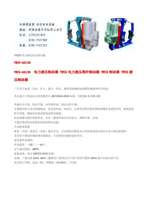
YWZ5电力液压块式制动器YWZ5-400/80YWZ5-400/80 电力液压制动器 YWZ5电力液压推杆制动器 YWZ5制动器 YWZ5液压制动器广泛用于起重、冶金、矿山、港口、码头、建筑等机械驱动装置的减速和停车制动。
其安装尺寸和制动力矩参数符合JB/T6046-2006标准。
匹配Ed系列推动器性能安全可靠、制动平稳、动作频率高、制动力矩可调。
主要摆动铰点设自润滑轴承,传动效率高、寿命长,在使用过程中始终保持两侧瓦块退距均等,避免因退距不均使一侧制动衬垫浮帖制动轮的现象。
制动弹簧布置在弹簧管内,并在一侧设有制动力矩标尺,调整方便,直观。
可通过增设附加装置实现某些附加功能:手动释放装置释放(开闸)或闭合(闭闸)限位开关,可实现制动器是否正常释放或闭合的信号显示或连锁保护。
采用带下降延时阀的推动器推动,可实现制动器的延时闭合。
使用条件和规程:环境温度: -25℃~+45℃。
空气相对湿度:≤90%海拔高度:符合GB755-2000标准。
电源:三相交流50Hz·380V. (根据用户要求也生产用于要求可提供60Hz或不同电压的产品。
适应的工作制:连续(S1)和断续(S3-60%)工作制。
一、概述YWZ 、YWZ2、YWZ3、YWZ4、YWZ5等系列液压块式制动器主要用于起重、运输、冶金、矿山、港口、建筑机械驱动装置的机械制动,具有制动平稳,安全可靠、维修方便、耗电少、寿命长、无噪音等优点。
①WYZ 系列操作次数每小时可达720次。
符合JB/ZQ4388-86标准; ②WYZ2系列操作每小时可达1200次,符合JB/ZQ4388-86标准; ③YWZ3系列操作每小时可达720次,符合GB6333-86标准; ④YWZ4系列操作每小时可达1200次,符合JB/ZQ4388-86标准; ⑤YW Z5系列操作每小时可达1200次,符合GB6333-86标准;二、使用条件1、环境温度-20℃~+50%(低于推动器改为YH-10航空液压油)2、空气相对湿度不大于90%3、一般用于三相交流电源,50HZ,380V;4、海高度符合GB755-87标准;5、在无爆炸危险,且介质中无足以腐蚀金属和破坏绝缘的气体及放电尘埃中;6、YZW、YZW3使用YTI系列推动器,一般适用于垂直工作,倾斜度不超过±去15°三、产品型号及意义四、外形尺寸图五、YWZ5技术数据、外形尺寸表(毫米)BED-80/6隔爆型电力液压推动器BED-80/12隔爆型电力液压推动器品牌:虹发产地:河南价格:1000人民币/台规格:BED-80/6,BED-80/12简要说明:BED系列电力液压推动器主要用作YWZ4,YWZ5,YWZ8,YWZ9,YWZP系列电力液压块式制动器的操作元件,广泛适用于起重运输,冶金,矿山,港口,建筑等行业。
Cubic Electrical Hydraulic Brake YWZ SeriesUsers’Manual(For adjustment and maintenance)brake Co. Ltd. of CityAddress:Tel:Fax:Post Code:Website:E-mail:1. Essentials:Cubic Electrical Hydraulic Brake Series YWZ are mainly used in machines of such uses as craning ,transportation ,metallurgy, mining,porting, constructionand so on. They all accord with the JB/ZQ4388-97 standard.2. Working condifions:2.1 Temperature:-25℃-- +45℃(to see more information in the technical manual of YT1 promoter)2.2 No fire-catching,explosive or corrosive gas in the surrounding erwiroment.Relative air dampness not exceeding 90%.2.3 Power voltage to see the dataplate on promoter.2.4 The working altitude should conform to the standard of GB755-2000.3.Structure and fundamental theories:The Brake consist of a brake frame and a matching YT1 electrical hydraulic promoter when power is on ,the promoter works.Its stem rises quickly and loose the brake by a lever arm .When power off, the promoter’s stem falls quickly because of the push of the return spring and closes the brake by the lever arm .Note: structure may be differentaccording to different type and size(pi cture 1) picture of the structure1.screw bolt screw nut2.frame for installing brake tile3.brake tile4.brake arm5. screw bolt6. screw nut7. screw nut8. screw nut9.pull rod 10. screw nut 11.promoter 12.base4.type and data ( I )5.installation and adjustment5.1 check before installation :● check on the brake to see whether damage or less of parts happened● check and clean oil stains or other dirt on the surface of brakewheel if any5.2 installation of the brake :Please refer to picture I and follon the instructions here :●vertical installation : loose screw nuts number 6.7.8.10 tam thescrew stem 9 take off the brake arm ,and put the brake coat on the brake wheel;●horizontal installation : when brake wheel has been fixed on othermachines , loose screw nuts 6.7.8 and 10 then turn screw stem number9 and add on screw stems 5 and 9 ,put the brake arm on the brakewheel from a side .●After brake has been fixed on the base ,loosely drive the screwbolt on ,turn pull-rod 9.The screw nut in the frame for installing brake tile 2 should be at a proper position to get brake tiles and brake wheel tightly together . If there is still gap between them , continue turning pull rod 9 . Only when the best distance is reached can we stop turning the pull rod 9 and screw the nut tight .●Oil the promoter referring to it’s installations :5.3 Adjustment of the brake :● Adjustment of the promoter when working :First release foyce of the spring to the rising height (H1) of the promoter’s push rod conform to the statistics in table (一). With the wear and tear of the brake liner , working distance gets bigger and bigger , and H1 gets smaller and smaller when the numerial value of H1 gets to the smallest according to table II , ve-adjustment is needed according to the method above , otherwise the brake will become useless .●The adjustment of lever arm :Loosen nut 6, hold the sauare end of the screw-stem 5, drive nut 7, making the spring length conforms to the reference data on the data plate . When all is done , make screw nuts 6 and 7 tight .●The adjustment of returning the distance of the brake scotch : when thebrake tile is opened , adjust bolt 1 , make both sides return the distance and keep unanimity , If this serial brake is equipped with the equal retreat device , by which both sides retreat automatically equal when the brake is turned on , necdn’t adjust .●The nut 2 of the regular brake scotch (see the fig) should be fixed inconformity with elasticity to make the brake scotch can be up to the location with making driving wheel .6. Inspection and trying out before the brake is operated :6.1 Checking before running : The brake should be checked in an all-roundway before running , check whether every adjustment is correct , whether the locknut of every part is locked , impeller wiring is correct .6.2 Test run : Through check , all after being normal , brake should be testedfor several times at host engine , apply the brake liner carry on certain brake- in , in order to make them run well .7. How to use and maintain it :7.1 Check the brake regularly .7.2 Keep in mind the following points when checking .●To see whether any wear and tear has happened to the joints .●Check all parts work normally and all nuts are tight .●Check the rising height (H1) is normal , referring to instruction 5-3 and table I .●Check the hydraulic oil is enough , the oil does n’t leak or seep out and the insulating material wire in good condition .●When bottle and mandrel are worn and torn to 5% or their ellipse exceeds0.5mm , they should be replaced with new ones .●Check the brake tile and wheel are tight together , friction surface is all good and no oil stain and dirt spot . When the thickness of the brake liner gets to minimum , it should be replaced with a new one .。
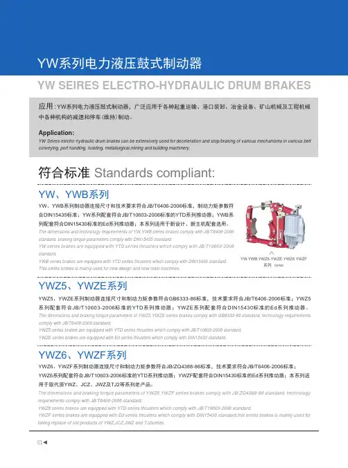
符合标准 Standards compliant:应用:YW 系列电力液压鼓式制动器,广泛应用于各种起重运输、港口装卸、冶金设备、矿山机械及工程机械中各种机构的减速和停车(维持)制动。
Application:YW Seires electro-hydraulic drum brakes can be extensively used for deceleration and stop/braking of various mechanisms in various belt conveying, port handling, hoisting, metallurgical,mining and building machinery.YW 、YWB 系列制动器连接尺寸和技术要求符合JB/T6406-2006标准,制动力矩参数符合DIN15435标准;YW 系列配套符合JB/T10603-2006标准的YTD 系列推动器;YWB 系列配套符合DIN15430标准的Ed 系列推动器;本系列适用于新设计、新主机配套选用。
The dimensions and technology requirements of YW,YWB series brakes comply with JB/T6406-2006 standard, braking torque parameters comply with DIN15435 standard;YW series brakes are equipped with YTD series thrusters which comply with JB/T10603-2006 standard.YWB series brakes are equipped with YTD series thrusters which comply with DIN15430 standard.This series brakes is mainly used for new design and new main machines.YW 、YWB 系列YWZ5、YWZE 系列YWZ6、Y WZF 系列YWZ5、YWZE 系列制动器连接尺寸和制动力矩参数符合GB6333-86标准,技术要求符合JB/T6406-2006标准;YWZ5系列配套符合JB/T10603-2006标准的YTD 系列推动器;YWZE 系列配套符合DIN15430标准的Ed 系列推动器。
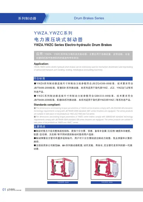
Application:YWZA,YWZC series electro-hydraulic drum brakes can be extensively used for mechanism deceleration and stop/braking of various belt transport, port handling, hoisting, metallurgical and building machinery.■YWZA 系列制动器连接尺寸和制动力矩参数符合JB/ZQ4388-86标准,技术要求符合JB/T6406-2006标准;配套EB1系列推动器。
本系列适用于取代原YWZ 、JCZ 、YWZ 及TJ2等系列老产品。
■YWZC 系列制动器连接尺寸和制动力矩参数符合GB6333-86标准,技术要求符合JB/T6406-2006标准;配套EB 系列推动器。
本系列适用于取代原YWZ3和YWZ □等系列老产品。
Standards compliant:■The dimensions and braking torque parameters of YWZA series brakes comply with JB/ZQ4388-86 standard, technology requirements comply with JB/T6406-2006 standard; EB1 series thrusters are equipped. The series products are suitable to take place of old products as YWZ ,JCZ ,YWZ and TJ2 series.■The dimensions and braking torque parameters of YWZC series brakes comply with GB6333-86 standard, technology requirements comply with JB/T6406-2006 standard; EB series thrusters are equipped. The series products are suitable to take place of old products as YWZ3 and YWZ □ series.YWZA.YWZC 系列电力液压块式制动器YWZA.YWZC Series Electro-hydraulic Drum BrakesYWZA 系列 SeriesYWZC 系列Series ■制动衬垫为卡装式整体成型结构,更换十分方便、快捷,备有半金属(无石棉)硬质和半硬质,软质(含石棉、无石棉)等不同材质的制动衬垫供用户选择。

液压式制动器工作原理
液压式制动器是一种常见的机械制动装置,广泛应用于汽车、飞机、铁路车辆以及重型机械设备等领域。
其工作原理是通过液体的压力来实现制动。
液压式制动器由制动器、制动液压缸以及管路组成。
当踩下制动踏板时,制动器对车轮施加制动力,这个力是由液体压力转换而来的。
液体通过管路流向制动液压缸,当液压缸内的活塞被液压力推动时,制动器就会对车轮施加制动力,从而达到制动的目的。
制动器内部的摩擦材料与车轮接触,产生摩擦力,使车轮停止运动。
当踏板松开时,液压缸内的压力释放,制动器离开车轮,车轮恢复运动。
液压式制动器的工作原理相对简单,但其稳定性和制动性能却非常优秀,是一种可靠的制动装置。
- 1 -。
液压制动器工作原理
液压制动器是一种常见的制动装置,广泛应用于各种车辆和机械设备中。
它通过利用液体的压力来传递力量,从而实现制动的目的。
液压制动器的工作原理主要包括液压传动、制动力的产生和传递、以及制动力的调节等方面。
首先,液压制动器的工作原理涉及液压传动。
液压传动是指利用液体传递能量和动力的一种传动方式。
在液压制动器中,液压传动通过液体在密闭的管路中传递压力,从而实现制动器的工作。
当制动踏板被踩下时,液压系统中的液体被压缩,产生高压,然后通过管路传递到制动器的执行部件,施加力量来实现制动。
其次,液压制动器的工作原理还涉及制动力的产生和传递。
在液压制动器中,制动力是通过液压传动产生的,当制动踏板被踩下时,制动器内的液体被压缩,产生高压,然后通过管路传递到制动器的执行部件,施加力量来实现制动。
这种制动力的传递方式,可以实现在不同位置施加相同的制动力,从而保证了制动的均匀性和稳定性。
最后,液压制动器的工作原理还包括制动力的调节。
在液压制动器中,制动力的大小可以通过调节液压系统中的压力来实现。
通过调节液压系统中的压力,可以实现制动力的大小和施加时间的调节,从而满足不同工况下的制动需求。
总的来说,液压制动器的工作原理是基于液压传动的,通过液体的传递和压力的调节,实现制动力的产生和传递,从而实现制动器的工作。
液压制动器以其结构简单、制动效果稳定等特点,在车辆和机械设备中得到了广泛的应用。
液压制动器原理液压制动器是一种常见的制动装置,它利用液压传动原理实现制动功能。
液压制动器主要由制动缸、制动片、液压管路和液压泵等组成。
在汽车、机械设备和工程机械中广泛应用,下面我们来详细了解一下液压制动器的工作原理。
首先,液压制动器的工作原理基于液压传动。
当制动踏板踩下时,踏板上的主缸活塞受到压力,使制动油液通过液压管路传输到各个制动缸中。
制动缸中的活塞受到液压力的作用,向外推动制动片,使其与制动盘接触,从而实现制动作用。
其次,液压制动器通过液压传动实现力的放大。
当制动油液从主缸传输到制动缸时,由于液体不可压缩的特性,液压力会在制动缸中得到放大。
这种力的放大效应使得制动片能够产生足够的制动力,从而实现快速而有效的制动效果。
另外,液压制动器还具有自动调节制动力的功能。
在制动器工作时,由于摩擦片与制动盘的磨损,制动力会逐渐减小。
但是,液压制动器通过液压传动原理,能够自动调节制动力的大小,保持制动效果的稳定性。
此外,液压制动器还具有防抱死功能。
在车辆紧急制动时,往往会出现车轮抱死的情况,导致车辆失控。
而液压制动器通过智能控制系统,能够实现对车轮制动力的精准控制,避免车轮抱死,提高行驶安全性。
最后,液压制动器还具有高温耐受性和耐磨损性。
在高速行驶或紧急制动时,制动器会产生大量的热量,但是液压制动器通过液压传动原理,能够将热量迅速散发,保持制动器的稳定性。
同时,制动片和制动盘之间的压力通过液压传动实现,减少了摩擦片的磨损,延长了制动器的使用寿命。
综上所述,液压制动器通过液压传动原理实现制动功能,并具有力的放大、自动调节、防抱死、高温耐受和耐磨损等特点,是一种高效、稳定、安全的制动装置。
在实际应用中,需要根据具体车辆和设备的要求,选择合适的液压制动器,并定期进行维护保养,以确保其正常工作和安全使用。
液压制动器一、制动系统概述制动器就是所谓的刹车。
是使机械中的运动件停止或减速的机械零件。
俗称刹车、闸。
制动器主要由制架、制动件和操纵装置等组成。
有些制动器还装有制动件间隙的自动调整装置。
为了减小制动力矩和结构寸,制动器通常装在设备的高速轴上,但对安全性要求较高的大型设备(如矿井提升机、电梯等)则应装在靠近设备工作部分的低速轴上。
有些制动器已标准化和系列化,并由专业工厂制造以供选用。
1 块式制动器shoe brake 靠制动块压紧在制动轮上实现制动的制动器。
单个制动块对制动轮轴压力大而不匀,故通常多用一对制动块,使制动轮轴上所受制动块的压力抵消。
块式制动器有外抱式和内张式两种。
①外抱块式制动器:它按操纵装置行程的长短又分为短行程块式制动器和长行程块式制动器.短行程块式制动器的磁铁直接装在制动臂上。
工作时,动铁芯绕销轴转动实现松闸;磁铁断电时靠主弹簧紧闸。
这种制动器结构紧凑,紧闸和松闸动作快,但冲击力大。
长行程块式制动器可以通过制动杠杆系统产生大的松闸力,但制动动作平稳,适于各种大小型减速设备上。
②内张块式制动器:制动块位于制动轮的内部,通过踏板、拉杆和凸块使制动块张开,压紧制动轮内面而紧闸,松开踏板则弹簧拉回制动块而松闸。
这种制动器也可用液压或气压等操纵。
内张式块式制动器结构紧凑,防尘性好,可用于安装空间受限制的场合,广泛用于各种车辆。
块式制动器制动瓦块该标准适用于外抱双块式制动器。
按制动瓦块(简称制动瓦)与制动衬垫的联接方式,及制动瓦铰轴孔的端部有无沉孔分为以下5种:B1型:制动瓦上铆钉孔,用粘接方式联接制动衬垫,制动瓦铰轴孔的端部无沉孔;B1C型:制动瓦上无铆孔式,用粘接方式联接制衬垫,制动瓦铰轴孔的端部有沉孔;B2型:制动瓦上有铆钉孔,用方式粘接联接制动衬垫,制动瓦铰轴也的端部的端部无沉孔;B2C型:制动瓦上有铆钉孔,用铆接方式联接制动衬垫,制动瓦铰轴也的端部有沉孔. ZK型:制动瓦装卡型 2 盘形制动器盘形制动器是应用于矿井提升机刹车系统的液压执行机构,准确的名称应为:常闭式后置油缸盘形制动器,目前采用较多的是后置式油缸,在提升机启动时,液压站输出压力油打开制动器,提升机开始工作,工作制动时,液压站根据工况升高或降低压力,制动器就会提供与之相反的制动力,在事故状态下,液压站压力回到0压,制动器以最大制动力在最短时间内让提升机停车. 3 失电制动器一> 用途DHD系列制动器为电磁脱离(释放)断电时弹簧施压的摩擦片式制动器(以下简称制动器)。
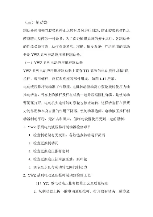
(三)制动器制动器使用来当胶带机停止运转时及时进行制动,防止胶带机惯性运转或防止反转的一种设备。
为了保证输煤系统的安全运行,各制动器的性能必须可靠,动作必须灵活,准确。
输没系统中广泛使用的制动器是YWZ系列电动液压推杆制动器。
(一)Y WZ系列电动液压推杆制动器YWZ系列电动液压推杆制动器主要有TT1系列的电动推杆,制动臂,拉杆,调节螺杆,闸瓦和底座等部件组成。
如图1-17所示。
电动液压推杆制动器工作原理:电机转动驱动离心泵论旋转使压力油推动活塞,活塞上的推杆及杆杠机构一起升压缩圆柱弹簧,是使制动臂闸瓦打开,电动机失电停转时泵轮也停止旋转,这样活塞杆在弹簧力的作用和本身自重的作用下降落,使制动器抱闸。
电动液压推杆制动器制动平稳,无冲击和噪声,但制动较慢使用受到一定的限制。
1.YWZ系列电动液压推杆制动器检修项目1.检查制动架有无变形,各铰链点转动是否灵活2.检查更换制动瓦3.检查更换液压推杆密封4.检查更换液压缸内液压油,泵叶轮5.调节至东瓦与制动轮之间的制动力2.YWZ系列电动液压推杆制动器检修工艺(1)Y T1型电动液压推杆检修工艺及质量标准1.从制动器上拆下的电动液压推杆,打开放有堵头,放净液压油2.按顺序拆下横梁,取下电机,拆去缸盖的连接螺栓,取出叶轮与活塞3.解体清洗后,检查各轴承应转动灵活,叶轮无轴向和径向晃动4.叶轮若破损或腐蚀应更换5.全部零件清洗并核对后进行安装,安装的顺序是:叶轮,活塞与上盖组装为一体,再将叶轮,活塞装入缸体,调整好上盖与箱体,在对成紧固螺栓,最后装复电机,横梁等6.电动液压推杆装复后,叶轮应转动灵活7.推杆与活塞上下运动无卡涩8.结合面密封良好无渗漏,壳体无变形及裂纹(2)制动架的检修工艺及质量标准制动架包括制动轮,闸瓦和支架1.制动轮表面磨损了1.5-2mm时,必须重新车制,并表面淬火2.制动轮车削加工后,壁厚不足原厚的70%时,即应更换3.制动轮装配好后,其端面跳动量不得超过表1-15规定4.闸瓦片磨损不得超过原厚的二分之一,否则应更换,更换制动瓦时,应把石棉切成所需尺寸,最还加热一百摄氏度左右,弯压在闸瓦上,用铝铆钉铆接,闸瓦与瓦片接触面积应大于原面积75%,铆钉沉降头在瓦片上的沉降深度应大于瓦片厚度的二分之一5.制动轮中心与瓦扎中心误差不应超过三毫米,制动器松开时闸瓦与制动器的倾斜度和不平行度不应超过制动轮宽的1‰,如表1-16所示6.制动架各转部分应保证灵活,销轴不能有卡阻,当销轴磨损超过原直径的5%或椭圆度偏差超过0.5毫米时,急需更换7.轴孔直径磨损超过原直径的0.05时,需铰刀绞切并配置新轴8.各转动部分交接点应定期添加润滑油(2)Y WZ系列电动液压推杆制动器的调整制动器调整前,先检查制动轮的中心高度是否相同,两制动臂是否与制动器安装平面相垂直,上述部件在调整符合要求后,才可对制动器进行全面调整,调整过程中,闸瓦及制动轮表面不得有油污1.制动力矩的调整。
YWZ5电力液压块式制动器广泛用于起重、冶金、矿山、港口、码头、建筑等机械驱动装置的减速和停车制动。
其安装尺寸和制动力矩参数符合JB/T6046-2006标准。
匹配Ed系列推动器性能安全可靠、制动平稳、动作频率高、制动力矩可调。
主要摆动铰点设自润滑轴承,传动效率高、寿命长,在使用过程中始终保持两侧瓦块退距均等,避免因退距不均使一侧制动衬垫浮帖制动轮的现象。
制动弹簧布置在弹簧管内,并在一侧设有制动力矩标尺,调整方便,直观。
可通过增设附加装置实现某些附加功能:手动释放装置释放(开闸)或闭合(闭闸)限位开关,可实现制动器是否正常释放或闭合的信号显示或连锁保护。
采用带下降延时阀的推动器推动,可实现制动器的延时闭合。
使用条件和规程:环境温度: -25℃~+45℃。
空气相对湿度:≤90%海拔高度:符合GB755-2000标准。
电源:三相交流50Hz·380V. (根据用户要求也生产用于要求可提供60Hz或不同电压的产品。
适应的工作制:连续(S1)和断续(S3-60%)工作制。
二、使用条件1、环境温度-20℃~+50%(低于推动器改为YH-10航空液压油)2、空气相对湿度不大于90%3、一般用于三相交流电源,50HZ,380V;4、海高度符合GB755-87标准;5、在无爆炸危险,且介质中无足以腐蚀金属和破坏绝缘的气体及放电尘埃中;6、YZW、YZW3使用YTI系列推动器,一般适用于垂直工作,倾斜度不超过±去15°三、产品型号及意义四、外形尺寸图五、YWZ5技术数据、外形尺寸表(毫米) 型号匹配推动器 制动力矩 牛顿·米 退距 A b C d D E F G1 G2 H h1 i K M n 重量YWZ5-160/23 Ed23/5 180 0.8 428 65 160 160 14 150 85 144 191 395 132 55 130 110 8 20 YWZ5-200/23 Ed23/5 112-224 1 448 80 160 100 14 165 90 165 195 487 160 55 145 120 15 27 YWZ5-200/30 Ed30/5 140-315 445 33 YWZ5-250/23 Ed23/5 140-224 1.25 503 100 160 250 18 200 100 200 223 553 190 65 180 145 17 38 YWZ5-250/30 Ed30/5 180-315 500 44。
ZPMCYW.YWB.YWZ5.YWZE SeriesElectro-hydraulic drum brakeContents1. General (1)2. Installation and Adjustment before operation (1)2.1 Installation before the brake installation (1)2.2 Installation of brake (4)2.3Adjustment (6)3. Operation and Maintenance of brake (7)3.1 Operation of brake (7)3.2 Maintenance of brake (8)1.GeneralYW\YWB\YWZ5\YWZE series Electro-hydraulic Drum Brake (hereinafter called brake briefly) is widely used for deceleration and stop/braking of various crane, belt transport, port handling machinery and metallurgical machinery.The construction of drum brake is shown as fig2-1.Principle of operation: When the mechanism is cut off, the thruster- the actuator of the brake is also de-energized (or postponed) and stop driving (thrust is eliminated), the force of brake spring is acted on the braking surface by the both side braking arms, producing a rated pressure to set up a nominated torque. When the mechanism is energized, the thruster start driving and produce a enough force to push up the push-rod, the brake spring is compressed further and the brake arms are opened outside, the brake shoes is free of the brake drum.The brake has such advanced characteristic as shoe aligning, automatic shoe clearance balancing. The brake can equip automatic lining wear compensation device to keep the clearance and torque equal, so it is unnecessary to adjusting during operation.The brake can realized failure signal, lining wear limit indication (interlocking) and other additional function for modern effective handling machinery by equipping additional devices, such as all kinds of limit switch to PLC (programmable control) according to different requirements. In order to ensure the customers use the brake conveniently and safely, hand release lever and safe interlocking switch are also equipped when ordered.In addition the anticorrosive product are supplied, all of the fasten parts and pins are made from stainless steel, the other construction parts are coated anticorrosive paint. The brake fit the condition by the sea and of the steelworks.The brake adopts the company's YTD or Ed series thruster as corollary equipment, advanced technology, reliable quality, long service life and no leakage absolutely. Usually the brake lining is made from a half-metal slim material (non-asbestos). It is a really "natural product"-no noise and no pollution. As the customer requested, the brake lining made from mixture of rubber, asbestos and copper wire is also supplied. 2.Installation and adjustment before operationIn order to ensure the brake operating properly, please install the brake in accordance to the procedure stipulated in the manual correctly. If you need assistance or service of installation, please contact with the company's after-sale department.2.1 Inspection before the brake installation2.1.1 Inspection of brakea. Are the parts and components of the brake complete;The model with addtional functionFig.2-11.lifting spot2.brake spring3.torque adjusting nut4.angle lever5.thruster6.arm7.brake shoe 8.connecting bolt 9.tighten nut 10.balancing lever 11.interlocking pin12.cable entry 13.brake rod pensation device 15.tinhten bolt 16.clearance adjusting nut 17.hand-release lever 18.limit switchStandard modelb. Is the action of brake maneuverable;c. If there is any oil (grease), paint or other contamination stuck on the brake lining that may affect the friction force;d. Check if the type of brake (including electrical voltage , frequency and thrust force of the Electro-hydraulic thruster) meets requirements;If any of all above do not meet the requirement, please resolve the trouble firstly before installation.2.1.2 Inspection of the brake druma. The surface of the brake drum shall not have defects such as corrosion, oil (grease) contamination, unevenness and etc. The brake drum which has cracks or any other defects is strictly prohibited from using;b. When the brake drum rotate around the axis, the diameter run-in shift with the diameter of the brake drum: when the diameter is no more than 250mm,the diameter run-in is limited within 0.1mm,when the diameter is within 250~500mm,the diameter run-in is no more than 0.2mm,when the diameter is within 500~800,the diameter run-in is no more than 0.15;c. Roughness of the both side surfaces of the brake drum shall be 3.2,excessive rough or smooth surfaces may result in difference of braking performance;2.1.3 Construction and inspection of the brake foundation base.a. The brake foundation base shall be firm and lever with accurate installation dimension;b. If the brake foundation base is installed together with the brake, they should be secured (by welding or bolts) after they have been positioned accurately;c. If the installation bores on the brake foundation base have not been drilled, they shall be drilled after the brake has primarily been positioned correctly.The relative tolerance between the surface of the foundation base and the brake drum (refer to fig.2-2) shall not exceed the value listed in table 2-1.Fig.2-2Table 2-1Note: a. Parallelism is of the surface of foundation base and the axis of brake drum.b. The dimension in the parenthesis is of YW\YWB series brake.2.2 Installation of brakeDuring installation, it shall be handled as shown in fig 2-1.It must be noted that handling by brake rod is strictly prohibited.2.2.1 Before installation, choose one side for adjustment and maintenance (usually on the side, which have enough space to adjust and maintain). In order to operate the brake conveniently, please install the balancing lever on the side.2.2.2 Loosen the bolt of the balancing lever and tighten nut to set the balancing lever free (refer to fig.2-3).2.2.3 Set the brake to proper position as following procedures:For the standard product, rotate counterclockwise the brake rod (refer to fig2-4).For the brake with auto-compensation device, loosen the tighten bolt and take off the compensation sleeve, then rotate counterclockwise the clearance adjusting bolt. When necessary, take out the pin.For the brake with hand-release lever, just open the brake by hand-release lever.When the brake is installed between the motor and decelerator, rotate the brake rod to set the brake free (refer to fig2-4).Fig.2-3●●●●●●●bolt connecting boltnut 1nut 2balancing lever interlocking pin self-locking boltboltboltpincompensation sleeveclearanceFIg2-42.2.4After the brake is primarily set, punch the foundation bolt and fix the nut lightly (not tighten), subsequently install the brake again;2.2.5Screw the adjusting nut clockwise to adjust the compensation stroke hb to the value listed in table 2-2 (refer to fig 2-5);Table 2-2Note: the value in the parentheses is of the brake with the compensation device.2.2.6 Remove the cover of terminal box, install the thruster power supply and ground line according to the stipulation (refer to fig 2-6).Fig.2-6After connection, cover the terminal box and tighten lock nut.Note: The protection class is IP55.The cable income through stuffing box.Cable entry M27×5,with conductor normal section area may be 4×1.5mm ,max 4×2.5mm .The customer can choose earthing screw inside and outside terminal box to use according to requirement. The connection of motor coil(Y/△) is finished before delivery. Connection shall strictly comply with the regulation.2.2.7 The brake shall be energize intermittently for 20~30 times to realize self-centering and other adjustment. Check if the installation position is right after the brake is de-energized.2.2.8Refer to fig.2-3 to adjust the nut and the connecting bolt of brake rod, put the clearance balancing lever horizontally. During adjustment, it must be noted that the distance between the balancing lever and the brake drum should keep more over 3mm and the distance between the foundation base and the brake drum is more over 12mm.2.2.9Tighten the foot bolt and the self-locking nut of the brake rod, finish the installation.2.3 AdjustmentThe brake shall be adjusted before first installation (operation) or after replacement of the brake lining.2.3.1 Adjustment of braking torque: the brake torque shall be adjusted to the rated value (max) at factory before shipped. The customer can change the braking torque from 100% to 50% rated value according to the factual requirement .The length of spring is ratio oppositely with the braking torque.Fig.2-5W2U2L3L2L1V1U1W1V1W2U2U1L1L2V2V2W1L3L3L2L1Cable entry 22Turn the braking torque adjusting bolt clockwise with spanner (refer to fig 2-5 and 2-1), the length of brake spring becomes shorter, the braking torque increases, on the contrary the braking torque reduces.It is noted that the braking torque shall not exceed the range listed on nameplate (refer to fig.2-7), otherwise it will affect the brake application.2.3.2 The adjustment of compensation stroke of thruster: the working stroke h is direct ratio to the brake lining clearance. The relation among the working stroke h, the rated stroke H and the compensation stroke hb is shown as the following equation: h=H- h b When the brake are equipped the automatic wear compensation device and the clearance of the brake shoe have been adjusted before delivery. It is usually unnecessary to adjust during operation unless installation or replacement of the brake lining is done. Refer to section2.2.3, section2.2.5 and fig.2-1 to adjust the stroke.2.3.3 Adjustment of the brake shoe clearanceThe brake have interlocking shoe clearance balancing device (patented technology, refer to fig.2-3). During operation you need not adjust them. If the clearance between brake shoe and brake surface are not obviously equal (the lining of one side stick to brake drum when the brake is in released condition), check if the nuts of balancing device are loosen and close the brake to tighten the nuts.It must be noted that the shoe clearance balancing is set horizontally.3. Operation and maintenance of brake3.1 Operation of brake3.1.1the following check shall be carried out before using brake.a. Check if the installation of brake meets requirement;b. The type of Electro-hydraulic thruster, voltage, frequency (listed on nameplate), the wiring and lubrication shall accord with the requirement;c. The adjustment and testing of brake meets requirement;d. Check if the length of brake spring meet requirement ;e. Check if there is oil (grease) contamination on the brake lining and brake disc.3.1.2 After check, the brake performs static running in for 25~30 times, that means the brake is applied when the main motor is not activated.Intermittent periodic duty: Duty-cycle is 40%, one operating cycle take five seconds. If there is strange phenomenon, please resolve the problem refer to the regulation in chapter 2 and test the brake until the brake operates normally.3.1.3 Set the load-factor is 30%~50%, adjust the braking torque to 50% of rated, perform dynamic running in for 10~15 times according to 3.1.2 until the operation is steady.3.1.4 After all right, adjust torque to the rated, then brake can be operated normally. 3.2.Maintenance of brakeBrake should be checked every 1~3 days as following:a. Check whether the brake working stroke (clearance of the shoe) is normal or not;b. Check if the automatic compensation device is worn and the compensation sleeve and tighten nut is loosen;c. Check the length of brake spring;d. Check if the plate of limit switch is installed correctly and firmly;e. Check if there is oil (grease) on the brake drum and brake shoe.f. Check the wear of brake lining. The brake lining shall be replaced if its thickness is worn to <3mm only. After replacement of brake lining, running in shall be carried out;h. During emergency braking there may be some colored spots .If serious cracks occur, replace the brake drum.3.2.2 Inspection during operationDuring operation the following matters shall be inspected timely.a. Any increment of the braking time and braking distance.b. Any over-speed of brake disc appeared during equipment operation;c. The operation of limit switch is exactly correct;d. Check if the temperature of brake drum and brake lining are beyond 350 or brake drum and brake lining is smoking. If this unusual phenomenon appears, you shall stop braking and start checking. After understanding reason of troubles and getting rid of them, you can use the brake again.3.2.3 RepaintingPainting shall be damaged during transportation, storage, installation and operation .It is necessary to repaint timely or else the anticorrosive performance of brake will be reduced. In case of repainting the following locations shall not be contaminated:a. Various linkage;b. Brake drum and brake lining surface;c. Automatic compensation device and Electro-hydraulic thruster piston rod surfaces;d. Surface of the shaft;.3.2.4Lubrication: self-lubricated bearing are used in the brake and it is not necessary to grease during operation.3.2.5Replacement of brake lining:After a period of operation, the brake lining is worn and if it is worn to <3mm in thickness, it shall be replaced. During replacement of brake lining, attention shall be paid to safety due to their heavy weight.a. Completely release the brake according to section 2.2.3 ;b. Screw down the nut of the pressure back on the top of brake lining and take out the adjusting pillow (refer to fig3-1) ;c. Hold the brake lining and pick out it along the brake drum;d. Insert new lining to the installation position correctly;e. Reset the pressure back, baffle and tighten the connecting bolt in turn. The brake lining should stick the brake shoes closely and well. The clearance at any point of the brake surface shall be no more than 0.5mm.In order to ensure the brake lining firm and reliable, the gap between the brake lining and the brake shoes, C should be conformity with the stipulation in fig3-1 and table3-1. The thickness of the brake lining covered by the pressure back and baffle shall be no more than 1/2 of the original thickness and not less than 1/3 of the original thickness (inclusive of the steel back).After replacement, please check the brake lining, running-in and testing (refer to fig 3-1).3.2.6 Maintenance of thrusterThe brake adopts the company's YTD or Ed thruster as corollary equipment. It is basically free of maintenance.The thruster is oiled before delivery. If the thruster need to add or replace hydraulic oil, please refer to the operation instruction of Electro-hydraulic thruster.Fig.3-1Table 3-1Warning:Only use the spares and parts from our company(ZPMC) or approbated by it!Otherwise,performance of the brake cannot be guaranteed!。
YWZ5-200/30 电力液压块式制动器
YWZ5-200/30电力液压制动器 YWZ5电力液压推杆制动器 YWZ5制动器 YWZ5液压制动器
广泛用于起重、冶金、矿山、港口、码头、建筑等机械驱动装置的减速和泊车制动。
其安装尺寸和制动力矩参数符合JB/T6046-2006尺度。
匹配Ed系列推动器
机能安全可靠、制动平稳、动作频率高、制动力矩可调。
主要摆动铰点设自润滑轴承,传动效率高、寿命长,在使用过程中始终保持两侧瓦块退距均等,避免因退距不均使一侧制动衬垫浮帖制动轮的现象。
制转动簧布置在弹簧管内,并在一侧设有制动力矩标尺,调整利便,直观。
可通过增设附加装置实现某些附加功能:
手动开释装置
开释(开闸)或闭合(闭闸)限位开关,可实现制动器是否正常开释或闭合的信号显示或连锁保护。
采用带下降延时阀的推动器推动,可实现制动器的延时闭合。
使用前提和规程:
环境温度: -25℃~+45℃。
空气相对湿度:≤90%
海拔高度:符合GB755-2000尺度。
电源:三相交流50Hz·380V. (根据用户要求也出产用于要求可提供60Hz或不同电压的产品。
适应的工作制:连续(S1)和断续(S3-60%)工作制。
液压制动器工作原理液压制动器是一种常见的制动装置,它通过利用液压原理来实现车辆制动。
液压制动器主要由制动踏板、主缸、助力器、制动盘和制动片等部件组成。
在车辆行驶过程中,当驾驶员踩下制动踏板时,制动力会通过主缸产生液压信号,然后通过助力器将液压信号传递给制动盘和制动片,最终实现车辆的制动。
液压制动器的工作原理主要包括以下几个方面:1. 制动踏板传递力量。
当驾驶员踩下制动踏板时,踏板上的力量会通过连杆传递给主缸。
主缸内部有活塞,当受到外力作用时,活塞会向前移动,从而产生液压信号。
2. 液压信号传递。
主缸内的液体会随着活塞的移动而产生压力,这个压力会通过管路传递给助力器。
助力器起到放大液压信号的作用,使得制动力得到增强,从而提高制动效果。
3. 制动盘和制动片的工作。
助力器传递的液压信号最终会到达制动盘和制动片。
制动盘和制动片之间的摩擦产生制动力,使车辆减速或停止。
液压制动器通过以上工作原理实现了对车辆的制动控制。
在实际使用中,液压制动器还需要配合制动液、制动管路等部件共同完成制动任务。
此外,液压制动器还需要定期保养和维护,以确保其正常工作。
总的来说,液压制动器工作原理简单清晰,通过液压传递力量,最终实现对车辆的制动控制。
对于驾驶员来说,了解液压制动器的工作原理有助于更好地掌握车辆的制动性能,提高行车安全。
同时,在日常维护中,对液压制动器的工作原理有深入的了解,也有助于及时发现并解决潜在的故障问题,保障行车安全。
通过对液压制动器工作原理的深入了解,我们可以更好地理解车辆制动系统的工作原理,从而更好地掌握车辆的制动性能。
同时,对于液压制动器的维护和保养也有了更清晰的认识,有助于确保车辆的行车安全。
因此,了解液压制动器的工作原理对于驾驶员和维修人员来说都是非常重要的。
YWZ5制动器
电力液压块式制动器广泛用于起重、冶金、矿山、港口、码头、建筑机械等机械驱动装置的减速或停车制动。
性能安全可靠,制动平稳,动作频率高。
主要摆动铰点设有自润滑轴承,传动效率高、寿命长,在使用过程中无需润滑。
符合标准
安装尺寸符合GB633-1986标准。
制动器使用条件
制动器环境温度:-20℃~+50℃
空气相对温度不大于90%
周围工作环境不得有易燃、易爆及腐蚀性气体
使用地点的海拔高度符合GB755-2000
户外雨雪侵蚀或有腐蚀性气体和介质应采用防腐型产品。